
A Hybrid Flexible Neutral Grounding Mode for Large Generators


Abstract
:1. Introduction
2. Hybrid Flexible Neutral Grounding Mode for Large Generators
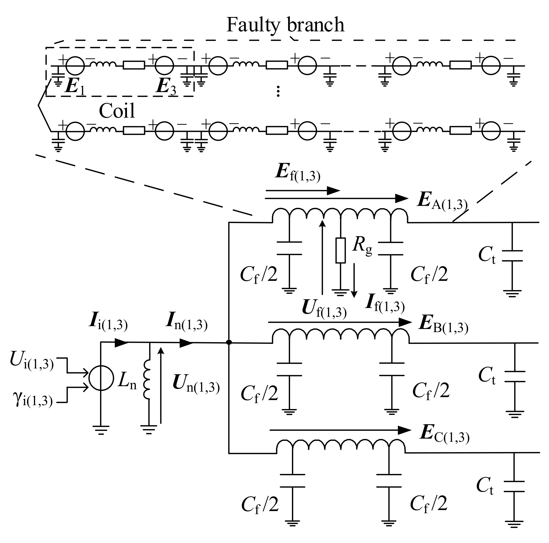
2.1. Arc Suppression Mechanism
2.2. Implementation of the Hybrid Flexible Grounding Mode
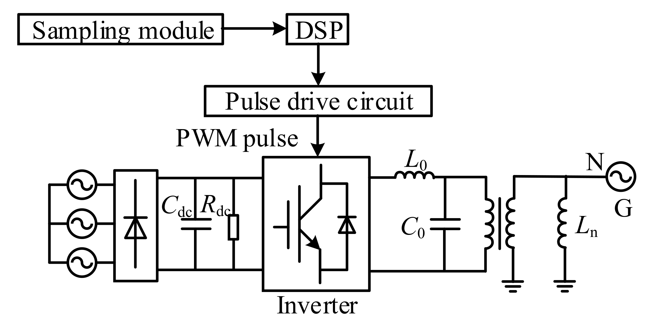
2.2.1. Topology of the Active Arc-Suppression Device
2.2.2. Requirements of the Inverter Capacity
3. Fault-Type Identification Method Based on Third-Harmonic Quantities
4. Simulation Verification
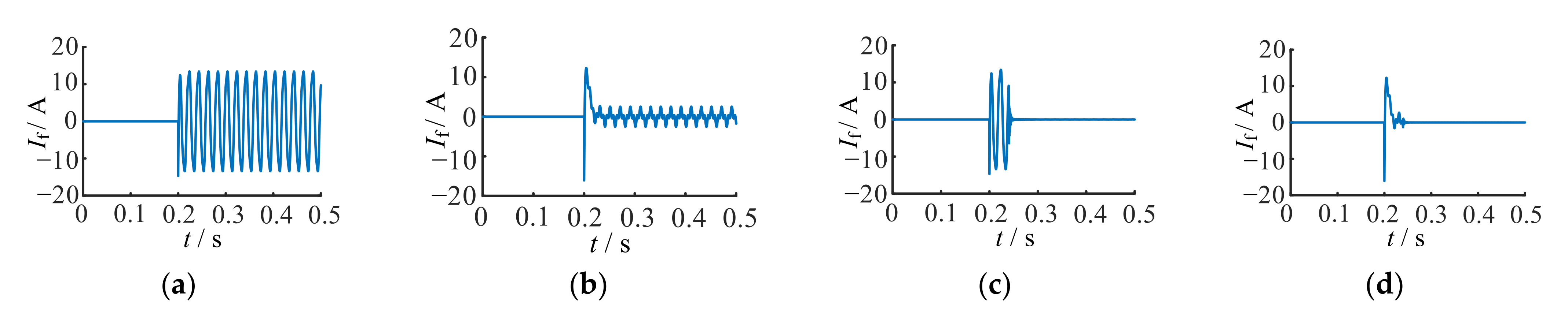
4.1. Verification of the Arc-Suppression Effect
4.2. Simulation Analysis of the Inverter Capacity
4.3. Verification of the Proposed Fault-Type Identification Method
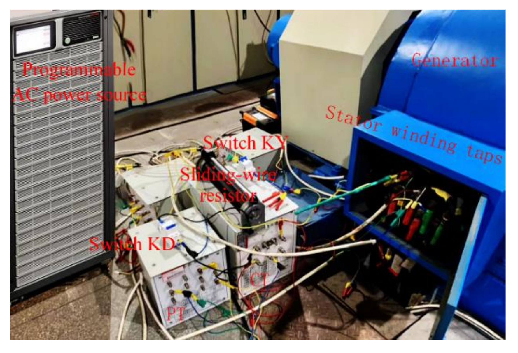
5. Dynamic Test Verification
6. Conclusions
- (1)
- The hybrid flexible grounding method achieved reliable arc suppression. Simulation results verify that it was not affected by the fault position or the grounding transition resistance. Experimental results verify that it was not affected by the system-operating condition and the generator excitation regulation.
- (2)
- Because the arc-suppression coil could compensate for most of the fundamental components, the fundamental current injected by the dual-frequency active arc-suppression device was greatly reduced. The capacity of the inverter only needed about 20 kVA, which greatly reduced the volume and the cost.
- (3)
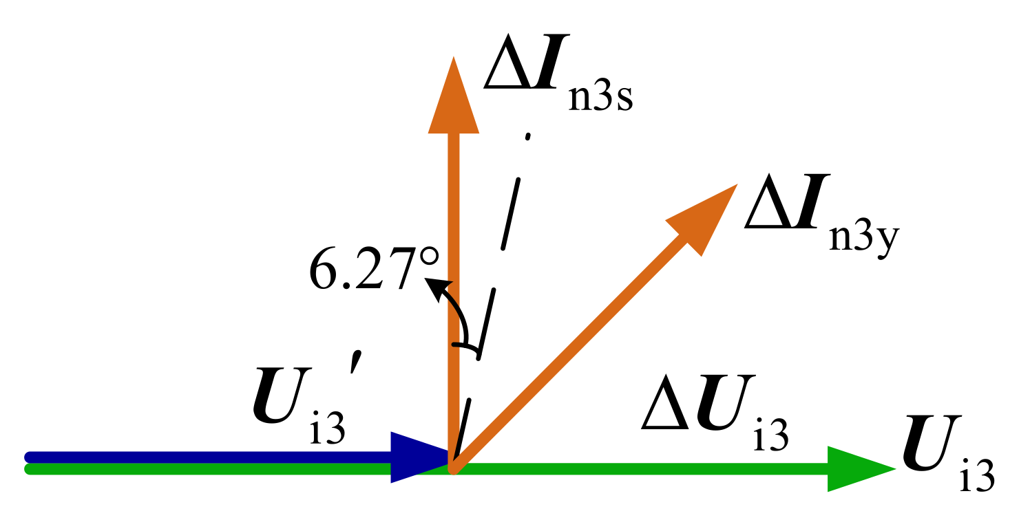
- For instantaneous ground faults, the phase-angle difference between the third-harmonic voltage and current variation at the generator neutral point was close to 90°. For permanent ground faults, the above relation could not be satisfied since the neutral line current contained certain resistive components. Under different fault scenarios, according to Equation (8), the fault type identification could be reliably realized.
Author Contributions
Funding
Institutional Review Board Statement
Informed Consent Statement
Data Availability Statement
Conflicts of Interest
References
- Fulczyk, M.; Bertsch, J. Ground fault currents in unit-connected generators with different elements grounding neutral. IEEE Trans. Energy Convers. 2002, 17, 61–66. [Google Scholar] [CrossRef]
- Wang, Y.K.; Yin, X.G.; Qiao, J.; Tan, L.M.; Xu, W.; Li, W. Generator stator windings ground fault diagnosis for generator–grid directly connected system of floating nuclear power plant. Energy Rep. 2021, 7, 460–469. [Google Scholar] [CrossRef]
- Wu, A.Y. MV Generator Ground Fault Arcing Power Damage Assessment. IEEE Trans. Ind. Appl. 2018, 54, 912–915. [Google Scholar] [CrossRef]
- Tai, N.L.; Stenzel, J. Differential protection based on zero-sequence voltages for generator stator ground fault. IEEE Trans. Power Del. 2007, 22, 116–121. [Google Scholar]
- Yin, X.G.; Malik, O.P.; Hope, G.S.; Chen, D.S. Adaptive ground fault protection schemes for turbogenerator based on third harmonic voltages. IEEE Trans. Power Del. 1990, 5, 595–603. [Google Scholar] [CrossRef]
- Safari-Shad, N.; Franklin, R.; Negahdari, A.; Toliyat, H.A. Adaptive 100% Injection-Based Generator Stator Ground Fault Protection with Real-Time Fault Location Capability. IEEE Trans. Power Del. 2018, 33, 2364–2372. [Google Scholar] [CrossRef]
- Ding, W.L.; Luo, J.; Li, J. Stator Ground Fault Protection of Direct Generator-Bus Connection. Autom. Elect. Power Syst. 2007, 31, 74–78. [Google Scholar]
- Gulachenski, E.M.; Courville, E.W. New England Electric’s 39 years of experience with resonant neutral grounding of unit-connected generators. IEEE Trans. Power Del. 1991, 6, 1016–1024. [Google Scholar] [CrossRef]
- Jia, W.C.; Cao, S. Parameter optimization design of combination-type grounding mode for large-sized hydropower units. Elect. Power Autom. Equip. 2022, 4, 79–85. [Google Scholar]
- Yin, X.G.; Wang, Y.K.; Li, P.; Xu, W.; Wu, D.L.; Qiao, J.; Liu, X.Y. Study on security problems and protection technologies of the floating nuclear power plant grid. Power Syst. Prot. Cont. 2020, 48, 9–17. [Google Scholar]
- Burgess, R.; Ahfock, A. Minimising the risk of cross-country faults in systems using arc suppression coils. IET Gene. Trans. Distr. 2011, 5, 703–711. [Google Scholar] [CrossRef]
- Yu, K.; Liu, Z.L.; Zeng, X.J.; Li, J.Z.; Yang, L. A novel full compensation method for the ground fault current of resonant grounded systems. Electr. Eng. 2021, 103, 1569–1581. [Google Scholar] [CrossRef]
- Wang, Y.K.; Yin, X.G.; Xu, W.; Qiao, J.; Tan, L.M. Active Arc Suppression Algorithm for Generator Stator Winding Ground Fault in the Floating Nuclear Power Plan. IEEE Trans. Power Del. 2022; early access. [Google Scholar]
- Friedemann, D.F.; Motter, D.; Oliveira, R.A. Stator-Ground Fault Location Method Based on Third-Harmonic Measures in High-Impedance Grounded Generators. IEEE Trans. Power Del. 2021, 36, 794–802. [Google Scholar] [CrossRef]
- Rifaat, R.M. Utilizing third harmonic 100% stator ground fault protection, a cogeneration experience. Proc. IEEE Conf. Ind. Appl. 2000, 5, 3254–3259. [Google Scholar]
- Xiong, B.; Zhou, L.; Ding, S. Study on Dynamic Characteristics of Single-Phase Grounding Fault of 1000 MW Hydro Generator under Different Grounding Modes. Machines 2022, 10, 554. [Google Scholar] [CrossRef]
- Powell, L.J. Stator Fault Damage Considerations for Generators on Solidly Grounded Systems. IEEE Trans. Ind. Appl. 2001, 37, 218–222. [Google Scholar] [CrossRef]
- Yao, H.N.; Cao, M.Y. Power System Resonance Grounding Theory; China Electric Power Press: Beijing, China, 2009; pp. 40–45. [Google Scholar]
- Wang, W.; Zeng, X.J.; Yan, L.J.; Xu, X.Y.; Guerrero, J.M. Principle and Control Design of Active Ground-Fault Arc Suppression Device for Full Compensation of Ground Current. IEEE Trans. Ind. Electron. 2017, 64, 4561–4570. [Google Scholar] [CrossRef]
- Fan, B.S.; Yao, G.Z.; Yu, K.; Zeng, X.J.; Wang, W.; Zhuo, C.; Guerrero, J.M. Principle of Flexible Ground-Fault Arc Suppression Device Based on Zero-Sequence Voltage Regulation. IEEE Access 2020, 9, 2382–2389. [Google Scholar] [CrossRef]
- Fan, B.S.; Yao, G.Z.; Wang, W.; Zeng, X.J.; Guerrero, J.M.; Yu, K.; Zhuo, C. Principle and Control Design of a Novel Hybrid Arc Suppression Device in Distribution Networks. IEEE Trans. Ind. Electron. 2022, 69, 41–51. [Google Scholar] [CrossRef]
- Xu, X.Z.; Hu, W.G. Modeling and simulation of arc grounding fault of middle and low voltage distribution network based on ATP-EMTP. J. Comput. Methods Sci. Eng. 2020, 20, 1279–1288. [Google Scholar] [CrossRef]


| Symbols | Description |
|---|---|
| EA | Electric potential of phase A |
| EB | Electric potential of phase B |
| EC | Electric potential of phase C |
| E1 | Fundamental coil potential of the first coil in the faulty branch |
| E3 | Third-harmonic coil potential of the first coil in the faulty branch |
| Cf | Equivalent grounding capacitance of the generator stator windings for per phase |
| Ct | Equivalent grounding capacitance of the directly connected equipment for per phase |
| Rg | Grounding transition resistance |
| Uf | Fault point voltage |
| If | Fault current |
| Un | Generator neutral-point voltage |
| In | The current flowing through the neutral line |
| Ln | Equivalent inductance value of the arc-suppression coil |
| Ui | The amplitude of the output voltage by the active arc-suppression device |
| γi | The phase angle of the output voltage by the active arc-suppression device |
| Ii | The injected current from the active arc-suppression device |
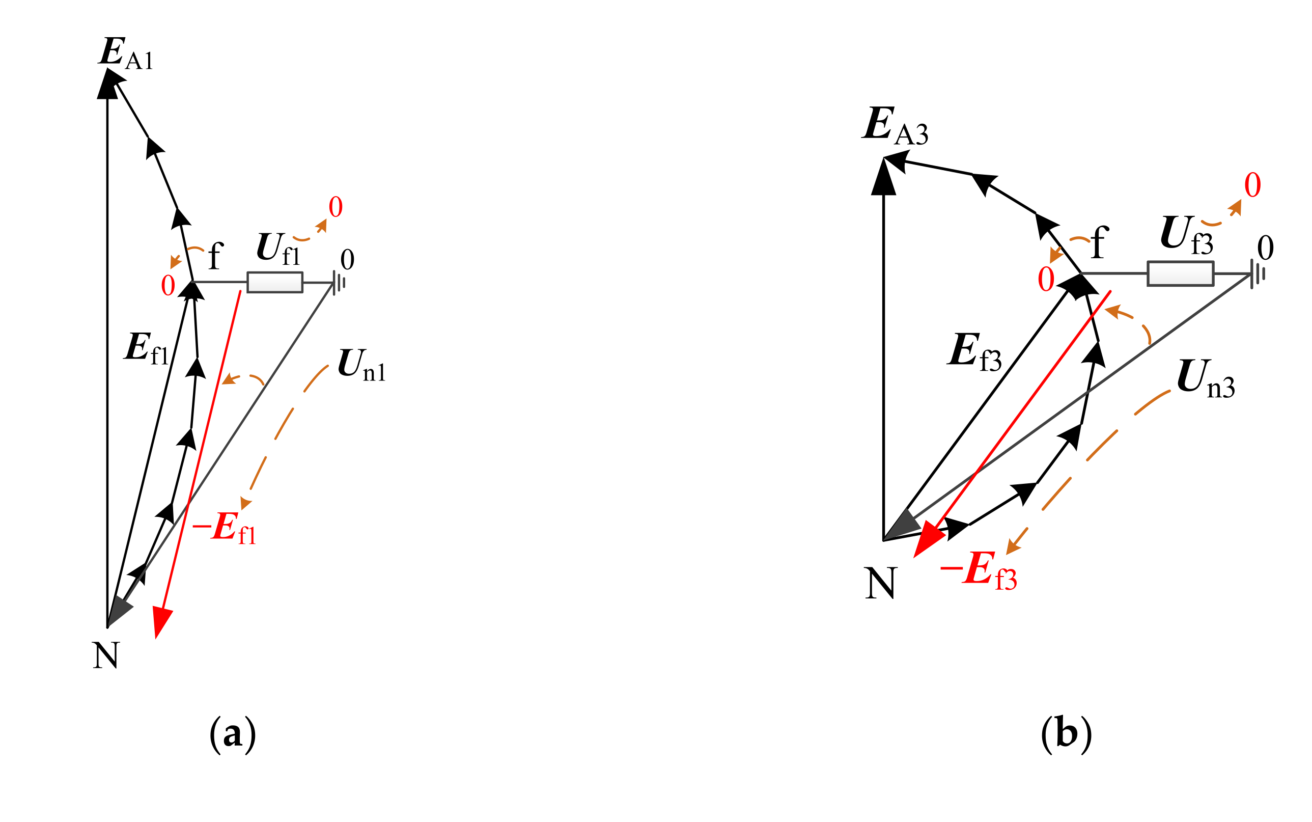
| Ef | Fault potential (the induced potential between the generator neutral point and the fault point) |
| f | The fault point |
| L0 | Inductance value of the filter in the active arc-suppression device |
| C0 | Capacitance value of the filter in the active arc-suppression device |
| Cdc | Capacitance value of the DC side in the active arc-suppression device |
| Rdc | Resistance value of the DC side in the active arc-suppression device |
| ∆Un1 | Fundamental neutral-point voltage variation after putting in the active arc-suppression device |
| ∆Un3 | Third-harmonic neutral-point voltage variation after putting in the active arc-suppression device |
| C∑ | Sum of the three-phase grounding capacitances of the system |
| Angular frequency of the power system | |
| ∆In3 | Third-harmonic current variation of the neutral line |
| ∆In3s | Third-harmonic current variation of the neutral line for instantaneous faults |
| ∆In3y | Third-harmonic current variation of the neutral line for permanent faults |
| ∆Ui3 | Injected third-harmonic voltage variation |
| S | Injected capacity of the dual-frequency active arc-suppression device |
| α | Fault position (percentage per ratio of the winding turns between the neutral point and the fault point of the stator-winding turns and the complete branch-winding turns) |
| θ | Phasor-angle difference between ∆In3 and ∆Ui3 |
| α | |Ef1|/V | φf1/° | |Ef3|/V | φf3/° |
|---|---|---|---|---|
| 0.125 | 1812.5 | −52.5 | 449.9 | 22.5 |
| 0.25 | 3617.2 | −48.75 | 882.6 | 33.75 |
| 0.375 | 5406.5 | −45 | 1281.4 | 45 |
| 0.5 | 7172.6 | −41.25 | 1630.9 | 56.25 |
| 0.625 | 8908.0 | −37.5 | 1917.7 | 67.5 |
| 0.75 | 10,605.4 | −33.75 | 2130.9 | 78.75 |
| 0.875 | 12,257.5 | −30 | 2262.1 | 90 |
| 1 | 13,856.3 | −26.25 | 2306.4 | 101.25 |
| Fault Scenario | Uf /V | If /V | |
|---|---|---|---|
| α | Rg/Ω | ||
| 0 | 50 | 7.22 | 0.14 |
| 500 | 7.22 | 0.01 | |
| Cassie | 7.84 | 0 | |
| 0.125 | 50 | 4.77 | 0.06 |
| 500 | 4.77 | 0.01 | |
| Cassie | 4.77 | 0 | |
| 0.25 | 50 | 5.15 | 0.07 |
| 500 | 5.16 | 0.01 | |
| Cassie | 5.15 | 0 | |
| 0.375 | 50 | 5.25 | 0.07 |
| 500 | 5.26 | 0.01 | |
| Cassie | 5.25 | 0 | |
| 0.5 | 50 | 5.05 | 0.07 |
| 500 | 5.06 | 0.01 | |
| Cassie | 5.06 | 0 | |
| 0.625 | 50 | 4.60 | 0.07 |
| 500 | 4.61 | 0.01 | |
| Cassie | 4.61 | 0 | |
| 0.75 | 50 | 4.12 | 0.07 |
| 500 | 4.12 | 0.01 | |
| Cassie | 4.13 | 0 | |
| 0.875 | 50 | 3.88 | 0.07 |
| 500 | 3.89 | 0.01 | |
| Cassie | 3.89 | 0 | |
| 1 | 50 | 3.43 | 0.07 |
| 500 | 3.43 | 0.01 | |
| Cassie | 3.44 | 0 | |
| Fault Scenario | Injected Quantities of the Inverter | ||||||||
|---|---|---|---|---|---|---|---|---|---|
| α | Rg/Ω | Ui1/V | Ui3/V | Dual-Frequency Active Arc-Suppression Mode | Hybrid Flexible Grounding Mode | ||||
| Ii1/A | Ii3/A | S/kVA | Ii1/A | Ii3/A | S/kVA | ||||
| 0 | 50 | 0 | 10 | 0 | 4.01 | 0.04 | 0 | 4.01 | 0.04 |
| 500 | 0 | 4.02 | 0.04 | 0 | 4.02 | 0.04 | |||
| Cassie | 0 | 4.01 | 0.04 | 0 | 4.00 | 0.04 | |||
| 0.125 | 50 | 1812.5∠127.5 | 449.9∠−157.5 | 1.36 | 3.75 | 4.16 | 0.13 | 3.77 | 1.94 |
| 500 | 1.37 | 3.75 | 4.17 | 0.14 | 3.76 | 1.94 | |||
| Cassie | 1.37 | 3.75 | 4.16 | 0.14 | 3.77 | 1.94 | |||
| 0.25 | 50 | 3617.2∠131.25 | 882.6∠−146.25 | 2.73 | 3.34 | 12.83 | 0.27 | 3.37 | 3.96 |
| 500 | 2.73 | 3.35 | 12.85 | 0.28 | 3.36 | 3.97 | |||
| Cassie | 2.72 | 3.34 | 12.84 | 0.28 | 3.37 | 3.96 | |||
| 0.375 | 50 | 5406.5∠135 | 1281.4∠−135 | 4.09 | 2.83 | 25.73 | 0.40 | 2.84 | 5.84 |
| 500 | 4.08 | 2.82 | 25.72 | 0.41 | 2.84 | 5.84 | |||
| Cassie | 4.09 | 2.84 | 25.73 | 0.40 | 2.84 | 5.85 | |||
| 0.5 | 50 | 7172.6∠138.75 | 1630.9∠−123.75 | 5.42 | 2.24 | 42.56 | 0.53 | 2.22 | 7.48 |
| 500 | 5.43 | 2.24 | 42.56 | 0.53 | 2.23 | 7.49 | |||
| Cassie | 5.41 | 2.25 | 42.58 | 0.53 | 2.22 | 7.48 | |||
| 0.625 | 50 | 8908.0∠142.5 | 1917.7∠−112.5 | 6.73 | 1.63 | 63.14 | 0.67 | 1.52 | 8.87 |
| 500 | 6.73 | 1.62 | 63.15 | 0.68 | 1.52 | 8.87 | |||
| Cassie | 6.72 | 1.63 | 63.14 | 0.67 | 1.54 | 8.88 | |||
| 0.75 | 50 | 10605.4∠146.25 | 2130.9∠−101.25 | 8.01 | 1.16 | 87.53 | 0.79 | 0.81 | 10.18 |
| 500 | 8.00 | 1.16 | 87.52 | 0.79 | 0.80 | 10.18 | |||
| Cassie | 8.01 | 1.17 | 87.54 | 0.79 | 0.82 | 10.19 | |||
| 0.875 | 50 | 12257.5∠150 | 2262.1∠−90 | 9.26 | 1.11 | 116.13 | 0.92 | 0.48 | 12.38 |
| 500 | 9.25 | 1.12 | 116.12 | 0.93 | 0.49 | 12.40 | |||
| Cassie | 9.26 | 1.10 | 116.13 | 0.92 | 0.50 | 12.39 | |||
| 1 | 50 | 13856.3∠153.75 | 2306.4∠−78.75 | 10.48 | 1.53 | 148.73 | 1.03 | 1.05 | 16.81 |
| 500 | 10.48 | 1.53 | 148.73 | 1.04 | 1.08 | 16.83 | |||
| Cassie | 10.50 | 1.52 | 148.72 | 1.04 | 1.07 | 16.83 | |||
| Fault Scenario | θ/° | ||
|---|---|---|---|
| α | Rg/Ω | Transient | Permanent |
| 0 | 50 | 85.42 | 2.16 |
| 500 | 85.69 | 10.75 | |
| Cassie | 85.52 | 6.79 | |
| 0.125 | 50 | 85.48 | 13.48 |
| 500 | 85.74 | 21.56 | |
| Cassie | 86.90 | 17.27 | |
| 0.25 | 50 | 87.13 | 19.53 |
| 500 | 87.92 | 21.36 | |
| Cassie | 87.54 | 20.67 | |
| 0.375 | 50 | 87.98 | 22.05 |
| 500 | 88.82 | 23.16 | |
| Cassie | 88.06 | 22.67 | |
| 0.5 | 50 | 89.08 | 25.56 |
| 500 | 89.24 | 28.35 | |
| Cassie | 89.18 | 27.33 | |
| 0.625 | 50 | 89.22 | 30.18 |
| 500 | 89.54 | 33.55 | |
| Cassie | 89.37 | 32.48 | |
| 0.75 | 50 | 89.78 | 38.71 |
| 500 | 89.84 | 40.42 | |
| Cassie | 89.79 | 39.41 | |
| 0.875 | 50 | 89.90 | 43.56 |
| 500 | 89.94 | 45.14 | |
| Cassie | 89.91 | 44.12 | |
| 1 | 50 | 89.91 | 51.45 |
| 500 | 89.92 | 54.15 | |
| Cassie | 89.90 | 52.81 | |
| Operation Mode | θ/° | |
|---|---|---|
| Transient | Transient | |
| No-load condition | 88.22 | 42.16 |
| 50% load condition | 87.96 | 40.79 |
| 100% load condition | 87.52 | 40.75 |
Publisher’s Note: MDPI stays neutral with regard to jurisdictional claims in published maps and institutional affiliations. |
© 2022 by the authors. Licensee MDPI, Basel, Switzerland. This article is an open access article distributed under the terms and conditions of the Creative Commons Attribution (CC BY) license (https://creativecommons.org/licenses/by/4.0/).
Share and Cite
Wang, Y.; Yin, X.; Yin, X.; Qiao, J.; Tan, L. A Hybrid Flexible Neutral Grounding Mode for Large Generators. Machines 2022, 10, 684. https://doi.org/10.3390/machines10080684
Wang Y, Yin X, Yin X, Qiao J, Tan L. A Hybrid Flexible Neutral Grounding Mode for Large Generators. Machines. 2022; 10(8):684. https://doi.org/10.3390/machines10080684
Chicago/Turabian StyleWang, Yikai, Xin Yin, Xianggen Yin, Jian Qiao, and Liming Tan. 2022. "A Hybrid Flexible Neutral Grounding Mode for Large Generators" Machines 10, no. 8: 684. https://doi.org/10.3390/machines10080684
APA StyleWang, Y., Yin, X., Yin, X., Qiao, J., & Tan, L. (2022). A Hybrid Flexible Neutral Grounding Mode for Large Generators. Machines, 10(8), 684. https://doi.org/10.3390/machines10080684