Article

Mechanical Analysis of Deformation Law in the Flange Area of Box-Shaped Parts during Deep Drawing

1
Key Laboratory of Advanced Forging & Stamping Technology and Science (Yanshan University), Ministry of Education of China, Qinhuangdao 066004, China
2
School of Mechanical Engineering, Yanshan University, Qinhuangdao 066004, China
*
Author to whom correspondence should be addressed.
Machines 2022, 10(8), 667; https://doi.org/10.3390/machines10080667
Submission received: 14 July 2022 / Revised: 2 August 2022 / Accepted: 5 August 2022 / Published: 9 August 2022
(This article belongs to the Section Material Processing Technology)

Abstract

:
The investigation of deformation law is the theoretical basis for analyzing instability wrinkling and forming performance during the sheet-metal-forming process. In order to explore the deformation law in the flange area of box-shaped parts and conduct qualitative and quantitative analysis on stress and strain, it is assumed that the deformation law of the mass point on the zero line of shear stress in the corner area is equal to that of the axisymmetric parts. Based on the basic assumptions that the equivalent strain in the flange area is linear with the radius along the radial direction, the simple linear relationship between in-plane shear stress and geometric parameters and the expressions of stress and strain in each region of the flange area are derived. The theoretical derivation is compared and analyzed through finite element (FE) simulation and process tests. The results demonstrate that the theoretical calculation results are consistent with the trends of experimental and simulation results. The calculation accuracy of equivalent strain is higher than that of stress calculation, which reveals that calculation accuracy is sensitive to the parameters in the material constitutive model. The theoretical analysis has reference significance for exploring the law of deep drawing deformation, optimizing the forming process and guiding the actual production.

1. Introduction

Deep drawing is the processing of various hollow parts from sheet materials under the action of punch and die with a certain radius of round corners, which is widely used in automotive manufacturing, aerospace, household appliances and other fields [1,2]. With the development of production equipment and new materials, as well as the continuous updating of process technology and design concepts, higher requirements have been put forward for sheet metal forming control of shape, performance and high innovation [3]. The investigation of stress–strain distribution law during the deformation process is of great significance to investigate the material flow law, analyze wrinkle instability and improve forming performance. In recent years, many scholars, at home and abroad, have conducted a lot of theoretical research on the sheet drawing process.
Brabie et al. [4] analyzed the variation law in unit radial stress with geometry and material yield trajectory by means of deep drawing tests and FE simulations on miniature parts combined with theoretical calculations and established a thickness prediction model to optimize the process parameters. Yang et al. [5] developed a mechanical equilibrium equation in a spherical coordinate system to analyze the hydroforming process of a 5A06-O aluminum alloy by considering thickness direction stress and friction force, obtained the strain distribution in thickness direction and the relationship between thickness direction stress and fluid pressure was also investigated. Lee et al. [6] performed regression analysis on the data obtained from FE analysis to derive a mathematical model for predicting the curvature area of cylindrical parts after forming and the validity of the method was verified by comparison with actual part data. Qin et al. [7] acquired the stress and strain distribution of an axisymmetric curved part under plane stress assumption using direct integration method; the comparison results of theoretical analysis with FE simulations and experiments showed that the analytical results under plane stress conditions were closer to experimental results than under the plane strain condition. It is illustrated that the radial strain calculation results were more accurate considering the bending effect. Subsequently, Shi [8] proved that the bottom of the formed part was in biaxial isotropic tension during the axially symmetric flat-bottomed part deep drawing under Kirchhoff’s membrane theory assumptions. The strain distribution in each region of the conical part was also calculated using a modified direct integration method and was verified experimentally. Guo et al. [9] analyzed the secondary drawing process theoretically and proposed a stress analysis model considering the radius of blank holder, female die and punch, and it was verified that the stress analysis model had sufficient accuracy to describe the secondary drawing process of cup-shaped parts through tests.
Unlike axisymmetric parts, the metal flow during the deformation of box-shaped parts is not uniform. The deformation law of box-shaped parts is more complex, which makes the theoretical calculation very difficult. Therefore, it is quite difficult to obtain the theoretical analytical solution of the whole deformation process and the approximate solution is often achieved by a series of assumptions combined with FE simulations or process tests. E et al. [10,11] analyzed the material flow law according to the results of mesh deformation in the drawing process of box-shaped parts, pointed out that the tangential compression and radial tensile deformation in the flange area were disproportionate, stress–strain analysis of the deformation process was carried out based on drawing test and FE simulation and an approximate formula for drawing force was presented. In addition, in order to facilitate the calculation, the concept of equivalent circle to simplify the theoretical analysis by dividing the flange area into three independent deformation zones was proposed by E et al. [12]. The theoretical stress distribution law in the flange area was obtained and the comparison results of the theoretical model with experiments and FE simulation displayed good agreement. Lang et al. [13] analyzed the deformation characteristics and the influence law of instability, such as wrinkling and rupture, in aluminum alloy box-shaped parts in the drawing process by FE simulation. The results showed that the deformation of the fillet area was more complicated with radial compressive stress and the long straight-edge zone was more prone to wrinkling than the short straight-edge zone; finally, the accuracy of the simulation was verified by tests. Medellín-Castillo et al. [14] proposed an analytical expression for calculating the maximum drawing depth of box parts based on the concepts of constant volume and equivalent diameter. It was verified by FE simulation and experimental data that the accuracy of the proposed expression was better than the existing calculation methods reported in the previous references. Rivas-Menchi et al. [15] evaluated a variety of computational expressions for calculating the maximum drawing force during the drawing process of cylindrical and box-shaped parts. The expression of the maximum drawing force of cylindrical parts was proved and analyzed, then the equivalent radius of box-shaped parts was put into the above expression to obtain the calculation expression of the maximum drawing force, which was verified by the experimental data in the references.
Due to the complexity and difficulty in theoretical calculations, there are few research papers on the theoretical analysis of deformation processes, mostly through numerical simulations. However, theoretical analysis is important for exploring the deformation mechanism, planning and design of products before production. In addition, with the advancement of intelligence, theoretical analysis provides a theoretical basis for control algorithms. This is the original purpose of this paper. In this paper, it is assumed that there is a boundary line with a shear stress of 0 in the corner part of the flange area during the deep drawing process of box-shaped parts; the deformation law of the mass point on the line is consistent with that of axisymmetric parts. Under the fundamental assumptions that the equivalent strain variation is linearly related to the distance from the center of the die corner and the in-plane shear stress is simply linearly related to the geometric parameters, the expressions of stress, strain and in-plane shear stress coefficient in the flange area are derived by combining plasticity mechanics theory. Finally, the theoretical calculation results are verified by FE simulation and process tests.

2. Mechanical Analysis

2.1. Mechanical Analysis of the Corner Area in the Flange Area

For the convenience of theoretical modeling, a polar coordinate system is used for the corner area and a right-angle coordinate system is adopted for the straight-edge area, as shown in Figure 1. In order to establish a general solution to the theory of square box parts, the rectangle part is employed for the analysis in this paper. In Figure 1, A and B are the two sides of the rectangle part (AB), r0 is the corner radius and R(θ) and L(y) are the instantaneous contours of sheet metal at the outer edge of the corner area and straight-edge area, respectively.
In the previous section, it is mentioned that there is induced shear stress in the flange area during box-shaped parts for deep drawing. Therefore, there must exist a dividing line in the deformation area where the shear stress is 0. On both sides of this dividing line, the direction of shear stress is opposite. That is, when θ is 0, τρθ is 0. For box-shaped parts, the position of θ0 when the shear stress is 0 can be expressed by the following equation:
θ 0 = π B 2 ( A + B )
Obviously, when the forming part is a square box (A = B), θ0 = π/4, and the line where shear stress is 0 is exactly the geometric symmetry line of square box. The zero line of shear stress divides the 1/4 model of the flange area into two zones and theoretical analysis of zone I is carried out in this paper. The deformation law of zone II is similar to that of zone I, as the solution will not be repeated.
Due to its axial symmetry, the material in the flange area is not subject to shear stress during cylindrical part drawing. Hence, it can be assumed that the deformation law of the mass point on the zero line of shear stress is similar to that of the cylindrical parts. The strain solution method of the mass point on the zero line of shear stress can be consistent with cylindrical parts.
As shown in Figure 2, the radius of the outer edge becomes Rw after drawing deformation of the blank with radius R0 and the point with radius R′ on the blank becomes a point with radius R after deformation. Ignoring the thickness change during deformation, the following formula can be obtained according to the constant volume:
R = R 0 2 R w 2 + R 2
The tangential strain at the point with radius R is:
ε θ = ln 2 π R 2 π R = ln R R 0 2 R w 2 + R 2
Since the thickness is assumed to be constant during the deformation, the radial strain at the point with radius R is
ε ρ = ε θ = ln R R 0 2 R w 2 + R 2
According to the above equations, when R = Rw, tangential strain and radial strain at the outermost edge of the cylindrical parts’ flange or the outermost edge of shear stress zero line in the flange area of box-shaped parts can be calculated as:
ε w θ = ln R w R 0 ;   ε w ρ = ln R w R 0
Assuming that the anisotropy is planar isotropy and normal anisotropy, the equivalent strain of the outermost point of the shear stress zero line under simple loading conditions becomes:
ε w = 1 + r 1 + 2 r ε w θ 2 + 2 r 1 + r ε w θ ε w ρ + ε w ρ 2 = ω ln R w R 0 = ω ln R 0 R w
where, ω = 2 1 + r 1 + 2 r , r is the thickness anisotropy coefficient of sheet metal, r = (r + 2r45° + r90°)/4.
As shown in Figure 3, the cloud diagram of FE simulation of box-shaped part drawing indicates that the equivalent strain variation in the corner area decreases gradually from inside to outside in the radial direction, while the variation in tangential direction is less. The equivalent strain in the measuring path in the 45° direction in the corner area is extracted, as shown in Figure 3b; the equivalent strain is simply linearly inversely proportional to the radius from the corner center in the radial direction. In reference [16], it is assumed that the equivalent strain ε = a/ρ at any point of radius ρ in the round-corner region for the convenience of calculation, where a is the constant to be determined, while the difference in tangential direction of equivalent strain in the corner area is ignored. When ρ = Rw, as a boundary condition, Equation (6) is brought into the above equation and the value of a can be obtained:
a = ω R w ln R 0 R w
Thus, the equivalent strain at any point of radius ρ in the corner area can be expressed by the following equation:
ε = ω R w ρ ln R 0 R w
The authors in reference [17] made the assumption that the shear stress in the flange deformation zone was only a function of tangential coordinates. To simplify the calculation, it is assumed that the in-plane shear stress of a particle in the corner area and the angle θ between the radial direction of the particle and the shear zero line are linearly related as follows:
τ ρ θ = m 1 k θ θ 0
where m1 is shear stress coefficient and k is shear strength.
Under plane deformation, according to H. Tresca yield criterion:
σ ρ σ θ 2 + 4 τ ρ θ 2 = 4 k 2 = σ 2
Let k = σ/2 and combine Equations (9) and (10) to obtain:
σ ρ σ θ = σ 1 m 1 θ θ 0 2
For a cyclotron part, the radial equilibrium differential equation for any stress unit in the cylindrical coordinate system is as follows:
σ ρ ρ + 1 ρ τ θ ρ θ + σ z ρ z + σ ρ σ θ ρ = 0
In the process of sheet deep drawing, the thickness stress in the flange area is relatively small, which is ignored, and the above formula can be simplified as:
σ ρ ρ = 1 ρ σ ρ σ θ + τ θ ρ θ
It is assumed that the stress–strain relationship in the process of sheet metal deep drawing conforms to the power exponent strengthening model σ = K ε n , so radial stress can be obtained after integrating:
σ ρ = K M R w n ρ n 1 m 1 θ θ 0 2 m 1 2 θ 0 + c 1
where M R w = ω R w ln R w R 0 n , K is the strength coefficient, n is the hardening index and c1 is a constant.
At the outermost edge ρ = R(θ), the radial tensile stress is zero and the constant c1 can be obtained by bringing the boundary condition into Equation (14). In addition, the influence of friction is considered. After simplification, in the corner area of flange zone I, the radial and tangential stresses of a particle on the radial line that forms an angle θ (0 ≤ θθ0) with the shear zero line and whose distance from the center of the corner is ρ (r 0 ≤ ρRw) are acquired.
σ ρ = K M R w n 1 ρ n 1 R θ n 1 m 1 θ θ 0 2 m 1 2 θ 0 + μ Q 2 A + B + π R w t
σ θ = K M R w n 1 ρ n 1 R θ n 1 m 1 θ θ 0 2 m 1 2 θ 0 K M R w ρ n 1 m 1 θ θ 0 2 + μ Q 2 A + B + π R w t
where μ is the friction coefficient between dies and sheet metal, Q is the blank holder force and t is the thickness of the sheet.

2.2. Mechanical Analysis of the Straight-Edge Area in the Flange Area

From the FE simulation results of the box-shaped part drawing in Figure 3, it can be observed that the equivalent strain on one radial line in the corner area is simply linearly inversely proportional to the distance from the corner center and the equivalent strain in the inner side is greater than that in the outer side. The deformation characteristics in the straight-edge area are exactly the opposite of the corner area, while the equivalent strain value in the outer side of the straight-edge area is greater than that in the inner side. Since the deformation process is continuous in the flange areas, it is assumed that there exists a radial line with the same inner and outer deformation and the same equivalent strain. Thus, it is presumed that the radial line is the geometric dividing line ox between the round corner and straight-edge area and the value of equivalent strain is taken as the value of the mass point at the innermost edge ρ = r0 on the shear zero line θ = 0. According to the description in reference [18], it can be assumed that the equivalent strain in the straight-edge area follows the law of the following equation.
ε = ε r 0 x L y e y r
where εr0 is the equivalent strain at θ = 0, ρ = r0 in the corner area:
ε r 0 = ω R w r 0 ln R 0 R w
It is assumed that the induced shear stress τxy of the stress element in the straight-edge area and the distance y from the geometric boundary line have the following linear relationship [18]:
τ x y = m 1 k 1 2 B y   ( 0     y     B / 2 )
Under plane strain condition, the equilibrium differential equation for the stress unit in the x-direction in the straight-edge region is:
σ x x + τ x y y = 0
Combining Equations (17)–(20), the x-direction stress in the straight-edge area can be obtained:
d σ x = m 1 K M R w 2 e y r 0 r 0 L y n n r 0 2 B y 1 2 B x n d x
After integration and considering the boundary condition that the stress in x-direction is 0 at the outer-edge boundary x = L(y), the radial stress in the straight-edge area is obtained:
σ x = m 1 K M R w 2 n + 1 e y r 0 r 0 n n r 0 2 B y 1 2 B x n + 1 L y n L y
Similarly, under the plane strain condition, the equilibrium differential equation for the stress element in the straight-edge region in the y-direction can be expressed:
σ y y + τ x y x = 0
Combining Equations (17)–(19) and (23), the y-direction stress in the straight-edge area can be achieved after integration:
σ y = m 1 K M R w 2 r 0 n 1 L y n x n 1 e n r 0 y 2 B y + 2 r 0 B n 1 + c 3
The tangential stress of the mass point on the geometric boundary line ox in the drawing process of box-shaped parts is consistent with the continuous deformation condition. When θ = θ0, the tangential stress in the corner area in Equation (19) is the tangential stress distribution of the particles on the boundary line (y = 0) and the constant c3 can be derived by taking the equal tangential stress on the boundary line ox as the boundary condition.
c 3 = K M R w n 1 x n 1 R θ n 1 m 1 2 m 1 2 θ 0 K M R w x n 1 m 1 2 m 1 K M R w 2 r 0 n 1 L y n x n 1 2 r 0 B n 1
In this case, the tangential stress in the straight-edge area can be presented as:
σ y = m 1 K M R w 2 r 0 n 1 L y n x n 1 e n r 0 y 2 B y + 2 r 0 B n 1 2 r 0 B n + 1 + K M R w n 1 x n 1 R θ n 1 m 1 2 m 1 2 θ 0 K M R w x n 1 m 1 2
On the basis of the above derivation, if the effect of friction is considered, the radial and tangential stresses at the point of any radial coordinate x (r0xL(y)) and tangential coordinate y (0 ≤ yB/2) in the straight-edge area of flange deformation zone I are calculated as follows:
σ x = m 1 K M R w 2 n + 1 e y r 0 r 0 n n r 0 2 B y 1 2 B x n + 1 L y n L y + μ Q 2 A + B + π R w t
σ y = m 1 K M R w 2 r 0 n 1 L y n x n 1 e n r 0 y 2 B y + 2 r 0 B n 1 2 r 0 B n + 1 + K M R w n 1 x n 1 R θ n 1 m 1 2 m 1 2 θ 0             K M R w x n 1 m 1 2 + μ Q 2 A + B + π R w t
The innermost edge point of the flange zone is selected on the ox dividing line, and its radial tensile stress is continuous in the corner area and straight-edge area. That is, the radial tensile stress is equal at the moment of ρ = r0, θ = θ0 in Equation (15) and the moment of x = r0, y = 0 in Equation (27), while the outer-edge profile R(θ) = L(y), the mathematical expression of induced shear stress coefficient m1 can be obtained.
m 1 = 1 / n 2 n + 1 n r 0 + 2 B R θ 0 n + 1 r 0 n + 1 R θ 0 n r 0 n + 1 2 θ 0 2 + 1
It is not difficult to find from the above formula that induced shear stress coefficient in the flange area during box drawing is mainly affected by the geometric dimension of die, material hardening coefficient and the shape profile of the formed part.

3. Process Experiment and FE Simulation

3.1. Experimental Materials

SUS 304 cold rolled stainless steel sheet with a thickness of 0.8 mm was selected for the deep drawing tests, which has good corrosion resistance, heat resistance, good processing properties, high toughness in the hot spot, widely used in automotive parts, home decoration and food and medical industry. The chemical composition of SUS 304 stainless steel is shown in Table 1. The Inspekt Table (Nossen, Germany )100 kN electronic universal material testing machine was employed to perform unidirectional tensile test at a strain rate of 0.004 s−1 for three directions of 0°, 45° and 90° from rolling direction. The stress–strain curves are fitted to obtain the mechanical properties parameters shown in Table 2.

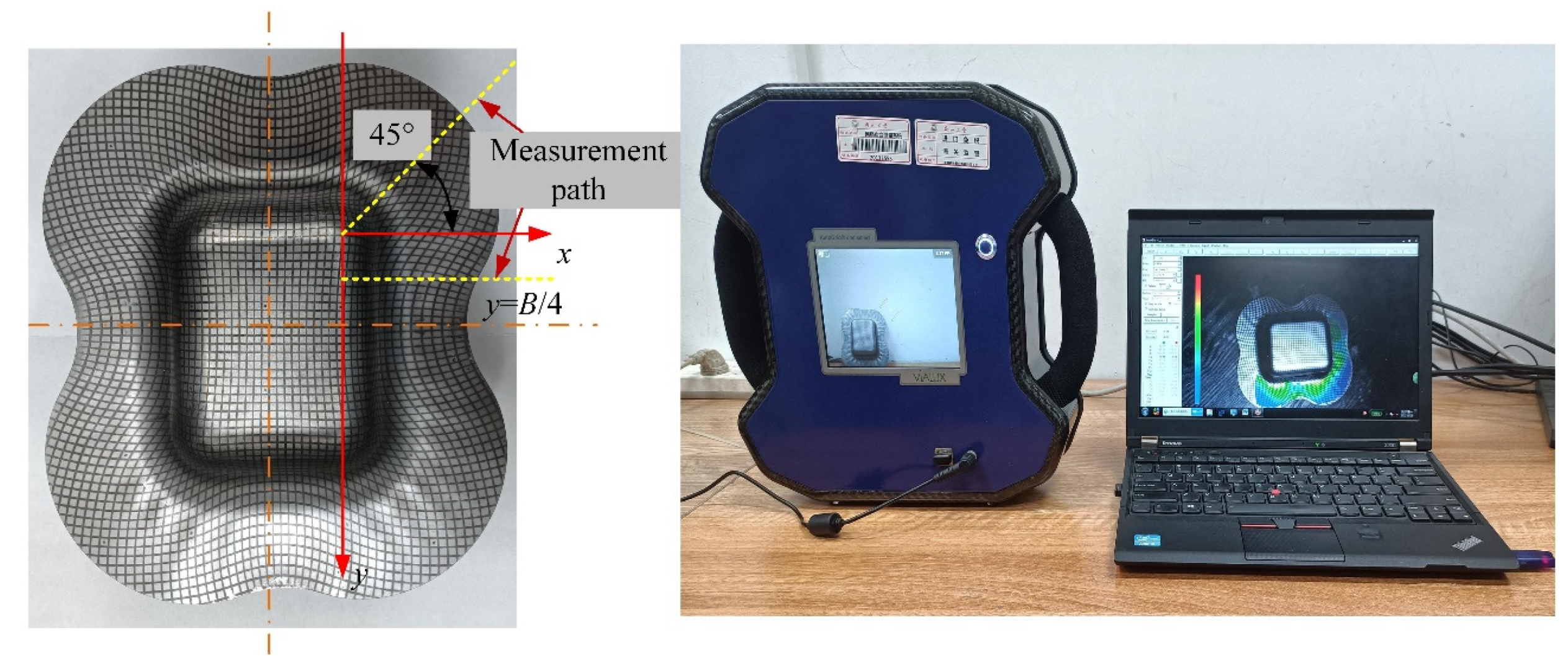
3.2. Experimental Procedure

The box-shaped drawing tests were carried out on a 500 T hydraulic press in the laboratory using SUS 304 stainless steel cold rolled with a thickness of 0.8 mm. The shape of blank and size of die are shown in Figure 4.
The drawing speed during forming process was 30 mm/min, polyethylene film was adopted for lubrication and the test equipment is shown in Figure 5. Butterfly springs were employed to provide blank holder force to control the blank holder during the tests. Butterfly springs were calibrated for spring stiffness by compression testing, deformed at 75% of the maximum compression to prevent springs damage and accurate blank holder force was obtained by accurately measuring the spring compression. In order to obtain the strain distribution law of formed parts, the original blank was carved with a 2.5 mm × 2.5 mm square grid on the surface through an electro-erosion method before the forming tests. The strain distribution law was measured by AutoGrid Compact grid strain measurement instrument (Chemnitz, Germany) after forming.

3.3. FE Simulation

During the process tests, only the strain distribution after deformation can be measured and no stress data can be obtained. Therefore, the evaluation of the stress calculation accuracy in the theoretical model needs to be combined with FE simulation. In this paper, ABAQUS FE simulation software was employed to simulate the deep drawing process of the box parts. In order to ensure simulation accuracy, the overall model was adopted for modeling. The material model was consistent with the material used in deep drawing tests. The anisotropy coefficients and real stress–strain relationships were derived in the above section. In FE simulation, die was set as a discrete rigid body and metal sheet was meshed with solid C3D10M, which is a kind of tetrahedral element. PE film lubrication was adopted in the tests. The authors in reference [19] performed a lot of tests on the coefficient of friction of the sheet under PE film lubrication conditions and the coefficient of friction was taken as its average value of 0.0828 in the numerical simulation and theoretical calculation in this paper. During the simulation, the female die was fixed, the blank holder was controlled using constant force and the punch moved downward at a constant speed. The shapes, sizes and boundary conditions were consistent with process tests. The simulation model is shown in Figure 6.

4. Results Analysis

A box-shaped part with dimensions of 60 × 80 mm and height of 35 mm was obtained by process test under 30 kN blank holder force. In order to facilitate the measurement, as shown in Figure 7, the 45° bisector of the corner area was selected as the measurement path in the corner area and a line parallel to the x-axis at y = B/4 was chosen as the measurement path in the straight-edge area. Strain distribution of the data points on measured path was extracted by taking pictures employing the AutoGrid Compact grid strain measurement instrument. The shape profile parameters, such as Rw, R(θ) and L(y), in the theoretical calculation model are difficult to derive theoretically and the measured data for the formed part were used in the calculation process.
The equivalent strain along the straight line y = B/4 and the 45° bisector path in the corner area of formed parts were extracted, respectively, as shown in Figure 8. The equivalent strain variation in the straight-edge area gradually increases from the inner edge to the outer edge; theoretical calculation results and experimental results show the same trend. The induced shear stress existing in the flange area during the deep drawing process of box-shaped parts leads to uneven material flow, with the fastest flow rate near the middle line of the straight-edge area. At the outer edge of the formed part, a concave contour appears in the middle of the straight-edge area and equivalent strain is the largest. In the corner area, the distribution of equivalent strain is similar to that of cylindrical drawing and the trend is gradually decreasing from inside to outside. At the outer edge of the center line of the straight-side area and the corner area near the entrance of the die, compressive stress is higher, material flow resistance is higher and material buildup thickening is serious. Plane strain is assumed in the theoretical model to simplify the calculation, while the effect of profile is ignored, which led to calculation errors—the closer to the outer edge of the blank, the larger the error of the theoretical calculated value compared to the experimental value, with a maximum average error of 15.9%.
The radial and tangential stresses at the measured path nodes in the straight-edge area of the FE model at the time of forming height 35 mm under the condition of 30 kN blank holder force were extracted and their distribution characteristics and theoretical calculation results are shown in Figure 9. The radial stress in straight-edge area is tensile stress, which gradually decreases from the inner edge to the outer edge, and the theoretical calculation results are quite close to the simulation results. The tangential stress is compressive stress; its absolute value increases gradually from the inner edge to the outer edge and the difference between the theoretical and simulated results of tangential stress at the outermost edge increases. In order to improve the applicability of the theoretical model to a variety of materials, the commonly used Hollomon hardening model is employed in this article, which belongs to a convex curve. As the strain increases, the gradient of stress increment becomes smaller, which produces an error with the real hardening law of some materials—the larger the strain, the greater the relative error produced. In addition, the inward concave profile near the midline of the straight-edge area makes the assumed linear variation law of equivalent strain in error with the actual one, resulting in a discrepancy between the theoretical calculation results and FE simulation results, with a maximum average discrepancy of 20.9%.
In the FE model, the radial stress and tangential stress directions of measurement path in the corner area are not in the principal coordinate system, so it is difficult to acquire the stresses in these two directions directly. Hence, the equivalent stress in the measurement path in the corner area was extracted and compared with the theoretical calculation results in this paper.
The equivalent stress distribution in the FE simulation and theoretical calculation on the measured path in the corner area are shown in Figure 10. The equivalent stress of FE simulation is greater than the theoretical calculation value in the first half of the measurement path in the corner area, while the latter half is the opposite. The curve for the power exponential strengthening model is upwardly convex. The fitted curve is higher than the true stress–strain curve when strain is small, while the gradient of stress increase in the fitted curve starts to fall below the true stress–strain curve when strain increases to a certain value. From Figure 8b, it can be seen that the equivalent strain in the corner area gradually decreases from the inner edge to the outer edge along the measurement path, which reflects that the theoretically calculated stress value is less than the simulated value in the first half of the measurement path where the strain is larger. The theoretical value at the outer edge with small strain is greater than the numerical simulation value, with an average difference of 16.9%. This illustrates the high sensitivity in the theoretical calculation accuracy to material mechanics models.

5. Conclusions

(1)
In order to investigate the material flow law in the flange area during the forming process of box-shaped parts, it is assumed that the deformation characteristics of the mass point on the zero line of shear stress in the corner area are equivalent to the deformation of axisymmetric parts. The expressions of stress, strain and induced shear stress coefficient in each part of the flange area are derived by applying the associated solution of equilibrium differential equation and yield condition.
(2)
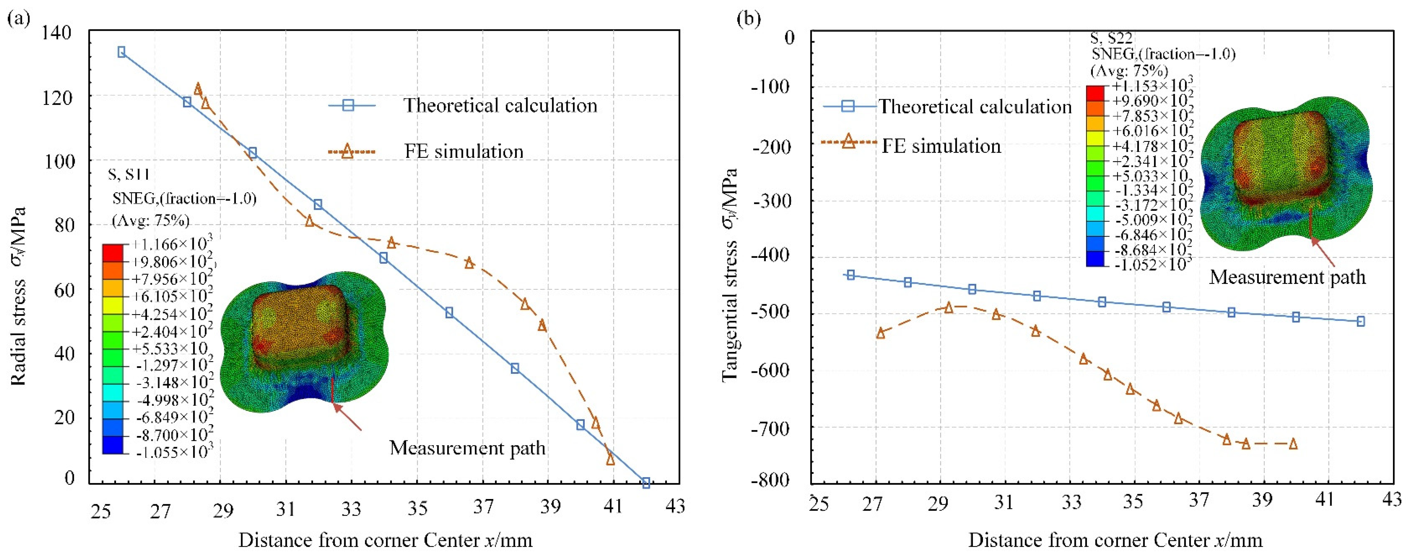
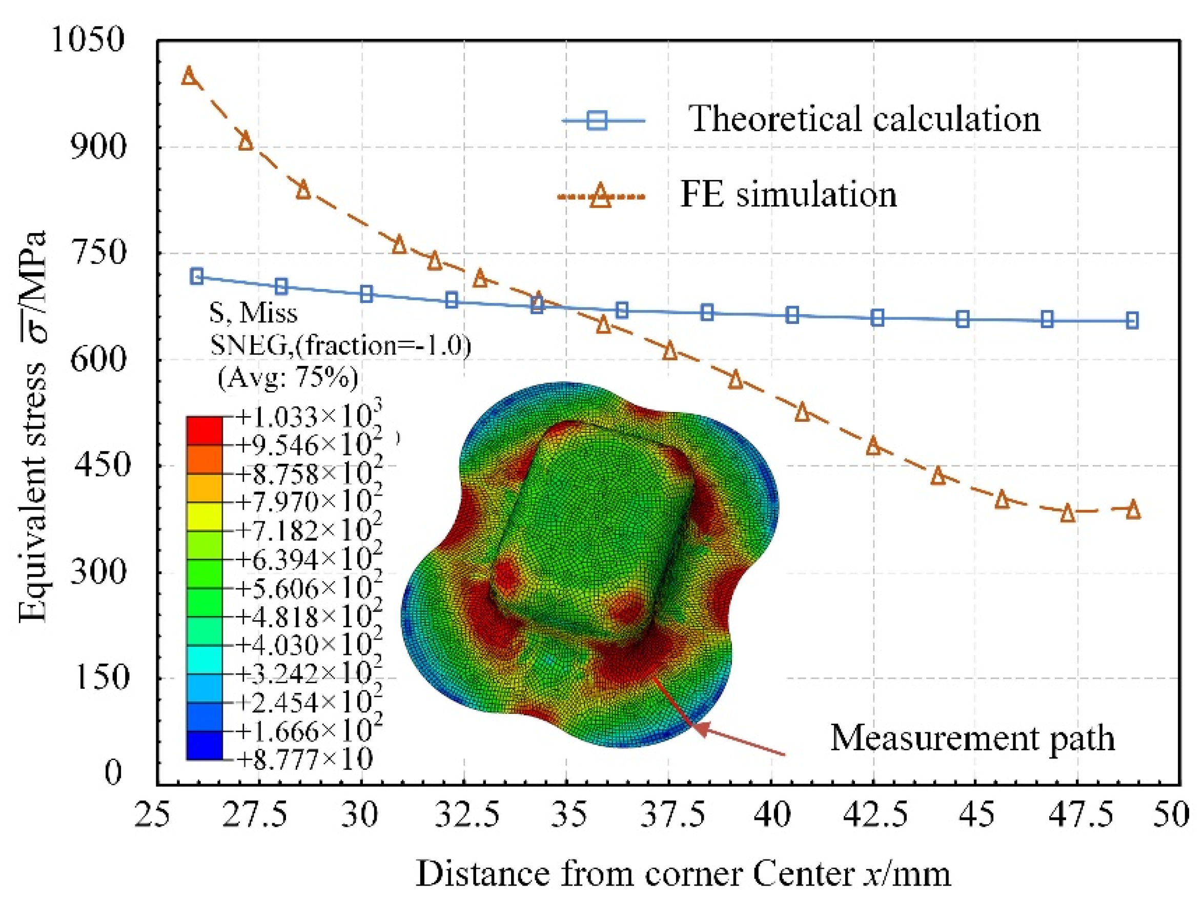
Under the same process conditions, the results of theoretical analysis are compared and analyzed by a box-shaped part deep drawing experiment and FE simulation. The results demonstrate that the variation trend for stress and strain obtained from the theoretical calculation are consistent with the process test and FE simulation, and the calculation accuracy of equivalent strain is higher than that of stress calculation. The theoretical calculation model provides a theoretical basis for the investigation of the deformation law, product design and optimization.
(3)
The accuracy in the theoretical calculation model is sensitive to the parameters in the material constitutive model. In this paper, a single exponential hardening model was used, causing some errors. Therefore, it is of great significance to adopt an appropriate material hardening model and obtain accurate model parameters to improve the accuracy of the theoretical analysis. In subsequent work, we will explore more advanced material models or segmented models to reduce the errors.

Author Contributions

Conceptualization, D.C. and C.Z.; methodology, D.C. and C.Z.; validation, X.C. and G.C.; formal analysis, D.C.; data curation, X.C. and G.C.; writing, D.C. All authors have read and agreed to the published version of the manuscript.

Funding

This research received no external funding.

Institutional Review Board Statement

Not applicable.

Informed Consent Statement

Not applicable.

Data Availability Statement

Not applicable.

Conflicts of Interest

The authors declare no conflict of interest.

References

  1. Chen, Y.-Z.; Liu, W.; Xu, Y.-C.; Yuan, S.-J. Analysis and experiment on wrinkling suppression for hydroforming of curved surface shell. Int. J. Mech. Sci. 2015, 104, 112–125. [Google Scholar] [CrossRef]
  2. Ghafar, A.A.; Abdullah, A.B.; Mahmood, J.I. Experimental and numerical prediction on square cup punch–die misalignment during the deep drawing process. Int. J. Adv. Manuf. Technol. 2021, 113, 379–388. [Google Scholar] [CrossRef]
  3. Pepelnjak, T.; Kayhan, E.; Kaftanoglu, B. Analysis of non-isothermal warm deep drawing of dual-phase DP600 steel. Int. J. Mater. Form. 2019, 12, 223–240. [Google Scholar] [CrossRef]
  4. Brabie, G.; Costache, E.M.; Nanu, N.; Chirita, B. Prediction and minimisation of sheet thickness variation during deep drawing of micro/milli parts. Int. J. Mech. Sci. 2013, 68, 277–290. [Google Scholar] [CrossRef]
  5. Yang, X.; Lang, L.; Liu, K.; Liu, B. Mechanics analysis of axisymmetric thin-walled part in warm sheet hydroforming. Chin. J. Aeronaut. 2015, 28, 1546–1554. [Google Scholar] [CrossRef] [Green Version]
  6. Lee, C.; Hong, S. Curvature area prediction for the deep drawing-ironing process of a cylindrical cup using finite element method and regression analysis. J. Mech. Sci. Technol. 2018, 32, 5913–5918. [Google Scholar] [CrossRef]
  7. Qin, S.J.; Gai, B.B.; Kong, S.H.; Deng. C. Analytical solutions of strain of axisymmetric curved part in sheet metal forming process using direct integral method. Int. J. Mech. Sci. 2015, 101, 49–58. [Google Scholar] [CrossRef]
  8. Shi, R.; Qin, S.J.; Zhang, Q.R.; Li, X.Y.; Chen, H.D. Analyses of axisymmetric drawing-bulging forming process of sheet metal using parametric and direct integral methods. J. Mater. Eng. Perform. 2022. [Google Scholar] [CrossRef]
  9. Guo, Z.; Men, Q.; Kang, X.; Junli, A. A stress analysis model of a cup-shaped part in a secondary deep drawing process. Int. J. Adv. Manuf. Technol. 2021, 116, 473–486. [Google Scholar] [CrossRef]
  10. Daxin, E.; Takaji, M. On the law of material flow deformation in a non-rotational symmetrical drawing. Chin. J. Mech. Eng. 2003, 39, 49–52. (In Chinese) [Google Scholar]
  11. E, D.X.; Takaji, M.; Wang, X.F. Stress analysis in box-shaped drawing for an integrity flange. China Mech. Eng. 2016, 17, 1306–1308. (In Chinese) [Google Scholar]
  12. E, D.X.; Takaji, M.; Li, Z.J. Stress analysis of rectangular cup drawing. J. Mater. Process. Technol. 2008, 205, 469–476. [Google Scholar] [CrossRef]
  13. Lang, L.H.; Wang, Y.M.; Xie, Y.S.; Xu, Y.Q.; Yang, Z.H.; Ma, H.J. The flange deformation characteristics and its effect on failure in the hydroforming process of aluminum alloy rectangular cup. Mater. Sci. Technol. 2013, 21, 37–43. [Google Scholar]
  14. Medellín-Castillo, H.I.; García-Zugasti, P.J.; Lange, D.F.; Colorado-Alonso, F.J. Analysis of the allowable deep drawing height of rectangular steel parts. Int. J. Adv. Manuf. Technol. 2013, 66, 371–380. [Google Scholar] [CrossRef]
  15. Rivas-Menchi, A.; Medellín-Castillo, H.I.; Lange, D.F.; García-Zugasti, P.J. Performance evaluation of analytical expressions for cylindrical and box-shaped deep drawing force estimation. J. Manuf. Process. 2018, 36, 340–350. [Google Scholar] [CrossRef]
  16. Ma, L.X.; Wang, F.Q.; Zhao, J. Approximate analysis of stress in main deformation area for a box-shaped box. Chin. J. Mech. Eng. 2005, 41, 56–61. (In Chinese) [Google Scholar] [CrossRef]
  17. Li, J.Q.; Jiang, S.F.; Wu, H.P.; Zhu, W.; Lu, C.D. Study on subsection variable blank holder force in deep drawing of rectangular parts. Mater. Res. Innov. 2011, 15, 230–233. [Google Scholar] [CrossRef]
  18. Wang, F.Q.; Zhao, J.; Guan, Y.P.; Ma, L.X. Analytical solution of stress in flanges during deep drawing for rectangular box. J. Harbin Inst. Technol. 2003, 35, 488–490. (In Chinese) [Google Scholar]
  19. Wang, C.; Ma, R.; Zhao, J. Calculation method and experimental study of coulomb friction coefficient in sheet metal forming. J. Manuf. Process. 2017, 27, 126–137. [Google Scholar] [CrossRef]
Figure 1. Schematic illustration of box-shaped part flange area.
Machines 10 00667 g001
Figure 2. Schematic illustration of cylindrical blank deformation.
Machines 10 00667 g002
Figure 3. FE simulation of box-shaped part drawing. (a) Cloud diagram of equivalent strain; (b) equivalent strain distribution of measurement path.
Machines 10 00667 g003
Figure 4. Dimensional specifications. (a) Blank size (mm); (b) die size.
Machines 10 00667 g004
Figure 5. Test equipment.
Machines 10 00667 g005
Figure 6. FE simulation model.
Machines 10 00667 g006
Figure 7. Strain extraction process.
Machines 10 00667 g007
Figure 8. Equivalent strain distribution (a) in the straight-edge area; (b) in the corner area.
Machines 10 00667 g008
Figure 9. Stress distribution in straight-edge area. (a) Radial stress; (b) tangential stress.
Machines 10 00667 g009
Figure 10. Equivalent stress distribution in the corner area.
Machines 10 00667 g010
Table 1. Chemical composition of SUS 304 (wt%).
CMnSiPSNiCrNFe
<0.08<2.00<1.00<0.045<0.0308.00–10.518.00–20.000.058Rem
Table 2. Mechanical properties parameters of SUS 304.
EσsKnr
195 GPa291 MPa1283.5 MPa0.3650.95
Publisher’s Note: MDPI stays neutral with regard to jurisdictional claims in published maps and institutional affiliations.

