Abstract
A turbo compressor was investigated to ensure the operational reliability of the charging of fuel cell systems. This study investigated air-lubricated herringbone bearings to support the high-speed rotating shaft. For reliable operation of the rotor bearing system, stable operation in the whole speed range (up to 120 krpm), as well as low lift-off speed, is an important issue. Some publications containing guidelines for an optimized design in terms of stability and lift-off behavior date back to the 1970s, with some simplifying assumptions (such as narrow groove theory and small eccentricity analysis). Many publications have addressed the calculations, as well as the optimization of herringbone-grooved bearings; however, general design guidelines are still missing in the view of the authors. Although the investigations related to bearings for the support of a lightweight rotor for a special compressor of a fuel cell unit, this study could also indicate favorable bearing designs for other high-speed applications. Here, the compressible Reynolds equation was solved in the whole solution domain using a conservative finite difference scheme, and the corresponding bearing characteristics were determined. In a perturbation analysis, the linearized dynamic coefficients of the herringbone bearing are calculated. To compare the suitability and performance of the various herringbone-grooved bearing designs, especially at high speed, the simple model of a Jeffcott rotor airborne with two identical herringbone-grooved journal bearings (HGJBs) was used. The geometrical parameters of the HGJBs were varied, and their effects on bearing characteristics and stability were evaluated. Recommendations concerning favorable geometrical bearing parameters for a sufficiently high stability threshold speed and reasonable low lift-off speed were the result of the parameter study.
1. Introduction
Aerodynamic or gas-lubricated bearings are applicable for the support of high-speed rotating shafts due to the low friction in the gas-lubricated film gap and the absence of contaminants in the lubricant. In general, foil bearings, segmented spring bearings, or spiral grooved bearings can be used. Spiral grooved bearings exhibited high load capacity; thus, spiral grooved bearings were the subject of the investigations. Herringbone-grooved journal bearings (HGJBs) generate a pressure field in the lubricating gap between the rotating shaft and the sleeve due to the pumping effect of the inclined grooves, as shown in Figure 1. Therefore, HGJBs always generate a pressure-build up depending on the speed, even for a concentric shaft position in the bearing sleeve, which differs from the performance of a plain journal bearing.
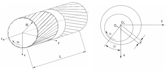
Figure 1.
Schematic of a herringbone-grooved bearing.
Consequently, herringbone-grooved bearings exhibit a higher stability threshold than plain journal bearings due to higher direct film stiffness for low shaft eccentricity. However, the bearing geometry has to be optimized to ensure the dynamic stability of rotor bearing systems for high-speed applications. The geometrical parameters to be optimized are the groove inclination angle, α, the groove depth ratio, tg/c, the groove width ratio, bg/(bg + bl), the dam length ratio, Ld/L (with L = Lg1 + Lg2 + Ld), and the number of grooves, k, as depicted in Figure 2.
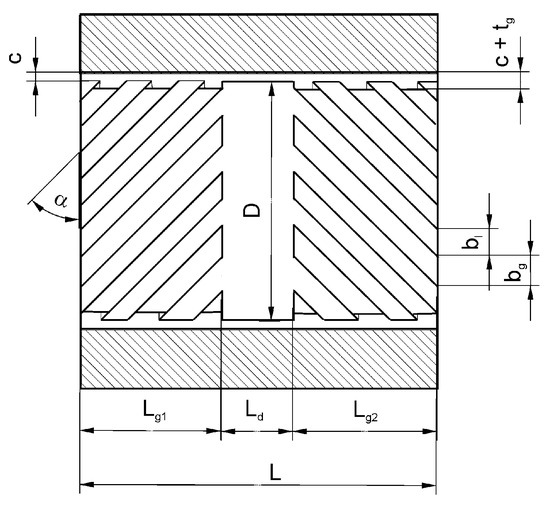
Figure 2.
Geometrical parameters of a herringbone bearing.
The static and dynamic performance of those gas-lubricated bearings can be described by the corresponding bearing characteristics, such as load capacity, frictional force, and stiffness and damping coefficients of the lubricating film. These values are determined based on the pressure distribution and perturbed pressure distribution in the bearing. This requires the solution of the (nonlinear) Reynolds equation, such as by applying the finite difference method or the finite element method. For shaft vibrations with small vibration amplitudes compared with the clearance, a small-perturbation analysis can be applied to compute the linearized stiffness and damping coefficients of the lubricating gap by solving the first-order perturbation equations. For discretizing the solution domain, a rather fine grid is required to describe the spiral groove geometry. As investigations on the effect of the number of grooves on bearing characteristics have shown, bearing characteristics are only subject to small changes from changes in the groove number, provided the groove number is fairly high, i.e., 16 grooves or higher [1].
In this case, the effect of groove number on the bearing characteristics can be neglected and the so-called narrow groove theory (NGT) can be applied as an approximation. The pressure distribution over the groove–land region is approximated using linear functions for the pressure distribution over the groove and land in the circumferential direction.
This theory originated from Whipple [2] regarding the spiral-grooved thrust bearing. On that basis, Vohr and Pan [3] extended the theory toward spiral-grooved journal bearings. To solve the equations, Vohr and Chow [4] presented the small-eccentricity perturbation theory to calculate the pressure distribution using a Runge–Kutta method. Cunningham et al. [5] measured the load capacity, bearing stiffness, and displacement angles of herringbone bearings. As could have been expected, the agreement between measurement and small-eccentricity analysis is quite good for low eccentricity, up to ε = e/c = 0.3 (with eccentricity e and clearance c), and for a rather low compressibility number Λ.
Fleming [6] extended the small perturbation theory to account for an additional aerostatic pressure generated by orifices. Cunningham et al. [7] measured the static performance characteristics of herringbone-grooved gas bearings, such as the load capacity, eccentricity, attitude angles of the shaft, and power loss. The maximum load capacity was measured for a herringbone bearing with α = 30°, 20 grooves, c ≈ 10.7 μm, tg = 14.7 μm, and hmax/hmin ≈ 2.35.
By balancing the mass streams in the circumferential and axial directions and by assuming averaged, linear pressure gradients on the groove and land, Pan and Malanoski [8] derived a corresponding Reynolds equation for a herringbone journal bearing with an infinite number of grooves and investigated the bearing stability through small perturbation analysis.
Fleming and Hamrock [9] presented an optimization procedure concerning the geometrical bearing parameters for maximum bearing stability based on the small eccentricity analysis conducted by Vohr and Chow [4]. For a length-to-diameter ratio L/D = 1, they found an optimum film thickness ratio H = (tg + c)/c between 2.25 and 2.77 and an inclination angle α between 24.2°and 36.2°, depending on the speed. For the following quantities, only intervals are given for the optimum groove width ratio (between 0.48 and 0.6) and optimum groove length ratio (between 0.904 and 1).
Bonneau and Absi [1] investigated a herringbone bearing with four grooves by solving the Reynolds equation (linearized with the Newton–Raphson procedure) through FEM. Bearing characteristics were calculated for a grooved shaft against a smooth sleeve as well as for a smooth shaft against a grooved sleeve. For different values of groove depth, groove inclination angle, and the number of grooves, the stiffness coefficients and the load capacity of the bearing are presented. Faria [10,11] applied FEM and the Galerkin-weighted residual method for solving the Reynolds equation and the corresponding perturbed differential equation to calculate the performance characteristics of the same herringbone-grooved bearing. The results of this high-order FEM agree well with the data obtained by Bonneau and Absi for the considered herringbone bearing.
Jang and Yoon [12] derived the Reynolds equation for both cases of smooth shafts running in grooved sleeves and grooved shafts running in smooth sleeves. The frictional power loss was significantly higher for smooth shafts running in grooved sleeves than in the case of grooved shafts in smooth sleeves.
Stanev, Wardle, and Corbett [13] used the calculations derived by D. P. Fleming [6] and extended them to hybrid herringbone-grooved bearings with an additional pressure build-up through orifices.
Here, only publications that focused on the optimization of the herringbone-grooved bearing concerning lift-off and stability behavior were considered.
Zirkelback and San Andres [14] calculated the bearing characteristics with FEM and investigated the effect of geometrical bearing parameters on the dynamic coefficients and the stability of the bearing.
Yoshimoto, Miyatake, Nagata [15], and Tomioka and Miyanaga [16] show that flexible sleeve support can significantly improve stability. Tomioka and Miyanaga [16] presented stability charts for HGJBs with varied parameters of external spring coefficients and external damping ratios.
Schiffmann [17] performed a Pareto optimization procedure for bearing parameters concerning stability. Combinations of bearing parameters are given herein, resulting in a highly stable operational domain for the bearing.
Fujita [18] shows that a higher L/D ratio contributes to improved stability and that a higher film thickness ratio H = (tg + c)/c ≈ 3 is more favorable than lower values of H. It has also been stated that a groove inclination angle of 30° is preferable for high bearing stability.
Miyanaga and Tomioka [19] considered the centrifugal effects and investigated the effect of the groove depth ratio, tg/c, and groove width ratio, bg/(bg + bl), on the bearing stability for different values of dimensionless rotor mass. They show that a groove width ratio bg/(bg + bl) between 0.3 and 0.5 and groove depth ratio (tg + c)/c between 1.5 and 2 resulted in a high stability threshold speed, which exhibited a maximum in the mentioned parameter ranges.
Guenat and Schiffmann [20] performed a multi-objective optimization of the bearing parameters for maximum stability, which generated a safety margin so manufacturing uncertainties did not significantly affect the stability. Depending on the film–thickness ratio, optimum values of groove width ratio, groove inclination angle, groove depth, and groove length ratio were identified [20].
Iseli et al. [21] evaluated the static and dynamic properties of spiral-grooved gas journal bearings as well as the critical rotor mass by using the NGT and the FEM. For the technically important case of rotating grooves, they made a time-periodic approach (finite groove approach) to eliminate the computationally expensive time dependency. For higher eccentricities ε > 0.4 and compressibility number Λ > 5 the deviations of critical mass calculated according to NGT and with FEM become significant, especially for a small number of grooves.
Iseli and Schiffmann [22] optimized the geometrical parameters of the herringbone-grooved gas bearing for maximum load capacity and maximum stability for four different rotor designs. They calculated the critical mass and critical transverse moment of inertia for each rotor-bearing system with a full time-integrated transient analysis and compared the results with those obtained with a linearized method by using linearized bearing coefficients. The linearized method underpredicts the critical mass and the critical transverse inertia moment with a deviation of less than 7% compared to the transient analysis [22]. The deviation of the unbalance response between the linearized method and the transient analysis is less than 6% for maximum amplitudes of ε < 0.5 and less than 8% for amplitudes ε < 0.7 [22].
The objective of this work was to optimize the bearing parameters of the aerodynamic herringbone-grooved bearing for application in the air compressor of a fuel cell in terms of load capacity and system damping to achieve low lift-off speed and a high stability threshold speed.
2. Analysis
Two methods are mainly applied to numerically calculate the pressure distribution in aerodynamic herringbone-grooved bearings [17]. One method consists of solving the discretized Reynolds equation by applying a finite element or finite difference method and using a grid mesh with a film thickness distribution reflecting the real groove geometry. This requires a corresponding fine mesh to accurately describe the real spiral groove pattern. Another method based on the assumption of an infinitely high number of grooves is the so-called narrow groove theory (NGT), which does not require a fine mesh for the solution with the finite difference method; therefore, it is expected to be much faster and rapidly converging when iterating the shaft position (ε-γ-iteration) and calculating the corresponding pressure profile in the bearing. With this approach, the circumferential saw-toothed pressure profile is locally approximated by a linear pressure distribution over the groove and land region, which corresponds to the real distribution for an infinite number of grooves and is a good approximation for a fairly high number of grooves.
The time for calculating the pressure distribution with the conservative finite difference method and the resulting bearing characteristics is also quite reasonable with a fully developed model which describes the real groove geometry almost exactly through the use of an appropriate computational grid and is, therefore, superior to the NGT-model. In addition, the effect of the groove number can be investigated, which is not possible with the NGT. Especially for low numbers of grooves in herringbone bearings, the narrow groove theory does not seem to be sufficiently accurate.
2.1. Stationary Reynolds Equation
The Reynolds equation for gas lubricants, considering the velocities of both bearing surfaces in journal bearings, is as follows [23,24]:
Laminar flow and ideal gas behavior are assumed here. Laminar flow is valid as long as there are no flow instabilities, which is true as long as Ta < Tac so that Taylor vortices are not likely to occur [25]. This condition is true for:
So, turbulence effects are negligible if the local Reynolds number in the grid points of the solution domain is below the critical Reynolds number Rec (corresponding to the critical Taylor number Tac ≈ 41.1 [25]). The Reynolds number—with the actual bearing parameters (R = 0.0125 m and c = 12 μm) and operational parameters—is about one-tenth of Rec.
Furthermore, slip flow is not considered, because the actual Knudsen number, Kn = λ/h, is certainly below the critical value Knc = 0.01 for air at an operating temperature not higher than 400 K (with mean free path λ ≤ 0.10 μm) [26] and for clearance of c = 12 μm; thus, the Reynolds Equation (1) can be regarded as valid as long as these conditions are fulfilled.
The Reynolds Equation (1) can be applied to both cases of grooved journals against smooth sleeves and smooth journals against grooved sleeves. The x coordinate axis is fixed to the stationary part; therefore, the Reynolds equation shown above applies to herringbone-grooved bearings with (stationary) grooves in the sleeve with U2 = ω∙R; U1 = 0 (Figure 3).
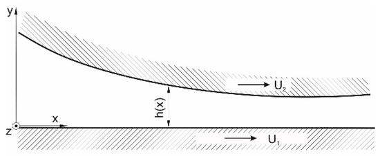
Figure 3.
Bearing surface coordinate axes and length scales.
For manufacturing reasons, grooves are commonly positioned on the rotating shaft. As described by Jang and Yoon [27] the “film thickness changes as the grooved journal rotates […]. Introducing the assumption that the grooved journal is stationary and the sleeve is rotating in the opposite direction, the rate of change of the fluid film can easily be treated numerically” [27] p. 298. In this case, the surface velocities become U2 = 0, U1 = −ω∙R.
Introducing θ for the circumferential angular coordinate, Z = z/R for the dimensionless axial coordinate, H = h/c as the dimensionless gap height, and P = p/pa as the dimensionless pressure (also assuming ideal gas behavior and a laminar gas film [28]), the Reynolds equation [23] becomes:
compressibility number ; ;
squeeze number (ν: excitation frequency);
dimensionless axial coordinate Z = z/R;
dimensionless time coordinate Φ = ν∙t (ν: excitation frequency).
The boundary conditions are as follows:
In both cases—grooves stationary on the sleeve or grooves on the rotating shaft—were considered in the publication by Jang and Yoon [27], but only the latter case was treated in this study for practical reasons because the grooves are easier to manufacture on the shaft rather than on the sleeve. The Reynolds equation is an elliptic differential equation and is nonlinear due to the compressibility effect.
For linearization, the Newton–Raphson method is applied. The Reynolds equation is then numerically solved by applying the conservative finite difference method. To this end, the entire solution domain was discretized with a 2D model (shown in Figure 4) and the Reynolds equation was solved to calculate the pressure profile for stationary operation.
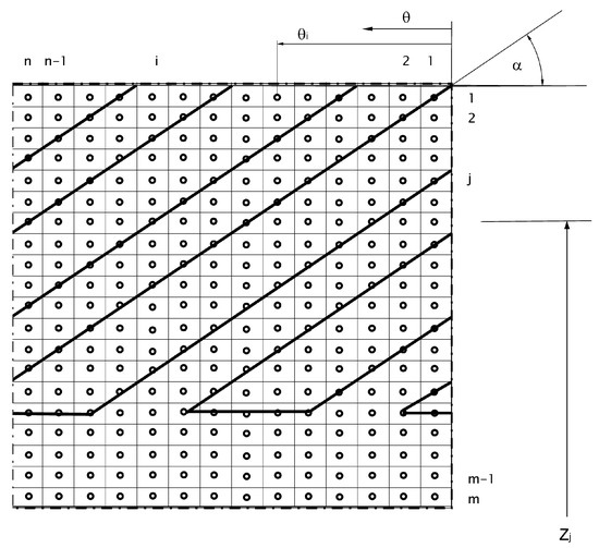
Figure 4.
Section of the computation grid representing half-width of a symmetrical HGJB.
2.2. Perturbation Analysis
The dynamic coefficients, i.e., the stiffness and damping coefficients, can be calculated by performing a small perturbation analysis if the vibration amplitudes are small compared with the minimum film thickness. For completeness of the report, the basic approach is presented subsequently.
Accounting for small deviations in eccentricity Δε and displacement angle Δγ, the film thickness H becomes [28] (for definitions of x, y, and γ, see Figure 1):
Here, H0 denotes the stationary dimensionless gap height, and H1∙x and H2∙y denote its perturbations. For synchronous vibrations of the shaft, x and y represent the real parts and , respectively, and represent the corresponding displacement speed of the shaft. The corresponding perturbed pressure can also be written according to the linearized Taylor approach [28]:
The resulting partial differential equations for the zeroth-order pressure and film thickness perturbations are the ordinary Reynolds equation, presented above, and the differential equation for the first-order perturbations [28]:
2.3. Stability Analysis
The dynamic characteristics of the rotor-bearing system are affected by the stiffness and damping coefficients of the bearing. The (rigid) airborne Jeffcott rotor in two identical bearings was taken as a basis and the first two natural frequencies and the corresponding damping of the natural vibrations were calculated herein, as presented in Figure 5. Although the assumptions concerning the rotor model (symmetrical rotor, neglect of gyroscopic effects) are very restrictive, the suitability of different bearing designs can be evaluated regarding the stability threshold and compared with each other. The stability threshold for the real rotor-bearing system can differ considerably from the values evaluated for the symmetrical Jeffcott rotor-bearing system. This model is nonetheless a helpful means to find optimized geometrical bearing parameters concerning bearing stability.

Figure 5.
Model of an airborne rotor for linear stability considerations.
The direct stiffness of aerodynamic bearings is much lower than the bending stiffness of a rotor; therefore, the rotor can be assumed to be rigid. Thus, it is sufficient to take the resulting bearing stiffness and damping coefficients, kik and cik, respectively, and the rotor mass, msh, as a basis for the stability analysis [28].
The shaft motion equations have been derived from the force balance between the inertia, spring, and damping forces on one hand, and the resulting external force on the other hand. Here, the following definitions are introduced [28]:
and
with gravity, g, unbalance radius, ρ*, ambient pressure, pa, stiffness coefficient, kik, and damping coefficient, cik, of the lubricating film.
The equations of motion in x- and y-directions for unbalanced excitation with angular velocity, ω, are [28]:
Here, the angular velocity, (with c representing the radial clearance of the bearing), is introduced to define the dimensionless quantity, ω/ω0. To calculate the natural frequencies and the system damping, only the homogeneous equations (right-hand side set equal to zero, see equations above) are used. Harmonic motion is assumed with:
The complex eigenvalue i consists of the real part −Ui = −ui/ω, with Ui representing the dimensionless damping and the imaginary part, Vi = vi/ω the dimensionless natural frequency ωei*/ω. The homogeneous equations of motion can be expressed in matrix form:
Nontrivial solutions can be found, provided that the system determinant vanishes:
This results in a quartic equation; thus, four eigenvalues i can be determined. By solving the characteristic equation, the frequency ωei* = vi and the damping ui of the two natural oscillations of the system are obtained for a given speed.
The system damping, Di, is then calculated, inserting the value, ui, and the corresponding value, vi [28]:
In the following the minimum system damping DS is calculated by inserting the minimum value ui and the corresponding value vi.
System damping ordinarily decreases with increased rotor speed [28]. When the system damping vanishes, the stability threshold speed is reached with an onset of strong subsynchronous vibrations.
3. Results
After verification with data presented in the literature, an optimization procedure was performed and the corresponding results regarding lift-off speed and stability threshold are presented. Herein, ambient pressure, pa = 0.1 bar, was always assumed.
3.1. Verification
The following investigations refer to a symmetrical herringbone bearing, as depicted in Figure 1 and Figure 2. The load capacity of a herringbone-grooved bearing (with a smooth rotating shaft and a grooved sleeve) was calculated for different dimensionless eccentricities, ε = e/c. The results match well with the data of Faria [11] for the compressibility number Λ = 15.3 and—for moderate shaft eccentricities up to ε = 0.5—also for Λ = 100; for Λ = 100 and eccentricities above ε = 0.5, the agreement is still satisfactory, as shown in Figure 6.
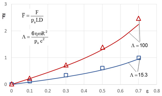
Figure 6.
Load capacity of a herringbone bearing (α = 30°, bg/(bg + bl) = 0.5; Lg/L = 1; tg/c = 1.4; c = 10 μm, 4 grooves in the sleeve, smooth shaft): numerical results obtained by Faria (data from [11], symbols) and this study’s results (lines).
The direct stiffness coefficients, calculated by Bonneau and Absi for an HGJB with four grooves, agree quite well with our results, depicted in Figure 7.
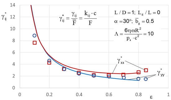
Figure 7.
Direct stiffness coefficients: results from Bonneau and Absi (data from [1], symbols) and this study’s results (lines).
The stiffness coefficients of the radial spiral groove bearing (D = 0.04 m; L = 0.04 m; c = 10 μm; tg = 14 μm; α = 30°; .5; kg = 4) calculated by Faria with FEM [10] are in satisfactory agreement with our values, depicted in Figure 8.
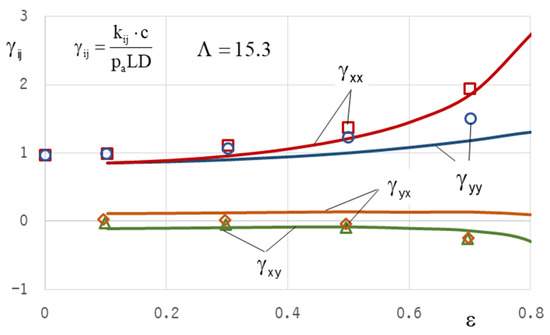
Figure 8.
Stiffness coefficients: results from Faria (data from [10], symbols) and this study’s results (lines).
3.2. Variation in Bearing Parameters
The geometrical bearing parameters were varied to develop a favorable design for achieving a low lift-off speed and high stability threshold speed. Lift-off speed is reached during start-up when the rotor is no longer operating in the mixed friction region but is airborne by the lubricant. The stability threshold speed is defined by the rotor speed causing the system damping to become zero. System damping decreases with increasing speed, showing a diminishing low value or even zero at the stability threshold speed. For stable operation, the stability threshold speed should be significantly higher than the maximum operating speed, which, in our case, is nmax = 120 krpm for application in a compressor for a fuel cell.
The bearing geometry, as well as the operating parameters (bearing load and speed), have a considerable impact on the bearing characteristics. The parameters to be optimized regarding lift-off speed and stability threshold speed are the groove inclination angle, α, the circumferential groove width ratio , the dam length ratio , the clearance c, the groove depth tg, and the number of grooves k. The ratio of bearing length to diameter was kept constant at L/D = 1 and the bearing radius was R = 0.0125 m.
3.2.1. Effect of Bearing Parameters on Lift-Off Speed
The minimum film thickness, hmin, is a measure of pressure build-up in the aerodynamic bearing. For a certain load, the minimum film thickness is expected to be higher for optimized spiral groove patterns, producing higher pressures for a certain film gap height. As can be seen in Figure 9, the spiral groove patterns with low groove inclination angles operate at a higher film thickness than those with a higher groove inclination angle. It can be concluded that spiral groove patterns with low groove inclination angles have an advantage over higher inclination angles in terms of lift-off speed.
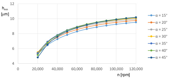
Figure 9.
Minimum film thickness in the herringbone bearing for various groove inclination angles (tg = 17.5 μm; c = 12 μm; g = 0.5; Ld/L = 0.02; 20 grooves; F = 10 N).
Figure 10 shows that the groove width ratio, g, hardly affects the minimum film thickness, hmin, in the range 0.3 ≤ g ≤ 0.6. The dam length ratio, Ld/L, has only a slight effect on the minimum film thickness (Figure 11), whereas the groove inclination angle has a much greater impact on the pressure build-up, which is higher for low values of α (α = 20°) than for α = 40° at rotor speeds below 25,000 rpm.
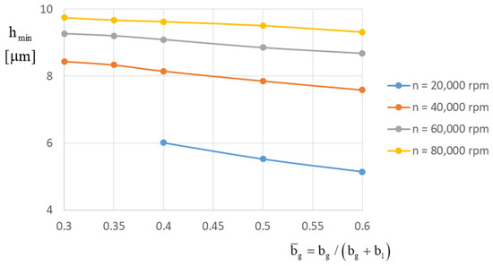
Figure 10.
Effect of the groove width ratio on the minimum film thickness in herringbone bearings (tg = 17.5 μm; c = 12 μm; α = 30°; Ld/L = 0.02; 20 grooves; F = 10 N).
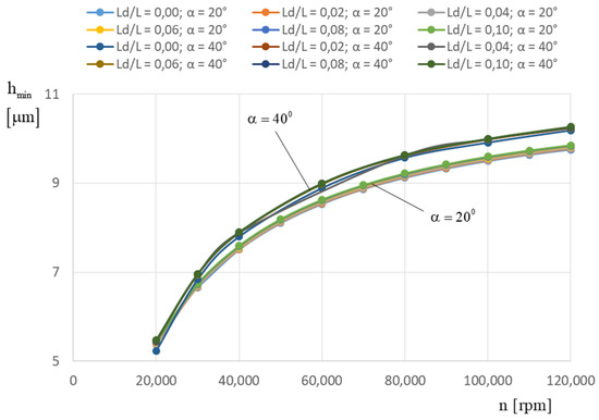
Figure 11.
Effect of the groove inclination angle and dam length ratio on the minimum film thickness (tg = 17.5 μm; c = 12 μm; g = 0.5; 20 grooves; F = 10 N; Ld/L = 0 … 0.10).
3.2.2. Effect of Bearing Parameters on the Stability Threshold
The geometrical parameters of the symmetrical herringbone bearing include the groove inclination angle, α, the groove width ratio, g, the dam length ratio, Ld/L, the groove depth ratio, tg/c, and the number of grooves, k. The groove depth ratio, tg/c, was kept constant with tg/c =1.45, which is nearby the optimum value of 1.54 for Λ = 10 and 2.0 for Λ = 20 (after [9]) in terms of stability.
The bearing load was kept constant at F = 2 N, which corresponds to the stationary bearing load due to the rotor weight of the specific application in the fuel cell compressor according to the requirements in the Ariel project. The influence of the bearing parameters on the system damping DS was investigated for the maximum operating speed of n = 120 krpm.
From Figure 12, Figure 13, Figure 14, Figure 15 and Figure 16, it can be observed that the system damping, DS, increases with the grove inclination angle, α, at least in the range 30° ≤ α ≤ 40° for = 0.5, reaching even higher values at α = 45° and = 0.4 for 0.0 ≤ Ld/L ≤ 0.08. Nearly the same has been found for Ld/L = 0.1, except for the fact that here the maximum DS is reached for α = 45° and = 0.5, as demonstrated in Figure 17.
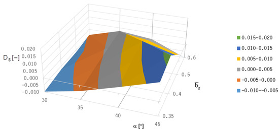
Figure 12.
Effect of the groove inclination angle and groove width ratio on the system damping of a Jeffcott rotor with HGJBs (Ld/L = 0.0; c = 12 μm; tg = 17.5 μm; 20 grooves; F = 2 N; n = 120 krpm).
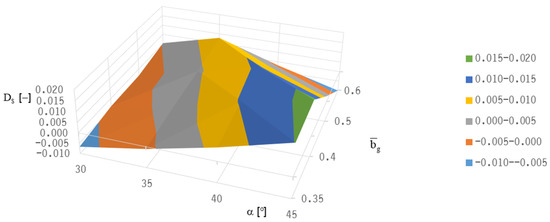
Figure 13.
Effect of the groove inclination angle and groove width ratio on the system damping of a Jeffcott rotor with HGJBs (Ld/L = 0.02; c = 12 μm; tg = 17.5 μm; 20 grooves; F = 2 N; n = 120 krpm).
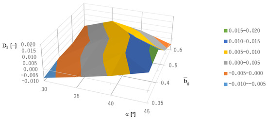
Figure 14.
Effect of the groove inclination angle and groove width ratio on the system damping of a Jeffcott rotor with HGJBs (Ld/L = 0.04; c = 12 μm; tg = 17.5 μm; 20 grooves; F = 2 N; n = 120 krpm).
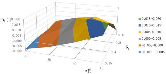
Figure 15.
Effect of the groove inclination angle and groove width ratio on the system damping of a Jeffcott rotor with HGJBs (Ld/L = 0.06; c = 12 μm; tg = 17.5 μm; 20 grooves; F = 2 N; n = 120 krpm).
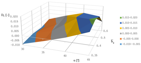
Figure 16.
Effect of the groove inclination angle and groove width ratio on the system damping of a Jeffcott rotor with HGJBs (Ld/L = 0.08; c = 12 μm; tg = 17.5 μm; 20 grooves; F = 2 N; n = 120 krpm).
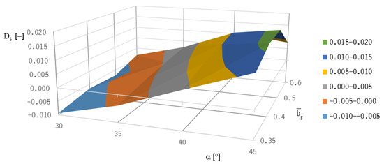
Figure 17.
Effect of the groove inclination angle and groove width ratio on the system damping of a Jeffcott rotor with HGJBs (Ld/L = 0.1; c = 12 μm; tg = 17.5 μm; 20 grooves; F = 2 N; n = 120 krpm).
In Figure 18, the strong effect of the groove inclination angle, α, on the system damping is visible, showing a maximum value at α = 40° (for Ld/L ≤ 0.06) or at α = 45° (for 0.08 ≤ Ld/L ≤ 0.1), respectively. The effect of Ld/L itself on the system damping is quite low, showing a relative maximum at Ld/L = 0.02 for α < 40°, as depicted in Figure 18. In contrast, the effect of the groove depth ratio, tg/c, on the system damping is rather strong (Figure 19), exhibiting maximum system damping for high Λ-values at tg/c = 1.46.
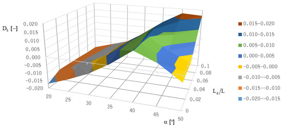
Figure 18.
Effect of groove inclination and dam length ratio on the system damping of a Jeffcott rotor with HGJBs (; tg = 17.5 μm; c =1 2 μm; 20 grooves; F = 2 N).
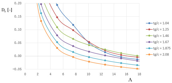
Figure 19.
Effect of the groove depth ratio, tg/c, and compressibility number on the system damping of a Jeffcott rotor with HGJBs (; α = 40°; Ld/L = 0.02; 20 grooves; F = 2 N).
The number of grooves significantly affects the system damping only at Λ-values above Λ = 15. As can be seen in Figure 20, the system damping tends to be higher for a lower groove number, k, as long as k ≥ 10 for a bearing load of F = 2 N.
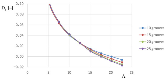
Figure 20.
Effect of the number of grooves and compressibility number on the system damping of a Jeffcott rotor with HGJBs (; α = 40°; Ld/L = 0.02; tg/c = 1.46; F/(paLD) = 0.032).
The system damping, DS, is not only affected by the compressibility number, but also by the bearing load, as shown in Figure 21 for HGJBs with the geometrical parameters presented herein and 15 grooves. At Λ ≈ 17.5 system damping is positive for values of the specific bearing load lower than . The substitution of HGJBs with 25 grooves would result in positive system damping only for the specific bearing load at Λ ≈ 17.5, as shown in Figure 22. However, the system damping is very low in these cases; thus, external damping is recommended to stabilize the rotor-bearing system.
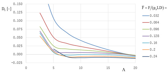
Figure 21.
Effect of the bearing load and compressibility number on the system damping of a Jeffcott rotor with HGJBs (; α = 40°; Ld/L = 0.02; tg/c = 1.46; 15 grooves).
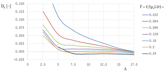
Figure 22.
Effect of the bearing load and compressibility number on the system damping of a Jeffcott rotor with HGJBs (; α = 40°; Ld/L = 0.02; tg/c = 1.46; 25 grooves).
4. Conclusions
The application of aerodynamic HGJBs in high-speed machines, such as fuel cell compressors, requires operational safety in the complete operational range. This means that stable operation must be ensured even at maximum operating speed; a low lift-off speed is also required in the low-speed range to avoid excessive wear during start-up and shutdown.
Both optimization targets—lift-off speed and stability threshold speed—lead to different “optimum” bearing designs because good lift-off behavior is realized with a low groove inclination angle (at about 20°), whereas stability can only be achieved with higher groove inclination angles (α = 40°).
The stable operation must always be ensured (representing a necessary condition); therefore, the focus of the optimization procedure was on optimizing the parameters for optimum stability, which was performed for the Jeffcott-rotor model in two identical HGJBs using positive system damping as a criterion.
To estimate the dynamic behavior of the real rotor-bearing system, the real rotor geometry has to be considered, with its real mass distribution and the inertia moments of the impellers, among other factors. The approach in this paper used linearized dynamic coefficients, which are useful for estimating the stability threshold speed. However, the rotor bearing behavior is nonlinear for operational points, where subsynchronous vibrations and larger vibration amplitudes occur. In this case, a transient analysis must be carried out to achieve a realistic simulation of rotor bearing performance.
Analysis of the transient behavior of the rotor bearing system will, therefore, be the focus of a follow-up project, which should also focus on the effects of external damping and aerostatic pressure supply (as an auxiliary lift-off device) on the stability of the system. Special attention will also be paid to real gas effects [29], because depending on the operating condition, the state of the lubricant in the air compressor of a fuel cell may be close to the saturation line. For other applications (with different geometrical bearing parameters and operational parameters), turbulence or rarefaction effects could become prevalent as well.
The present study was limited to the optimization of the geometrical parameters of a conventional herringbone-grooved bearing. Enhanced grooves or arc-shaped grooves have already been the subject of recent studies conducted by several researchers maximizing the load capacity and/or stability threshold of the bearing.
Author Contributions
Methodology, software, validation, formal analysis, investigation, H.S.; resources, data curation, H.S.; writing—original draft preparation, H.S.; writing—review and editing, M.S.; visualization, H.S.; supervision, C.H.; project administration, C.H.; funding acquisition, M.S. and C.H. All authors have read and agreed to the published version of the manuscript.
Funding
This research was funded by the German Federal Ministry of Transport and Digital Infrastructure, grant number 03B10105D.
Institutional Review Board Statement
Not applicable.
Informed Consent Statement
Not applicable.
Data Availability Statement
Data is contained within the article.
Acknowledgments
The authors gratefully acknowledge the support received from the German Federal Ministry of Transport and Digital Infrastructure in the project ‘Ariel’. Furthermore, we acknowledge the support from the Open Access Publication Funds of TU Braunschweig.
Conflicts of Interest
The authors declare no conflict of interest. The funders had no role in the design of the study, in the collection, analyses, or interpretation of data, in the writing of the manuscript, or in the decision to publish the results.
Nomenclature
| bg, bl | Groove width, land width (m) |
| Groove width ratio | |
| c | Clearance (m) |
| cik | Damping coefficient of the lubricating film (Ns/m) |
| Cik | Dimensionless damping coefficients Cik = ω·cik·c/(paLD) |
| D | Bearing diameter (m) |
| D* | Damping ratio |
| DS | System damping |
| e | Eccentricity (m) |
| F | Force (N) |
| Dimensionless force | |
| G | Gravity constant (m/s2) |
| H | Film thickness (m) |
| H | Dimensionless film thickness |
| kik | Stiffness coefficients of the lubricating film (N/m) |
| Kik | Dimensionless stiffness coefficients Kik = kik·c/(paLD) |
| Kn | Knudsen number Kn = λ/h |
| L, Ld, Ll | Bearing length (m), dam length (m), land length (m) |
| N | Speed (rpm) |
| p, pa | Pressure, ambient pressure (Pa) |
| P = p/pa | Dimensionless pressure |
| R | Rotor radius (m) |
| Re | Reynolds number Re = ρωRc/η |
| t | Time coordinate (s) |
| Ta | Taylor number Ta = Re∙ |
| tg | Groove depth (m) |
| x,y,z | Coordinates (m) |
| Z | Dimensionless axial coordinate Z = z/R |
| α | Groove inclination angle |
| γ | Displacement angle of the shaft |
| γik | Dimensionless stiffness coefficients (from the literature) |
| ε | Dimensionless eccentricity ε = e/c |
| η | Dynamic viscosity (Pa·s) |
| θ | Angular coordinate (rad) |
| λ | Mean free path (m) |
| (Complex) eigenvalue | |
| ν | Excitation frequency (s−1) |
| Λ | Compressibility number |
| ρ | Density of gaseous lubricant (kg/m3) |
| ρ* | Eccentricity of the center of gravity (m) |
| σ | Squeeze number |
| ω | Angular shaft velocity (rad/s) |
| Subscripts | |
| a | Ambient |
| d | Dam |
| g | Groove |
| l | Land |
| min, max | Minimum, maximum |
| sh | Shaft |
| sl | Sleeve |
| S | System |
| 0 | Stationary quantity |
| ε | Perturbed quantity |
References
- Bonneau, D.; Absi, J. Analysis of Aerodynamic Journal Bearings with Small Number of Herringbone Grooves by Finite Element Method. J. Tribol. 1994, 116, 698–704. [Google Scholar] [CrossRef]
- Whipple, R.T.P. The Inclined Groove Bearing; Report T/R 622; Atomic Energy Research Establishment, Berkshire: Harwell, UK, 1958. [Google Scholar]
- Vohr, J.H.; Pan, C.H.T. On the Spiral-Grooved, Self-Acting Gas Bearing; MTI Technical Report MTI63TR52; Mechanical Technology Incorporated: Latham, NY, USA, 1964. [Google Scholar]
- Vohr, J.H.; Chow, C.Y. Characteristics of Herringbone-Grooved Gas-Lubricated Journal Bearings. J. Basic Eng. 1965, 87, 568–576. [Google Scholar] [CrossRef]
- Cunningham, R.E.; Fleming, D.P.; Andersen, W.J. Experiments on the Steady-State Characteristics of Herringbone-Grooved Air-Lubricated Journal Bearings; National Aeronautics and Space Administration: Washington, DC, USA, 1969. [Google Scholar]
- Fleming, D.P. Steady-State and Stability Analysis of Externally Pressurized Gas-Lubricated Journal Bearings with Herringbone Grooves; National Aeronautics and Space Administration: Washington, DC, USA, 1970. [Google Scholar]
- Cunningham, R.E.; Fleming, D.P.; Anderson, W. Experimental Load Capacity and Power Loss of Herringbone Grooved Gas Lubricated Journal Bearings. J. Lubr. Technol. 1971, 93, 415–422. [Google Scholar] [CrossRef][Green Version]
- Pan, C.H.T.; Malanoski, S.B. Herringbone Journal Bearing. In Design of Gas Bearings, Southampton; Mechanical Technology Incorporated: Latham, NY, USA, 1972. [Google Scholar]
- Fleming, D.; Hamrock, B.J. Optimization of Self-Acting Herringbone-Grooved Journal Bearings for Maximum Stability; NASA Technical Paper; NASA: Washington, DC, USA, 1974. [Google Scholar]
- Faria, M. Some Performance Characteristics of High-Speed Gas Lubricated Herringbone Groove Journal Bearings. JSME Int. J. 2001, 44, 775–781. [Google Scholar] [CrossRef][Green Version]
- Faria, M. A Finite Element Analysis of Gas-Lubricated Herringbone Groove Journal Bearings. In Proceedings of ENCIT; Paper CIT02-0393; ENCIT: Caxambu, Brazil, 2002. [Google Scholar]
- Jang, G.H.; Yoon, J.W. Dynamic characteristics of a coupled journal and thrust hydrodynamic bearing in a HDD spindle system due to its groove location. Microsyst. Technol. 2002, 8, 261–270. [Google Scholar] [CrossRef]
- Stanev, P.T.; Wardle, F.; Corbett, J. Investigation of grooved hybrid air bearing performance, Proceedings of the institution of Mechanical Engineers. J. Multi-Body Dyn. 2004, 218, 95–106. [Google Scholar]
- Zirkelback, N.; Andres, L.S. Finite Element Analysis of Herringbone Groove Journal Bearings: A Parametric Study. J. Tribol. 1998, 120, 234–240. [Google Scholar] [CrossRef]
- Yoshimoto, S.; Miyatake, M.; Nagata, K. Instability of Herringbone Grooved Aerodynamic Floating Bush Bearings Flexibly supported by Foils with Hemisperical Bumps. In Proceedings of the ASME/STLE International Joint Tribology Conference, San Diego, CA, USA, 22–24 October 2007. [Google Scholar]
- Tomioka, J.; Miyanaga, N. Stability Threshold of Herringbone Grooved Aerodynamic Journal Bearings with External Stiffness and Damping Elements. J. Adv. Mech. Des. Syst. Manuf. 2013, 7, 876–887. [Google Scholar] [CrossRef][Green Version]
- Schiffmann, J. Enhanced Groove Geometry for Herringbone Grooved Journal Bearings. J. Eng. Gas Turbines Power 2013, 135, 102501-1–102501-8. [Google Scholar] [CrossRef]
- Fujita, K. Whirl Stability of Herringbone-grooved Gas-Lubricated Journal Bearing. In Proceedings of the Pressure Vessels & Piping Conference, Anaheim, CA, USA, 20–24 July 2014. [Google Scholar]
- Miyanaga, N.; Tomioka, J. Stability Analysis of Herringbone-Grooved Aerodynamic Journal Bearings for Ultra High-Speed Rotations. Int. J. Mater. Mech. Manuf. 2016, 4, 156–161. [Google Scholar] [CrossRef]
- Guenat, E.; Schiffmann, J. Multi-Objective Optimization of Grooved Gas Journal Bearings for Robustness in Manufacturing Tolerances. Tribol. Trans. 2019, 62, 1041–1050. [Google Scholar] [CrossRef]
- Iseli, E.; Guenat, E.; Tresch, R.; Schiffmann, J. Analysis of Spiral-Grooved Gas Journal Bearings by the Narrow-Groove Theory and the Finite Element Method At Large Eccentricities. J. Tribol. 2020, 142, 041802-1–041802-11. [Google Scholar] [CrossRef]
- Iseli, E.; Schiffmann, J. Stability and Unbalance Analysis of Rigid Rotors Supported by Spiral Groove Bearings: Comparison of Different Approaches. J. Eng. Gas Turbines Power 2021, 143, 121008-1–121008-11. [Google Scholar]
- Dowson, D. A generalized Reynolds equation for fluid film lubrication. Int. J. Mech. Sci. 1962, 4, 159–170. [Google Scholar] [CrossRef]
- Szeri, A.Z. Fluid Film Lubrication; Cambridge University Press: Cambridge, UK, 2010. [Google Scholar]
- Rosset, K.; Schiffmann, J. Extended Windage Loss Models for Gas Bearing Supported Spindles Operated in Dense Gases. J. Eng. Gas Turbines Power 2020, 142, 061010-1–061010-15. [Google Scholar] [CrossRef]
- Lee, N.; Choi, D.; Lee, Y.; Kim, T.; Kim, C. The Influence of the Slip Flow on Steady-State Load Capacity, Stiffness and Damping Coefficients of Elastically Supported Gas Foil Bearings. Tribol. Trans. 2002, 45, 478–484. [Google Scholar] [CrossRef]
- Jang, G.H.; Yoon, J.W. Nonlinear Dynamic Analysis of a Hydrodynamic Journal Bearing Considering the Effect of a Rotating or Stationary Herringbone Groove. J. Tribol. 2002, 124, 297–304. [Google Scholar] [CrossRef]
- Hunger, H. Berechnung der Statischen und Dynamischen Kennlinien Aerodynamischer Federlager. Ph.D. Thesis, Universität Karlsruhe, Karlsruhe, Germany, 1982. [Google Scholar]
- Gu, L.; Guenat, E.; Schiffmann, J. A Review of Grooved Dynamic Gas Bearings. Appl. Mech. Rev. 2020, 72, 010802. [Google Scholar] [CrossRef]
Publisher’s Note: MDPI stays neutral with regard to jurisdictional claims in published maps and institutional affiliations. |
© 2022 by the authors. Licensee MDPI, Basel, Switzerland. This article is an open access article distributed under the terms and conditions of the Creative Commons Attribution (CC BY) license (https://creativecommons.org/licenses/by/4.0/).