Abstract
This study proposed a novel methodology for reducing the vibration of a high-speed spur gear pair (up to 30,000 rpm) by performing multi-objective optimization of the peak-to-peak loaded transmission error (PPLTE) under three assembly conditions. The optimum tip relief parameters for the high-speed spur gear set were studied by considering the practical manufacturing tolerances on the gear shaft and bearing bores. First, the PPLTE under three assembly conditions was determined by loaded tooth contact analysis. Multi-objective optimization with a genetic algorithm was used to determine the optimum linear tip relief parameters, minimizing the PPLTE under three assembly conditions by 70%. Moreover, the dynamic characteristics of the original and optimum designs were simulated and compared under ideal conditions as well as axial misalignments. The optimum design exhibited a >50% reduction in the peak RMS of acceleration at the natural frequency. Finally, dynamic experiments were performed and the RMS values of the acceleration at various speeds were computed for comparison. The results from both dynamic simulation and experiment indicated that the optimum design exhibits superior dynamic characteristics to the original design.
1. Introduction
Ideally, an involute spur gear can continuously and stably transmit power during gear meshing at high speed. However, gears often cause various errors due to unavoidable factors. For example, because of the correction errors of the machine tool, manufacturing errors would result during the process of cutting gears, (e.g., profile errors and pitch errors). Assembly errors, (e.g., horizontal axial misalignments and vertical axial misalignments) occur because of the tolerances, deflections of the shafts, and bearings when the gears are assembled. The gear tooth surfaces are thermally deformed when the external conditions, (e.g., temperatures and loads) change. Therefore, during gear meshing at high speeds, transmission errors (TEs) of gear pairs are often caused by these errors. According to relevant research [], gears are typically accompanied by problems such as vibration and noise because of TEs.
Litvin et al. [,] proposed gear geometry and applied theory for gear creation and gear meshing. Chang et al. [] analyzed the contact characteristics of helical gears with lead modification under assembly errors. Chen and Tsay [] analyzed the TE of the helical gear with double crowning modification under assembly errors. During gear meshing, manufacturing errors, assembly errors, and shaft deformation frequently cause tooth tip interference and edge contact on the gear pair, resulting in stress concentrations and discontinuous TE. Therefore, the gear tooth profile is typically modified to minimize the vibration of the gear system. However, an overmodification of the gear tooth profile has an adverse effect on the gear system and increases the vibration.
Through the use of optimization analysis, the tooth profile modification parameters can be used as design variables (DVs) to determine the modification parameters for improved dynamic characteristics of the gear system. Bonori et al. [] used tip relief and root-relief modification parameters of spur gears as DVs in a genetic algorithm (GA) for optimization. The peak-to-peak amplitudes of static transmission errors (STE) were used as the objective function. The optimization was then performed, and the dynamic characteristics of the gear system before and after optimization were analyzed. Faggioni et al. [] used the simplex algorithm for optimization analysis. The peak-to-peak amplitudes of the STEs and the root mean square (RMS) values of the dynamic transmission errors (DTEs) were used as the objective functions. The influences of the various modification parameters of the spur gears on the dynamic characteristics after the optimization were examined.
Ogawa et al. [] investigated the relationship between the differences in lead modifications of spur gears with dynamic characteristics. The influence of three types of modifications (parabolic crowning, elliptic crowning, and end relief) on the RMS values of dynamic characteristics was investigated. The results revealed that the application of parabolic crowning can effectively minimize the vibration generated by the gears during meshing. Houjoh et al. [] used the frequency response method to compare the dynamic signal with the measurement results of the tooth surface. Ratanasumawong et al. [,] explored several sets of distinct types of modifications and analyzed the frequency response functions of the dynamic signal in phases and amplitudes. Through diverse types of modifications, the dynamic performances were improved.
Kahraman and Singh [] established a dynamic model with gear backlash but did not consider the time-varying mesh stiffness. The influences of various parameters in the gear dynamic model on the gear system were examined using spectrum analysis. Kahraman and Singh [] considered time-varying mesh stiffness and bearing stiffness and established a dynamic equation of the gear system. The gear dynamic system was discovered to have complex harmonic motions and quasi-periodic motions. The dynamic characteristics of the gear system were examined using the fast Fourier transform (FFT) method. Kahraman and Singh [] further established a gear system dynamic model that considers bearing clearances and time-varying mesh stiffness. The analysis results indicated that mesh stiffness and gear backlash have a stronger influence on the dynamic characteristics of the gear system than they have on bearing clearance.
Kahraman and Blankenship [] established a back-to-back gear dynamic tester. The accelerometers were mounted on the test gears and rotated with the gears. On the basis of the changes in measured acceleration signals, the DTEs were then calculated and analyzed. To investigate the improvement of the dynamic characteristics of gear tooth modifications, Kahraman and Blankenship [] conducted a dynamic analysis of the gear system under various loads and lengths of tip relief modification. The analysis results demonstrated that under a certain load, distinct lengths of tip relief modification result in considerable differences in the dynamic characteristics of the gear system. Hotait et al. [] proposed a simulation method of dynamic stress factor and DTE. A gear dynamic test facility with root strain measurement and DTE measurement was used to demonstrate the relationship between the experimental dynamic factor and DTE and confirm the simulation results. Inalpolat et al. [] analyzed the influence of gear tooth indexing errors on the dynamic response through a dynamic model of a spur gear pair with time-varying mesh stiffness and nonlinearities caused by tooth separations. Anichowski et al. [] performed an experimental study on spur gears with various indexing errors. The measured DTEs were investigated in both time and frequency domains to quantify the effects of the indexing errors.
According to the reviewed research, optimum tip relief parameters and its resultant peak-to-peak loaded transmission error (PPLTE) as well as vibrations considering practical assembly errors induced by shaft and bearing bore tolerances have not been considered and investigated. Therefore, this study investigated the optimum tip relief parameters for a high-speed spur gear set (up to 30,000 rpm) by considering the practical misalignments resulting from manufacturing tolerances on the gear shaft and bearing bores. Multi-objective optimization of the PPLTE under three assembly conditions considering practical tolerances was conducted by using GA. In addition, dynamic simulations involving ideal, horizontal, and axial misalignments were successfully performed and compared. The superior dynamic characteristics of the optimum spur gear set were demonstrated both in simulation and experimental results. The design and optimization methodology demonstrated a practical and novel design methodology for improving the PPLTE and dynamic characteristics of a high-speed gear set.
In this study, the mathematical model of the spur gear with tip relief and longitudinal crowning was derived first according to the theory of gearing [,]. Loaded tooth contact analysis (LTCA) enabled us to determine the PPLTE under three assembly conditions: ideal state, horizontal axial misalignment, and vertical axial misalignment. The multi-objective optimization process was performed by converting the multi-objective optimization formulation into a single objective optimization formulation, and a GA computation was selected to determine the optimum tip relief modification parameters. The dynamic characteristics of the original design and optimum design spur gear pairs were estimated and compared using the gear dynamic model []. Finally, dynamic experiments with the original design and optimum design were conducted to compare and confirm the dynamic simulation results.
2. Static Analysis
2.1. Parameters of Spur Gear Pair
The mathematical model of spur gears with longitudinal crowning and tip relief was developed according to the theory of gearing. An imaginary rack cutter was used to generate the modified spur gear by simulating the use of a hob cutter to cut the gear [,,]. In addition, C++ codes were developed to compute the coordinates of the three-dimensional tooth surfaces of the modified spur gear set based on the mathematical model. These calculated tooth surface coordinates were then imported into SolidWorks to build the 3D gear model.
The longitudinal crowning modification was applied to the gear. The spur gear set exhibited point contact rather than line contact; this distinction reduced sensitivity to axial misalignments. Additionally, the amount of longitudinal crowning modification was designed to be 6 μm, on the basis of the practical machining accuracy and gear manufacturing limitations. As presented in Figure 1, E and W represent the amount of longitudinal crowning and tooth width, respectively.
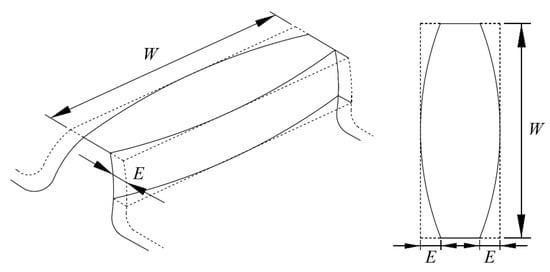
Figure 1.
Illustration of longitudinal crowning.
In this study, the original design of the spur gear set was analyzed first to evaluate its performance. The design parameters in Table 1 are the original design parameters provided by the cooperative manufacturer. Only longitudinal crowning modification was considered in the original design provided by the manufacturer. There were issues of short service life and severe vibrations in the original design. Therefore, tip relief modification and optimization were proposed in this study to reduce the gear contact stress as well as the vibrational levels. The three-dimensional model of the gear set is presented in Figure 2.

Table 1.
Design parameters of spur gear set.
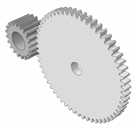
Figure 2.
Three-dimensional model of spur gear pair.
2.2. Unloaded and Loaded Tooth Contact Analysis
Both unloaded tooth contact analysis (TCA) and LTCA were conducted in this study. The STE was calculated through the unloaded TCA []. The gear set exhibited standard involute tooth profiles without tooth modifications. Therefore, the STE of the gear set was zero under an ideal meshing condition. Additionally, to predict the actual meshing performance, the effects of horizontal and vertical axial misalignments, as presented in Figure 3, were also analyzed in TCA.
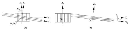
Figure 3.
Illustration of assembly errors: (a) horizontal axial misalignment; (b) vertical axial misalignment.
The LTCA was performed by adopting the commercial finite element package, Abaqus. A mesh generation program for establishing the finite element model of the gear set was developed according to the mathematical model of spur gears and TCA results. A finite element model of a simplified five-tooth pair of the spur gear set and the boundary conditions are depicted in Figure 4. Based on the developed mesh generation codes and the convergence test, element C3D8I was chosen, and the mesh size was set to about 30 μm at the contact area of the gear tooth surface. The nodes were located at the simulated instantaneous contact points from the TCA results of each rotational angle by using the self-developed mesh generation program. Because the contact teeth number is 1~2, a five-tooth model was used instead of the full model for computational efficiency. A torque of 329.35 N-mm was applied to the pinion’s rotational center to make contact with the gear teeth; the base of the gear was fixed. Young’s modulus and Poisson’s ratio of the gear material were 206 GPa and 0.3, respectively.
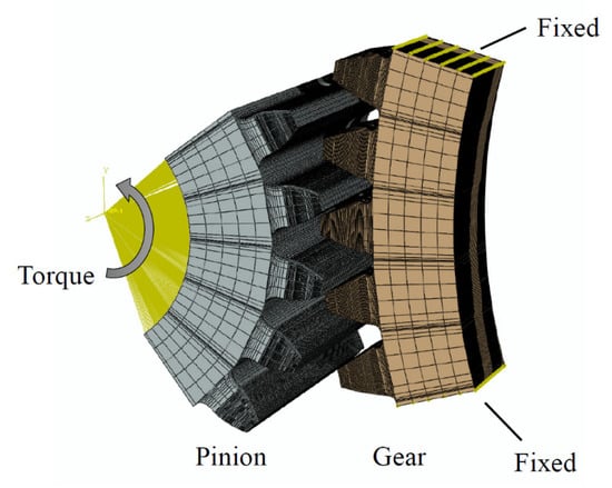
Figure 4.
Boundary condition of finite element analysis.
The unloaded TCA and LTCA enabled us to predict the STE and loaded TE, respectively, as well as the stress distribution on the gear tooth surfaces under ideal meshing conditions and assembly misalignments.
3. Optimization of Gear Tooth Tip Relief Modifications
3.1. Formulation of Optimization and DV
The linear tip relief modification parameters, Ca and La, which denote the amount and length of tip relief modifications, respectively, are depicted in Figure 5. Parameters Ca and La were used as DVs in the following optimization.
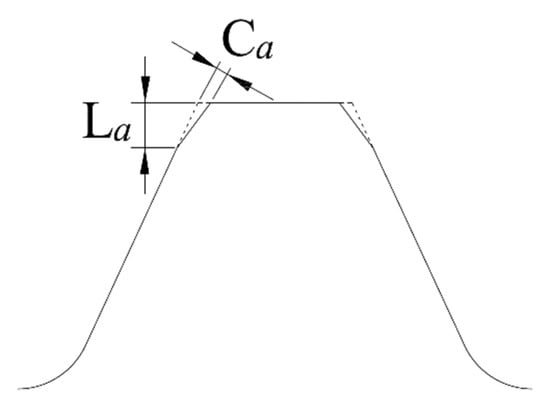
Figure 5.
Illustration of parameters of linear tip relief modification.
For the tip relief parameters in Table 2, we referenced the recommended values by standards such as AGMA 109.6 and ISO 6336 based on the rotational speed and load of the spur gear pair. Then, the lower bounds of Ca and La were set after considering the manufacturing limitation of tip relief by domestic gear manufacturers. Practically, the minimum amount of tip relief modification is 5 μm, and the manufacturing incremental amount of Ca is 1 μm and can only vary between 5 μm and 30 μm. Consequently, a discrete DV optimization algorithm was used for the optimization algorithm because the value of Ca is considered a discrete DV.
Table 2.
DVs of optimization.
The PPLTEs under three assembly conditions, namely ideal condition, horizontal axial misalignment of 0.06°, and vertical axial misalignment of 0.06°, were set as the objective function to be minimized in the optimization. The axial misalignments listed in Table 3 were determined from the designed tolerances and dimensions of bearing bores and shafts provided by the cooperative manufacturer. The worst scenario, i.e., maximum shaft bore clearance and misalignment, was used to determine horizontal and vertical axial misalignments listed in Table 3. The optimization was expected to reveal an optimum set of Ca and La that leads to minimum PPLTE under each of the three assembly conditions. Therefore, a multi-objective optimization formulation was devised on the basis of the DVs and PPLTEs under the three assembly conditions.
Table 3.
PPLTEs of the original design with various assembly conditions.
The multi-objective optimization problem was converted into a single-objective optimization and is expressed as follows:
where fi(x) represents the corresponding PPLTEs under the three assembly conditions, and wi denotes the respective weight. The three weights were equal and set to 1. Parameter fi0 represents the respective PPLTE of the original design under the three assembly conditions (Table 3). The GA in MATLAB computation was used in this study, and the optimization flowchart is presented in Figure 6.
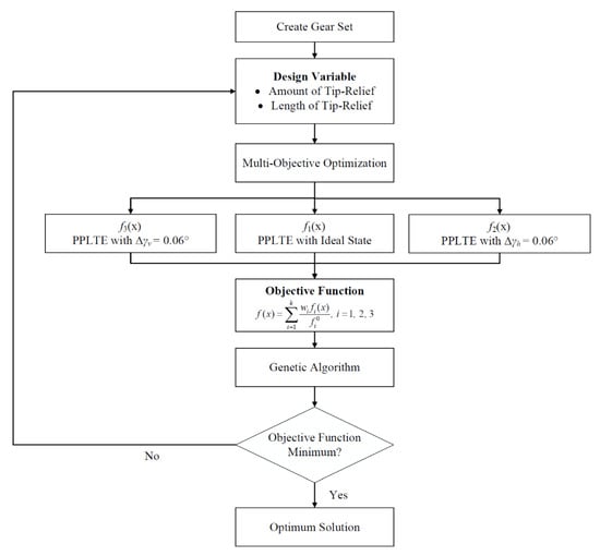
Figure 6.
Optimization analysis flowchart.
3.2. Optimization Results
The optimum DVs of the spur gear set are listed in Table 4. The optimum values of Ca and La were 6 µm and 0.83 mm, respectively. The objective function before and after optimization is listed in Table 5. The PPLTE under the three assembly conditions improved by approximately 73%.
Table 4.
Optimum tip relief modification parameters.
Table 5.
PPLTE improvements in the optimum design. (Unit: µm).
3.3. Contact Stress Analysis of Optimum Design
On the basis of the optimum tip relief modification parameters, the LTCA was performed to predict the gear meshing characteristics. Figure 7a,b presents the contact stress on the pinion and gear; the maximum contact stress of the optimum design under an ideal state was approximately 1029.0 MPa. The gear set exhibited point contact instead of line contact, thus reducing the sensitivity to assembly errors (Figure 7). Therefore, the stress concentration of edge contact caused by misalignment was reduced.
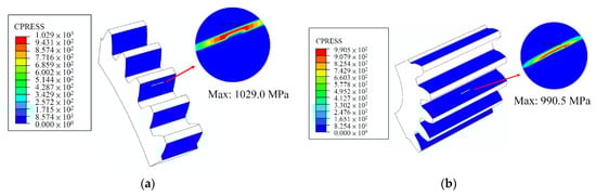
Figure 7.
FEA of optimum design under ideal assembly state: (a) gear; (b) pinion.
In order to predict the actual meshing performance, horizontal and vertical axial misalignments of 0.06° were used in the calculation of PPLTE and finite element analysis (FEA), based on the actual manufacturing tolerances of the gear shaft and bearing bore. The maximum contact stress under a horizontal axial misalignment of 0.06° is 1076.0 MPa. Moreover, the contact stress with a vertical axial misalignment of 0.06° was 986.1 MPa. The results of contact stress from FEA are presented in Figure 8 and Figure 9. Edge contact and stress concentration were successfully avoided under axial misalignments, due to the longitudinal crowning on the gear tooth surfaces. In summary, in addition to reduced PPLTE, the FEA results confirmed that the optimum spur gear set also exhibits acceptable contact stress under the worst scenario of axial misalignments (0.06°) considering manufacturing tolerances.
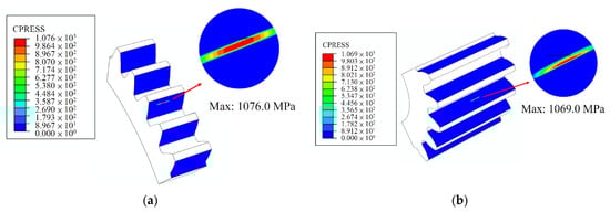
Figure 8.
Contact stress of optimum design with horizontal axial misalignment of 0.06°: (a) gear; (b) pinion.
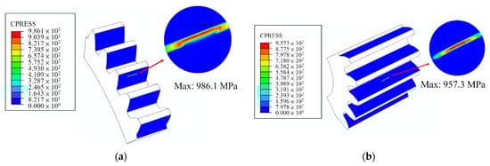
Figure 9.
Contact stress of optimum design under vertical axial misalignment of 0.06°: (a) gear; (b) pinion.
4. Dynamic Analysis
The dynamic characteristics of the spur gear pair with optimum tip relief modification were estimated and analyzed []. The DTEs of the original design and optimum design were simulated according to the established dynamic model of the spur gear pair, STE, and mesh stiffness. Additionally, the acceleration of the spur gear pair under rated load was calculated from the DTE results. The RMS value of acceleration was calculated and used to evaluate the dynamic characteristics of the gear set.
4.1. Dynamic Model
The dynamic model of the spur gear pair (Figure 10) was established with the following assumptions:
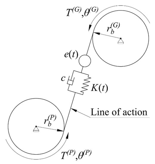
Figure 10.
Dynamic model of spur gear pair.
- The gear meshing process was fully lubricated; thus, the influence of friction was ignored.
- Only the mesh stiffness of the gear pair was considered; the compliances of shafts and bearings were disregarded.
Parameters T(P) and T(G) represent the applied torques on the pinion and gear, respectively; θ(P) and θ(G) denote the respective rotational angles of the pinion and gear; rb(P) and rb(G) represent the radius of the pinion’s and gear’s base circles, respectively (Figure 10). Equivalent stiffness K(t) and equivalent damping c represent the time-varying mesh stiffness and damping of the gear pair along the line of action. The mesh stiffness was estimated from the LTCA results. Value e(t) represents the STE calculated in the TCA.
Let the displacement of the gear system along the line of action be x(t)= rb(P)θ(P) + rb(G)θ(G ) − e(t) during gear meshing, where rb(P)θ(P) + rb(G)θ(G) are the DTEs. Therefore, the dynamic equation of the gear system is as follows:
where meq and F are the equivalent mass and equivalent load of the system, respectively.
4.2. Mesh Stiffness
The mesh stiffnesses of the original design and optimum design were calculated with an ideal state, horizontal axial misalignment, and vertical axial misalignment through LTCA (Figure 11a–c). The mesh process of the spur gear pair contains single tooth contact and double teeth contact, and the mesh stiffness calculation of the two contact states is different. The mesh stiffness K(t) for one tooth contact was calculated by the normal contact force Fn(t) and elastic deformation δe(t) obtained from the FEA, as shown in Equation (3).
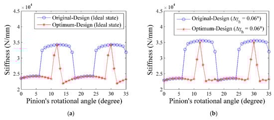
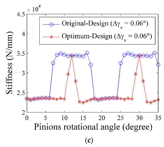
Figure 11.
Mesh stiffness: (a) ideal state; (b) horizontal axial misalignment of 0.06°; (c) vertical axial misalignment of 0.06°.
In addition, the mesh stiffness of double teeth contact Ksys(t) can be calculated by considering the gear contact analogous to two springs in parallel, as shown in Equation (4).
where K1 and K2 represent the respective stiffness of the two contact tooth pairs.
Tip relief modification is essential to avoid tooth tip interference and is accompanied by severe stress concentration caused by tooth deformation during meshing. The two tooth contact region decreases as a consequence of longer linear tip relief. Therefore, there must be a compromise between the two tooth contact region and the amount of tip relief. Optimization was used for solving the compromise and enabled us to determine an adequate set of tip relief parameters, i.e., amount and length of linear tip relief. Although the obtained optimum tip relief parameters exhibited a reduction of the two tooth contact region (Figure 11), the resultant PPLTE was improved and smaller than those of the original design under three assembly conditions by 70% (Table 5). Therefore, the vibration of the optimum design was expected to be reduced since the gear vibration is related to the magnitude of PPLTE.
4.3. DTE and Acceleration
The DTEs of the spur gear set with original and optimum designs under the three assembly conditions were simulated using a dynamic model. The DTE was subsequently differentiated twice to obtain the acceleration signal of the gear system. The RMS values of the acceleration signals of the original design and optimum design were calculated and plotted in Figure 12a–c.
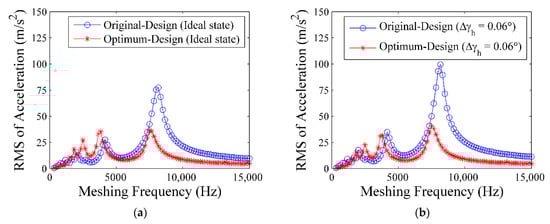
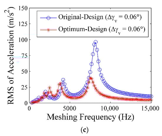
Figure 12.
RMS of acceleration signal: (a) ideal state; (b) horizontal axial misalignment; (c) vertical axial misalignment.
The natural frequencies of the original design and the optimum design were approximately 7500 and 8167 Hz, respectively (Figure 12a–c). This frequency value was affected by the reduction in the double tooth contact area after optimization, in accordance with the mesh stiffness curves illustrated in Figure 11.
The maximum RMS of acceleration of the optimum design, which occurred at the natural frequency, was effectively reduced, compared with that of the original design (Figure 12). The reduced RMS of acceleration implied that the optimum design also exhibited less vibration than the original design under the three assembly conditions. Therefore, the optimum design obtained through static analysis of PPLTE also exhibited high dynamic performance. The percentages of improvement of the optimum design and the improvements under the three assembly conditions ranged from 53% to 60% (Table 6). Therefore, the vibration of the gear system was also successfully minimized through static optimization based on the multi-objective minimization of PPLTEs under the three assembly conditions.
Table 6.
RMS of acceleration at natural frequency. (Unit: m/s2).
5. Dynamic Experiments
5.1. Experimental Framework
Dynamic experiments of the original design and optimum design were performed in accordance with the analyses and optimization detailed in Section 2, Section 3 and Section 4. The parameters of the original design and optimum design spur gear sets are listed in Table 1 and Table 4, and the manufactured optimum design spur gear set is illustrated in Figure 13. We established a high-speed gear dynamic tester for the spur gear dynamic experiments (Figure 14). The high-speed gear tester was composed of a driving servo motor, a driven servo motor for applying loading, and a belt transmission speed increaser with a speed ratio of 3:1 (Figure 14). The maximum rotational speed of the driving motor was 10,000 rpm, and the corresponding speed of the pinion was 30,000 rpm.
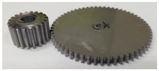
Figure 13.
Manufactured test spur gear set.
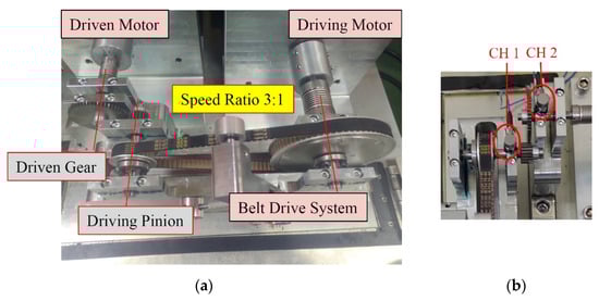
Figure 14.
(a) High speed gear dynamic tester; (b) two accelerometers for acceleration measurement.
One accelerometer was mounted on the bearing seat of the driving shaft and another on the bearing seat of the driven shaft of the dynamic tester (Figure 14b). The experimental acceleration signal at various speeds was transmitted to the computer through the data acquisition system for subsequent signal processing.
For the dynamic experiments, a fixed load (1 N-m) was applied at the driving axis while various rotational speeds (300–30,000 rpm in increments of 300 rpm) were applied at the driving pinion. Both the original design and optimum design spur gear sets were tested on the dynamic tester to measure the vibration behavior.
After acquiring the vibration signals, signal processing was conducted, namely filtering, FFT, and inverse FFT, to reduce noise and attain the desired dynamic characteristics. The RMS values of the filtered acceleration signals at each speed were calculated. The experimental results and simulation results could then be compared with the simulation results.
5.2. Results of Dynamic Tests
The RMS values of acceleration at various speeds from the dynamic test of the original design and optimum designs are depicted in Figure 15. The blue curve and red curve represent the RMS values of acceleration of the original design and the optimum design, respectively. The abscissa axis is the rotational speed of the driving pinion, and the ordinate axis represents the RMS value of the acceleration (Figure 15).
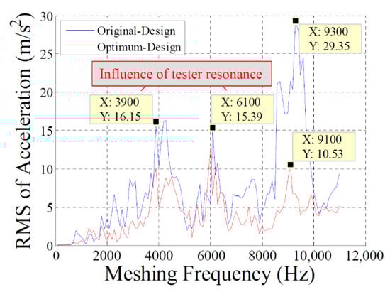
Figure 15.
Experimental RMS of acceleration for original design and optimum design spur gear pairs.
The RMS value near the natural frequency of the gear set was used to evaluate the vibrational level. The overall RMS value of the optimum design (red curve) was less than that of the original design (blue curve; Figure 15). Moreover, the peak value was reduced from 29.35 (at 9300 Hz in the original design) to approximately 10.53 (at 9100 Hz in the optimum design), representing a reduction of 64.1%. The dynamic test revealed that the optimum design spur gear set could also effectively reduce the level of gear vibration; this reduction confirmed the simulation results.
The two curves exhibited substantial fluctuations at a rotational speed of approximately 11,700 rpm and 18,300 rpm—i.e., at gear meshing frequencies of 3900 Hz and 6100 Hz, respectively (Figure 15). The fluctuations presumably were induced by the dynamic tester’s resonance frequency bands, as indicated by the time-frequency diagram in Figure 16.
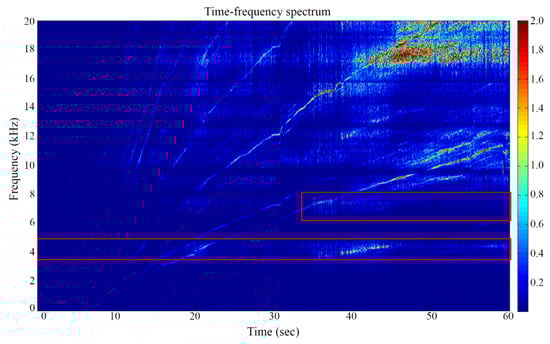
Figure 16.
Time-frequency spectrum of gear dynamic tester.
The time-frequency spectrum of the dynamic tester from the pinion shaft speeds from 600 rpm to 30,000 rpm based on the FFT is illustrated in Figure 16. The higher energy at a fixed frequency occurring in the vicinities of 4000 Hz and 6000 to 7000 Hz indicates the resonance frequency of the dynamic tester (Figure 15). Consequently, the measured gear vibration signals were affected by these resonances of the dynamic tester if the meshing frequency of the gear pair was within the tester’s resonance range (Figure 15).
Experimental results and simulation results of the original design and the optimum design were, respectively, normalized and illustrated for comparison (Figure 17a,b). The following were observed: (1) the overall tendency of the experimental results was consistent with the simulated results, excluding the experimental results influenced by the resonance frequency of the dynamic tester. (2) The simulation results had higher acceleration near the one-half and one-third natural frequencies of the gear pair, which was not apparent in the experiments. Two accelerometers were mounted on the bearing seats of the input and output shafts, respectively, because the high-speed gear pair is too small to accommodate the accelerometers on it (Figure 14). Instead of measuring the torsional vibrations on the gear, the accelerometers acquired vibrational signals passing the shafts, bearings, and bearing seats, containing inevitable noises and decade in the gear vibration signals. As a result, only the peak amplitude at the natural frequency was identified from the experimental dynamic signals. The experimental peak signals at one-half and one-third natural frequencies were hardly identified due to the noises from dynamic tester components and energy loss. (3) In general, the curve of the optimum design was lower than the original design for both the simulation and experiment, which indicated that the optimum design also had a minimized vibrational level.
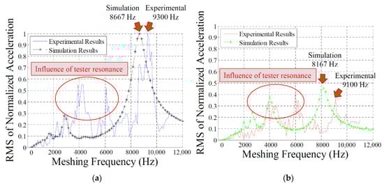
Figure 17.
RMS of normalized acceleration. (a) Original design (b) optimum design.
In sum, the influences of axial misalignments have been explored and analyzed in both static analysis (PPLTE and FEA) and gear dynamics. The results of PPLTE, contact stress, and dynamic performance under assembly errors are shown in Table 5, Figure 8, Figure 9 and Figure 12, respectively. Accordingly, the optimum design can effectively reduce the PPLTE, avoid edge contact under axial misalignments, and lower the RMS of gear acceleration. The gear vibrational experiment verifies that the optimum design possesses a reduced vibrational level than the original design.
6. Conclusions
Gear dynamic simulation and optimization of PPLTE considering actual misalignments are rarely discussed in the literature. In this study, multi-objective optimization was first performed to determine the optimum tip relief modification parameters of a high-speed spur gear pair. The PPLTEs under three assembly conditions were used as the objective functions, and equal weight was applied for converting the multi-objective optimization into a single-objective optimization. The GA from MATLAB computation was selected as the optimization algorithm, and the PPLTEs under the three assembly conditions were successfully reduced by 70%.
Dynamic characteristics of the original design and optimum design spur gear pair were also simulated and compared. A dynamic model of the spur gear system was used to calculate the DTE and simulated acceleration of the gear system. Subsequently, the RMS values of the acceleration at various rotational speeds and meshing frequencies were computed for comparison. According to the dynamic analysis results, the optimum design exhibited a >50% reduction in the peak RMS of acceleration at the natural frequency with an ideal state and horizontal and vertical axial misalignments.
Finally, dynamic experiments were also conducted on our constructed high-speed gear dynamic tester. The experimental results were consistent with those of the simulations. The experimental RMS of acceleration at the natural frequency in the optimum design was lower than that in the original design for both simulation and experiments; this indicates that the optimum design also exhibited an improved vibrational level. In summary, the proposed optimum design spur gear set demonstrated superior static PPLTE and dynamic characteristics compared with the original design, and our design goal was successfully achieved.
Author Contributions
Conceptualization, Z.-G.W., C.-C.L., Y.-C.C. and H.-C.L.; methodology, Z.-G.W., C.-C.L. and H.-C.L.; software, Z.-G.W. and H.-C.L.; validation, Z.-G.W., C.-C.L. and Y.-C.C.; formal analysis, C.-C.L. and H.-C.L.; investigation, Z.-G.W. and H.-C.L.; resources, C.-C.L. and Y.-C.C.; data curation, Z.-G.W. and H.-C.L.; writing—original draft preparation, Z.-G.W., Y.-C.C. and H.-C.L.; writing—review and editing, Z.-G.W., C.-C.L. and Y.-C.C.; visualization, Z.-G.W. and C.-C.L.; supervision, Y.-C.C.; project administration, Y.-C.C.; funding acquisition, Y.-C.C. All authors have read and agreed to the published version of the manuscript.
Funding
This research was funded by the Ministry of Science and Technology (MOST) of Taiwan, grant number MOST-108-2623-E-008-003-D.
Institutional Review Board Statement
Not applicable.
Informed Consent Statement
Not applicable.
Data Availability Statement
Not applicable.
Acknowledgments
The authors would like to thank the National Central University for their academic support in this research.
Conflicts of Interest
The authors declare no conflict of interest.
References
- Smith, J.D. Gear Noise and Vibration, 2nd ed.; Marcel Dekker: New York, NY, USA, 2003. [Google Scholar]
- Litvin, F.L. Theory of Gearing; NASA Reference Publication 1212: Washington, DC, USA, 1989. [Google Scholar]
- Litvin, F.L.; Fuentes, A. Gear Geometry and Applied Theory, 2nd ed.; Cambridge University Press: New York, NY, USA, 2004. [Google Scholar]
- Chang, S.L.; Tsay, C.B.; Tseng, C.H. Kinematic optimization of a modified helical gear train. J. Mech. Des. 1997, 119, 307–314. [Google Scholar] [CrossRef]
- Chen, Y.C.; Tsay, C.B. Stress analysis of a helical gear set with localized bearing contact. Finite Elem. Anal. Des. 2002, 38, 707–723. [Google Scholar] [CrossRef]
- Bonori, G.; Barbieri, M.; Pellicano, F. Optimum profile modifications of spur gears by means of genetic algorithms. J. Sound Vib. 2008, 313, 603–616. [Google Scholar] [CrossRef]
- Faggioni, M.; Samani, F.S.; Bertacchi, G.; Pellicano, F. Dynamic optimization of spur gears. Mech. Mach. Theory 2011, 46, 544–557. [Google Scholar] [CrossRef]
- Ogawa, Y.; Matsumura, S.; Houjoh, H.; Sato, T. Rotational vibration of a spur gear pair having tooth helix deviation: Effect of lead modifications. In Proceedings of the 2003 ASME Design Engineering Technical Conferences and Computers and Information in Engineering Conference, Chicago, IL, USA, 2–6 September 2003; pp. 433–440. [Google Scholar]
- Houjoh, H.; Ratanasumawong, C.; Matsumura, S. Utilization of synchronous averaging for inspection of tooth surface undulations on gears (Localization of nonmesh harmonic components to individual gear). J. Appl. Mech. 2007, 74, 269–278. [Google Scholar] [CrossRef]
- Ratanasumawong, C.; Matsumura, S.; Houjoh, H. An alternative method for evaluating gear tooth surface geometry based on synchronous average of vibration of a gear pair. In Proceedings of the 2007 ASME Design Engineering Technical Conferences and Computers and Information in Engineering Conference, Las Vegas, NV, USA, 4–7 September 2007; pp. 395–403. [Google Scholar]
- Ratanasumawong, C.; Matsumura, S.; Tatsuno, T.; Houjoh, H. Estimating gear tooth surface geometry by means of the vibration measurement: Distinction of the vibration characteristics of gears with tooth surface form error. J. Mech. Des. 2009, 131, 101003. [Google Scholar] [CrossRef]
- Kahraman, A.; Singh, R. Non-linear dynamics of a spur gear pair. J. Sound Vib. 1990, 142, 49–75. [Google Scholar] [CrossRef]
- Kahraman, A.; Singh, R. Non-linear dynamics of a geared rotor-bearing system with multiple clearances. J. Sound Vib. 1991, 144, 469–506. [Google Scholar] [CrossRef]
- Kahraman, A.; Singh, R. Interactions between time-varying mesh stiffness and clearance non-linearities in a geared system. J. Sound Vib. 1991, 146, 135–156. [Google Scholar] [CrossRef]
- Kahraman, A.; Blankenship, G.W. Experiments on nonlinear dynamic behavior of an oscillator with clearance and periodically time-varying parameters. J. Appl. Mech. 1997, 64, 217–226. [Google Scholar] [CrossRef]
- Kahraman, A.; Blankenship, G.W. Effect of involute tip relief on dynamic response of spur gear pairs. J. Mech. Des. 1999, 121, 313–315. [Google Scholar] [CrossRef]
- Hotait, M.; Kahraman, A. Experiments on the relationship between the dynamic transmission error and the dynamic stress factor of spur gear pairs. Mech. Mach. Theory 2013, 70, 116–128. [Google Scholar] [CrossRef]
- Inalpolat, M.; Handschuh, M.; Kahraman, A. Influence of indexing errors on dynamic response of spur gear pairs. Mech. Syst. Signal Process. 2015, 60, 391–405. [Google Scholar] [CrossRef]
- Anichowski, B.J.; Kahraman, A.; Talbot, D. Dynamic transmission error measurements from spur gear pairs having tooth indexing errors. In Proceedings of the International Design Engineering Technical Conferences and Computers and Information in Engineering Conference, Cleveland, OH, USA, 6–9 August 2017; pp. 1–8. [Google Scholar]
- Wang, Z.G.; Chen, Y.C. Design of a helical gear set with adequate linear tip-relief leading to improved static and dynamic characteristics. Mech. Mach. Theory 2020, 147, 103742. [Google Scholar] [CrossRef]
Publisher’s Note: MDPI stays neutral with regard to jurisdictional claims in published maps and institutional affiliations. |
© 2022 by the authors. Licensee MDPI, Basel, Switzerland. This article is an open access article distributed under the terms and conditions of the Creative Commons Attribution (CC BY) license (https://creativecommons.org/licenses/by/4.0/).