Article

Neural Network Based Adaptive Event-Triggered Control for Quadrotor Unmanned Aircraft Robotics

1
School of Automation Engineering, Northeast Electric Power University, Jilin 132012, China
2
Jilin Provincial International Joint Research Center of Precision Drive and Intelligent Control, Northeast Electric Power University, Jilin 132012, China
3
State Key Laboratory of Synthetical Automation for Process Industries, Northeastern University, Shenyang 110819, China
4
Department of Mechanical and Industrial Engineering, Concordia University, Montreal, QC H3B 1R6, Canada
*
Authors to whom correspondence should be addressed.
Machines 2022, 10(8), 617; https://doi.org/10.3390/machines10080617
Submission received: 22 June 2022 / Revised: 22 July 2022 / Accepted: 23 July 2022 / Published: 27 July 2022
(This article belongs to the Special Issue Intelligent Mechatronics, Automation, Control Systems)

Abstract

:
With the aim of addressing the problem of the trajectory tracking control of quadrotor unmanned aircraft robots (UARs), in this study, we developed a neural network and event-triggering mechanism-based adaptive control scheme for a quadrotor UAR control system. The main technologies included this scheme are as follows. (1) Under the condition that only the quadrotor’s position information can be obtained, a modified high-gain state observer-based adaptive dynamic surface control (DSC) method was applied and the tracking control of quadrotor UARs was acquired. (2) An event-triggered mechanism for UARs was designed, in which the energy consumption was greatly reduced and the communication efficiency between the system and the control terminal was improved. (3) By selecting appropriate parameters, appropriate initial conditions for the adaptive laws, and establishing a high-gain state observer, a tracking performance of L could be achieved. Finally, simulation results of the hardware-in-loop strategy are presented. The control method we propose here outperformed the traditional backstepping sliding mode control (BSMC) scheme.

1. Introduction

The problem of controlling quadrotor systems has recently attracted significant attention. It has been commonly applied in the fields of rescue missions and agricultural service; however, a problem continues to disrupt the control of quadrotor systems [1,2,3,4]. Because of factors including measurement errors, quadrotor unmanned aircraft robots (UARs) are modeled as complex nonlinear systems, which increases the difficulty involved in controlling these systems [5,6,7,8]. Therefore, the question of how to choose a reasonable and effective adaptive algorithm for the accurate control of quadrotor UARs has become an urgent problem.
In practical applications, external disturbances are always ignored in the process of controller design, which results in lower system robustness. Thus, the design of the controller is the key to obtaining a good performance in trajectory tracking under the influence of external disturbances. In [9,10], a proportional-integral-derivative (PID) controller provided active interference suppression by combining active disturbance rejection technology with the PID control method to ensure the rapid observation of errors. In [11], the uncertainty and the model’s measurement noise were generated by means of a neural network approximator. A robust compensator was proposed to eliminate any approximation errors and achieve effective high-precision trajectory tracking control. In [12,13,14,15], to improve the control precision of a quadrotor system, an algorithm based on the BSMC approachwas proposed, which overcame the nonlinear effects of the quadrotor.
However, another problem remains, in that a “differential explosion” can occur when the design of the controller steps relies on the BSMC control scheme.To deal with the differential explosion problems, refs. [16,17] combined the extended state observer and the dynamic surface schemes to propose a control method for quadrotor trajectory tracking, which ensured the stability of the control system and effectively solved the differential explosion problem. In [18], a dynamic model of quadrotor flight height was established. Ref. [18] achieved this by comparing the traditional first-order SMC algorithm with the second-order SMC algorithm to obtain a new quadrotor height control algorithm. However, the proposals introduced thus far involve strong assumptions and require all states of the quadrotor to be available.
In addition, the process of signal transmission also has an important role in the quadcopter control system. In [19], to cope with the high-pressure problem of constant signal transmissions from the quadcopter and the console, a control scheme based on a fixed-time-triggered mechanism was introduced into the steps of controller design, which relieved the communication pressure by using periodic transmissions to update the control signals. However, when the control performance is unsatisfactory, a method used to improve the control performance is to reduce the sampling period. At present, if the control signal is still updated at the previous frequency, this inevitably leads to unwanted resource waves [20]. In [21,22], control schemes based on an event-triggered mechanism were applied to cope with the fixed-time triggering approach, which showed good performance.
The previous trigger moment influences the event-triggered mechanism and determines the next trigger moment. At the time of triggering, the console and the quadrotor do not need to communicate; therefore, the communication pressure of the quadrotor can be decreased. However, the event triggering mechanism may suffer from Zeno behavior, in which the trigger event can be triggered numerous times in a narrow timeframe [23,24,25]. In relation to this issue, the basic properties of the minimum event-triggered intervals in event-triggered mechanisms were studied in [26]. In [27,28,29,30], the event-triggered mechanism was introduced into the design of the controller, which greatly reduced the transmission pressure of the control signal. Therefore, a feasible method involves adding an event-triggered mechanism into the process of controller design for quadrotors in order to decrease the pressure of quadrotor communication. The application of event triggering mechanisms has been examined in several studies with respect to the controller design process for quadrotor UARs. However, the authors mentioned above, such as [22], have not considered the problem of quadrotor position tracking control when a quadrotor UAR can only measure its position in relation to certain pieces of information.
In summary, many algorithms have been developed to solve control problems related to quadrotor UARs. However, according to our recent search results, coping with the control problems of quadrotor UARs remains a challenging issue. To solve these problems, based on [12,13,20,31], a neural network and event-triggering-mechanism-based adaptive control method for a quadrotor UAR control system is proposed in this paper. An unknown air drag coefficient, aerodynamic drag coefficient, and rotational inertia are approximated by means of a neural network. The trajectory tracking control of a quadrotor UAR’s positioning is achieved by means of the DSC technique and a controller design involving state feedback. The trajectory tracking control of a quadrotor UAR’s attitudeis addressed by means of an output feedback controller. The main innovations of this paper are:
(1)
To our best knowledge, for the first time we present an adaptive DSC scheme with a modified high-gain observer that has been designed for quadrotor UARs under the condition that only the position data of the quadrotor system are available, along with the testing of the quadrotor UAR controller in the hardware-in-loop simulation platform. Thus, the underactuation problem in quadrotor UARs is perfectly solved, and precise tracking performance is obtained.
(2)
By designing an event triggering mechanism for quadrotor UARs, the control signal can be updated immediately when threshold conditions are triggered. Therefore, compared with the time-triggered control mechanism, the energy consumption can be greatly reduced, and the communication pressure between the system and the control terminal is lowered using the event triggering mechanism.
(3)
By setting the original conditions of the high-gain state observer, adaptive control laws, and the appropriate controller parameters, a tracking performance of L for underactuated quadrotor UARs is achieved.

2. Problem Statement

2.1. Model Construction

The quadrotor body coordinate system and ground coordinate system are shown in Figure 1, wherein the quadrotor has a total of six degrees of freedom in the output, with translational degrees of freedom in three directions and rotational degrees of freedom in three directions. Moreover, the thrust of the UARs is produced by four motors, which located at the corners of the quadrotor body. Among these, F 2 and F 4 are driven by two positive propeller motors, and F 1 and F 3 are driven by two anti-positive propeller motors. However, this structure leads to the need for the balancing of yaw torque as required. For example, under the condition in which the lift force is greater than the quadrotor’s mass, the quadrotor will rise vertically when increasing the output power of the four motors at the same time. Moreover, if F 2 > F 4 , F 1 = F 3 , a pitching motion will be observed and the machine will exhibit translational motion along the y-axis. Hence, by adjusting the speed of the motors, attitude control and position control of the UAR can be attained.
Faced with the control problem of quadrotor UARs, here the rigid body transdynamics, as well as the Newton–Euler equations are used to model the quadrotor. We have [ ϕ , θ , ψ ] R 3 and [ p , q , r ] R 3 , with ϕ , θ , ψ designating the roll, pitch and yaw angles with regard to the ground coordinates, which are represented by O x e y e z e , and p , q , r are the angular speed the of roll, pitch, and yaw movements with respect to the body coordinates, which are denoted by O x b y b z b . An explanation of the other symbols is given in Table 1. To clarify the connections among the inertial coordinate system and the body coordinate system, we use conversion equations. Choosing the x-axis as an example [32]
X = x , Y = cos ϕ y sin ϕ z , Z = sin ϕ y + cos ϕ z ,
where X , Y , Z are the inertial coordinate system and x , y , z are the quadrotor body coordinate system. The transformation matrix can be expressed as
R ( x , ϕ ) = 1 0 0 0 cos ϕ sin ϕ 0 sin ϕ cos ϕ
The rotation matrix of the Y axis and the Z axis can be obtained as follows:
R ( y , θ ) = cos θ 0 sin θ 0 1 0 sin θ 0 cos θ
R ( z , ψ ) = cos ψ sin ψ 0 sin ψ cos ψ 0 0 0 1
Then the overall conversion relationship between the inertial coordinate system and the body coordinate system is:
R ( ϕ , θ , ψ ) = cos θ cos ψ A C cos θ sin ψ B D sin θ cos θ sin ϕ cos ϕ cos θ
with A = cos ψ sin ϕ sin θ cos ϕ sin ψ , B = cos ϕ cos ψ + sin ϕ sin θ sin ψ , C = sin ϕ sin ψ + sin ϕ cos ψ sin θ , D = cos ϕ sin θ s i n ψ c o s ψ s i n ϕ . F E = F 1 + F 2 + F 3 + F 4 . Then, the motion model, as well as the angular motion of the quadrotor with respect to the ground coordinate system, can be expressed as:
X ¨ = F E sin ϕ sin ψ + cos ϕ cos ψ s i n θ K X X ˙ / m + d X ( t ) Y ¨ = F E cos ψ sin θ sin ψ cos ψ s i n ϕ K Y Y ˙ / m + d Y ( t ) Z ¨ = F E cos ϕ cos θ K Z Z ˙ m g / m + d Z ( t ) ϕ ¨ = θ ˙ ψ ˙ I y I z I r θ ˙ ω ¯ d ϕ ϕ ˙ + l F 4 F 2 / I x + d 1 ( t ) θ ¨ = ϕ ˙ ψ ˙ I z I x I r θ ˙ ω ¯ d θ θ ˙ + l F 3 F 1 / I y + d 2 ( t ) ψ ¨ = ϕ ˙ θ ˙ I x I y d ψ ψ ˙ + τ 2 + τ 4 τ 1 τ 3 / I z + d 3 ( t )
with ω ¯ = ω 2 + ω 4 ω 1 ω 3 . We can determine that x X , 1 = X , x X , 2 = X ˙ ,   x Y , 1 = Y , x Y , 2 = Y ˙ , x Z , 1 = Z , x Z , 2 = Z ˙ ,   x 1 = ϕ , x 2 = ϕ ˙ , x 3 = θ , x 4 = θ ˙ , x 5 = ψ , x 6 = ψ ˙ . Then, Equation (6) can be rewritten as follows
x ˙ X , 1 = x X , 2 , x ˙ X , 2 = ( cos x 1 sin x 3 cos x 5 + sin x 1 sin x 5 ) U 4 a 1 x X , 2 + d X t , x ˙ Y , 1 = x Y , 2 , x ˙ Y , 2 = ( cos x 1 sin x 3 sin x 5 sin x 1 cos x 5 ) U 4 a 2 x Y , 2 + d Y t , x ˙ Z , 1 = x Z , 2 , x ˙ Z , 2 = cos x 1 cos x 3 U 4 a 3 x Z , 2 + d Z t g , y i = x i , 1 , i = X , Y , Z , x ˙ 1 = x 2 , x ˙ 2 = a 4 x 4 x 6 + a 5 ω ¯ x 4 a 6 x 2 + U 1 + d 1 t , x ˙ 3 = x 4 , x ˙ 4 = a 7 x 2 x 6 + a 8 ω ¯ x 2 a 9 x 4 + U 2 + d 2 t , x ˙ 5 = x 6 , x ˙ 6 = a 10 x 2 x 4 a 11 x 6 + U 3 + d 3 t , y j = x 2 j 1 , j = 1 , 2 , 3 ,
with a 1 = K X / m , a 2 = K Y / m , a 3 = K Z / m , a 4 = I y I z / I x , a 5 = I r / I x , a 6 = d ϕ / I x ,   a 7 = I z I x / I y , a 8 = I r / I y ,   a 9 = d θ / I y , a 10 = I x I y / I z ,   a 11 = d ψ / I z are unknown; U 1 , U 2 , U 3 and U 4 are the control inputs, wherein U 1 = l ( F 4 F 2 ) / I x , U 2 = l ( F 3 F 1 ) / I y , U 3 = τ 2 + τ 4 τ 1 τ 3 / I z , U 4 = ( F 1 + F 2 + F 3 + F 4 ) / m .
Remark 1.
It should be noted that the bounded external disturbances d X ( t ) , d Y ( t ) , d Z ( t ) , d 1 ( t ) , d 2 ( t ) , and d 3 ( t ) considered in this paper could denote the force of the wind, wind gusts, noise, electromagnetism, and bad weather while the quadrotor system is working.

2.2. Radial Basis Function Neural Networks (RBFNNs)

In this work, under Lemma 1, any continuous function on the compact sets can be approximated by applying the RBFNNs.
Lemma 1
(see [33]). With f i ξ i : Ω ξ i R , i = X , Y , Z , are smooth and Ω ξ i R q being compact sets, ξ i represents the RBFNN’s input, and q is the input dimension for any ε m > 0 , by properly selecting η i and ξ k R q , k = 1 , , N , then, for some sufficiently large integer N , an RBFNN is factored in and expressed as:
f i ξ i = ψ i T ξ i ϑ i * + ε i , i = X , Y , Z ξ i Ω ξ i R q , ε i ε m
where Y i ξ i is the output of the RBFNN, and ϑ i * denotes the optimal weight vector of ϑ i and is expressed as ϑ i * = arg min ϑ i R N sup ξ i Ω ξ i Y i ξ i f i ξ i ,   ψ k ξ = exp ξ ξ k 2 η 2 . This is the basis function, where η > 0 serves as the width of the basis function and ξ k R q is the center of the basis function, which serves as a constant vector, with ε i representing the approximated errors, with ε i = f i ξ i ϑ i * T ψ i ξ i .
For proof, let
U X = ( cos x 1 sin x 3 cos x 5 + sin x 1 sin x 5 ) U 4 U Y = ( cos x 1 sin x 3 sin x 5 sin x 1 cos x 5 ) U 4 U Z = cos x 1 cos x 3 U 4 ,
and f X x = a 1 x X , 2 , f Y x = a 2 x Y , 2 , f Z x = a 3 x Z , 2 . Therefore, (7) can be expressed as
x ˙ X , 1 = x X , 2 , x ˙ X , 2 = U X + f X x + d X t , x ˙ Y , 1 = x Y , 2 , x ˙ Y , 2 = U Y + f Y x + d Y t , x ˙ Z , 1 = x Z , 2 , x ˙ Z , 2 = U Z + f Z x + d Z t g , y i = x i , 1 , i = X , Y , Z , x ˙ 1 = x 2 , x ˙ 2 = a 4 x 4 x 6 + a 5 ω ¯ x 4 a 6 x Z , 2 + U 1 + d 1 t , x ˙ 3 = x 4 , x ˙ 4 = a 7 x 2 x 6 + a 8 ω ¯ x 2 a 9 x 4 + U 2 + d 2 t , x ˙ 5 = x 6 , x ˙ 6 = a 10 x 2 x 4 a 11 x 6 + U 3 + d 3 t , y j = x 2 j 1 , j = 1 , 2 , 3 .
Note that the air drag coefficients are K X , K Y , K Z , whereas the continuous functions represented by system parameters a 1 , a 2 , and   a 3 are also unknown. Thus, the above proof can be approximated by means of RBFNNs in Lemma 1.
To define x 5 r , it is important to define the desired trajectories of the yaw angle. The next step is to realize the control scheme. To achieve this, the following assumptions are required [34]:
A1:
The reference trajectories are y r i , i = X , Y , Z , and x 5 r are the smooth and bounded functions, [ y r i , y ˙ r i , y ¨ r i ] T , which are part of a set of known compact, Ω r when t > 0 .
A2:
The external disturbances can be represented as d i ( t ) d ¯ i , wherein d ¯ i are positive constants, i = 1 , 2 , 3 , X , Y , Z .
A3:
The angles of roll and pitch are limited to ( π / 2 , π / 2 ) in accordance with the physical meaning. In particular, the yaw angle range of ( π / 2 , π / 2 ) was selected for the purposes of this study.

3. Proposed Methodology

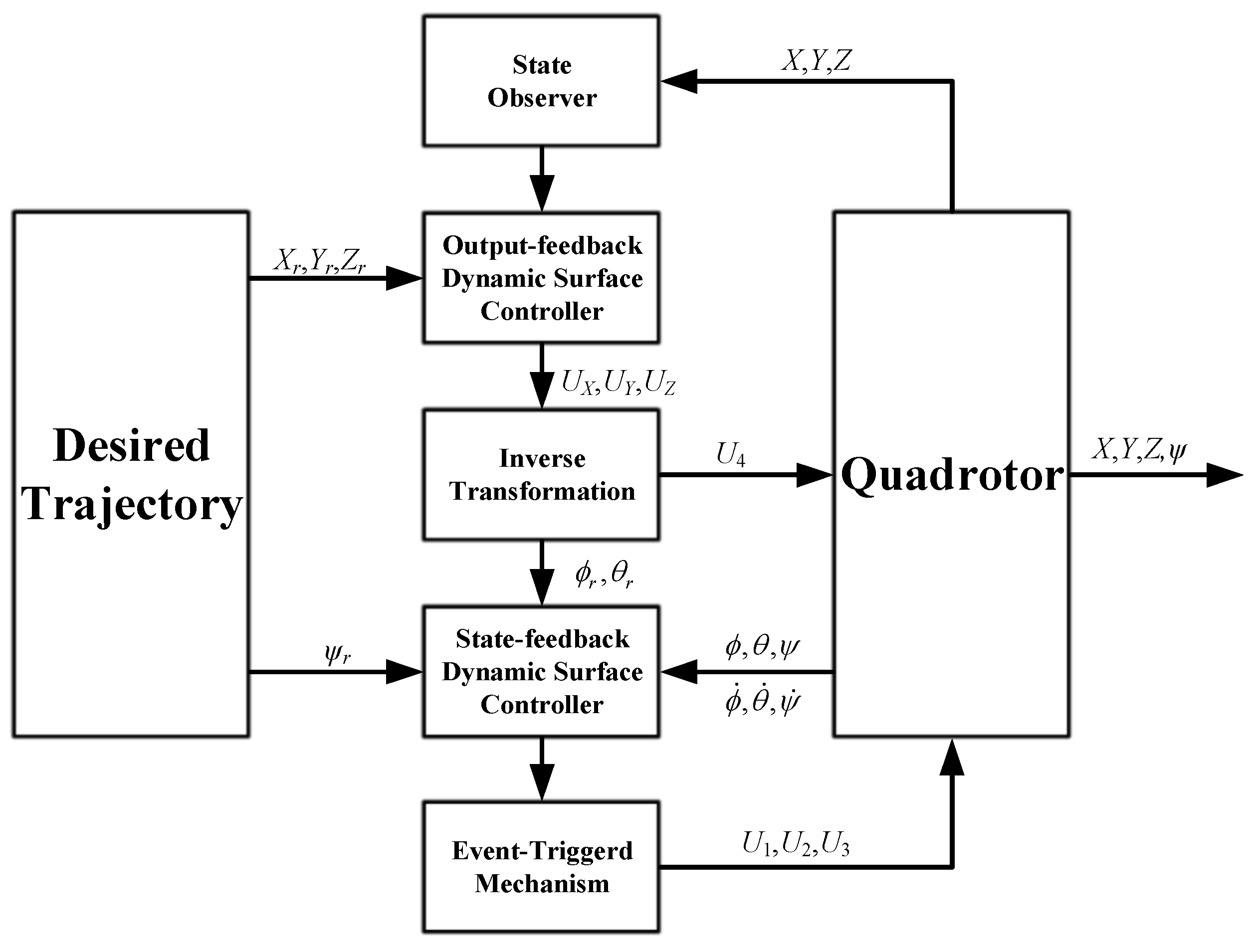
In this paper, we present a neural network and event-triggered-mechanism-based adaptive control method. The architecture of the control method is presented in Figure 2. The output-feedback controller is designed to achieve the position model part from the quadrotor. The part of the model related to the attitude of the quadrotor can be realized using the state-feedback method.

3.1. Controller Design for Positioning Trajectory Tracking

The position model of the quadrotor is expressed as follows:
x ˙ i = A i x i + Ψ i T ξ i ϑ i * + ε i + D i b t + G i + b i U i y i = x i , 1
with A i = 0 1 0 0 , ϑ i * = 0 ϑ i , 2 * , b i = 0 1 , Ψ i T = 0 0 0 ψ i , 2 , ε i = 0 ε i , 2 , G X = G Y = 0 0 , G Z = 0 g , D i b t = 0 d i t , i = X , Y , Z . Let B i = ε i + D i b t + G i , and A i , 0 = A i q i e i , 1 T = q i , 1 1 q i , 2 0 , where q i = q i , 1 q i , 2 , and A i , 0 denotes a Hurwitz matrix determined by selecting the proper vector q i . It follows that
x ˙ i = A i , 0 x i + q i y i + Ψ i T ξ i ϑ i * + B i + b i U i , 0 y i = e 1 T x i , i = X , Y , Z .
Inspired by [4,35,36,37] the high-gain K-filter observer is used to estimate the unmeasured states, and the K-filter observer is designed by:
v ˙ i , 0 = k i A i , 0 v i , 0 + Δ i 1 e i , 2 U i , 0 ς ˙ i , 0 = k i A i , 0 ς i , 0 + k i q i y i Ξ ˙ i = k i A i , 0 Ξ i + Δ i 1 Ψ i T ,
where i = X , Y , Z , k i 1 denote the positive design parameters, and e i , 2 is the second coordinate vector in R 2 with
Δ i = d i a g 1 , k i .
From (13) and (14), the estimated state vector is used as follows:
x ^ i = Δ i ς i , 0 + Δ i v i , 0 + Δ i Ξ i ϑ i * .
Then, for the estimation error we can obtain:
ϵ i = x i x ^ i ,
with:
ϵ ˙ i = x ˙ i x ^ ˙ i = A i ϵ i k i Δ i q i ϵ i , 1 + B i
where ϵ i , 1 is the first entries of ϵ i . Since ϑ i * is unknown, the actual states can be estimated with the estimated value ϑ ^ i of ϑ i * , and it follows that:
x ^ ^ i = Δ i ς i , 0 + Δ i v i , 0 + Δ i Ξ i ϑ ^ i .
Lemma 2.
The quadratic function can be described by:
V ϵ i : = ϵ i T P i ϵ i
with P i = Δ i 1 T P ¯ i Δ i 1 , wherein P ¯ i = P ¯ i T > 0 is a positive definite metrix, which satisfies
A i , 0 T P ¯ i + P ¯ i T A i , 0 = 2 I ,
For k i 1 , it follows that:
V ˙ ϵ i k i λ max P ¯ i V ϵ i + k i ( P ¯ i B i max k i 2 ) 2 .
Proof. 
Please see the proof of Lemma 2 in Appendix A. □

Design of Controller with Dynamic Surface Control Method

Step 1: The error from the first surface can be expressed as
S i , 1 = y i y r i .
Then, S ˙ i , 1 is defined as
S ˙ i , 1 = y ˙ i y ˙ r i = x i , 2 y ˙ r i .
From (16), we have:
x i , 2 = x ^ i , 2 + ϵ i , 2 = k i ς i , ( 0 , 2 ) + k i v i , ( 0 , 2 ) + k i Ξ i , ( 2 ) ϑ i * + ϵ i , 2
where Ξ i , ( 2 ) denotes the second row of Ξ i . Furthermore, we have
S ˙ i , 1 = k i ς i , ( 0 , 2 ) + k i v i , ( 0 , 2 ) + k i Ξ i , ( 2 ) ϑ i * + ϵ i , 2 y ˙ r i = k i ς i , ( 0 , 2 ) + k i v i , ( 0 , 2 ) v ¯ i , ( 0 , 2 ) + k i v ¯ i , ( 0 , 2 ) + k i Ξ i , ( 2 ) ϑ i * + ϵ i , 2 y ˙ r i
where v ¯ i , ( 0 , 2 ) denote the signals of virtual control. It follows that
v ¯ i , ( 0 , 2 ) = l i , 1 S i , 1 k i ς i , ( 0 , 2 ) ϑ ^ i T k i Ξ i , ( 2 ) T + y ˙ r i / k
where l i , 1 are design constants and ϑ ^ i is the estimated values of ϑ i * .
ϑ ^ i denotes the update law, which is expressed as
ϑ ^ ˙ i = γ ϑ i k i Ξ i , ( 2 ) T S i , 1 σ ϑ i ϑ ^ i .
Let v ¯ i , ( 0 , 2 ) be expressed as the first-order low-pass filter input; it follows that:
z i , 2 + τ i , 2 z ˙ i , 2 = v ¯ i , ( 0 , 2 ) , z i , 2 0 = v ¯ i , ( 0 , 2 ) 0
Step 2: Let S i , 2 be expressed as
S i , 2 = v i , ( 0 , 2 ) z i , 2 .
Then, S ˙ i , 2 is defined as
S ˙ i , 2 = k i q i , 2 v i , ( 0 , 1 ) + k i 1 U i , 0 z ˙ i , 2 .
The final control law is obtained as
U i , 0 = k i k i q i , 2 v i , ( 0 , 1 ) l i , 2 S i , 2 + z ˙ i , n .
Then, the event-triggered-mechanism-based adaptive controller can be expressed as
U ˘ i ( t ) = U i , 0 g i , 1 tanh k 1 S i , 2 g i , 1 ρ i ,
The trigger events are expressed as:
U i t = U ˘ i t n , t t n , t n + 1 , t n + 1 = inf t > t n | e i t g i ,
where t n , n Z + , ρ i > 0 , g i , 1 > g i denote the designed parameters, which are positive, and e i t = U ˘ i ( t ) U i t represent the errors of measurement. When the trigger events occur, then the control signals U i t are updated to U ˘ i t n + 1 and the control signals U i t = U ˘ i t n are satisfied when t t n , t n + 1 .
According to (9), it can be seen that U X , U Y , U Z denote the designed control signals. However, there are four variables in (9), which are given as x 1 , x 3 , x 5 and U 4 , respectively. These four unknown variables must be calculated. However, it is commonly known that the above unknown variables can not be solved by means of three equations. For this reason, an extra signal must be provided in the control scheme. In this paper, the yaw angle, which is represented by x 5 r , is given and the designed control signal U 3 guarantees that the state x 5 will converge to the reference x 5 r . Then, reference signals x 1 r , x 3 r of x 1 , x 3 and U 4 can be obtained by solving Equation (9) as follows: x 3 r = arctan ( ( U X cos x 5 r + U Y sin x 5 r ) / U Z ) , x 1 r = arctan ( ( U X sin x 5 r U Y cos x 5 r ) cos x 3 r / U Z ) , U 4 = U Z / cos x 1 r cos x 3 r .

3.2. Controller Design of Attitude Trajectory Tracking

The mathematical model of the quadrotor’s attitude can be rewritten as:
x ˙ 2 j 1 = x 2 j x ˙ 2 j = Θ α j T Γ α j + U j , 0 + d j t y j = x 2 j 1
where j = 1 , 2 , 3 , Θ α 1 = a 4 , a 5 , a 6 T , Θ α 2 = a 7 , a 8 , a 9 T , Θ α 3 = a 10 , a 11 T , Γ α 1 = x 4 x 6 , ϖ x 4 , x 2 T , Γ α 2 = x 2 x 6 , ϖ x 2 , x 4 T , Γ α 3 = x 2 x 4 , x 6 T .
Step 1: Define the error of the first surface as:
S 2 j 1 = x 2 j 1 x 2 j 1 r .
For analysis, let Lyapunov functions be defined as:
V 2 j 1 = 1 2 S 2 j 1 2 .
Then, the time derivatives of V ˙ 2 j 1 yield
V ˙ 2 j 1 = S 2 j 1 S ˙ 2 j 1 = S 2 j 1 x 2 j x 2 j d + S 2 j 1 x 2 j d S 2 j 1 x ˙ 2 j 1 r .
Based on the virtual control law x 2 j d , it follows that:
x 2 j d = k 2 j 1 S 2 j 1 + x ˙ 2 j 1 r .
We define z 2 j , which can be acquiredby a first-order low-pass filter. It follows that
z 2 j + ι 2 j z ˙ 2 j = x 2 j d , z 2 j 0 = x 2 j d 0
where x 2 j d and ι 2 j represent the input as well as the positive time constants of the first-order low-pass filter, respectively. We have
V ˙ 2 j 1 = S 2 j 1 ( S 2 j k 2 j 1 S 2 j 1 ) + S 2 j 1 y 2 j .
Step 2: Define S 2 j as
S 2 j = x 2 j z 2 j .
Then, the time derivatives of S 2 j yield
S ˙ 2 j = x ˙ 2 j z ˙ 2 j = Θ α j T Γ α j + U j , 0 + d j t z ˙ 2 j .
Define the following Lyapunov functions as:
V 2 j = 1 2 S 2 j 2 + 1 2 r Θ α j Θ ˜ α j 2 .
Then, we have:
V ˙ 2 j = S 2 j S ˙ 2 j + 1 r Θ α j Θ ˜ α j T Θ ^ ˙ α j = S 2 j ( Θ α j T Γ α j + U j , 0 + d j t z ˙ 2 j ) + 1 r Θ α j Θ ˜ α j T Θ ^ ˙ α j .
Therein, the final control law can be obtained as follows:
U j , 0 = k 2 j S 2 j S 2 j Θ ^ α j T Γ α j + z ˙ 2 j
where ϑ ^ α j are updated by:
Θ ^ ˙ α j = r Θ α j Γ α j S 2 j σ Θ α j Θ ^ α j .
Then, the event-triggering-mechanism-based adaptive controller can be expressed as
U ˘ j ( t ) = ( 1 + δ j ) U j , 0 ψ ¯ j tanh S 2 ψ ¯ j β j ,
and the trigger events are designed as follows:
U j t = U ˘ j t k , t t k , t k + 1 , t k + 1 = inf t > t k | e j t δ j U j ( t ) + ψ j ,
where t k , k Z + , β j > 0 , 0 < δ j < 1 , ψ j > 0 , ψ ¯ j ψ j / ( 1 δ j ) are the positive design parameters and e j t = U ˘ j ( t ) U j t are the errors of measurement.

3.3. L Performance and the Stability of the Control Scheme

Let the errors from the output and input of the first-order low-pass filters be expressed as
y i , 2 = z i , 2 v ¯ i , ( 0 , 2 ) , i = X , Y , Z , y 2 j = z 2 j x ( 2 j ) d , j = 1 , 2 , 3 .
One has
y ˙ i , 2 = y i , 2 τ i , 2 + l i , 1 S ˙ i , 1 + k i ς ˙ i , ( 0 , 2 ) + k i ϑ ^ ˙ i Ξ i , ( 2 ) T y ¨ r i / k i
y ˙ 2 j = y 2 j τ 2 j + k 2 j 1 S ˙ 2 j 1 x ¨ 2 j 1 r .
Then, we have
y ˙ i , 2 + y i , 2 τ i , 2 B i , 2 S i , 1 , y i , 2 , ϑ ˜ i , y r i , y ˙ r i , y ¨ r i ,
y ˙ 2 j + y 2 j τ 2 j B 2 j S 2 j 1 , y 2 j , x ¨ 2 j 1 r ,
where B i , 2 and B 2 j are continuous functions.
Then, from (25) and (26), (30), (36), (40) and (42), one has
S i , 1 S ˙ i , 1 = l i , 1 S i , 1 2 + k i S i , 1 S i , 2 + y i , 2 ϑ ˜ i T Ξ i , ( 2 ) T S i , 1 + ϵ i , 2 S i , 1
S i , 2 S ˙ i , 2 = k i q i , 2 v i , ( 0 , 1 ) S i , 2 z ˙ 2 S i , 2 + k i 1 U i S i , 2
S 2 j 1 S ˙ 2 j 1 = S 2 j 1 ( S 2 j k 2 j 1 S 2 j 1 ) + S 2 j 1 y 2 j
S 2 j S ˙ 2 j = S 2 j Θ α j T Γ α j + U j + d j t z ˙ 2 j
wherein i = X , Y , Z , j = 1 , 2 , 3 , ϵ i , 2 , denoting the second row of ϵ i . Then, we can obtain the Lyapunov function as:
V = 1 2 S i , 1 2 + 1 2 S i , 2 2 + 1 2 y i , 2 2 + 1 2 r ϑ i ϑ ˜ i T ϑ ˜ i + V ϵ i + j = 1 6 1 2 S j 2 + j = 1 3 1 2 r Θ α j Θ ˜ α j 2 + 1 2 y 2 j 2 .
Therein, Θ ˜ α j = Θ ^ α j Θ α j , ϑ ˜ i = ϑ ^ i ϑ i * , i = X , Y , Z , and j = 1 , 2 , 3 denote the estimation errors.
Combining the results of the above control schemes, we can observe the following.
Theorem 1: According to the quadrotor model given in (10) and the adaptive control laws containing the unknown parameters in (27) and (46), as well as the actual control signals obtained through the event-triggered mechanism in (32) and (47), if V ( 0 ) in (58) satisfies V ( 0 ) G 1 , wherein G 1 can be arbitrarily given as a positive number, then all signals in the quadrotor systems are semi-globally uniformly and ultimately bounded, which can be made arbitrarily small by choosing the fitness design parameters k i , l i , 1 , l i , 2 , r ϑ i , σ ϑ i , k 2 j 1 , k 2 j , r Θ α j , σ Θ α j , along with the time constants τ i , 2 , as well as τ 2 j In addition, the L norm of the tracking errors S i , 1 , S 2 j 1 , i = X , Y , Z , j = 1 , 2 , 3 can be made arbitrarily small by applying the technique of initialization.
Theorem 1.
In the event triggering mechanism, there must be a time interval t > 0 satisfying t n + 1 t n > t , n Z + , which indicates that the time interval has a lower bound.
Proof. 
Please see the details about Theorem 2 in Appendix A. □

4. Experiments

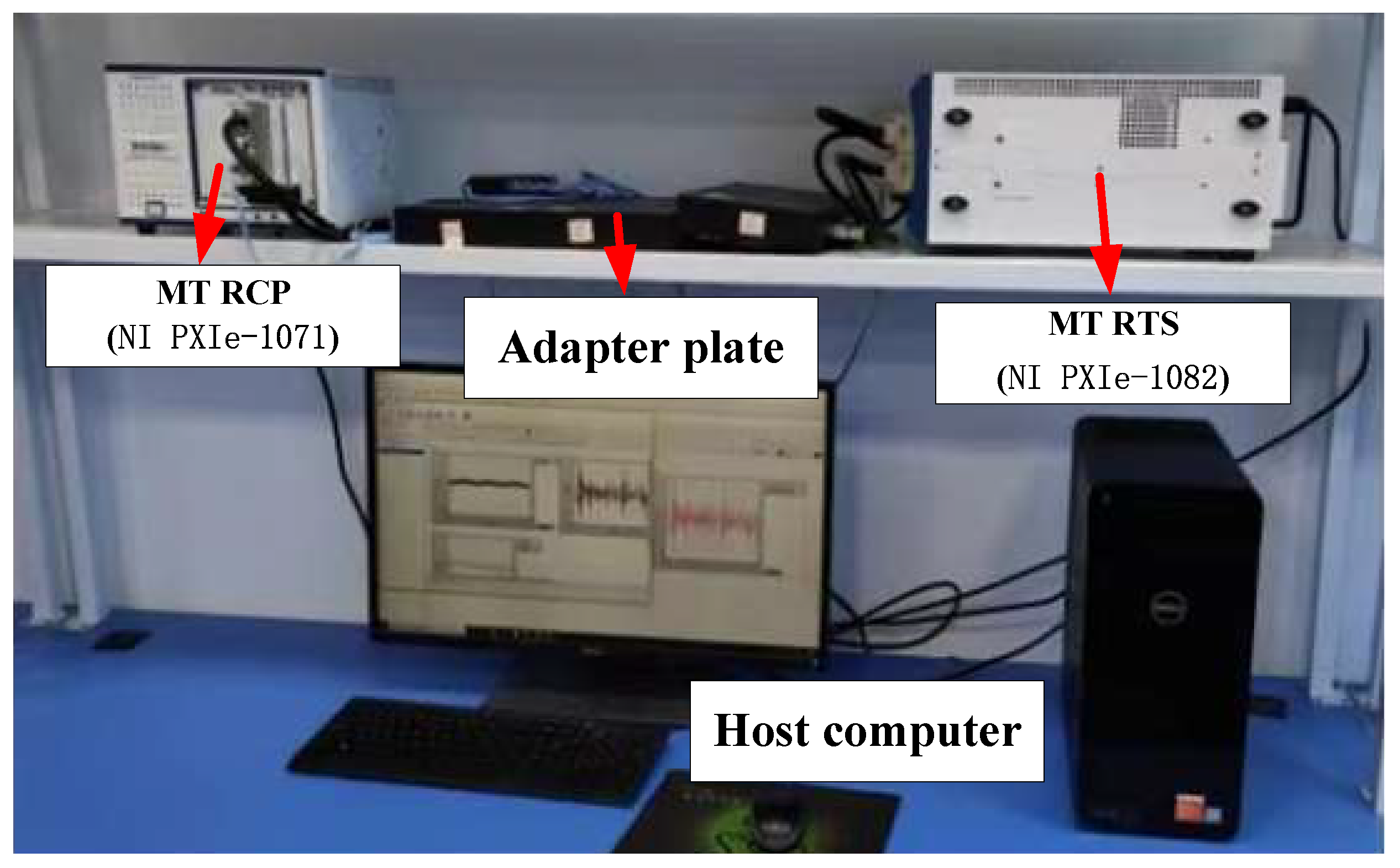
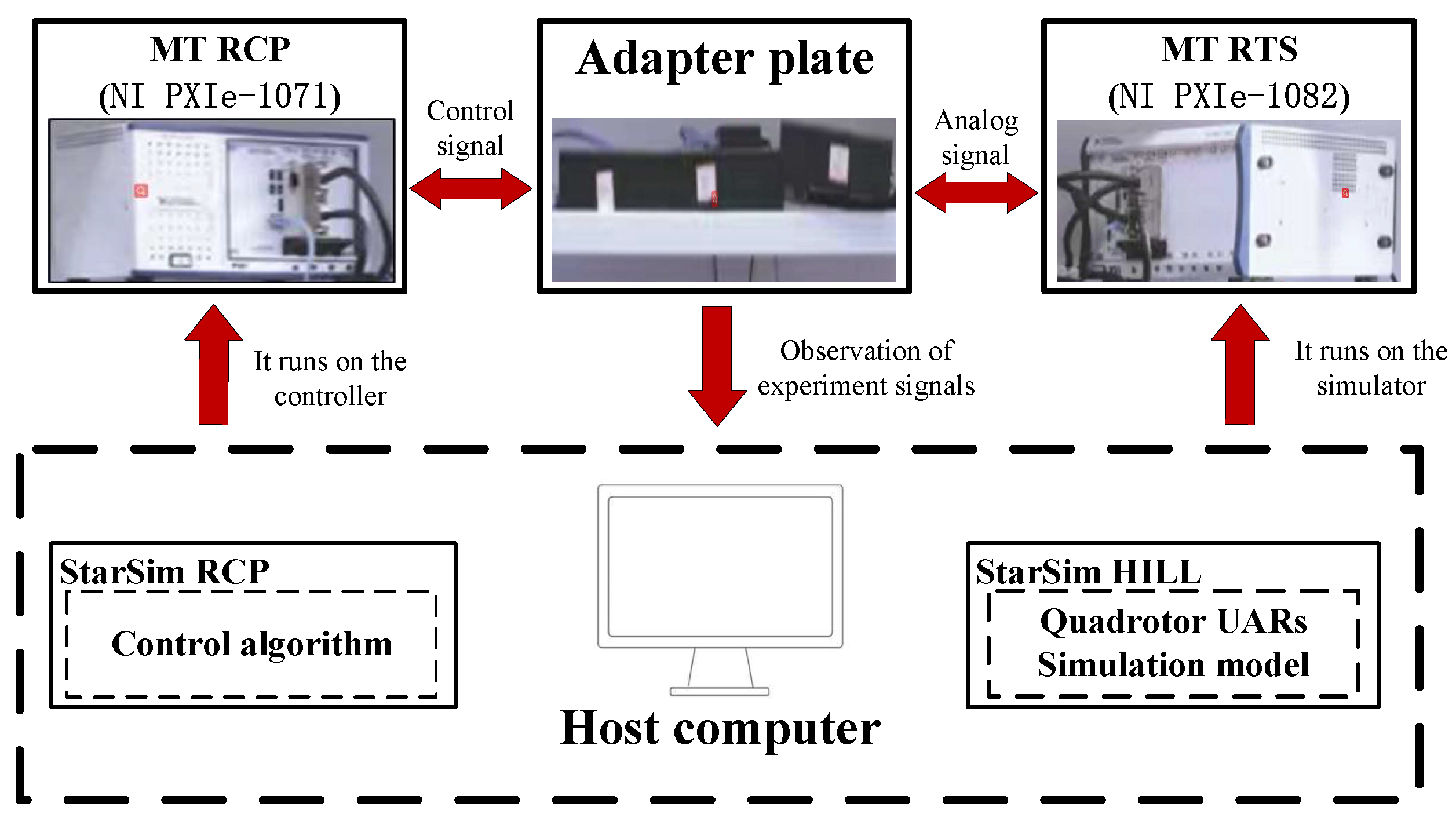
The hardware-loop platform was used for testing the proposed control method. Figure 3 and Figure 4 show the environment used for the actual experiment and the structure of the experimental system, respectively, where the following components were included: (1) a rapid control prototype (RCP), (2) a real-time simulator (RTS), (3) an adapter plate, and (4) a host computer.
Remark 2.
It should be noted that the control system was implemented in the hardware-in-loop simulation stage, as shown in Figure 3 (page 12), where the whole experimental platform was composed of four parts, namely, a real-time simulator (RTS), a rapid control prototype (RCP), an adapter plate, and a host computer. Compared with simulations conducted only on a host computer, hardware in the loop simulations are closer to actual physical control experiments conducted in real-world applications. In future works we will focus on field-testing the control of quadrotor UARs in the real world.
In the experiment, the reference trajectories { X d , Y d , Z d , ψ d } were selected as cos ( t ) , sin ( t ) , 0.5 t , 0 . The parameters of the control model are shown in Table 2.
Remark 3.
It should be noted that the instantaneous position of the quadrotor can be tracked accurately by looking for the experimental data at the corresponding time, and the real-time control based on the DSC method can also be achieved on the hardware-in-loop simulation platform.
For the high-gain-state observer in (13) we have A i , 0 = q i , 1 1 q i , 2 0 , q 1 = q 2 = 5 3 , q 3 = 1 10 , k i = 2 , Δ i 1 = 1 0 0 1 / k i , i = X , Y , Z .
The control algorithm parameters were chosen as follows: l X , 1 = 16 , l Y , 1 = 56 , l Z , 1 = 10 , l X , 2 = 48 , l Y , 2 = 168 ,   l Z , 2 = 100 , k 1 = 20 , k 2 = 60 , k 3 = 20 , k 4 = 60 , k 5 = 10 ,   k 6 = 26 , γ ϑ X = γ ϑ Y = γ ϑ Z = 3 , σ ϑ X = σ ϑ Y = σ ϑ Z = 0.5 , r Θ α 1 = 2 ,   r Θ α 2 = 0.02 , r Θ α 3 = 0.5 ,   σ Θ α 1 = 0.1 , σ Θ α 2 = 0.002 ,   σ Θ α 3 = 0.2 , g X , 1 = 1 , ρ X = 0.02 , g X = 0.001 , g Y , 1 = 3 , ρ Y = 0.05 , g Y = 0.001 , g Z , 1 = 2 ,   ρ Z = 0.06 , g Z = 0.001 , δ 1 = δ 2 = 0.005 , ψ ¯ 1 = ψ ¯ 2 = 6 , ψ 1 = ψ 2 = 0.05 , β 1 = β 2 = 8 ,   δ 3 = 0.02 , ψ ¯ 3 = 0.0002 , ψ 3 = , 0.08 , β 3 = 0.0001 . In addition, we included the time constants of a low-pass filter: τ X , 2 = τ Y , 2 = τ Z , 2 = τ 2 = τ 4 = τ 6 = 0.05 .
For the design of the position controller, the RBFNNs ψ i ξ i , i = X , Y , Z all had seven nodes. The centers of the base functions were –1, –0.8, –0.4, 0, 0.4, 0.8, 1, with the corresponding width η i , n , n = 1 7 and with ξ i = x ^ ^ i , 2 . Furthermore,
Ψ i T ξ = 0 0 0 ψ i , 2 ξ i = 0 0 0 ψ i 1 , 1 ξ i , 1 , , ψ i 1 , 7 ξ i , 1
According to [12], a comparative simulation which combined the BSMC scheme and the event-triggering mechanism was conducted.Moreover, the same model parameters and external disturbance of the quadrotor were also applied. Then, the tracking effects and tracking errors of the reference trajectories for the two methods, as well as the parameters of the control signal and the adaptive law, were presented in the simulation. Then, the reference trajectories of the roll and pitch angle were designed in the process of the control scheme. Thus, different control schemes would result in different attitude angle reference trajectories.
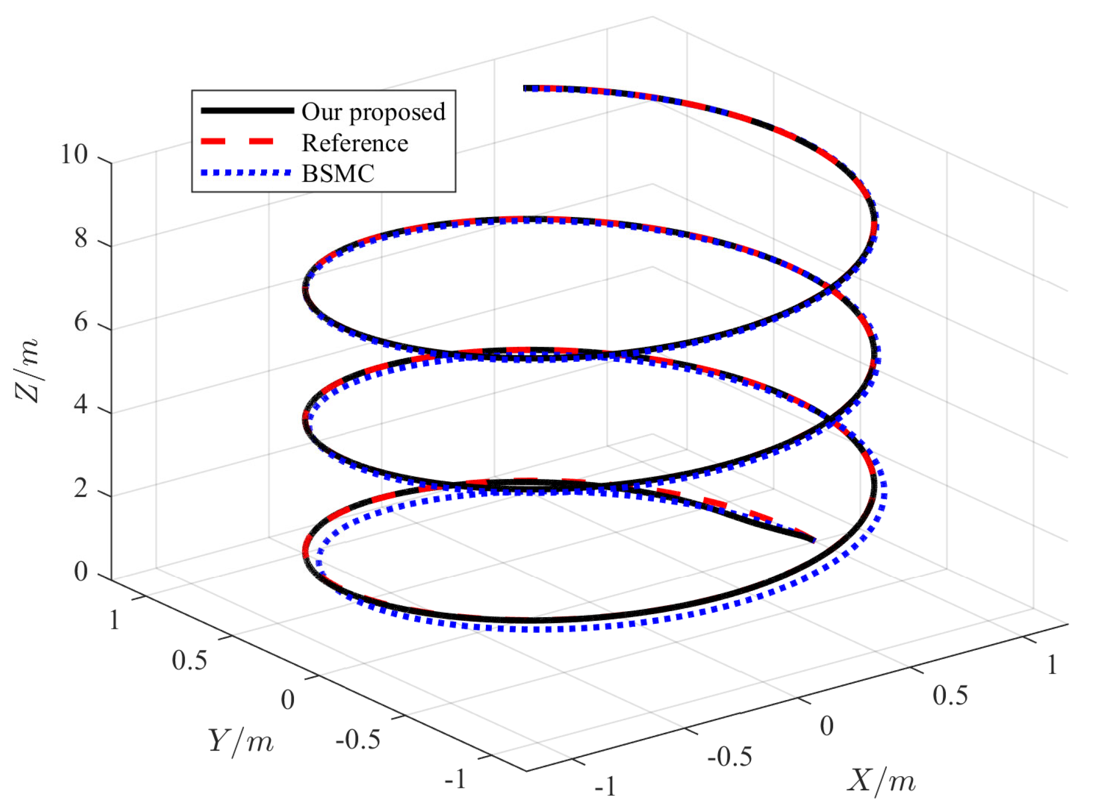
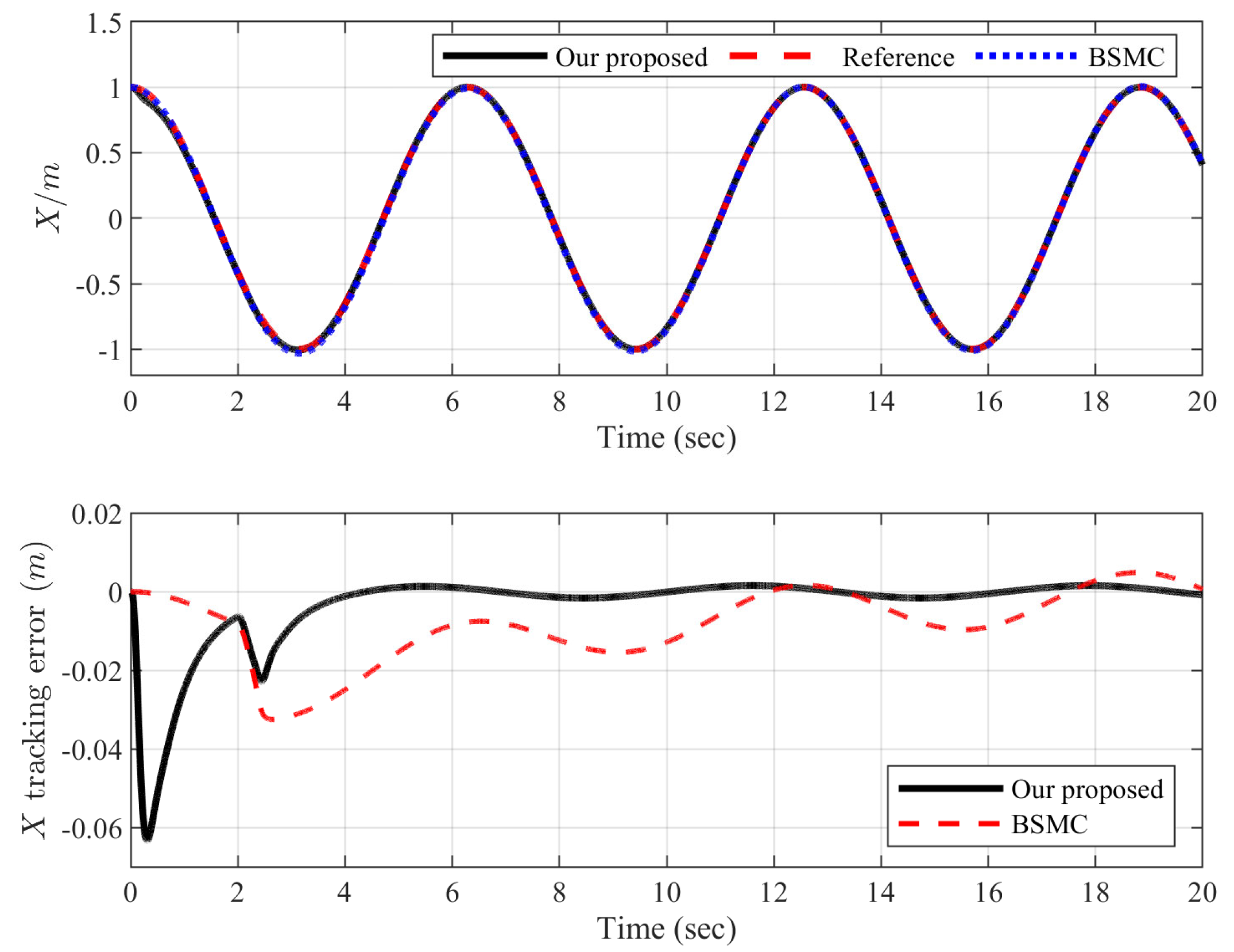
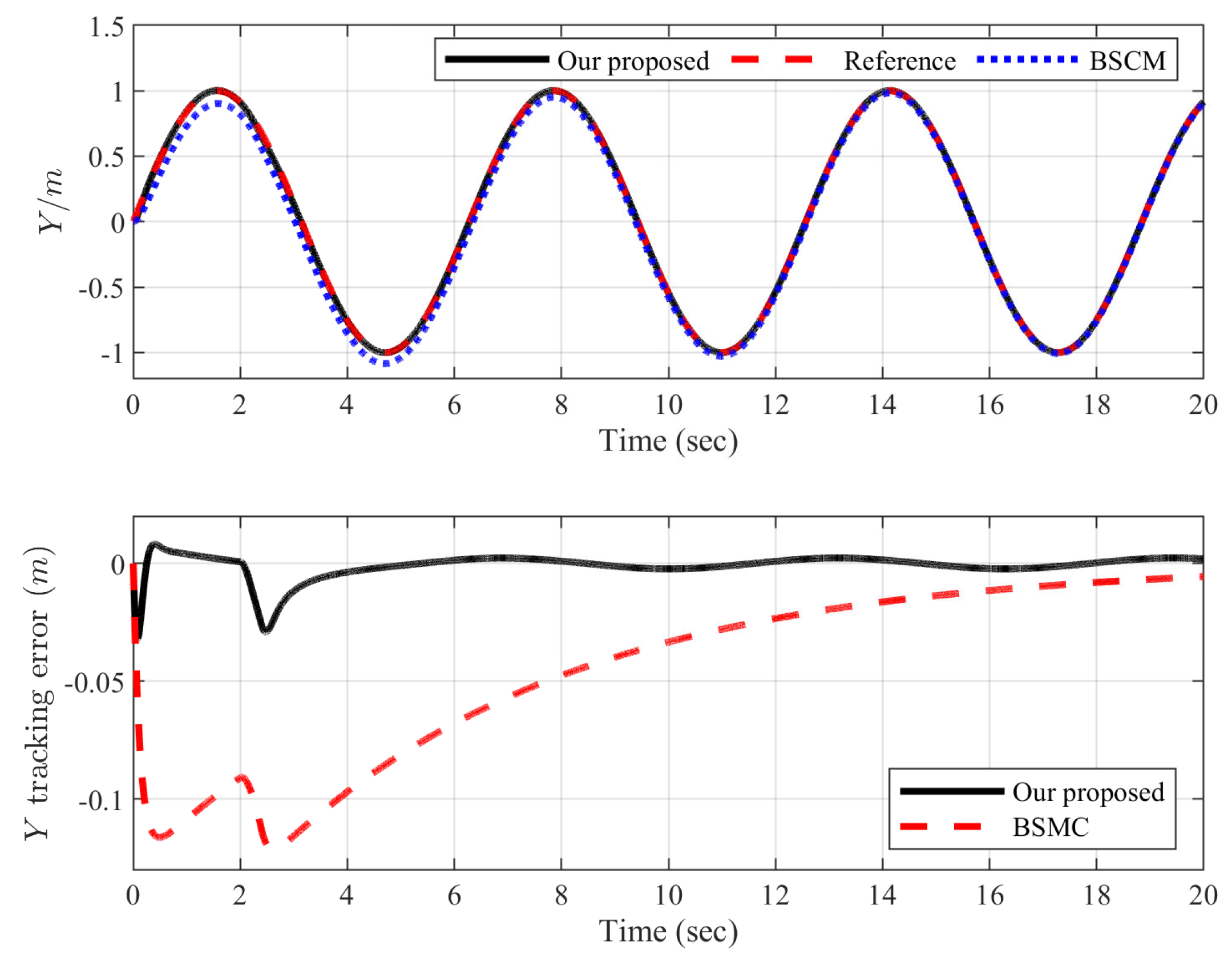
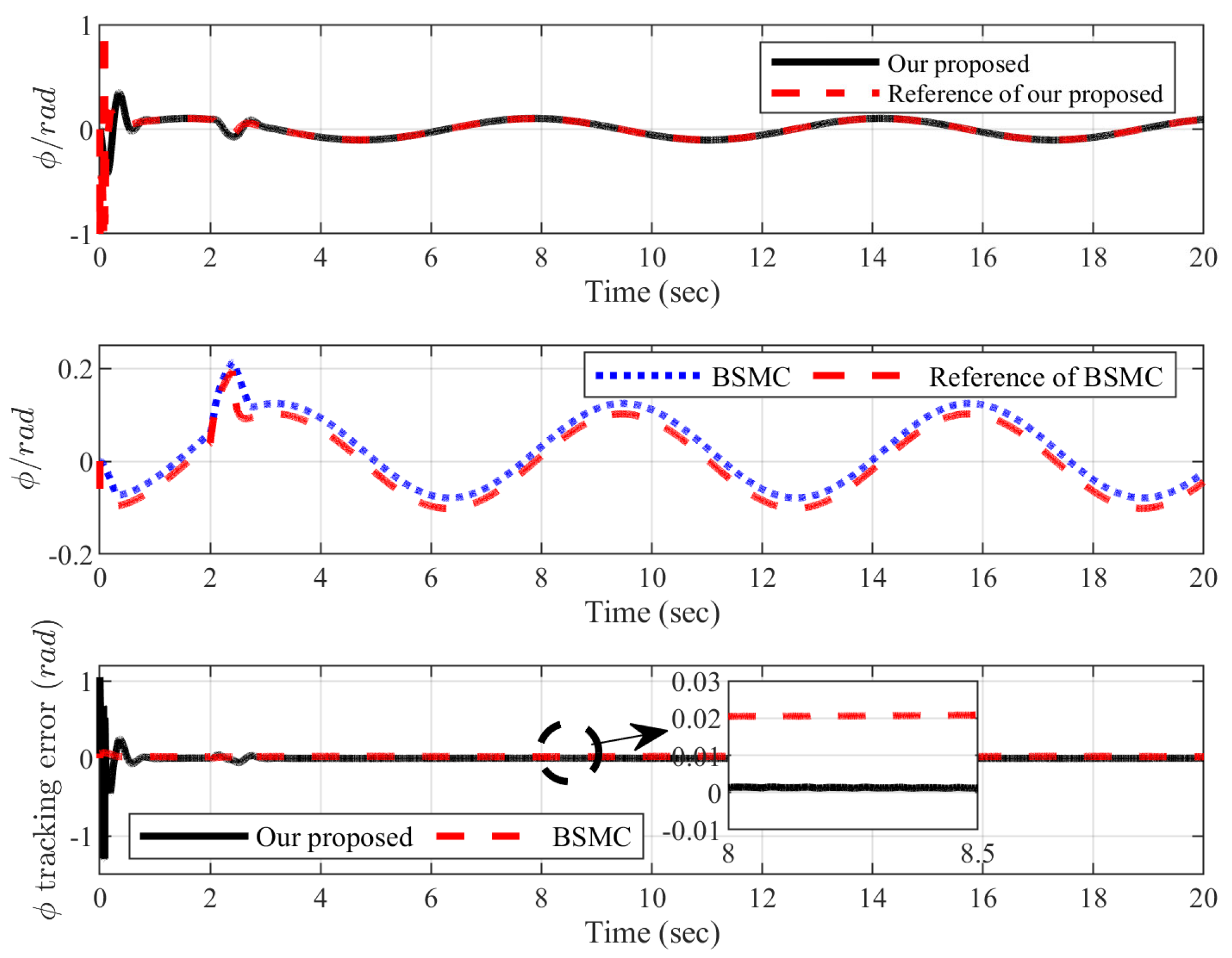
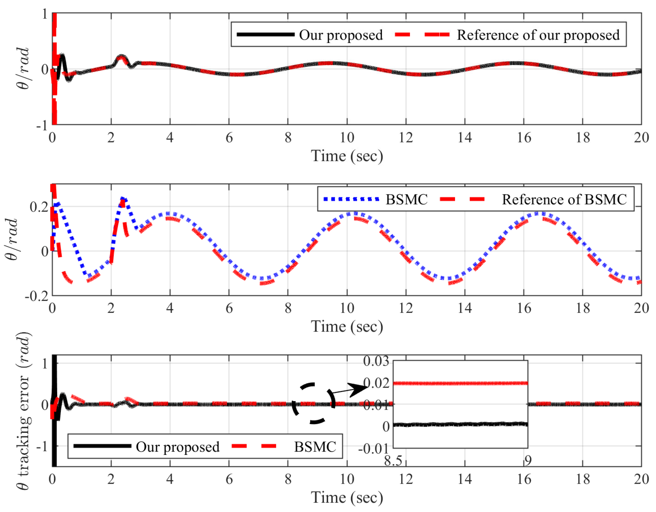
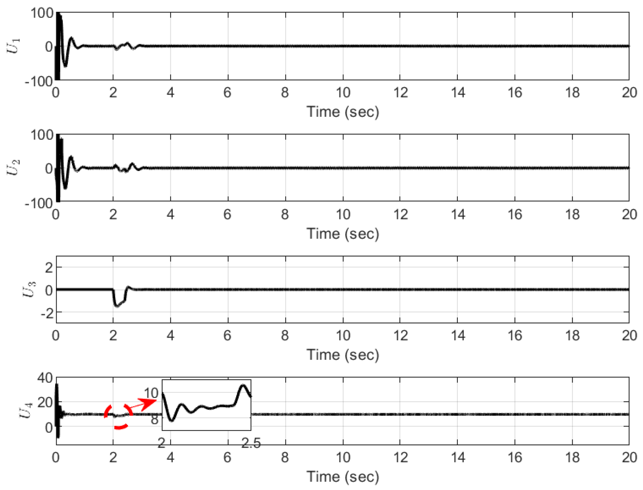
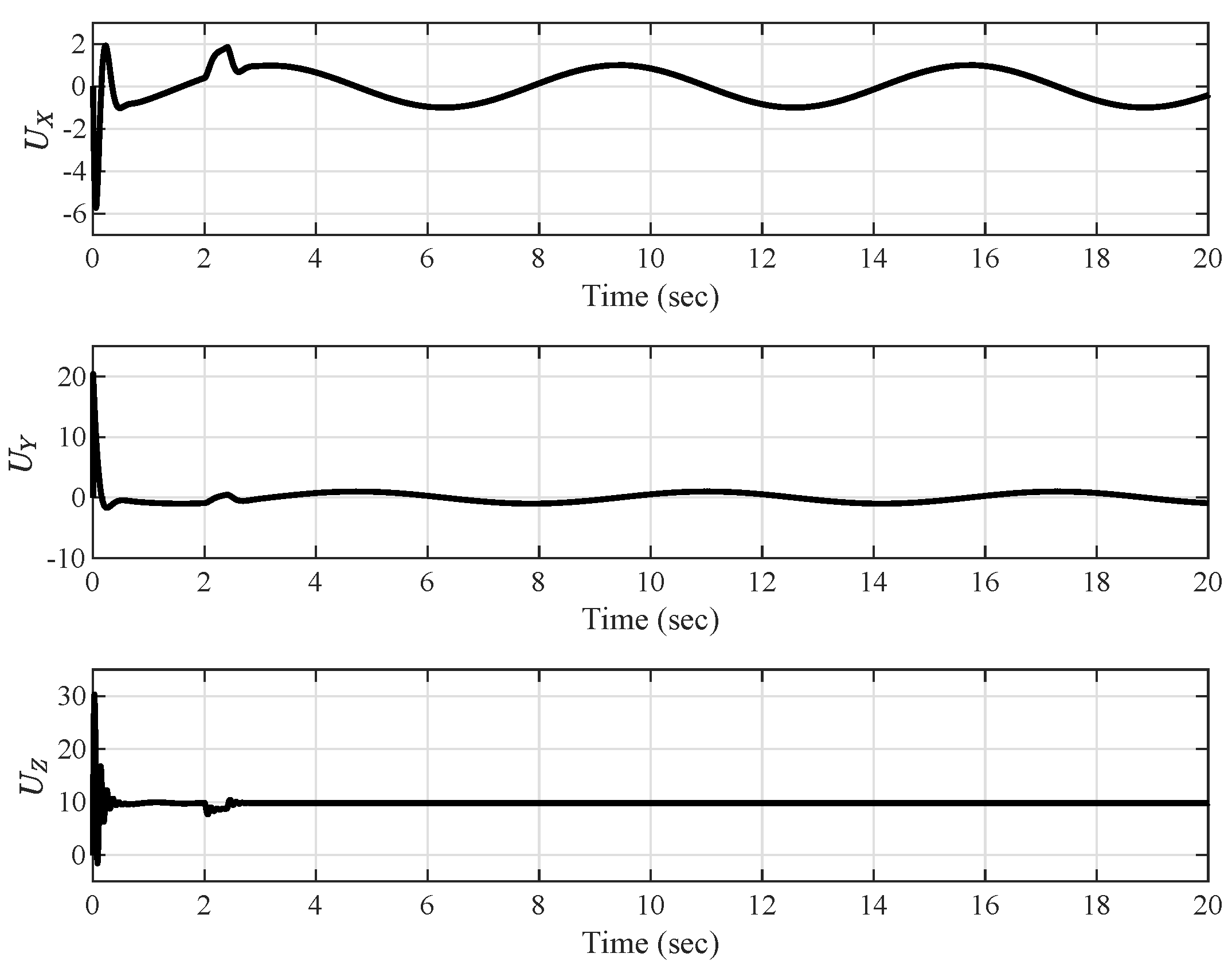
The experimental results of the positioning trajectory tracking are presented in Figure 5, Figure 6, Figure 7 and Figure 8 and the attitude tracking and errors are presented in Figure 9, Figure 10 and Figure 11. The control performance of the model presented in this paper can be observed in Figure 6, Figure 7, Figure 8, Figure 9, Figure 10 and Figure 11. Smaller tracking errors and a better tracking performance could be obtained compared to the BSMC method. Figure 12 presents the actual control signals U 1 to U 4 , and Figure 13 shows the control signals U X , U Y , U Z obtained in position tracking. As can be seen in Figure 12 and Figure 13, the updated frequencies of control signals were significantly reduced after the introduction of the event triggering mechanism. Figure 14 depicts the estimated values of ϑ X , ϑ Y , ϑ Z and the unknown parameters ϑ ^ X , ϑ ^ Y , ϑ ^ Z . In addition to evaluating the accuracy of the proposed scheme, the mean average error M A E = i = i s s N S 1 ( i ) / ( N i s s ) , N = 20 , 000 , i s s = 12,000 and the root mean squared error R M S E = i = i s s N S 1 2 ( i ) / ( N i s s ) , N = 20 , 000 , i s s = 12,000 were selected as metrics for study. The MAE and RMSE of the designed control strategy, as well as those of BSMC, are presented in Table 3 and Table 4.

5. Conclusions

A neural network and event-triggered-mechanism-based adaptive control method for the tracking control of a quadrotor UAR’s trajectory was proposed in this study. The system stability analysis and the experimental results showed that: (1) The unmeasurable state in the system was estimated by constructing a high gain filter observer, combined with the output feedback method. Under conditions in which position information was available, the “differential explosion” problem was overcome by means of a DSC control scheme, and good performance was obtained. (2) The update signal of the frequency was reduced by using the event-triggering control method properly and the robustness of our proposed method was tested. (3) The L tracking performance of the system was achieved by adopting the initialization technique and choosing the appropriate controller parameters. (4) Based on the outcomes of the hardware-in-loop simulation, we observed that our proposed control method exhibited good performance compared to that of the BSMC scheme. The proposed scheme provided 0.335%, 1.091%, 0.457%, 2.176%, 2.19%, and 1.126 × 10 6 lower mean average error (MAE) values compared to those of the BSMC algorithm in relation to X, Y, Z, ϕ , θ , and ψ , respectively.

Author Contributions

Conceptualization, X.Z. and G.Z.; methodology, C.-Y.S.; software, M.L.; validation, P.L. and M.L.; formal analysis, P.L. and M.L.; investigation, P.L. and M.L.; data curation, P.L. and M.L.; writing—original draft preparation, P.L. and M.L.; writing—review and editing, X.Z.; visualization, P.L. and M.L.; supervision, X.Z., G.Z. and Z.L.; project administration, X.Z. and G.Z.; funding acquisition, X.Z. and G.Z. All authors have read and agreed to the published version of the manuscript.

Funding

This research was funded by the Science and Technology Research Project of Education Department of Jilin Province grant number JJKH20220115KJ; Science and Technology Project of Jilin Province grant number 20210509053RQ; Innovation and Entrepreneurship Talent Funding Project of Jilin Province grant number 2021Y005.

Institutional Review Board Statement

Not applicable.

Informed Consent Statement

Not applicable.

Data Availability Statement

Not applicable.

Conflicts of Interest

The authors declare no conflict of interest.

Appendix A

Appendix A.1. Proof of Lemma 2

Define the following error transfer function:
ϵ ^ i = Δ i 1 ϵ i
ϵ ^ ˙ i = k i A i , 0 ϵ ^ i + Δ i 1 B i
x ^ ^ i = Δ i ς i , 0 + Δ i v i , 0 + Δ i Ξ i ϑ ^ i .
where A i , 0 denotes a Hurwitz matrix, and P ¯ i is the symmetric positive definite matrix that makes Equation (20) true and defines the quadratic function
V ϵ ^ i = ϵ ^ i T P ¯ i ϵ ^ i .
V ˙ ϵ ^ i = 2 k i ϵ ^ i T ϵ ^ i + 2 ϵ ^ i T P ¯ i Δ i 1 B i 2 k i ϵ ^ i 2 + 2 ϵ ^ i P ¯ i B i max / k i .
Through Young’s inequality, we can further obtain
V ˙ ϵ ^ i 2 k i ϵ ^ i 2 + k i ϵ ^ i 2 + 2 k i ( P ¯ i B i max k i 2 ) 2 k i λ max P ¯ i ϵ ^ i T P ¯ i ϵ ^ i + 2 k i ( P ¯ i B i max k i 2 ) 2
where λ max P ¯ i denotes the maximum eigenvalue of P ¯ i .
It follows that
V ϵ i = ϵ i T P i ϵ i = ϵ ^ i T P ¯ i ϵ ^ i = V ϵ ^ i , t 0 .

Appendix A.2. Proof of Theorem 1

Define
Ω i , 1 = y r i , y ˙ r i , y ¨ r i : y r i 2 + y ˙ r i 2 + y ¨ r i 2 G i , 0 Ω i , 2 = S i , 1 2 + S i , 2 2 + y i , 2 2 + 1 r ϑ i ϑ ˜ i 2 + 2 ϵ i T P i ϵ i 2 p Π j , 1 = y r j , y ˙ r j , y ¨ r j : y r j 2 + y ˙ r j 2 + y ¨ r j 2 H i , 0 Π j , 2 = S 2 j 1 2 + S 2 j 2 + y 2 j 2 + 1 r Θ α j Θ ˜ α j 2 2 p
with G i , 0 and H i , 0 being positive constants. In the compact Ω i , 1 × Ω i , 2 , the continuous function B i , 2 has the maximum value M i , 2 , i = X , Y , Z . Then, V ˙ in (58); it follows that
V ˙ = S i , 1 S ˙ i , 1 + S i , 2 S ˙ i , 2 + y i , 2 y ˙ i , 2 + 1 r ϑ i ϑ ˜ i T ϑ ^ ˙ i + V ˙ ϵ i + j = 1 6 S j S ˙ j + j = 1 3 1 r Θ α j Θ ˜ α j T Θ ^ ˙ α j + y 2 j y ˙ 2 j .
By using (52) and (53), we arrive at
y i , 2 y ˙ i , 2 y i , 2 2 τ i , 2 + y i , 2 2 M i , 2 2 2 κ i + κ i 2 y 2 j y ˙ 2 j y 2 j 2 τ 2 j + y 2 j 2 M 2 j 2 2 υ 2 j + υ 2 j 2
where κ i and υ 2 j are positive constants.
Since ϵ ^ i = Δ i 1 ϵ i , we have ϵ i , 2 2 = k i 2 ϵ ^ i , 2 2 k i 2 / λ min P ¯ i V ϵ ^ i = k i 2 / λ min P ¯ i V ϵ i . Using Young’s inequality, we can see that
S i , 1 ϵ i , 2 k i 2 2 S i , 1 2 + 1 λ min P ¯ i V ϵ i .
From (25), (56) and (A11), we can conclude that
S i , 1 S ˙ i , 1 l i , 1 k i 2 k i 2 2 S i , 1 2 + k i 2 y i , 2 2 + k i S i , 1 S i , 2 ϑ ˜ i T k i Ξ i , ( 2 ) T S i , 1 + 1 2 λ min P ¯ i V ϵ i
S 2 j 1 S ˙ 2 j 1 ( k 2 j 1 1 ) S 2 j 1 2 + 1 2 S 2 j 2 + 1 2 y 2 j 2 .
Similarly, using (30), one observes that
S i , 2 S ˙ i , 2 = k i q i , 2 v i , ( 0 , 1 ) S i , 2 + k i 1 U i S i , 2 z ˙ 2 S i , 2
For t t j , t j + 1 , we have
U ˘ i ( t ) U i ( t ) g ,
and there is always a λ t satisfying λ t j = 0 , λ t j + 1 = ± 1 , that is, λ t 1 , and thus, (A15) with:
U ˘ i ( t ) = U i ( t ) + λ t g .
From (A14) and (A16), one can observe that
S i , 2 S ˙ i , 2 = k i q i , 2 v i , ( 0 , 1 ) S i , 2 + k i 1 S i , 2 U ˘ i ( t ) λ t g z ˙ 2 S i , 2
Substituting (32) into (A17), it follows that:
S i , 2 S ˙ i , 2 = l i , 2 S i , 2 2 + k i 1 S i , 2 g 1 tanh k 1 S i , 2 g 1 ρ λ t g .
Note that t a n h ( · ) denotes the hyperbolic tangent function, which has the following characteristics:
0 α α tanh α β 0.2785 β
where α > 0 , β R . From (A18) and (A19), it follows that
S i , 2 S ˙ i , 2 l i , 2 S i , 2 2 + 0.2785 β .
In the same way, we have:
S 2 j S ˙ 2 j k 2 j S 2 j 2 1 2 S 2 j 2 Θ ˜ α j T Γ α j S 2 j + 1 2 d j 2 t + 0.2785 ρ .
Noting the adaptive law (27), it follows that:
1 r ϑ i ϑ ˜ i T ϑ ^ ˙ i = ϑ ˜ i T k i Ξ i , ( 2 ) T S i , 1 σ ϑ i ϑ ˜ i T ϑ ^ i 1 r Θ α j Θ ˜ α j T Θ ^ ˙ α j = Θ ˜ α j T Γ α j S 2 j σ Θ α j Θ ˜ α j T Θ ^ α j
According to the definition of ϑ ˜ i and Θ ^ α j , we can observe that
σ ϑ i ϑ ˜ i T ϑ ^ i = σ ϑ i ϑ ˜ i T ϑ ˜ i + ϑ i * σ ϑ i 2 ϑ ˜ i T ϑ ˜ i + σ ϑ i 2 ϑ i * T ϑ i * σ Θ α j Θ ˜ α j T Θ ^ α j = σ Θ α j Θ ˜ α j T Θ ˜ α j + Θ α j σ Θ α j 2 Θ ˜ α j T Θ ˜ α j + σ Θ α j 2 Θ α j T Θ α j .
Substituting (A10), (A13), (A20), and (A21)–(A23) into (A9), it follows that:
V ˙ l i , 1 k i k i 2 2 S i , 1 2 l i , 2 k i 2 S i , 2 2 σ ϑ i 2 ϑ ˜ i T ϑ ˜ i + σ ϑ i 2 ϑ i * T ϑ i * + k i 2 1 τ i , 2 + M i , 2 2 2 κ i y i , 2 2 + 0.8355 β + 1 2 λ min P ¯ i k i λ max P ¯ i V ϵ i + 2 k i ( P ¯ i B i max k i 2 ) 2 + j = 1 3 ( k 2 j 1 1 ) S 2 j 1 2 k 2 j S 2 j 2 + 1 2 y 2 j 2 + 1 2 d j 2 t σ Θ α j 2 Θ ˜ α j T Θ ˜ α j + σ Θ α j 2 Θ α j T Θ α j y 2 j 2 τ 2 j + y 2 j 2 M 2 j 2 2 υ 2 j + υ 2 j 2 + 0.8355 ρ .
By choosing the following design parameters:
k i 2 λ max P ¯ i c i , 1 + λ max P ¯ i / 2 λ min P ¯ i l i , 1 k i 2 / 2 + k i + c i , 1 l i , 2 k i / 2 + c i , 1 1 τ i , 2 k i / 2 + M i , 2 2 / ( 2 κ i ) + c i , 1 σ ϑ i 2 c i , 1 / r ϑ i c i , 2 = σ ϑ i ϑ i * T ϑ i * / 2 + k i / 2 + 2 k i ( P ¯ i B i max / k i 2 ) 2 + 0.8355 β 1 / τ 2 j 1 / 2 + M 2 j 2 / ( 2 υ 2 j ) + c j , 1 k 2 j 1 1 + c j , 1 k 2 j c j , 1 σ Θ α j 2 c j , 1 / r Θ α j c j , 2 = σ Θ α j Θ α j T Θ α j / 2 + υ 2 j / 2 + d j 2 t / 2 + 0.8355 ρ
where c i , 1 and c j , 1 satisfy c i , 1 c i , 2 / ( 2 G 1 ) and c j , 1 c j , 2 / ( 2 G 1 ) , i = X , Y , Z , j = 1 , 2 , 3 , respectively. According to (A24), one has
V ˙ 2 C 1 V + C 2
where C 1 = min c X , 1 , c Y , 1 , c Z , 1 , c 1 , 1 , c 2 , 1 , c 3 , 1 , C 2 = c X , 2 + c Y , 2 + c Z , 2 + c 1 , 2 + c 2 , 2 + c 3 , 2 . It can be seen that V ˙ 0 , whereas V = G 1 , which means that V t G 1 is an invariant set. For all t 0 , if V 0 G 1 , there must be V t G 1 . Therefore, V is uniformly bounded. By solving the inequality in (A26), we have:
V t C 2 / 2 C 1 + e 2 C 1 t V 0 C 2 / 2 C 1 , t 0 ,
which implies that lim t V t C 2 / 2 C 1 . It should be noted that the value of C 1 in (A26) is chosen based on the minimum value of c i , 1 , i = X , Y , Z , 1 , 2 , 3 . This indicates that when the above design parameters values are large enough, a large enough value of C 1 can be obtained.Thus, C 2 is a constant defined in (A26), meaning that C 2 / ( 2 C 1 ) can also be small enough.
In order to obtain L tracking performance, let:
y r i ( 0 ) = y i ( 0 ) S i , 1 ( 0 ) = 0 v i , 0 ( 0 ) = 0 ς i , ( 0 , 1 ) ( 0 ) = 0 Ξ i ( 0 ) = 0 ϑ ^ i ( 0 ) = 0 S 2 j 1 ( 0 ) = 0 Θ ^ α j ( 0 ) = 0 x 2 j 1 r ( 0 ) = x 2 j 1 ( 0 ) .
where ς i , ( 0 , 1 ) ( 0 ) = y i ( 0 ) = x i , 1 ( 0 ) . We have V t C 2 / 2 C 1 + λ max P ¯ i ϵ i ( 0 ) 2 / k i 2 ,   i = X , Y , Z . According to (A24), we have S 2 j 1 = sup t 0 S 2 j 1 = x 1 x 1 r C 2 / 2 C 1 , S i , 1 = sup t 0 S i , 1 = x i , 1 y r i C 2 / 2 C 1 + λ max P ¯ i ϵ i ( 0 ) 2 / k i 2 , i = X , Y , Z , j = 1 , 2 , 3 , which means that the tracking error of L norm S i , 1 ,   S 2 j 1 , could be made arbitrarily small by selecting the appropriate parameters. The proof of Theorem 1 is completed.

Appendix A.3. Proof of Theorem 2

Take the event-triggered controller designed for the position subsystem as an example. Thus, we have t t n , t n + 1 , from (33), wherein:
d d t e = s i g n e e ˙ U ˘ ˙ i ( t ) .
From (32), one has:
U ˘ ˙ i ( t ) = U ˙ i ( t ) g i , 1 2 k 1 ϵ i cosh 2 k 1 S i , 2 g i , 1 ϵ i .
Since each item in (A30) is globally bounded, we can observe that U ˘ ˙ i ( t ) are continuous and bounded; that is, there must be μ > 0 such that U ˘ ˙ i ( t ) μ . Furthermore, at t n , e t n = 0 , as well as when t t n + 1 , e ( t n + 1 ) = g i . Therefore, there must be a positive constant t = t n + 1 t n that satisfies t > g i / μ , which indicates that the time interval t of event triggering has a lower bound; thus, Zeno behavior can be avoided. In the same way, the controller based on an event-triggered mechanism has been designed for attitude tracking, which can also effectively avoid the occurrence of Zeno behavior.

References

  1. Shakhatreh, H.; Sawalmeh, A.H.; Al-Fuqaha, A.; Dou, Z.; Almaita, E.; Khalil, I.; Othman, N.S.; Khreishah, A.; Guizani, M. Unmanned aerial vehicles (UAVs): A survey on civil applications and key research challenges. IEEE Access 2019, 7, 48572–48634. [Google Scholar] [CrossRef]
  2. Saeed, A.S.; Younes, A.B.; Cai, C.; Cai, G. A survey of hybrid unmanned aerial vehicles. Prog. Aerosp. Sci. 2018, 98, 91–105. [Google Scholar] [CrossRef]
  3. Lu, Y.; Macias, D.; Dean, Z.S.; Kreger, N.R.; Wong, P.K. A UAV-mounted whole cell biosensor system for environmental monitoring applications. IEEE Trans. Nanobiosci. 2015, 14, 811–817. [Google Scholar] [CrossRef] [PubMed] [Green Version]
  4. Zhang, X.; Lin, Y.; Wang, J. High-gain observer based decentralised output feedback control for interconnected nonlinear systems with unknown hysteresis input. Int. J. Control. 2013, 86, 1046–1059. [Google Scholar] [CrossRef]
  5. Liu, H.; Zhao, W.; Zuo, Z.; Zhong, Y. Robust control for quadrotors with multiple time-varying uncertainties and delays. IEEE Trans. Ind. Electron. 2016, 64, 1303–1312. [Google Scholar] [CrossRef]
  6. Wu, D.; Chen, X.; Yang, L.; Fu, G.; Shi, X. Compact and low-profile omnidirectional circularly polarized antenna with four coupling arcs for UAV applications. IEEE Antennas Wirel. Propag. Lett. 2017, 16, 2919–2922. [Google Scholar] [CrossRef]
  7. Zhang, Y.; Chen, Z.; Zhang, X.; Sun, Q.; Sun, M. A novel control scheme for quadrotor UAV based upon active disturbance rejection control. Aerosp. Sci. Technol. 2018, 79, 601–609. [Google Scholar] [CrossRef]
  8. Zhang, D.W.; Liu, G.P. Output feedback predictive control for discrete quasilinear systems with application to spacecraft flying-around. Asian J. Control. 2021, 24, 1846–1861. [Google Scholar] [CrossRef]
  9. Yang, H.; Cheng, L.; Xia, Y.; Yuan, Y. Active disturbance rejection attitude control for a dual closed-loop quadrotor under gust wind. IEEE Trans. Control. Syst. Technol. 2017, 26, 1400–1405. [Google Scholar] [CrossRef]
  10. Ma, Z.; Jiao, S.M. Research on the attitude control of quad-rotor UAV based on active disturbance rejection control. In Proceedings of the 2017 3rd IEEE International Conference on Control Science and Systems Engineering (ICCSSE), Beijing, China, 17–19 August 2017; pp. 45–49. [Google Scholar]
  11. Li, S.; Wang, Y.; Tan, J.; Zheng, Y. Adaptive RBFNNs/integral sliding mode control for a quadrotor aircraft. Neurocomputing 2016, 216, 126–134. [Google Scholar] [CrossRef]
  12. Chen, F.; Jiang, R.; Zhang, K.; Jiang, B.; Tao, G. Robust backstepping sliding-mode control and observer-based fault estimation for a quadrotor UAV. IEEE Trans. Ind. Electron. 2016, 63, 5044–5056. [Google Scholar] [CrossRef]
  13. Xu, L.X.; Ma, H.J.; Guo, D.; Xie, A.H.; Song, D.L. Backstepping sliding-mode and cascade active disturbance rejection control for a quadrotor UAV. IEEE/ASME Trans. Mechatron. 2020, 25, 2743–2753. [Google Scholar] [CrossRef]
  14. Almakhles, D.J. Robust backstepping sliding mode control for a quadrotor trajectory tracking application. IEEE Access 2019, 8, 5515–5525. [Google Scholar] [CrossRef]
  15. Shi, X.; Hu, B.; Yin, C.; Cheng, Y.; Huang, X. Design of trajectory tracking controller with fractional-order backstepping sliding mode method for quadrotor UAV. In Proceedings of the 2018 Chinese Control And Decision Conference (CCDC), Shenyang, China, 9–11 June 2018; pp. 5960–5965. [Google Scholar]
  16. Shao, X.; Liu, J.; Cao, H.; Shen, C.; Wang, H. Robust dynamic surface trajectory tracking control for a quadrotor UAV via extended state observer. Int. J. Robust Nonlinear Control 2018, 28, 2700–2719. [Google Scholar] [CrossRef]
  17. Shen, Z.; Li, F.; Cao, X.; Guo, C. Prescribed performance dynamic surface control for trajectory tracking of quadrotor UAV with uncertainties and input constraints. Int. J. Control 2020, 94, 1–21. [Google Scholar] [CrossRef]
  18. Muñoz, F.; González-Hernández, I.; Salazar, S.; Espinoza, E.S.; Lozano, R. Second order sliding mode controllers for altitude control of a quadrotor UAS: Real-time implementation in outdoor environments. Neurocomputing 2017, 233, 61–71. [Google Scholar] [CrossRef]
  19. Nowzari, C.; Cortés, J. Distributed event-triggered coordination for average consensus on weight-balanced digraphs. Automatica 2016, 68, 237–244. [Google Scholar] [CrossRef] [Green Version]
  20. Fan, Y.; Yang, Y.; Zhang, Y. Sampling-based event-triggered consensus for multi-agent systems. Neurocomputing 2016, 191, 141–147. [Google Scholar] [CrossRef]
  21. You, X.; Hua, C.; Guan, X. Event-triggered leader-following consensus for nonlinear multiagent systems subject to actuator saturation using dynamic output feedback method. IEEE Trans. Autom. Control. 2018, 63, 4391–4396. [Google Scholar] [CrossRef]
  22. Zeng, W.; Fan, H.; Wang, W. Event-triggered Adaptive Attitude Tracking Control of a Quadrotor UAV. In Proceedings of the 2019 Chinese Control And Decision Conference (CCDC), Nanchang, China, 3–5 June 2019; pp. 2855–2860. [Google Scholar]
  23. Wang, C.; Guo, L.; Wen, C.; Hu, Q.; Qiao, J. Event-triggered adaptive attitude tracking control for spacecraft with unknown actuator faults. IEEE Trans. Ind. Electron. 2019, 67, 2241–2250. [Google Scholar] [CrossRef]
  24. Yu, H.; Chen, X.; Chen, T.; Hao, F. Event-triggered bipartite consensus for multiagent systems: A Zeno-free analysis. IEEE Trans. Autom. Control 2019, 65, 4866–4873. [Google Scholar] [CrossRef]
  25. Yu, H.; Chen, T. On Zeno behavior in event-triggered finite-time consensus of multiagent systems. IEEE Trans. Autom. Control 2020, 66, 4700–4714. [Google Scholar] [CrossRef]
  26. Borgers, D.P.; Heemels, W.M.H. Event-separation properties of event-triggered control systems. IEEE Trans. Autom. Control 2014, 59, 2644–2656. [Google Scholar] [CrossRef]
  27. Xing, L.; Wen, C.; Liu, Z.; Su, H.; Cai, J. Event-triggered adaptive control for a class of uncertain nonlinear systems. IEEE Trans. Autom. Control 2016, 62, 2071–2076. [Google Scholar] [CrossRef]
  28. Huang, J.; Wang, Q.G. Event-triggered adaptive control of a class of nonlinear systems. ISA Trans. 2019, 94, 10–16. [Google Scholar] [CrossRef]
  29. Wang, C.; Wen, C.; Hu, Q. Event-triggered adaptive control for a class of nonlinear systems with unknown control direction and sensor faults. IEEE Trans. Autom. Control 2020, 65, 763–770. [Google Scholar] [CrossRef]
  30. Liang, H.; Liu, G.; Zhang, H.; Huang, T. Neural-network-based event-triggered adaptive control of nonaffine nonlinear multiagent systems with dynamic uncertainties. IEEE Trans. Neural Netw. Learn. Syst. 2020, 32, 2239–2250. [Google Scholar] [CrossRef]
  31. Zhu, G.; Wang, S.; Sun, L.; Ge, W.; Zhang, X. Output feedback adaptive dynamic surface sliding-mode control for quadrotor UAVs with tracking error constraints. Complexity 2020, 2020, 8537198. [Google Scholar] [CrossRef]
  32. Alexis, K.; Nikolakopoulos, G.; Tzes, A. Model predictive quadrotor control: Attitude, altitude and position experimental studies. IET Control Theory Appl. 2012, 6, 1812–1827. [Google Scholar] [CrossRef] [Green Version]
  33. Sanner, R.M.; Slotine, J. Gaussian networks for direct adaptive control. IEEE Trans. Neural Netw. 1992, 3, 837–863. [Google Scholar] [CrossRef]
  34. Zhang, X.; Wang, Y.; Zhu, G.; Chen, X.; Li, Z.; Wang, C.; Su, C.Y. Compound adaptive fuzzy quantized control for quadrotor and its experimental verification. IEEE Trans. Cybern. 2020, 51, 1121–1133. [Google Scholar] [CrossRef] [PubMed]
  35. KrstiC, M.; Kanellakopoulos, I.; KokotoviC, P.V. Nonlinear design of adaptive controllers for linear systems. IEEE Trans. Autom. Control 1994, 39, 738–752. [Google Scholar] [CrossRef] [Green Version]
  36. Esfandiari, F.; Khalil, H.K. Output feedback stabilization of fully linearizable systems. Int. J. Control 1992, 56, 1007–1037. [Google Scholar] [CrossRef]
  37. Zhang, X.; Wang, Y.; Wang, C.; Su, C.Y.; Li, Z.; Chen, X. Adaptive estimated inverse output-feedback quantized control for piezoelectric positioning stage. IEEE Trans. Cybern. 2018, 49, 2106–2118. [Google Scholar] [CrossRef] [PubMed]
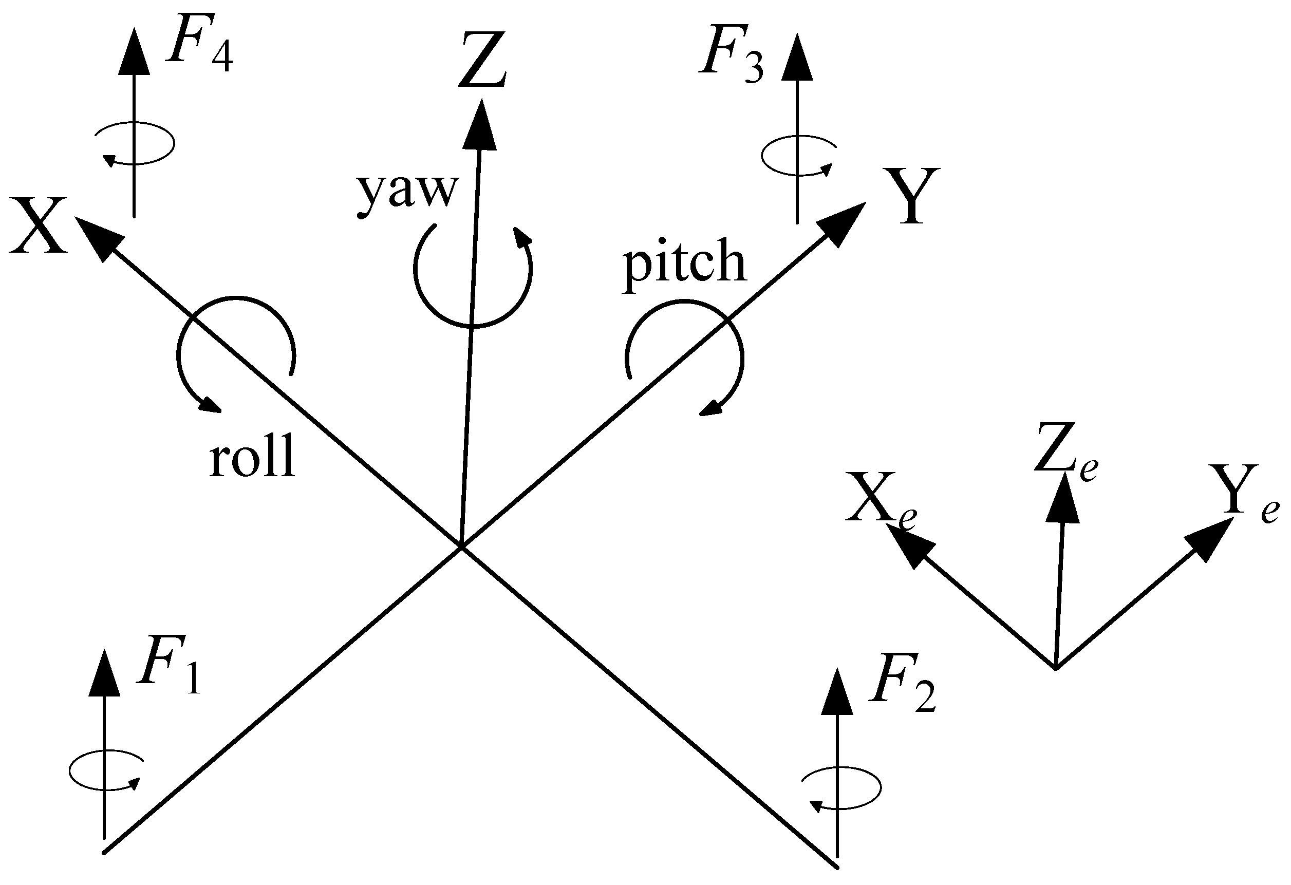
Figure 1. Quadrotor body coordinate system and ground coordinate system.
Machines 10 00617 g001
Figure 2. The architecture of the proposed control method.
Machines 10 00617 g002
Figure 3. The environment used for the actual experiment.
Machines 10 00617 g003
Figure 4. The structure of the experimental system.
Machines 10 00617 g004
Figure 5. Diagram of the control performance in space.
Machines 10 00617 g005
Figure 6. The control performance and tracking errors in relation to x.
Machines 10 00617 g006
Figure 7. The control performance and tracking errors in relation to y.
Machines 10 00617 g007
Figure 8. The control performance and tracking errors in relation to z.
Machines 10 00617 g008
Figure 9. The control performance and tracking errors in relation to the roll angle.
Machines 10 00617 g009
Figure 10. The tracking performance and tracking errors in relation to the pitch angle.
Machines 10 00617 g010
Figure 11. The control performance and tracking errors in relation to the yaw angle.
Machines 10 00617 g011
Figure 12. Control signals U 1 to U 4 .
Machines 10 00617 g012
Figure 13. The control signals.
Machines 10 00617 g013
Figure 14. The estimation of adaptive parameters ϑ X , ϑ Y , ϑ Z .
Machines 10 00617 g014
Table 1. The notation for the quadrotor.
SymbolNomenclature
F i , i = 1 , 2 , 3 , 4 Lift force
K X , K Y , K Z Unknown coefficients of air resistance
mMass of quadrotor
gAcceleration of gravity
ω ¯ Relative speed of the cross-coupled rotor
I x , I y , I z Rotary inertia for all axis
I r Moment of inertia for all motors
d ϕ , d θ , d ψ Coefficient of unknown aerodynamic drag
lDistance from the center to the rotor
τ i , i = 1 , 2 , 3 , 4 Torque
d X ( t ) , d Y ( t ) , d Z ( t ) , d 1 ( t ) , d 2 ( t ) , d 3 ( t ) Bounded external disturbances
Table 2. The design parameters of the quadrotor.
SymbolValueUnits
m1.4kg
k2.98 10 6 N · s 2 · rad 2
l0.2m
τ 1.14 10 7 N · s 2 · rad 2
d ϕ , d θ , d ψ 1.2 10 2 N · s 2 · rad 2
J x 1.8 N · s 2 · rad 2
J y 1.8 N · s 2 · rad 2
J z 2.4 N · s 2 · rad 2
Table 3. MAE and RMSE of position tracking.
SchemeMAERMSE
XYZXYZ
BSMC0.427%1.247%0.779%0.520%1.344%0.845%
Our proposed method0.092%0.156%0.322%0.104%0.171%0.352%
Table 4. MAE and RMSE of angle tracking.
SchemeMAERMSE
ϕ θ ψ ϕ θ ψ
BSMC2.258%2.288%1.137 × 10 6 2.264%2.299 %1.306 × 10 6
Our proposed method0.082%0.098%1.148 × 10 8 0.093%0.108%1.282 × 10 8
Publisher’s Note: MDPI stays neutral with regard to jurisdictional claims in published maps and institutional affiliations.