Article

Image Based Visual Servoing for Floating Base Mobile Manipulator Systems with Prescribed Performance under Operational Constraints

by
George C. Karras
1,*,
George K. Fourlas
1,
Alexandros Nikou
2,
Charalampos P. Bechlioulis
3 and
Shahab Heshmati-Alamdari
4
1
Department of Informatics and Telecommunications, University of Thessaly, 35100 Lamia, Greece
2
Ericsson Research, Artificial Intelligence, 164 83 Stockholm, Sweden
3
Division of Systems and Control, Department of Electrical and Computer Engineering, University of Patras, 26504 Patras, Greece
4
Section of Automation & Control, Department of Electronic Systems, Aalborg University, 9220 Aalborg, Denmark
*
Author to whom correspondence should be addressed.
Machines 2022, 10(7), 547; https://doi.org/10.3390/machines10070547
Submission received: 2 June 2022 / Revised: 29 June 2022 / Accepted: 4 July 2022 / Published: 6 July 2022
(This article belongs to the Section Robotics, Mechatronics and Intelligent Machines)

Abstract

:
This paper presents a novel Image-Based Visual Servoing (IBVS) control approach for Floating Base Mobile Manipulator Systems (FBMMSs) that imposes prescribed transient and steady-state response on the image feature coordinate errors while satisfying the visibility constraints that arise owing to the camera’s limited field of view. The proposed control strategy does not incorporate any knowledge on either the FBMMS dynamic model, the exogenous disturbances, or the inevitable camera calibration and depth measurement errors. More specifically, it guarantees: (i) predefined behavior in terms of overshoot, convergence rate, and maximum steady-state error value of the image features and system velocities tracking errors; (ii) satisfaction of camera field of view constraints; (iii) bounded closed-loop control signals, and (iv) reduced design and implementation complexity. Additionally, the performance of the developed scheme is solely determined by certain designer-specified performance functions/parameters, and it is fully decoupled by the control gains selection. The efficiency of the proposed scheme is demonstrated via a realistic simulation study, using an eye-in-hand Underwater Vehicle Manipulator System (UVMS) as a test-bed FBMMS platform.

1. Introduction

During the last few decades, robotic systems have gained a significant amount of attention from both research and industry communities and are already employed in various industrial fields and in today’s production lines [1]. However, the focus of researchers seems to have recently shifted from the development of conventional robots for structured industrial environments to the development of autonomous mobile robots operating in unstructured environments [2]. These autonomous robotic systems can be applied to a variety of demanding practical tasks such as surveillance, maintenance, and rescue of survivors, in uncertain and dynamic environments (e.g., underwater, space, or disaster areas) that may be rather dangerous for humans.
Therefore, the high demand for human replacement in such unsafe environments has already led to new areas of robot employment [3]. Moreover, in addition to mobility and flexibility, in many of these tasks, the mobile robots are also required to be endowed with interaction and manipulation capabilities in order to facilitate, improve and expedite specific operations that were usually carried out by humans exclusively [4].
A challenging and special case of mobile manipulator is the so-called Floating Base Mobile Manipulator System (FBMMS), where the vehicle base is not located at the ground and has more than three Degrees of Freedom (DoFs). In general, based on their operating environments, the FBMMSs are usually categorized into different groups such as: (i) Free-Floating Space Manipulators (FFSMs) [5,6], (ii) Underwater Vehicle Manipulator Systems (UVMSs) as in Figure 1 [7], and (iii) Unmanned Aerial Manipulator Systems (UAMSs) [8,9]. All these systems exhibit specific technical characteristics and limitations, which are defined by the diversity of the operating environments. For example, a UVMS may suffer from bandwidth issues in communication, significant external disturbances and latency in the thrusters’ response [10,11]. Similarly, during the control of a FFSM several issues must be dealt such as communication delays, zero gravity effect, and the absence of damping forces in the space environment.

1.1. Related Literature

Despite the difference in their operational specifications, in most interaction tasks where FBMMSs are employed, the system needs to incorporate visual information into a feedback control scheme to facilitate autonomous grasping and manipulation [2,12]. This results in Visual Servoing schemes, where the camera perceives the environment and the visual feedback is employed to determine the robot control input. Structurally, Visual Servoing can be categorized as: (i) Position-Based Visual Servoing (PBVS) where the extracted visual features are used to calculate the 3D pose of the target and the control error function is defined in the Cartesian space, (ii) Image-Based Visual Servoing (IBVS), where the control error is directly formulated in the image plane, and (iii) 2-1/2 Visual Servoing or hybrid visual servoing [13] where the 3 D PBVS is combined with 2 D IBVS [14,15,16].
The approaches mentioned above have their merits and drawbacks depending on the task at hand. In our approach, we will consider an IBVS scheme, as it is more efficient in mobile manipulation tasks due to better local stability properties and robustness against camera model uncertainties and depth estimation errors [17]. A rather important issue during visual servo control is the efficient handling of visibility constraints given that the image features should always be retained within the camera Field of View (FoV) during the motion of the robot [18,19]. Towards this direction, the authors in [20,21] presented path planning techniques for the image features based on the motion of the camera in 3D space. Optimization-based control approaches have also been employed in visual servoing for various robotic applications such as medicine [22], as well as for the navigation of autonomous aerial robots [23], ground mobile robots [24], and autonomous underwater vehicles [25]. Furthermore, a path planning strategy via LMI optimization has been studied in [26], while a novel approach imposing prescribed performance specifications on the image feature error was presented in our previous works [27,28].
Visual Servoing has been already implemented in mobile manipulator systems and significant studies towards this direction can be found in the literature. Direct IBVS approaches combined with optimization techniques were proposed in [7,29,30] in order to perform the guidance of a FBMMS. The coupling dynamics between the vehicle-manipulator system as well as the disturbances in a predicted motion of the end-effector were considered in [31,32]. A two layer IBVS scheme was proposed in [33] to overcome a potential idle condition by employing the system dynamics. Hybrid Visual Servoing techniques for FBMMSs were studied in [34,35,36,37] considering the kinematic limitations of the base motion. It is evident that the presence of conflicting operational limitations i.e., visibility constraints, transient and steady state response specifications, manipulator joint limits, system’s manipulability, etc., as well as various modelling uncertainties in the vehicle-manipulator system dynamics and the camera calibration parameters, increase notably the complexity of the IBVS-FBMMS control problem.
As it is evident from the literature review, none of the above schemes, besides our previous works [27,28], deals directly with the design of a predefined transient and steady state response of the image features errors during an IBVS visual servoing task. The notion of predefined or prescribed performance of a complex robotic system, such as a FBMMS, especially in vision-aided control, is of utmost importance, since it is able to guarantee smooth evolution of the control errors, hence safe motion of the overall robotic system. Moreover, most of the related studies found in literature, handle the visual control problem in pure kinematics (including our previous works [27,28]) ignoring the dynamics of the system, which in many cases (e.g., underwater vehicle manipulator systems, and aerial manipulators) are rather significant due to the external disturbances acting on the system in the form of generalized forces and torques, or the real model is too complex to be successfully captured solely by its kinematics.
On the other hand, there exist some limited studies that consider the complete or partial dynamic model of the system (e.g., [31,32,33]), including the interaction forces with the environment and the interconnected components of the systems, such as the interaction between the vehicle and the on-board manipulator. However, in such cases, the explicit dynamic model is required, which implies an exhaustive and time consuming modelling and system identification procedure, where depending on the nature of the system (e.g., underwater) and lack of appropriate sensors may lead to ambiguous results. Below, we summarize the main contribution of our work.

1.2. Contributions

In general, the prescribed performance control technique guarantees predefined transient and steady state error performance, in terms of overshot, rate of convergence and maximum state state error. It is a model-free method that does not require explicit knowledge of the system dynamic model, however it exhibits robustness against external disturbances. The predefined performance is achieved via specific pre-designed performance functions. The overall control scheme is of low complexity and can be easily implemented to an embedded on-board computer of an autonomous robotic vehicle.
In this work, we propose for the first time, a complete IBVS scheme based on the prescribed performance control notion, which is formulated specifically for mobile manipulator systems with floating base. It is important to highlight that even though the proposed scheme does not explicitly incorporate the dynamics of the complete system, it is able to efficiently calculate the control commands in the form of generalized forces and torques for the vehicle’s base as well as joint torques for the manipulator. The presented method has guarantee local convergence properties and it is accompanied by a rigorous stability analysis. More specifically, via the prescribed performance (PP) architecture, the proposed scheme guarantees predefined transient and steady state performance of the image feature errors, while handling efficiently field of view constraints without requiring any information of either the FBMMS dynamics or of any exogenous disturbances. The specific contributions of the proposed PP-IBVS scheme can be summarized as follows:
  • Model-free IBVS for FBMMS calculating low-level commands (i.e., forces and torques), without explicit knowledge of the system model, which in most cases is quite complicated and difficult to identify with standard techniques.
  • Predefined overshoot behavior, maximum steady-state error and rate of convergence.
  • Compliance with the system’s geometrical and operational limitations such as joint limits and/or system’s manipulability.
  • Robust steady-state behaviour against external disturbances.
  • Regulation of the system’s performance by pre-designed performance functions, which are decoupled from the selection of control gains.
  • IBVS scheme with low complexity which can be easily implemented to an embedded on-board computing system of FBMMS.
The efficiency and applicability of the proposed scheme are verified via a realistic simulation study using an eye-in-hand UVMS as a test FBMMS platform. To the best of the authors knowledge and by the time this manuscript was written, no similar IBVS scheme has been previously reported in the related literature not only for FBMMSs but also for mobile manipulator systems in general.

2. Problem Formulation

In this section, we initially present the mathematical model of the Floating Base Manipulator System. Next, we provide the basic IBVS modelling along with the underlying operational specifications. Finally, we describe analytically the problem at hand.

2.1. Floating Base Mobile Manipulator Modeling

At first, we consider a FBMMS consisting of total n r = n v + n m DoFs, where n v denotes the number of actuated DoFs of the floating base robotic vehicle and n m denotes the number of DoFs for the manipulator (see Figure 1). The state variables of the FBMMS are denoted by q = [ q v , q m ] n r , where q v = [ η 1 , η 2 ] 6 . More specifically, η 1 = [ x v , y v , z v ] denotes the position vector and η 2 = [ ϕ v , θ v , ψ v ] the Euler-angles orientation of the vehicle, expressed w.r.t to an inertial frame { I } . The vector of the manipulator’s joint angles is denoted as q m n r 6 . We also consider frame { E } being attached at the end-effector of the FBMMS with position vector x e = [ x e , y e , z e ] 3 and rotation matrix R e = [ n e , o e , α e ] , expressed in { I } . Moreover, we denote by ω e the angular velocity of the end-effector that satisfies S ( ω e ) = R ˙ e R e , with S ( ω e ) being the skew-symmetric matrix of ω e . Furthermore, we define vector v e = [ t e , ω e ] 6 which includes the linear t e and angular ω e velocities of the end-effector frame. According to [38], it holds:
v e = J ( q ) ζ
where ζ = [ v , q ˙ m , i ] n r includes the vehicle body and manipulator joint velocities v , q ˙ m , i , i { 1 , , n r 6 } , respectively and J ( q ) 6 × n r is the Jacobian matrix of the augmented vehicle-manipulator system. By invoking again [38], we are able to formulate the FBMMS dynamics, as follows:
M ( q ) ζ ˙ + C ( q , ζ ) ζ + D ( q , ζ ) ζ + g ( q ) + δ ( q , ζ , t ) = τ
The term δ ( q , ζ , t ) is used to encapsulate bounded unmodeled terms as well as external disturbances. The vector τ n r includes the control inputs at the joint (manipulator) and thruster (vehicle) level, M ( q ) is the positive definite inertial matrix, C ( q , ζ ) contains the coriolis and centrifugal terms, D ( q , ζ ) describes the damping effects, while g ( q ) is the gravity-buoyancy vector.
Remark 1.
The matrix D ( q , ζ ) is used almost exclusively for Underwater Vehicle Manipulator Systems, where the damping effect of water on the motion of the vehicle is quite notable.

2.2. Mathematical Modeling of IBVS

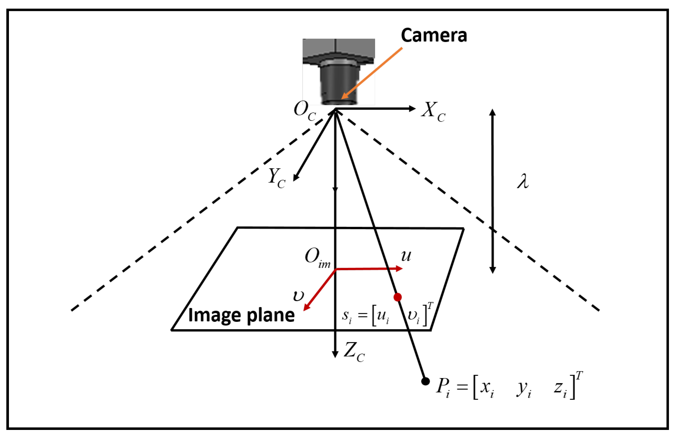
Herein, the mathematical formulation of the image based visual servoing problem is presented. We consider a camera with a frame { C } attached at its center O c and [ X c , Y c , Z c ] the camera frame axes. The image frame { I m } coordinates, as shown in Figure 2, are decribed by [ u , v ] with O i m being the image center [39].
According to the camera geometrical model, a set of n fixed 3D points p i = [ x i , y i , z i ] T , i = 1 , , n expressed w.r.t the camera frame, are actually projected to the 2D image plane as s i = [ u i , v i ] T , i = 1 , , n in pixels, via the following equation [40]:
s i = u i v i = λ z i x i y i
with λ denoting the focal length of the camera. The time derivative of the image features is related to the camera velocity as follows:
s ˙ i = L i ( z i , s i ) v c , i = 1 , , n
where:
L i z i , s i = λ z i 0 u i z i u i v i λ λ 2 + u i 2 λ v i 0 λ z i v i z i λ 2 + v i 2 λ u i v i λ u i
is the interaction matrix [40], and v c t c T , ω c T T contains the linear t c and rotational ω c velocities of the camera frame. Next, we define as s = s 1 T , , s n T T 2 n the overall image feature vector. Hence, the time-derivative of the image features is given by:
s ˙ = L ( z , s ) v c
where L z , s = L 1 T z 1 , s 1 , , L n T z n , s n T 2 n × 6 is the interaction matrix including all the available features and z = z 1 , , z n T their respective depths. Inevitably, visibility constraints are imposed by the limited camera field of view, via the following inequalities:
u min u i u max , i = 1 , , n
v min v i v max , i = 1 , , n
where u min , v min and u max , v max describe the lower and upper bounds (in pixels) of the image coordinates as dictated by the camera resolution ( width × height ). The task of retaining the features of interest inside the camera field of view is of utmost importance in IBVS control of mobile manipulators, since otherwise not only the mission is compromised, e.g., object grasping or target tracking, but also unpredicted motions that may harm the system may occur due to the loss of visual feedback in the control loop.

2.3. Problem Statement

Let s d = s 1 d , , s n d 2 n denote the vector of desired image features. The objective is to control the Floating Base Mobile Manipulator System subject to the visibility and system’s operational constraints in such a way that the actual image features s ( t ) converge to a desired compact set that includes the desired image features vector s d . Hence, the problem of this paper is defined as follows:
Problem 1.
Given a Floating Base Mobile Manipulator System equipped with a camera at its end effector and a desired image features vector s d that corresponds to a desired configuration of the camera with respect to the object, design a robust feedback control protocol, without considering any knowledge of either the system dynamics, or the exogenous disturbances, so that the following are satisfied:
  • The image features do not escape the image plane during the control operation (field of view constraints);
  • Predetermined overshoot, rate of convergence and steady state error for the image features and the system velocities;
  • Respect system’s operational limitations, e.g., manipulator joint limits, system’s manipulability;
  • Robustness against exogenous disturbances, system model uncertainties, camera calibration and depth estimation errors.

3. Control Methodology

In this work, regarding the 2 D control of image features in the image plane, we adopt the Prescribed Performance Image Based Visual Servoing (PP-IBVS), presented in our previous work [27,28] to achieve prescribed transient as well as steady state response for all image feature errors while respecting the FoV constraints (7a,b). It should be highlighted that the PP-IBVS scheme exhibits proven robustness with respect to camera calibration and depth estimation errors. Moreover, in a similar way, regarding the system control at the dynamic level, we adopt the prescribed performance control technique [41,42,43] in order to attain prescribed performance for the system velocity errors.
The overall control architecture is depicted in Figure 3. As it can be seen, a cascaded control approach is employed, where the PP-IBVS acts as input for the PPC velocity controller, which yields the required actuation forces and torques without the need of a dynamic model. More specifically, a vision algorithm is responsible for detecting the position of features s ( t ) in the image plane, while the desired feature positions s d are defined by the user (e.g., using a reference image). The formulated image error is fed to the PP-IBVS scheme which is responsible for calculating the desired velocities for each DoF of the overall system, in such a manner where the image errors and their transient response are prescribed, while simultaneously the field of view constraints are satisfied (i.e., the target is always visible from the camera). Next, the PPC scheme realizes the aforementioned velocities by calculating the appropriate forces and torques for the actuators of the robotic system, while achieving prescribed performance for the velocity errors and their transient responses and simultaneously satisfying actuation (e.g., joint motors) limits.
In a real system, the joint velocities can be measured by the encoders of the manipulator, while the vehicle velocities can be estimated on-line by fusing data from the appropriate navigation sensors. Since in our work we consider a UVMS as a test-bed, the vehicle’s velocities could be obtained by the fusion of Doppler Velocity Log (DVL) and Inertial Measurement Unit (IMU) measurements, e.g., via an Extended Kalman Filter (EKF). In the presented simulation scenarios, the required system velocities are available by the realistic ROS-based simulation framework UwSim [44].

3.1. PP-IBVS Control Design

At first, we define the image feature errors as:
e i u ( t ) = u i ( t ) u i d , i = 1 , , n
e i v ( t ) = v i ( t ) v i d , i = 1 , , n
where u i d , v i d are the desired image features and e e 1 u , e 1 v , , e n u , e n v T denotes the overall error. By employing the prescribed performance notion, we aim at imposing a strict evolution of the image feature errors within predefined and bounded regions, inside the image space. These regions are defined by appropriately selected strictly positive and decreasing performance functions of time. According to the prescribed performance control methodology we define the following inequalities for all t 0 :
M ̲ i u ρ i u ( t ) < e i u ( t ) < M ¯ i u ρ i u ( t ) , i = 1 , , n
M ̲ i v ρ i v ( t ) < e i v ( t ) < M ¯ i v ρ i v ( t ) , i = 1 , , n
where
ρ i u ( t ) = 1 ρ max M ̲ i u , M ¯ i u exp ( l t ) + ρ max M ̲ i u , M ¯ i u
ρ i v ( t ) = 1 ρ max M ̲ i v , M ¯ i v exp ( l t ) + ρ max M ̲ i v , M ¯ i v
are designer-specified smooth, bounded and decreasing functions of time with l, ρ > 0 incorporating the desired transient and steady state performance specifications, respectively, and M ̲ i u , M ¯ i u , M ̲ i v , M ¯ i v are positive parameters appropriately selected to satisfy the visibility constraints (7a,b). In particular, the decreasing rate of ρ i u ( t ) , ρ i v ( t ) , which is regulated by the parameter l, introduces a lower bound on the speed of convergence of e i u ( t ) , e i v ( t ) , i = 1 , , n . Depending on the accuracy of the vision detection algorithm, the parameter ρ can be set arbitrarily small ρ < < min i = 1 , , n { M ̲ i u , M ¯ i u , M ̲ i v , M ¯ i v } , in order to achieve convergence of e i u ( t ) , e i v ( t ) , i = 1 , , n close to zero. Moreover, we select:
M ̲ i u = u i d u min & M ¯ i u = u max u i d , i = 1 , , n
M ̲ i v = v i d v min & M ¯ i v = v max v i d , i = 1 , , n
Under the logical assumption that the features are initially located inside the camera field of view (i.e., u min < u i ( 0 ) < u max and v min < v i ( 0 ) < v max , i = 1 , , n ) it is guaranteed that:
M ̲ i u ρ i u ( 0 ) < e i u ( 0 ) < M ¯ i u ρ i u ( 0 ) , i = 1 , , n
M ̲ i v ρ i v ( 0 ) < e i v ( 0 ) < M ¯ i v ρ i v ( 0 ) , i = 1 , , n
Hence, employing the decreasing property of ρ i u ( t ) , ρ i v ( t ) , i = 1 , , n and invoking (9a,b) for all t > 0 , we achieve:
M ̲ i u < e i u ( t ) < M ¯ i u , i = 1 , , n
M ̲ i v < e i v ( t ) < M ¯ i v , i = 1 , , n
which owing to (8a,b) and (11a,b), yields:
u min < u i ( t ) < u max , i = 1 , , n
v min < v i ( t ) < v max , i = 1 , , n
for all t > 0 , thus respecting the visibility constraints as required by Section 2.3.
Next, we proceed to the design of a state feedback control scheme without incorporating any knowledge regarding the system dynamic model (2). The proposed scheme will be robust against inaccurate depth measurements and camera parameters, and will also guarantee via (9a,b) for all t 0 , prescribed performance under visibility constraints for the given IBVS problem. The overall control architecture is illustrated in Figure 3. More specifically, initially, we define the normalized image feature errors as:
ξ i u ( u i , t ) = e i u ρ i u ( t ) & ξ i v ( v i , t ) = e i v ρ i v ( t ) , i = 1 , , n
and the transformed image feature errors as:
E i u ξ i u ( u i , t ) = ln 1 + ξ i u ( u i , t ) M ̲ i u 1 ξ i u ( u i , t ) M ¯ i u & E i v ξ i v ( v i , t ) = ln 1 + ξ i v ( v i , t ) M ̲ i v 1 ξ i v ( v i , t ) M ¯ i v
for which e i u 0 ( e i v 0 ) implies E i u 0 ( E i v 0 ), i = 1 , , n . Finally, the IBVS controller is formulated as:
v c r ( s , t ) = k L ^ + E ( s , t ) , k > 0
with L ^ + L ^ L ^ 1 L ^ being the Moore-Penrose pseudo-inverse of the estimated interaction matrix [45], expressed in the regular image space, and
E ( s , t ) E 1 u , E 1 v , , E n u , E n v .

3.2. Handling of Operational Specifications and Limits

The frame { C } of the camera that is rigidly attached on the End-Effector at O C does not necessarily coincide with the End-Effector frame { E } . Therefore, considering a spatial motion transformation matrix e V c 6 × 6 , the PP-IBVS given in (17) can be transformed from the camera frame to the End-Effector frame via [15]:
v e r ( s , t ) = e V c v c r ( s , t )
Moreover, the End-Effector desired motion profile v e r ( s , t ) is transformed to the configuration space as follows:
ζ r ( t ) = J ( q ) # v e r + I n × n J ( q ) # J q v e 0 n
where J ( q ) # denotes the generalized pseudo-inverse [46] of the Jacobian J ( q ) of the vehicle-manipulator system and v e 0 denotes secondary tasks, in order to satisfy vital system’s operational limitations (e.g., manipulator’s joint limits, manipulability) to be tuned independently since they do not affect the end-effector’s velocity [47] (i.e., they belong to the null space of the Jacobian J ( q ) ). In the proposed work, image feature error minimization and field of view constraints are identified as primary tasks handled by the first part (i.e., J ( q ) # v e r ) of (20), while the secondary tasks such as manipulator joint limits, avoiding kinematic singularity representations as well as system manipulability are incorporated in v e 0 and handled by the second part (i.e., I n × n J ( q ) # J q v e 0 ) of (20) in a fully decoupled manner. More details on task priority based control for FBMMSs can be found in [47,48].

3.3. Prescribed Performance Velocity Control

Given the desired configuration space motion profile ζ r ( t ) in (20) that satisfies different operational limitations, we proceed with the design of a model-free velocity controller that does not incorporate any information regarding the system’s dynamics, or exogenous disturbances, and achieves certain predefined transient and steady state response. Similarly to the PP-IBVS, the first step is to define the velocity error vector:
e ζ ( t ) [ e ζ 1 ( t ) , , e ζ n r ( t ) ] = ζ ( t ) ζ r ( t ) n r
and then select the corresponding performance functions:
ρ ζ i ( t ) = ( ρ ζ i 0 ρ ζ i ) exp ( l ζ i t ) + ρ ζ i , i = 1 , , n r
with ρ ζ i 0 > | e ζ i ( 0 ) | , ρ ζ i > 0 and l ζ i > 0 , i = 1 , n r . Notice that similarly to the image features’ errors we aim to impose transient and steady state response on the system velocities errors e ζ i ( t ) , i = 1 , , n r as well, by satisfying:
ρ ζ i ( t ) < e ζ i ( t ) < ρ ζ i ( t ) , t 0 i = 1 , , n r
Next, the transformed velocity error vector is defined as:
ε ζ ( ξ ζ ) [ ε ζ 1 ( ξ ζ 1 ) , , ε ζ n r ( ξ ζ n r ) ] = [ ln ( 1 + ξ ζ 1 1 ξ ζ 1 ) , , ln ( 1 + ξ ζ n r 1 ξ ζ n r ) ]
where
ξ ζ ( t ) [ ξ ζ 1 , , ξ ζ n r ] = P ζ 1 ( t ) e ζ ( t )
is the normalized velocity error vector, with P ζ ( t ) = diag i = 1 , , n r [ ρ ζ i ( t ) ] and we design the state feedback control law:
τ ( e ζ ( t ) , t ) = K ζ P ζ 1 ( t ) R ζ ( ξ ζ ) ε ζ ( ξ ζ )
where
R ζ ( ξ ζ ) = diag i = 1 , , n r 2 1 ξ ζ i 2
and K ζ > 0 is a diagonal gain matrix.
Remark 2.
The error transformation (visual errors for PP-IBVS and velocity errors in PPC velocity control) is realized in order to transform a constrained nominal dynamic system to an equivalent unconstrained one whose stability is sufficient to achieve the tracking control of the original constrained system with a priori prescribed performance.

4. Stability Analysis

In this section, we prove analytically that the proposed control architecture deals successfully with the IBVS problem for floating base mobile manipulator systems with prescribed performance under operational constraints.
Theorem 1.
Consider n 4 fixed visual features in the workspace and a pinhole camera mounted on the end-effector of a floating base manipulator system with n r 6 DoFs that aims at achieving the desired positions for the feature coordinates on the image plane, while respecting the field of view constraints as well as operational limitations in the form of manipulator joint limits and manipulability. Assuming that all visual features initially lie sufficiently close to their desired values as well as within the field of view of the camera, the proposed IBVS architecture comprising of (17), (19), (20) and (26) guarantees local practically asymptotic stabilization of the feature errors.
Proof. 
First, let us define the overall normalized error vector ξ = [ ξ s , ξ ζ ] with ξ s = [ ξ 1 u , ξ 1 v , , ξ n u , ξ n v ] . Differentiating (15) and (25) with respect to time and substituting the system dynamics (2), (6), (21), (19) and (26), we obtain the closed loop system dynamics:
ξ ˙ s h s ( ξ s , t )
ξ ˙ ζ ( ξ ζ , t ) h ζ ( ξ ζ , t )
which can be written in compact form as:
ξ ˙ h ( ξ , t ) = [ h s ( ξ s , t ) , h ζ ( ξ ζ , t ) ]
Let us define the open set Ω ξ = Ω ξ s × Ω ξ ζ with Ω ξ s ( M ̲ 1 u , M ¯ 1 u ) × ( M ̲ 1 v , M ¯ 1 v ) × × ( M ̲ n u , M ¯ n u ) × ( M ̲ n v , M ¯ n v ) and Ω ξ ζ ( 1 , 1 ) n r . In what follows, we proceed in two phases. First we ensure the existence of a unique maximal solution ξ ( t ) of (29) over the set Ω ξ for a time interval [ 0 , t max ) (i.e., ξ ( t ) Ω ξ , t [ 0 , t max ) ). Then, we prove that the proposed control protocol guarantees, for all t [ 0 , t max ) the boundedness of all closed loop signals as well as that ξ ( t ) remains strictly within the set Ω ξ , which leads by contradiction to t max = and consequently to the satisfaction of (9a,b) and (23), thus completing the proof.
Phase A: The set Ω ξ is nonempty and open. Moreover (12a,b) and (23) leads to M ̲ i u < ξ i u ( 0 ) < M ¯ i u , i { u 1 , u n } , M ̲ i v < ξ i v ( 0 ) < M ¯ i v , i { v 1 , v n } and 1 < ξ ζ i ( 0 ) < 1 , i = 1 , , n r . Thus, we guarantee that ξ s ( 0 ) Ω ξ s and ξ ζ ( 0 ) Ω ξ ζ . Additionally, h ( ξ , t ) , as defined in (29), is continuous on t and locally Lipschitz on ξ over Ω ξ . Therefore, the hypotheses of the Theorem 54 in [49] (p. 476) hold and the existence of a maximal solution ξ ( t ) of (29) on a time interval [ 0 , t max ) such that ξ ( t ) Ω ξ , t [ 0 , t max ) is ensured.
Phase B: In Phase A, we proved that ξ ( t ) Ω ξ , t [ 0 , t max ) , thus it can be concluded that:
ξ i u ( t ) = e i u ( t ) ρ i u ( t ) ( M ̲ i u , M ¯ i u ) , i { 1 , , n }
ξ i v ( t ) = e i v ( t ) ρ i v ( t ) ( M ̲ i v , M ¯ i v ) , i { 1 , , n }
ξ ζ i ( t ) = e ζ i ( t ) ρ ζ i ( t ) ( 1 , 1 ) , i { 1 , , n r }
for all t [ 0 , t max ) , from which we obtain that e i u ( t ) , e i v ( t ) and e ζ i ( t ) are lower and upper bounded by M ̲ i u ρ i u ( t ) , M ¯ i u ρ i u ( t ) , M ̲ i v ρ i v ( t ) , M ¯ i v ρ i v ( t ) and ρ ζ i ( t ) , ρ ζ i ( t ) , respectively. Therefore, the transformed error vectors E i u ξ i u ( u i , t ) , E i v ξ i v ( v i , t ) and ε ζ i ( ξ ζ i ) designated in (16) and (24), respectively, are well-defined for all t [ 0 , t max ) . Hence, consider the positive definite and radially unbounded function:
V ( E ) = 1 2 E ( ξ s ) E ( ξ s )
Differentiating V ( E ) with respect to time, substituting (28a) and considering u i ˙ d ( t ) , v i ˙ d ( t ) , ρ i u ( t ) , ρ i v ( t ) i { 1 n } and ρ ζ i ( t ) , i = 1 , , n r are bounded by construction and ξ i u , ξ i v , ξ ζ i are also bounded within the compact sets Ω ξ s and Ω ξ ζ owing to (30a–c), we conclude the existence of a position constant ε ¯ s such that:
| E ( ξ s ( t ) ) | ε ¯ s , t [ 0 , t max )
Furthermore, from (18), and invoking the inverse logarithmic function, we obtain:
M ̲ i u < ξ ̲ i u ξ i u ( t ) ξ ¯ i u < M ¯ i u , t [ 0 , t max ) , i { 1 n }
M ̲ i v < ξ ̲ i v ξ i v ( t ) ξ ¯ i v < M ¯ i v , t [ 0 , t max ) , i { 1 n }
where:
ξ ̲ i u = M ̲ i u exp ( ε ¯ s ) 1 exp ( ε ¯ s ) + M ̲ i u M ¯ i u , ξ ¯ i u = M ¯ i u exp ( ε ¯ s ) 1 exp ( ε ¯ s ) + M ¯ i u M ̲ i u
ξ ̲ i v = M ̲ i v exp ( ε ¯ s ) 1 exp ( ε ¯ s ) + M ̲ i v M ¯ i v , ξ ¯ i v = M ¯ i v exp ( ε ¯ s ) 1 exp ( ε ¯ s ) + M ¯ i v M ̲ i v
Owing to (33a,b) and (20) it can concluded that the reference velocity vector ζ r remains bounded for all t [ 0 , t max ) as well. Moreover, invoking ζ = ζ r ( t ) + P ζ ( t ) ξ ζ from (25), we also conclude the boundedness of ζ for all t [ 0 , t max ) . Finally, differentiating ζ r ( t ) w.r.t time and employing (28a,b), (30a–c) and (33a,b) we conclude the boundedness of ζ ˙ r ( t ) , t [ 0 , t max ) too.
Now let us consider the positive definite and radially unbounded function V ζ ( ε ζ ) = 1 2 | | ε ζ | | 2 . Differentiating V ζ with respect to time, substituting (28b) and employing the continuity of M , C , D , g , δ , ξ ζ , P ˙ ζ , ζ ˙ r , t [ 0 , t max ) , we obtain:
V ˙ ζ | | P ζ 1 R ζ ( ξ ζ ) ε ζ | | B ζ λ M K ζ | | P ζ 1 R ζ ( ξ ζ ) ε ζ | |
t [ 0 , t max ) , where λ M is the minimum eigenvalue of the positive definite matrix M 1 and B ζ is a positive constant independent of t max , that satisfies:
B ζ | | M 1 ( C · ( P ζ ξ ζ + ζ r ( t ) ) + D · ( P ζ ξ ζ + ζ r ( t ) ) + g + δ ( t ) + P ˙ ζ ξ ζ + ζ ˙ r ) | |
Thus, we conclude that:
| | ε ζ ( ξ ζ ) | | ε ¯ ζ , t [ 0 , t max )
Furthermore, from (27) and invoking | ε ζ i | ε ¯ ζ , we obtain:
1 < ξ ̲ ζ i ξ ζ i ( t ) ξ ¯ ζ i < 1 , t [ 0 , t max ) , i = 1 , , n r
where
ξ ̲ ζ i = exp ( ε ¯ ζ ) 1 exp ( ε ¯ ζ ) + 1 , ξ ¯ ζ i = exp ( ε ¯ ζ ) 1 exp ( ε ¯ ζ ) + 1
which also leads to the boundedness of the control law (26) for all t [ 0 , t max ) .
Subsequently, we will show that t max can be extended to infinity. Obviously, notice by (33a,b) and (37) that ξ ( t ) Ω ξ Ω ξ s × Ω ξ ζ , t [ 0 , t max ) , where:
Ω ξ s = [ ξ ̲ 1 u , ξ ¯ 1 u ] × [ ξ ̲ 1 v , ξ ¯ 1 v ] × [ ξ ̲ n u , ξ ¯ n u ] × [ ξ ̲ n v , ξ ¯ n v ] Ω ξ ζ = [ ξ ̲ ζ 1 , ξ ¯ ζ 1 ] × × [ ξ ̲ ζ n r , ξ ¯ ζ n r ] ,
are nonempty and compact subsets of Ω ξ s and Ω ξ ζ , respectively. Hence, assuming that t max < and since Ω ξ Ω ξ , Proposition C.3.6 in [49] (p. 481) dictates the existence of a time instant t [ 0 , t max ) such that ξ ( t ) Ω ξ , which is a clear contradiction. Therefore, t max = . Thus, all closed loop signals remain bounded and moreover ξ ( t ) Ω ξ , t 0 . Finally, from (30a–c) and (33a,b), we conclude that:
M ̲ u i ρ i u ( t ) < M ̲ u i exp ( ε ¯ s ) 1 exp ( ε ¯ s ) + M ̲ u i M ¯ u i ρ i u ( t ) e i u ( t ) M ¯ u i exp ( ε ¯ s ) 1 exp ( ε ¯ s ) + M ¯ u i M ̲ u i ρ i u ( t ) < M ¯ u i ρ i u ( t )
M ̲ v i ρ i v ( t ) < M ̲ v i exp ( ε ¯ s ) 1 exp ( ε ¯ s ) + M ̲ v i M ¯ v i ρ i v ( t ) e i v ( t ) M ¯ v i exp ( ε ¯ s ) 1 exp ( ε ¯ s ) + M ¯ v i M ̲ v i ρ i v ( t ) < M ¯ v i ρ i v ( t )
for all t 0 , which completes the proof. □

5. Simulation Results

5.1. System Components and Parameters

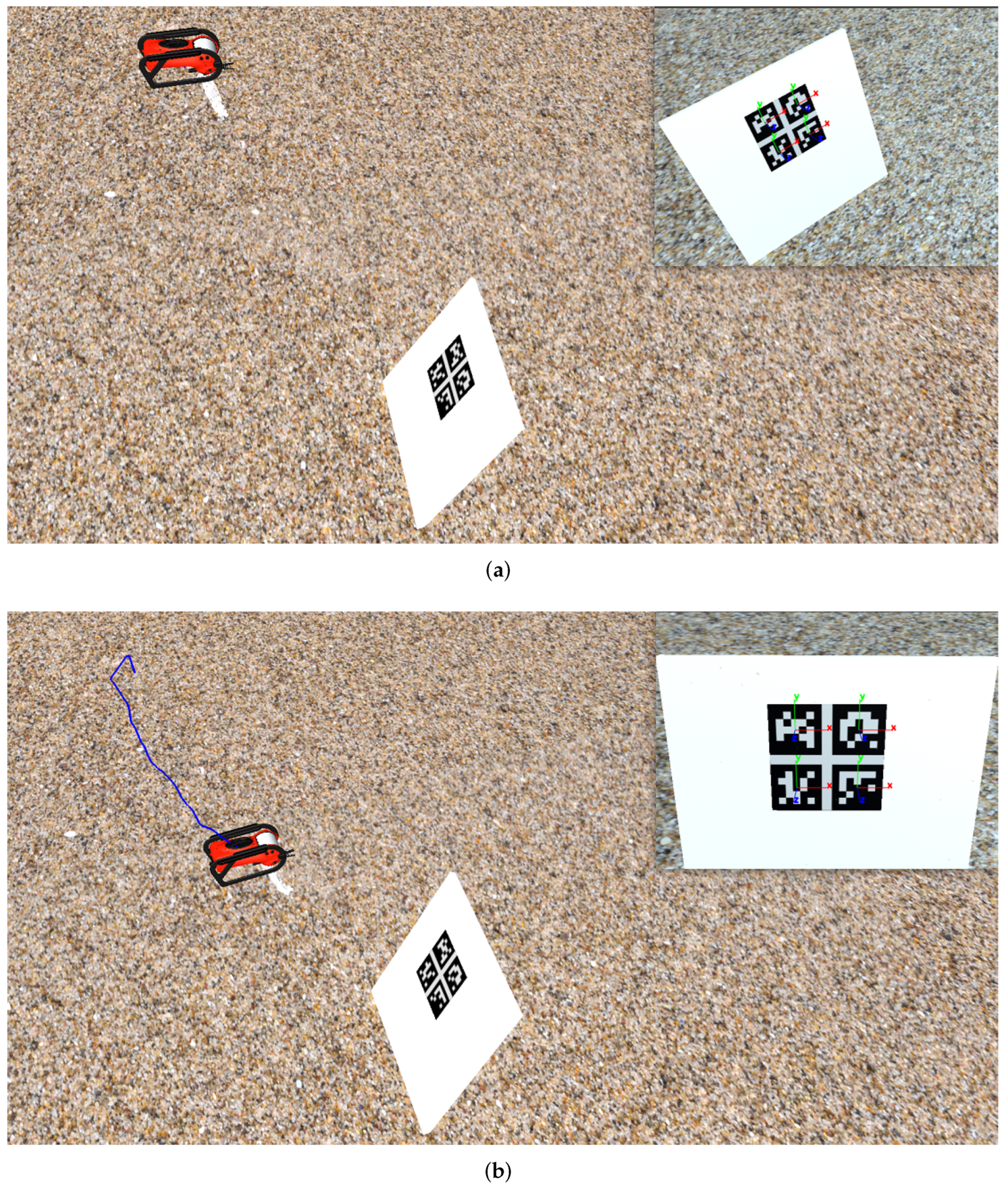
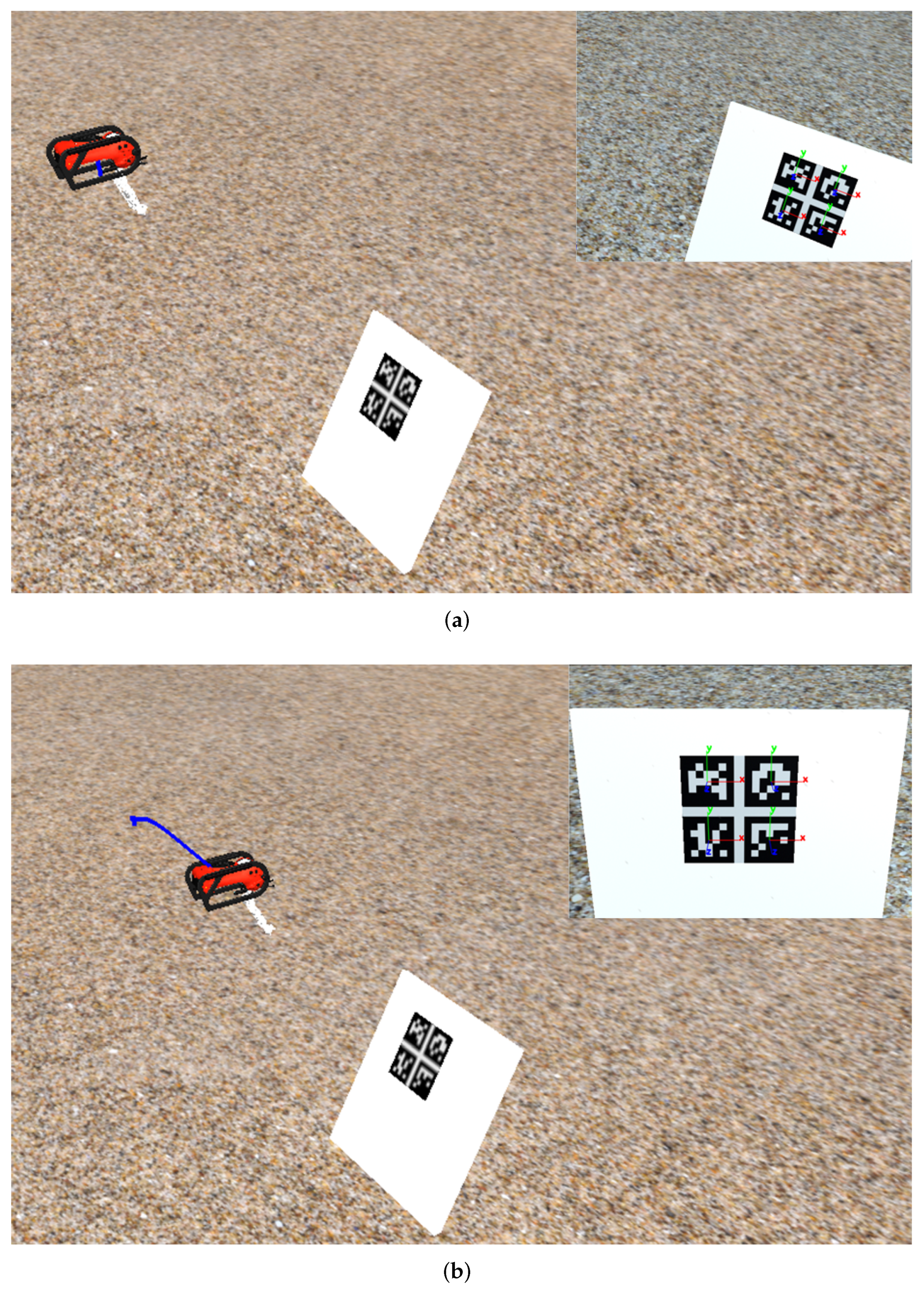
In order to verify the proposed IBVS approach for FBMMSs, two realistic simulation scenarios were performed. An Underwater Vehicle Manipulator System (UVMS) is considered as candidate FBMMS platform. It is worth mentioning that the highly nonlinear dynamics of such systems are heavily affected by the almost unknown undersea water dynamics. Therefore, due to the large dynamic uncertainties, they constitute an ideal test-bed verifying the proposed control strategy. The simulation environment is implemented using the UwSim dynamic simulator [44] running on the Robot Operating System (ROS) [50], and the source code is written in C++ and Python. In particular, we consider two scenarios involving a UVMS consisting of an underwater vehicle with 4 DoFs (Surge, Sway, Heave Yaw) and a 4 rotational DoFs manipulator system attached to the underside of the vehicle. A camera with 640 × 480 pixels at 30 frames per second (fps) is mounted on the manipulator’s end-effector. In each of the two simulations the UVMS is located at an initial configuration so that it is able to observe a visual target located at the bottom of the sea (see Figure 4 and Figure 5). The target is located at a fixed configuration inside the workspace and consists of four markers. Each marker center denotes an image feature that is detected using the Computer Vision ArToolkit library [51] and its ROS implementation. The loop rate of the PP-IBVS contoller was set at 0.03   s , while the loop rate of the PPC velocity controller was set at 0.02   s . It is worth mentioning that the considered initial pose for each of the two scenarios (Figure 4 and Figure 5) is rather challenging for IBVS schemes, due to the significant rotation about the x axis of the camera frame as well as the large distance relative to the target configuration. The desired feature coordinates s d = 251 379 251 379 196 196 318 318 were the same for both scenarios and extracted by a still image captured at the desired pose of the camera.

5.2. Results

In the following simulation studies, the objective for the proposed IBVS control scheme is to to autonomously guide the system from the initial configuration to the desired s d . Moreover, the proposed controller should simultaneously satisfy: (i) the visibility constraints i.e., keep the object inside the field of view of the camera (ii) operational limitations i.e., manipulator joint limits, as well as (iii) predefined transient and steady-state performance specifications both on image features and system velocities errors.

5.2.1. Scenario 1

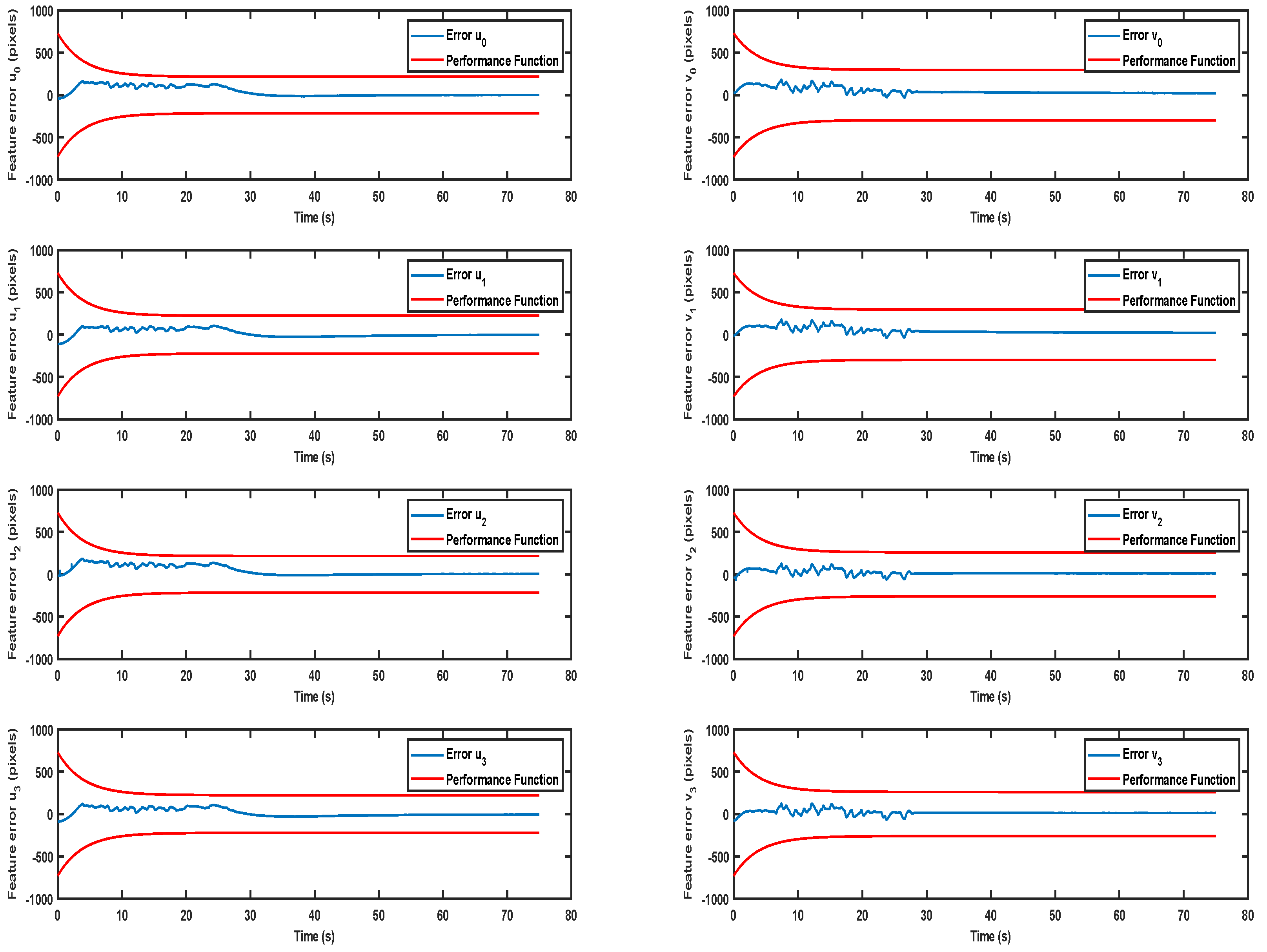
In the first scenario, the UVMS is initialized at the configuration depicted in Figure 4a. More specifically, the vehicle was located at [ x υ , y υ , z υ , ψ υ ] = [ 0.63 , 2.37 , 1.78 , 1.57 ] and the manipulator’s joints were configured at [ q m 1 , q m 2 , q m 3 , q m 4 ] = [ 0.6 , 0.25 , 0.25 , 0.0 ] , which led to a very difficult initial configuration for an IBVS scheme, s s 1 0 = 205 264 234 290 207 176 273 238 , where the target is very close to the image boundaries and can easily escape from the camera field of view. The parameters of the performance functions for the PP-IBVS scheme were set at ρ = 100 and λ = 0.25 , while the values of M ̲ i u , M ¯ i u , M ̲ i v , M ¯ i v , i = 1 4 were formulated according to the values of s d and the image boundaries dictated by the camera analysis ( 640 × 480 ). The evolution of image features errors is depicted in Figure 6. As it can be easily observed, the feature coordinate errors were retained within the corresponding performance envelopes and consequently the visibility constraints were continuously satisfied. The system was successfully guided to the desired configuration as depicted in Figure 4b.
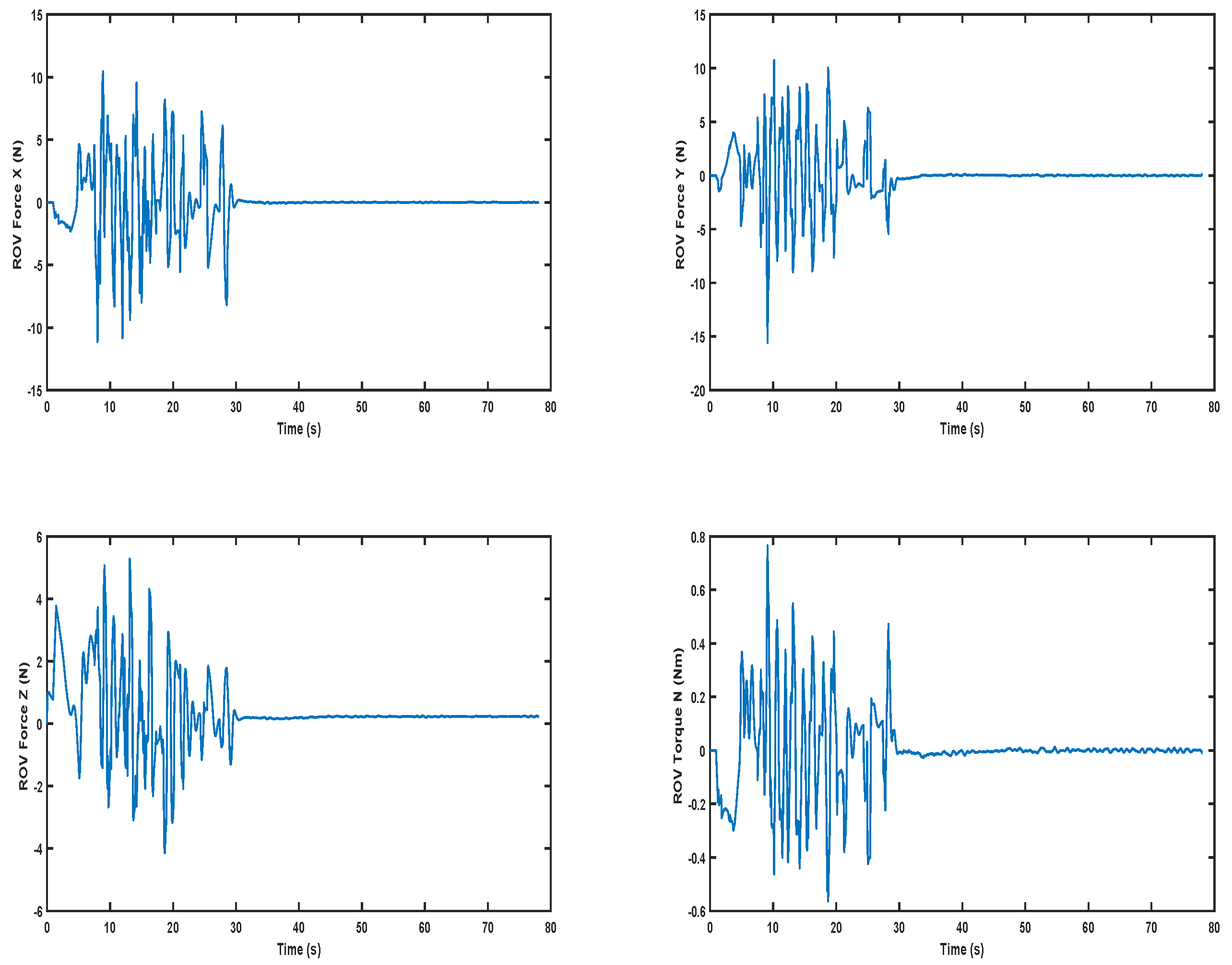
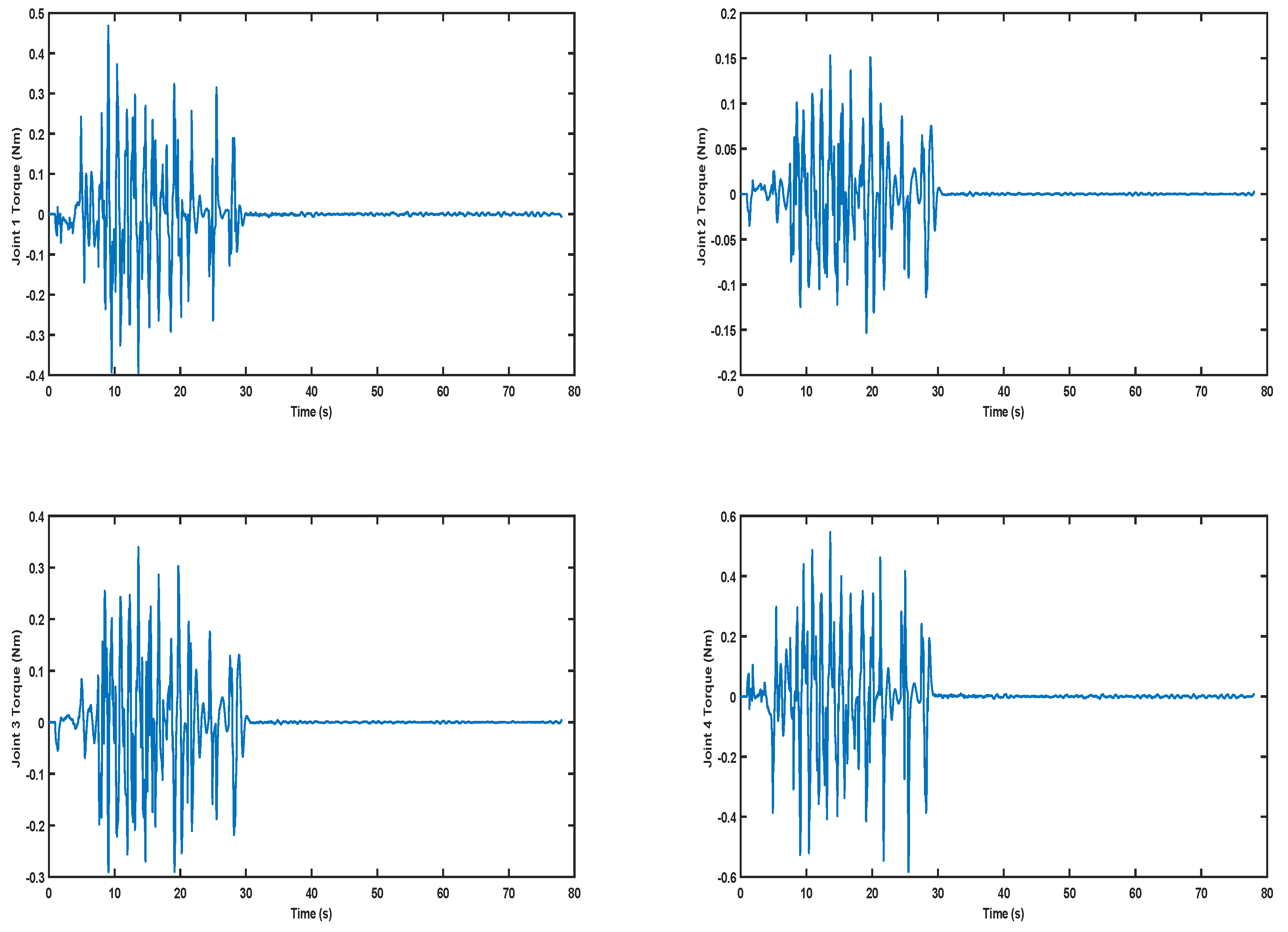
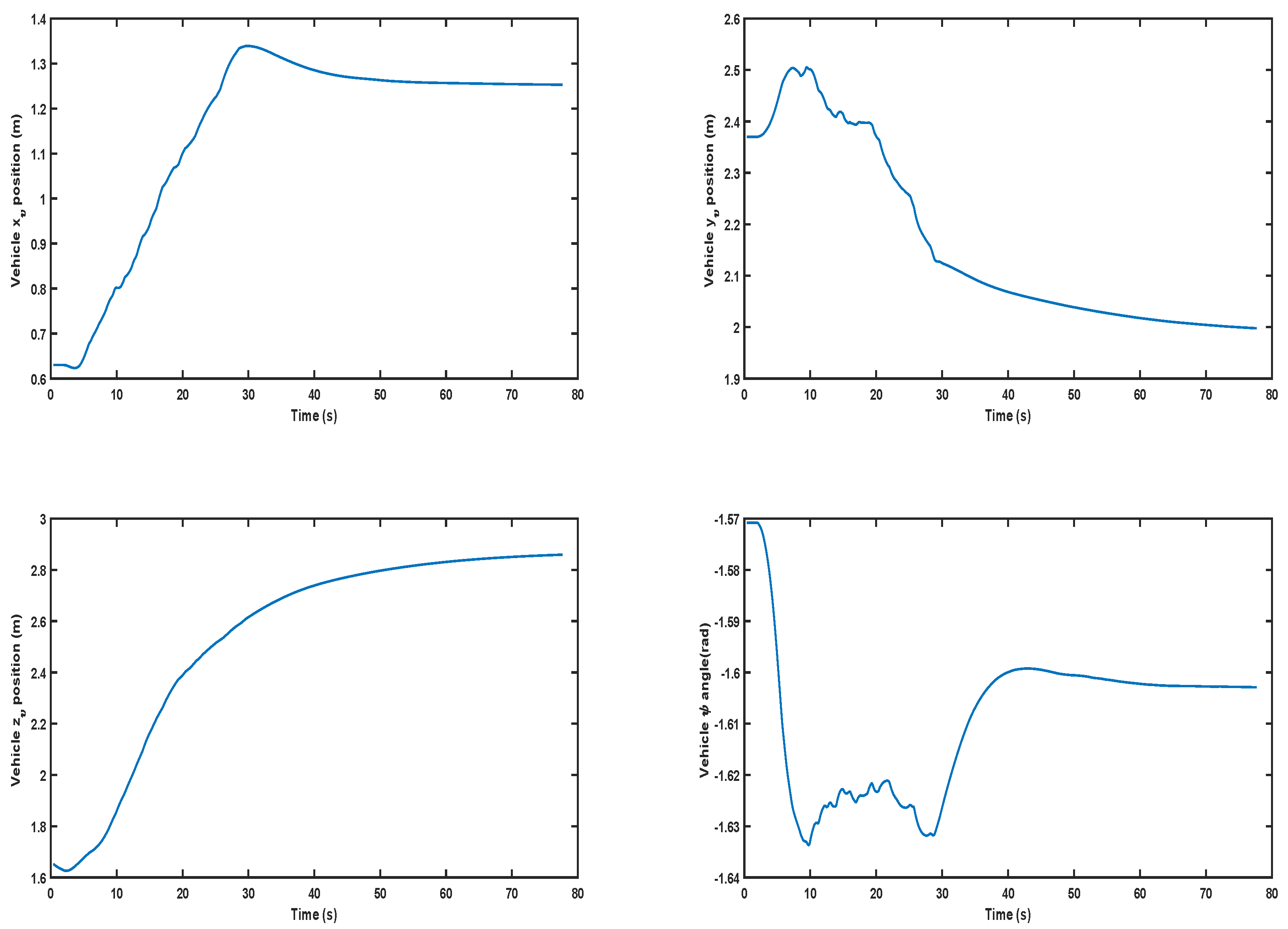
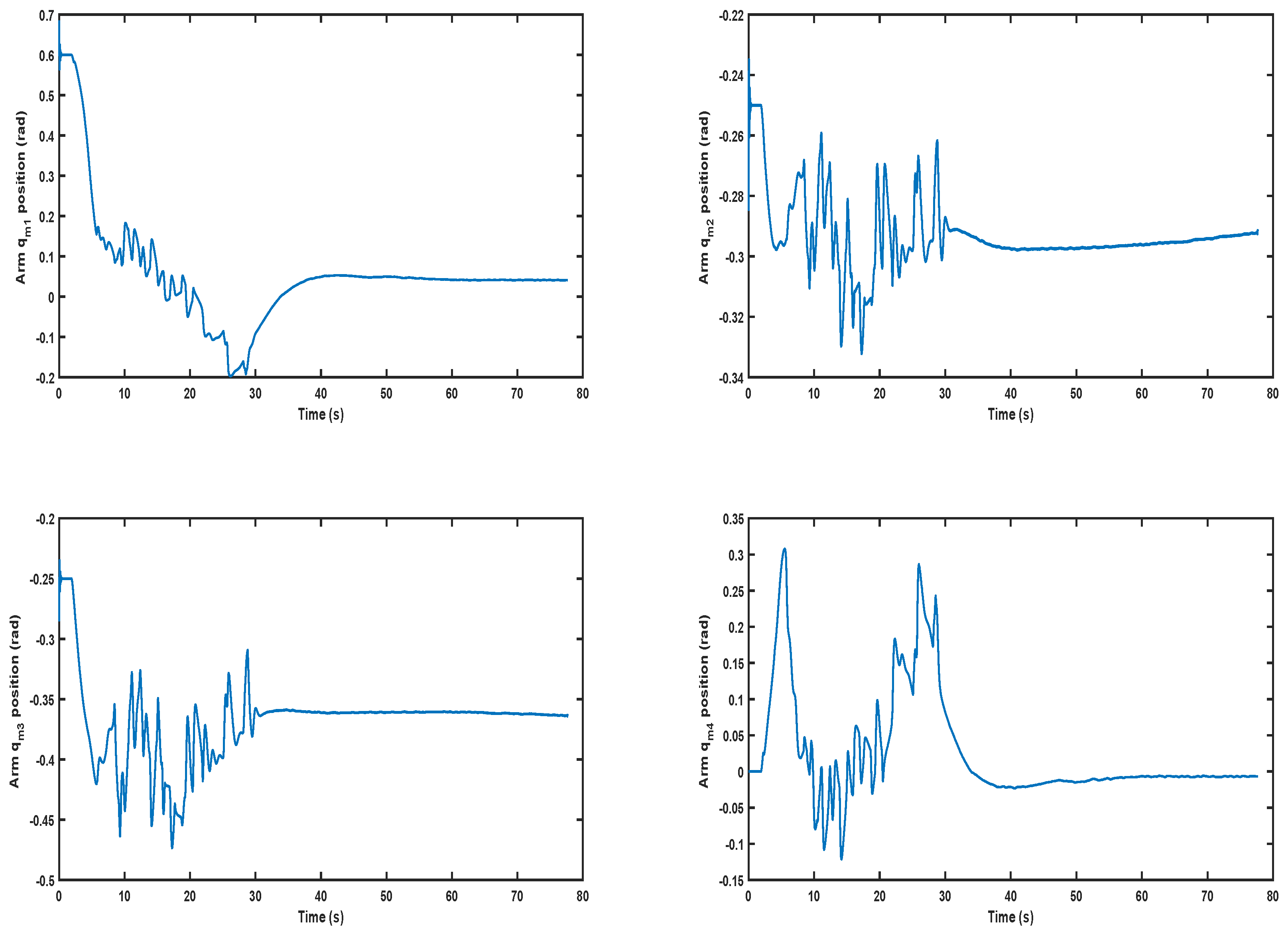
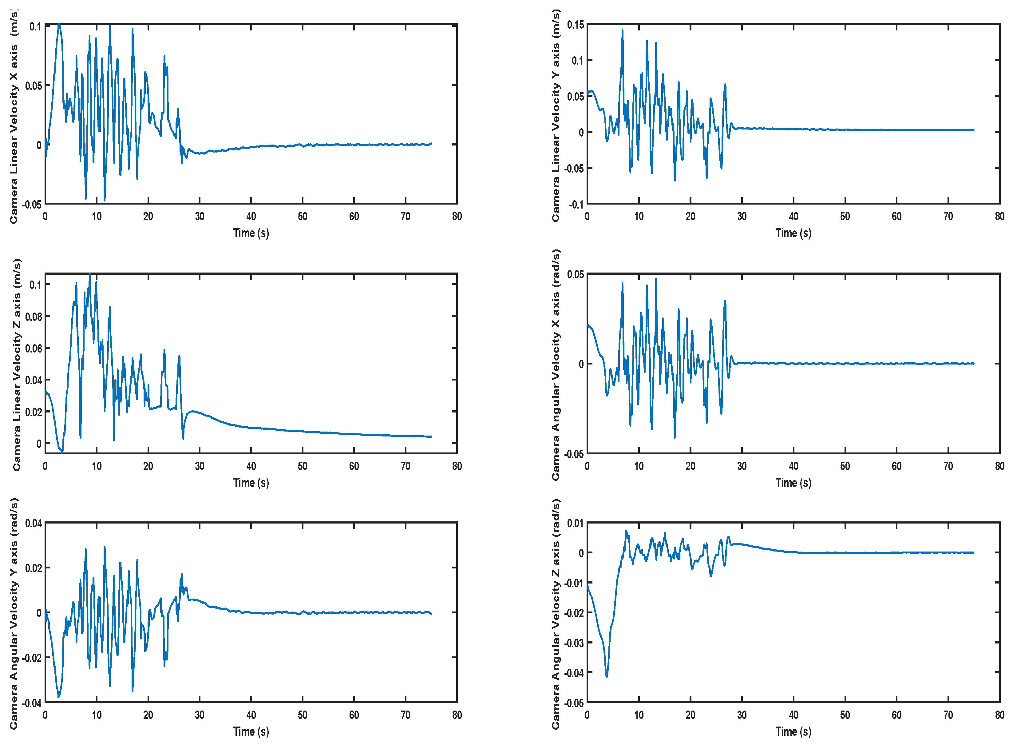
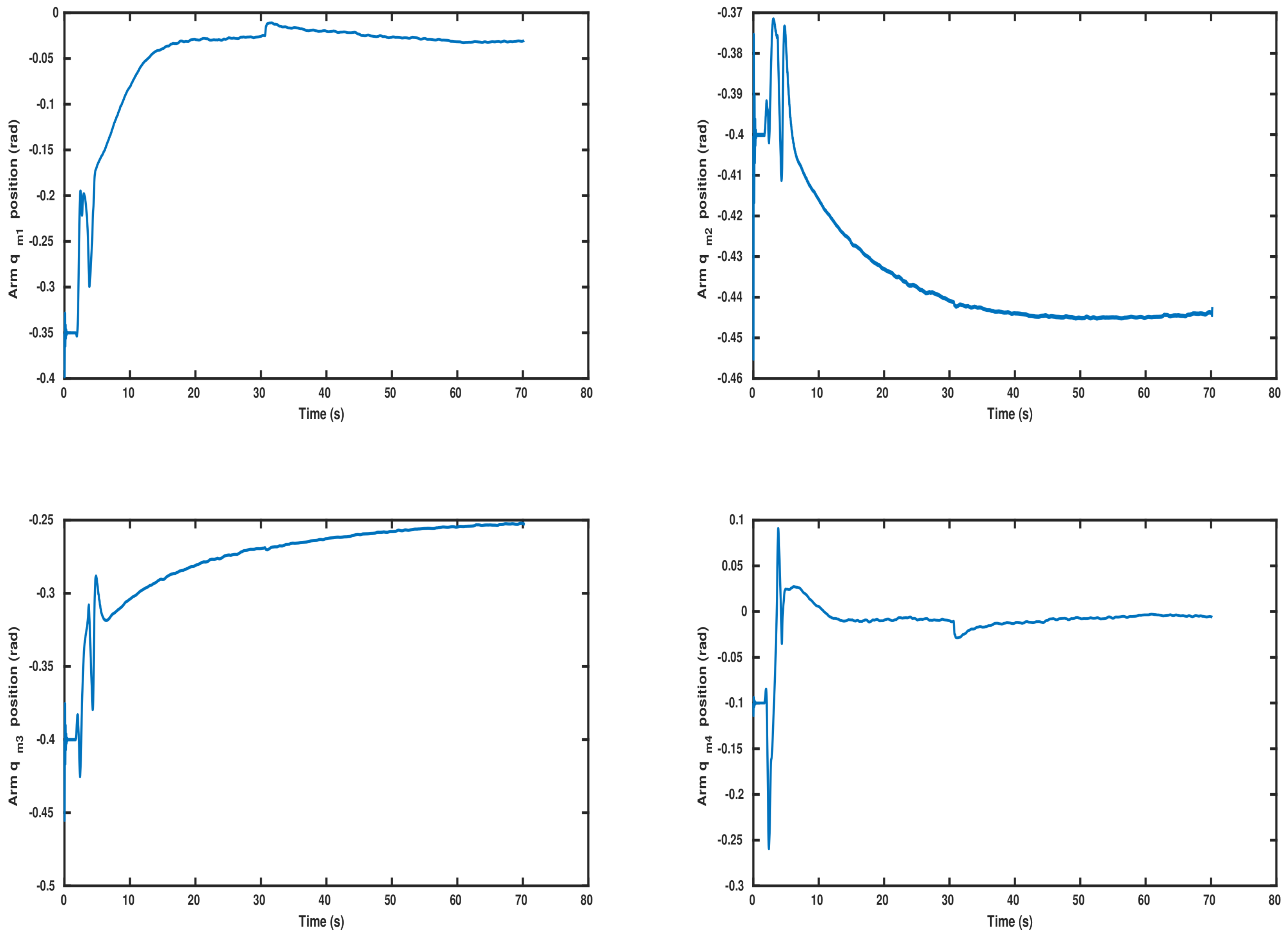
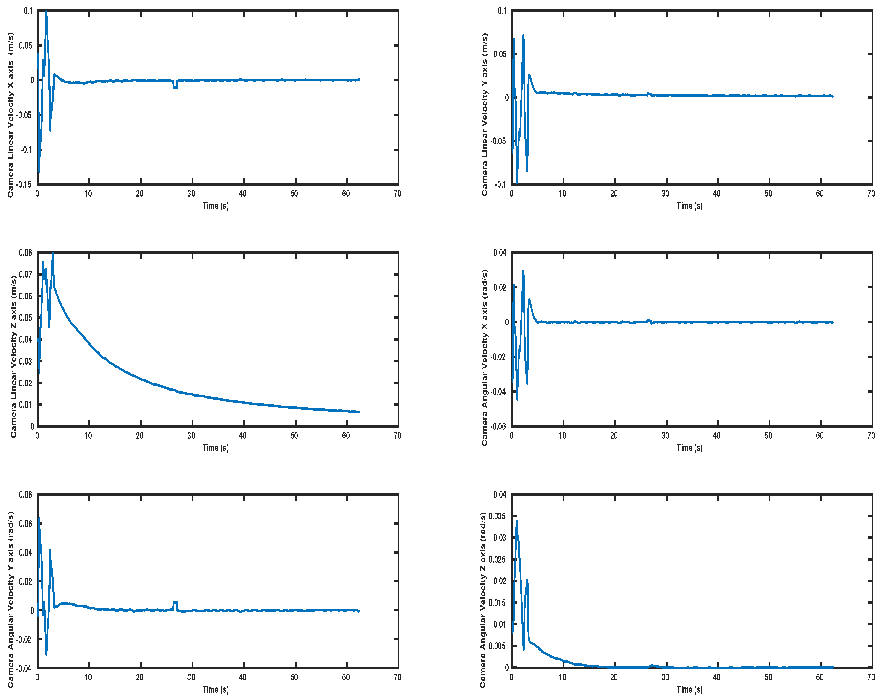
Similarly, Figure 7 depicts the performance of the system velocity errors. The parameters of the performance functions for the vehicle (ROV) DoFs (Surge, Sway, Heave, Yaw) were set at ρ ζ R O V 0 = 1.5 , ρ ζ R O V = 0.2 , λ R O V = 0.25 . The parameters of the performance functions for the manipulator joints were set at ρ ζ m a n 0 = 1.5 , ρ ζ m a n = 0.3 , λ m a n = 0.25 . As it can be observed from Figure 7 the system velocity errors were constantly preserved within their corresponding performance envelopes. Therefore, the predefined behavior in terms of overshoot, rate of convergence and steady state was satisfied. The evolution of the underwater vehicle’s control inputs in the form of generalized forces & torques is presented in Figure 8. The control bounds of the vehicle are [ F ̲ X R O V , F ¯ X R O V ] = [ 68.7 , 68.7 ] , [ F ̲ Y R O V , F ¯ Y R O V ] = [ 29.4 , 29.4 ] , [ F ̲ Z R O V , F ¯ Z R O V ] = [ 29.4 , 29.4 ] , [ N ̲ R O V , N ¯ R O V ] = [ 8.4 , 8.4 ] . Therefore, it is clearly shown that the vehicle control inputs are always kept within these bounds. The manipulator’s control inputs in the form of joint torques are presented in Figure 9. The control bounds of the manipulator joints are [ τ q ̲ m 1 , τ q ¯ m 1 ] = [ 3.5 , 3.5 ] , [ τ q ̲ m 2 , τ q ¯ m 2 ] = [ 2.8 , 2.8 ] , [ τ q ̲ m 3 , τ q ¯ m 3 ] = [ 1.5 , 1.5 ] , [ τ q ̲ m 4 , τ q ¯ m 4 ] = [ 1.5 , 1.5 ] . Hence, the manipulator control inputs are always kept within these bounds. Moreover, the evolution of the vehicle as well as the manipulator joints states during the simulation operation are presented in Figure 10 and Figure 11, respectively. The bounds of the manipulator joints are [ q ̲ m 1 , q ¯ m 1 ] = [ π , π ] , [ q ̲ m 2 , q ¯ m 2 ] = [ π / 2 , 0.36 π ] , [ q ̲ m 3 , q ¯ m 3 ] = [ 0.72 π , π / 2 ] , [ q ̲ m 4 , q ¯ m 4 ] = [ π , π ] . It can be easily seen that the manipulator joint limits were preserved during the complete operation. Finally, the evolution of the camera frame’s velocities is given in Figure 12, where it can be observed that they converge close to zero as the system reaches its desired position.

5.2.2. Scenario 2

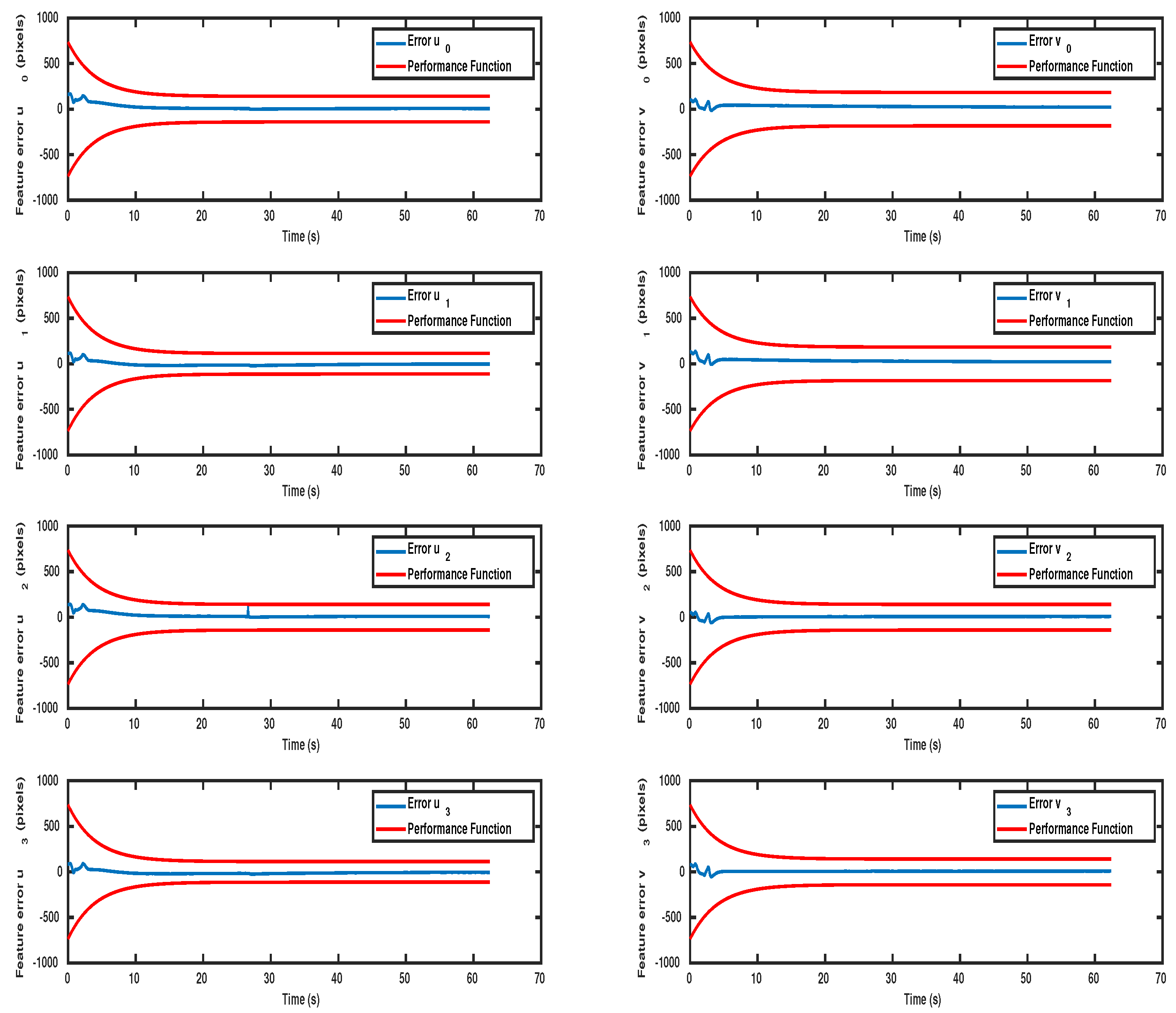
In the second scenario, the UVMS is initialized at the configuration depicted in Figure 5a. More specifically, the vehicle was located at [ x υ , y υ , z υ , ψ υ ] = [ 1.4 , 2.7 , 2.3 , 1.57 ] and the manipulator’s joints were configured at [ q m 1 , q m 2 , q m 3 , q m 4 ] = [ 0.35 , 0.4 , 0.4 , 0.1 ] , which also led to a challenging initial configuration, s s 2 0 = 416 493 390 464 294 326 369 402 , very close to the image boundaries. The parameters of the performance functions were set at the same values as in Scenario 1. The evolution of image features errors is depicted in Figure 13. As it can be easily observed, the feature coordinate errors were retained within the corresponding performance envelopes and consequently the visibility constraints were continuously satisfied. The system was again successfully guided to the desired configuration as depicted in Figure 5b.
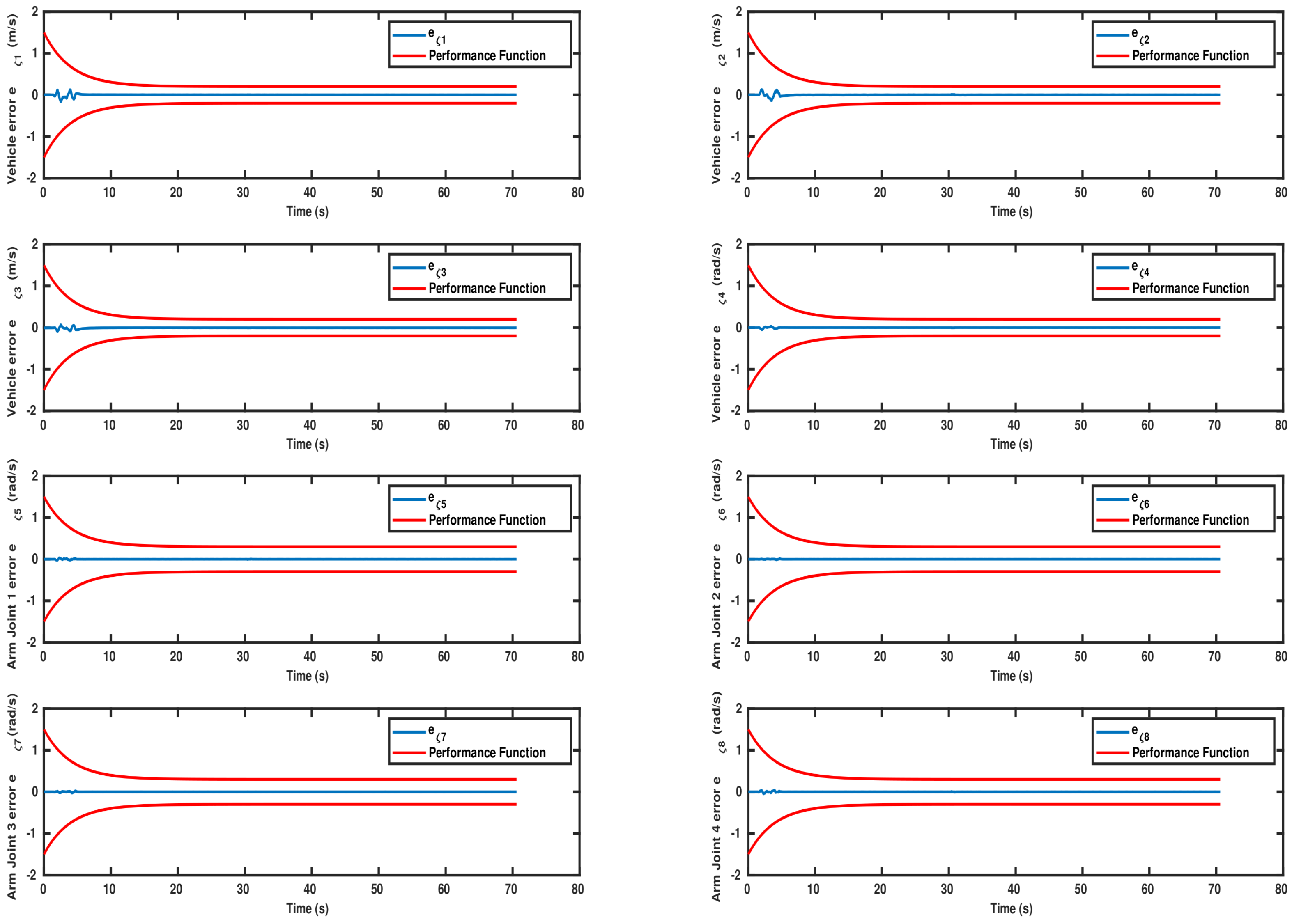
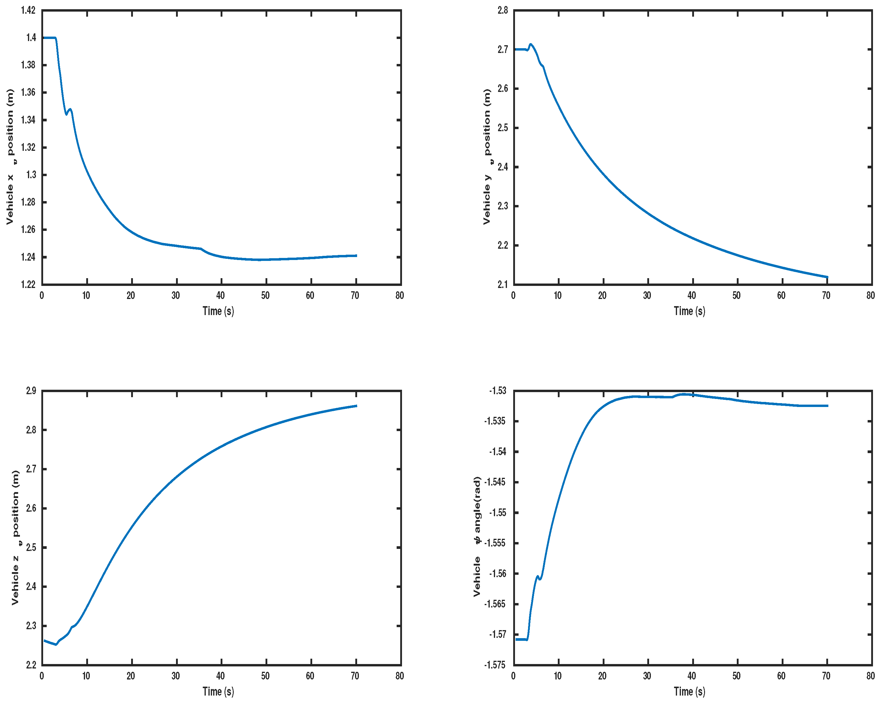
Likewise, Figure 14 depicts the performance of the system velocity errors in the second scenario. The parameters of the performance functions for the vehicle and the manipulator joints were set at the same values as in Scenario 1. As it can be observed from Figure 14 the system velocity errors were constantly preserved within their corresponding performance envelopes. Therefore, the predefined behavior in terms of overshoot, rate of convergence and steady state was satisfied. The evolution of the underwater vehicle’s control inputs in the form of generalized forces & torques as well as the manipulator’s control inputs in the form of joint torques are indicated in Figure 15 and Figure 16, respectively. The control inputs for the vehicle and the manipulator are always preserved within the operational bounds. Moreover, the evolution of the vehicle as well as the manipulator joints states during the simulation operation are presented in Figure 17 and Figure 18, respectively. The manipulator joint limits were again preserved during the complete operation. The evolution of the camera frame’s velocities is given in Figure 19, where it can also observed that they converge close to zero as the system reaches its desired position.
The performance of the proposed IBVS framework is also demonstrated at a short video that can be found at the following https://youtu.be/dO51LNMMADE accessed date (3 July 2022).
As mentioned previously, the evaluation of the proposed method was realized in a simulation framework. However, in a real system, we expect lower convergence rate and possibly more oscillations during the transient response. This expected behavior will be mainly due to external disturbances (e.g., ocean currents for an underwater vehicle manipulator system), sensor noises (camera, encoders, navigation system) and the difference in latency between the joint motors and the motor thrusters, where the latter usually exhibit faster response. However, the closed loop will retain its stability properties and the errors will converge close to zero with prescribed performance. In any case, the employed simulation framework is quite realistic, since it includes the dynamics of the complete system and also the target detection algorithm runs in real time on raw images.

6. Conclusions

In this study, we presented an IBVS control scheme for Floating Base Mobile Manipulator Systems. We adopted the prescribed performance control technique, which is able to guarantee predefined transient and steady state performance specifications on the image feature errors and satisfy field of view constraints, without incorporating any information regarding the system dynamics, the exogenous disturbances and in the presence of inevitable camera calibration and depth measurement errors. Various performance specifications such as: (i) maintenance of predefined behavior in terms of overshoot, convergence rate and maximum steady-state error, (ii) compliance with the system’s operational limitations (e.g., manipulator joint limits) and (iii) robust steady-state can be simultaneously achieved. The efficiency of the proposed scheme was demonstrated via a realistic simulation study from different initial camera configurations, using an eye-in-hand Underwater Vehicle Manipulator System (UVMS) as a test FBMMS platform.

Author Contributions

Conceptualization, G.C.K. and S.H.-A.; methodology, S.H.-A., G.C.K. and C.P.B.; software and simulations, G.C.K. and G.K.F.; formal analysis, S.H.-A. and A.N.; writing—original draft preparation S.H.-A., G.C.K. and A.N.; writing—review and editing, G.K.F. and C.P.B.; supervision, G.K.F. and C.P.B. All authors have read and agreed to the published version of the manuscript.

Funding

This research received no external funding.

Institutional Review Board Statement

Not applicable.

Informed Consent Statement

Not applicable.

Data Availability Statement

Not applicable.

Conflicts of Interest

The authors declare no conflict of interest.

References

  1. Sereinig, M.; Werth, W.; Faller, L.M. A review of the challenges in mobile manipulation: Systems design and RoboCup challenges. E I Elektrotechnik Inf. 2020, 137, 297–308. [Google Scholar] [CrossRef]
  2. Lang, H.; Khan, M.T.; Tan, K.K.; de Silva, C.W. Developments in visual servoing for mobile manipulation. Unmanned Syst. 2013, 1, 143–162. [Google Scholar] [CrossRef]
  3. Sarapura, J.A.; Roberti, F.; Carelli, R. Adaptive 3D Visual Servoing of a Scara Robot Manipulator with Unknown Dynamic and Vision System Parameters. Automation 2021, 2, 127–140. [Google Scholar] [CrossRef]
  4. Heshmati-Alamdari, S.; Karras, G.C.; Kyriakopoulos, K.J. A predictive control approach for cooperative transportation by multiple underwater vehicle manipulator systems. IEEE Trans. Control Syst. Technol. 2021, 30, 917–930. [Google Scholar] [CrossRef]
  5. Parlaktuna, O.; Ozkan, M. Adaptive control of free-floating space manipulators using dynamically equivalent manipulator model. Robot. Auton. Syst. 2004, 46, 185–193. [Google Scholar] [CrossRef]
  6. Nanos, K.; Papadopoulos, E.G. On the dynamics and control of free-floating space manipulator systems in the presence of angular momentum. Front. Robot. AI 2017, 4, 26. [Google Scholar] [CrossRef]
  7. Gao, J.; Liang, X.; Chen, Y.; Zhang, L.; Jia, S. Hierarchical image-based visual serving of underwater vehicle manipulator systems based on model predictive control and active disturbance rejection control. Ocean Eng. 2021, 229, 108814. [Google Scholar] [CrossRef]
  8. Lippiello, V.; Fontanelli, G.A.; Ruggiero, F. Image-based visual-impedance control of a dual-arm aerial manipulator. IEEE Robot. Autom. Lett. 2018, 3, 1856–1863. [Google Scholar] [CrossRef]
  9. Thomas, J.; Loianno, G.; Sreenath, K.; Kumar, V. Toward image based visual servoing for aerial grasping and perching. In Proceedings of the 2014 IEEE International Conference on Robotics and Automation (ICRA), Hong Kong, China, 31 May–7 June 2014; pp. 2113–2118. [Google Scholar]
  10. Heshmati-Alamdari, S.; Bechlioulis, C.P.; Karras, G.C.; Kyriakopoulos, K.J. Cooperative impedance control for multiple underwater vehicle manipulator systems under lean communication. IEEE J. Ocean. Eng. 2020, 46, 447–465. [Google Scholar] [CrossRef]
  11. Han, H.; Wei, Y.; Ye, X.; Liu, W. Motion planning and coordinated control of underwater vehicle-manipulator systems with inertial delay control and fuzzy compensator. Appl. Sci. 2020, 10, 3944. [Google Scholar] [CrossRef]
  12. Logothetis, M.; Karras, G.C.; Heshmati-Alamdari, S.; Vlantis, P.; Kyriakopoulos, K.J. A model predictive control approach for vision-based object grasping via mobile manipulator. In Proceedings of the 2018 IEEE/RSJ International Conference on Intelligent Robots and Systems (IROS), Madrid, Spain, 1–5 October 2018; pp. 1–6. [Google Scholar]
  13. Rastegarpanah, A.; Aflakian, A.; Stolkin, R. Improving the Manipulability of a Redundant Arm Using Decoupled Hybrid Visual Servoing. Appl. Sci. 2021, 11, 11566. [Google Scholar] [CrossRef]
  14. Chaumette, F.; Hutchinson, S. Visual servo control. I. Basic approaches. IEEE Robot. Autom. Mag. 2006, 13, 82–90. [Google Scholar] [CrossRef]
  15. Chaumette, F.; Hutchinson, S. Visual servo control. Part II: Advanced approaches. IEEE Robot. Autom. Mag. 2007, 14, 109–118. [Google Scholar] [CrossRef]
  16. Silveira, G.; Malis, E. Direct visual servoing: Vision-based estimation and control using only nonmetric information. IEEE Trans. Robot. 2012, 28, 974–980. [Google Scholar] [CrossRef]
  17. Heshmati-alamdari, S.; Karavas, G.K.; Eqtami, A.; Drossakis, M.; Kyriakopoulos, K.J. Robustness Analysis of Model Predictive Control for Constrained Image-Based Visual Servoing. In Proceedings of the IEEE International Conference on Robotics and Automation, Hong Kong, China, 31 May–7 June 2014. [Google Scholar]
  18. Huang, Y. A Switched Approach to Image-Based Stabilization for Nonholonomic Mobile Robots with Field-of-View Constraints. Appl. Sci. 2021, 11, 10895. [Google Scholar] [CrossRef]
  19. Chaumette, F. Potential Problems of Stability and Convergence in Image-Based and Position-Based Visual Servoing; LNCIS Series, No 237; Springer: Berlin/Heidelberg, Germany, 1998; pp. 66–78. [Google Scholar]
  20. Kazemi, M.; Gupta, K.; Mehrandezh, M. Global Path Planning for Robust Visual Servoing in Complex Environments. In Proceedings of the 2009 IEEE International Conference on Robotics and Automation, Kobe, Japan, 12–17 May 2009; pp. 1726–1732. [Google Scholar]
  21. Mezouar, Y.; Chaumette, F. Path Planning for Robust Image-based Control. IEEE Trans. Robot. Autom. 2002, 18, 534–549. [Google Scholar] [CrossRef] [Green Version]
  22. Sauvée, M.; Poignet, P.; Dombre, E.; Courtial, E. Image based visual servoing through nonlinear model predictive control. In Proceedings of the 45th IEEE Conference on Decision and Control, San Diego, CA, USA, 13–15 December 2006; pp. 1776–1781. [Google Scholar]
  23. Lee, D.; Lim, H.; Kim, H.J. Obstacle avoidance using image-based visual servoing integrated with nonlinear model predictive control. In Proceedings of the 2011 50th IEEE Conference on Decision and Control and European Control Conference, Orlando, FL, USA, 12–15 December 2011; pp. 5689–5694. [Google Scholar]
  24. Allibert, G.; Courtial, E.; Touré, Y. Real-time visual predictive controller for image-based trajectory tracking of a mobile robot. IFAC Proc. Vol. 2008, 41, 11244–11249. [Google Scholar] [CrossRef]
  25. Heshmati-alamdari, S.; Eqtami, A.; Karras, G.C.; Dimarogonas, D.V.; Kyriakopoulos, K.J. A Self-triggered Position Based Visual Servoing Model Predictive Control Scheme for Underwater Robotic Vehicles. Machines 2020, 8, 33. [Google Scholar] [CrossRef]
  26. Chesi, G. Visual servoing path planning via homogeneous forms and LMI optimizations. IEEE Trans. Robot. 2009, 25, 281–291. [Google Scholar] [CrossRef]
  27. Heshmati-alamdari, S.; Bechlioulis, C.P.; Liarokapis, M.V.; Kyriakopoulos, K.J. Prescribed Performance Image Based Visual Servoing under Field of View Constraints. In Proceedings of the IEEE/RSJ International Conference on Intelligent Robots and Systems (IROS), Chicago, IL, USA, 14–18 September 2014. [Google Scholar]
  28. Bechlioulis, C.P.; Heshmati-alamdari, S.; Karras, G.C.; Kyriakopoulos, K.J. Robust image-based visual servoing with prescribed performance under field of view constraints. IEEE Trans. Robot. 2019, 35, 1063–1070. [Google Scholar] [CrossRef]
  29. Belmonte, Á.; Ramón, J.L.; Pomares, J.; Garcia, G.J.; Jara, C.A. Optimal image-based guidance of mobile manipulators using direct visual servoing. Electronics 2019, 8, 374. [Google Scholar] [CrossRef] [Green Version]
  30. Alepuz, J.P.; Emami, M.R.; Pomares, J. Direct image-based visual servoing of free-floating space manipulators. Aerosp. Sci. Technol. 2016, 55, 1–9. [Google Scholar] [CrossRef]
  31. Zhao, X.; Xie, Z.; Yang, H.; Liu, J. Minimum base disturbance control of free-floating space robot during visual servoing pre-capturing process. Robotica 2020, 38, 652–668. [Google Scholar] [CrossRef]
  32. Laiacker, M.; Huber, F.; Kondak, K. High accuracy visual servoing for aerial manipulation using a 7 degrees of freedom industrial manipulator. In Proceedings of the 2016 IEEE/RSJ International Conference on Intelligent Robots and Systems (IROS), Daejeon, Korea, 9–14 October 2016; pp. 1631–1636. [Google Scholar]
  33. Marchionne, C.; Sabatini, M.; Gasbarri, P. GNC architecture solutions for robust operations of a free-floating space manipulator via image based visual servoing. Acta Astronaut. 2021, 180, 218–231. [Google Scholar] [CrossRef]
  34. Lippiello, V.; Cacace, J.; Santamaria-Navarro, A.; Andrade-Cetto, J.; Trujillo, M.A.; Esteves, Y.R.R.; Viguria, A. Hybrid visual servoing with hierarchical task composition for aerial manipulation. IEEE Robot. Autom. Lett. 2015, 1, 259–266. [Google Scholar] [CrossRef] [Green Version]
  35. Zhang, G.; Wang, B.; Wang, J.; Liu, H. A hybrid visual servoing control of 4 DOFs space robot. In Proceedings of the 2009 International Conference on Mechatronics and Automation, Changchun, China, 9–12 August 2009; pp. 3287–3292. [Google Scholar]
  36. Buonocore, L.R.; Cacace, J.; Lippiello, V. Hybrid visual servoing for aerial grasping with hierarchical task-priority control. In Proceedings of the 2015 23rd Mediterranean Conference on Control and Automation (MED), Torremolinos, Spain, 16–19 June 2015; pp. 617–623. [Google Scholar]
  37. Quan, F.; Chen, H.; Li, Y.; Lou, Y.; Chen, J.; Liu, Y. Singularity-Robust Hybrid Visual Servoing Control for Aerial Manipulator. In Proceedings of the 2018 IEEE International Conference on Robotics and Biomimetics (ROBIO), Kuala Lumpur, Malaysia, 12–15 December 2018; pp. 562–568. [Google Scholar]
  38. Antonelli, G. Underwater Robots; Springer Tracts in Advanced Robotics; Springer International Publishing: Cham, Switzerland, 2013. [Google Scholar]
  39. Karras, G.C.; Bechlioulis, C.P.; Fourlas, G.K.; Kyriakopoulos, K.J. Target Tracking with Multi-rotor Aerial Vehicles based on a Robust Visual Servo Controller with Prescribed Performance. In Proceedings of the 2020 International Conference on Unmanned Aircraft Systems (ICUAS), Athens, Greece, 1–4 September 2020; pp. 480–487. [Google Scholar]
  40. Hutchinson, S.; Hager, G.D.; Corke, P.I. A tutorial on visual servo control. IEEE Trans. Robot. Autom. 1996, 12, 651–670. [Google Scholar] [CrossRef] [Green Version]
  41. Bechlioulis, C.; Rovithakis, G. Prescribed performance adaptive control for multi-input multi-output affine in the control nonlinear systems. IEEE Trans. Autom. Control 2010, 55, 1220–1226. [Google Scholar] [CrossRef]
  42. Heshmati-Alamdari, S.; Bechlioulis, C.P.; Karras, G.C.; Nikou, A.; Dimarogonas, D.V.; Kyriakopoulos, K.J. A robust interaction control approach for underwater vehicle manipulator systems. Annu. Rev. Control 2018, 46, 315–325. [Google Scholar] [CrossRef]
  43. Bechlioulis, C.; Rovithakis, G. A low-complexity global approximation-free control scheme with prescribed performance for unknown pure feedback systems. Automatica 2014, 50, 1217–1226. [Google Scholar] [CrossRef]
  44. Prats, M.; Perez, J.; Fernandez, J.; Sanz, P. An open source tool for simulation and supervision of underwater intervention missions. In Proceedings of the IEEE/RSJ International Conference on Intelligent Robots and Systems (IROS), Macau, China, 4–8 November 2012; pp. 2577–2582. [Google Scholar]
  45. Malis, E.; Rives, P. Robustness of image-based visual servoing with respect to depth distribution errors. In Proceedings of the 2003 IEEE International Conference on Robotics and Automation (Cat. No.03CH37422), Taipei, Taiwan, 14–19 September 2003; Volume 1, pp. 1056–1061. [Google Scholar]
  46. Siciliano, B.; Slotine, J.J.E. A general framework for managing multiple tasks in highly redundant robotic systems. In Advanced Robotics, Proceedings of the 91 ICAR, Fifth International Conference on “Robots in Unstructured Environments”, Pisa, Italy, 19–22 June 1991; IEEE: Piscataway, NJ, USA; Volume 2, pp. 1211–1216.
  47. Simetti, E.; Casalino, G. A Novel Practical Technique to Integrate Inequality Control Objectives and Task Transitions in Priority Based Control. J. Intell. Robot. Syst. Theory Appl. 2016, 84, 877–902. [Google Scholar] [CrossRef]
  48. Soylu, S.; Buckham, B.; Podhorodeski, R. Redundancy resolution for underwater mobile manipulators. Ocean Eng. 2010, 37, 325–343. [Google Scholar] [CrossRef]
  49. Sontag, E. Mathematical Control Theory: Deterministic Finite Dimensional Systems; Texts in Applied Mathematics; U.S. Government Printing Office: Washington, DC, USA, 1998.
  50. Quigley, M.; Conley, K.; Gerkey, B.P.; Faust, J.; Foote, T.; Leibs, J.; Wheeler, R.; Ng, A.Y. ROS: An open-source Robot Operating System. Icra Workshop Open Source Softw. 2009, 3, 5. [Google Scholar]
  51. Kato, H.; Billinghurst, M. Marker Tracking and HMD Calibration for a Video-based Augmented Reality Conferencing System. In Proceedings of the 2nd International Workshop on Augmented Reality (IWAR 99), San Francisco, CA, USA, 20–21 October 1999. [Google Scholar]
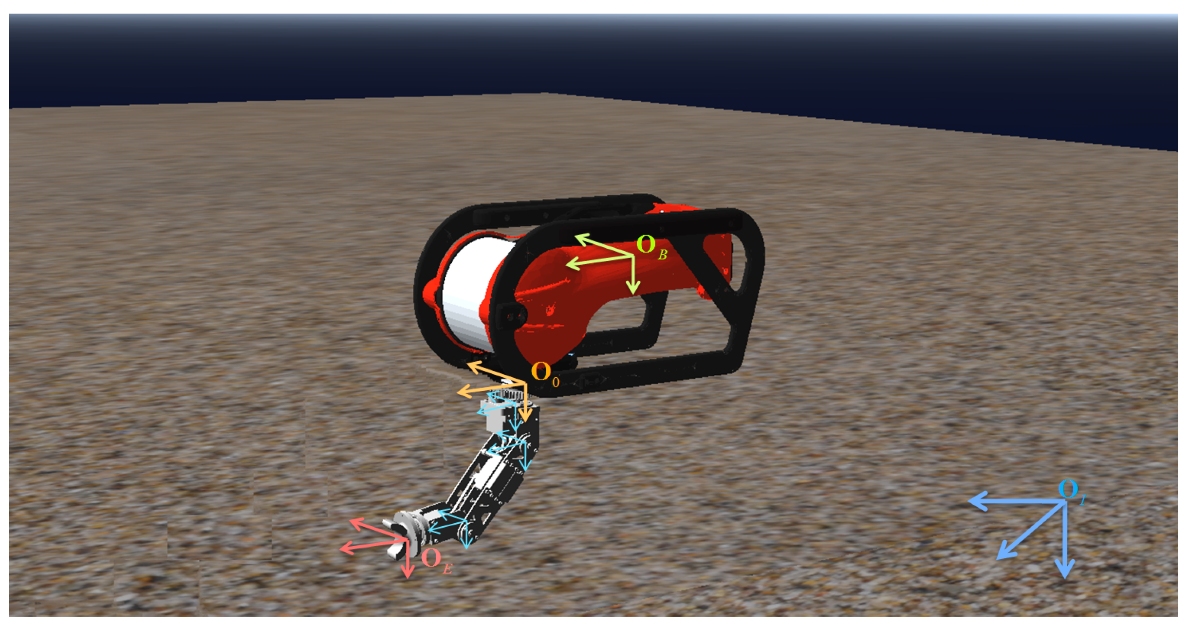
Figure 1. A Floating Base Mobile Manipulator System. The inertial, vehicle, and end-effector frames are depicted in blue, yellow and red color, respectively.
Machines 10 00547 g001
Figure 2. The central projection perspective camera model.
Machines 10 00547 g002
Figure 3. The closed loop block diagram of the proposed PP-IBVS control scheme for free Floating Base Mobile Manipulator Systems (FBMMSs).
Machines 10 00547 g003
Figure 4. Scenario 1 Experimental Setup: (a) Initial pose configuration, (b) desired pose configuration. The initial configuration is rather challenging for IBVS schemes, owing to the large rotation of the camera frame as well as the large distance relative to the target configuration. The system’s evolution during the experimental study is indicated with blue color. The proposed IBVS control scheme successfully guides the FBMMS to the desired configuration while simultaneously satisfying all the operational limitations.
Machines 10 00547 g004
Figure 5. Scenario 2 Experimental Setup: (a) Initial pose configuration, (b) desired pose configuration. The initial configuration is also very challenging for an IBVS control scheme. The system’s evolution during the experimental study is indicated with blue color. The proposed IBVS control scheme achieved again the successful guidance of the FBMMS to the desired configuration while simultaneously satisfying all the operational limitations.
Machines 10 00547 g005
Figure 6. Scenario 1: The evolution of the feature coordinate errors along with the corresponding imposed performance bounds.
Machines 10 00547 g006
Figure 7. Scenario 1: The evolution of the system velocities errors along with the corresponding imposed performance bounds.
Machines 10 00547 g007
Figure 8. Scenario 1: The evolution of the control inputs of the underwater vehicle (ROV) in the form of generalized forces & torque during the simulation study.
Machines 10 00547 g008
Figure 9. Scenario 1: The evolution of the manipulator control inputs in the form of joint torques during the simulation study.
Machines 10 00547 g009
Figure 10. Scenario 1: The evolution of the vehicle states during the simulation study.
Machines 10 00547 g010
Figure 11. Scenario 1: The evolution of the manipulator joints states during the simulation study.
Machines 10 00547 g011
Figure 12. Scenario 1: The evolution of the camera velocities during the simulation study.
Machines 10 00547 g012
Figure 13. Scenario 2: The evolution of the feature coordinate errors along with the corresponding imposed performance bounds.
Machines 10 00547 g013
Figure 14. Scenario 2: The evolution of the system velocities errors along with the corresponding imposed performance bounds.
Machines 10 00547 g014
Figure 15. Scenario 2: The evolution of the control inputs of the underwater vehicle (ROV) in the form of generalized forces & torque during the simulation study.
Machines 10 00547 g015
Figure 16. Scenario 2: The evolution of the manipulator control inputs in the form of joint torques during the simulation study.
Machines 10 00547 g016
Figure 17. Scenario 2: The evolution of the vehicle states during the simulation study.
Machines 10 00547 g017
Figure 18. Scenario 2: The evolution of the manipulator joints states during the simulation study.
Machines 10 00547 g018
Figure 19. Scenario 2: The evolution of the camera velocities during the simulation study.
Machines 10 00547 g019
Publisher’s Note: MDPI stays neutral with regard to jurisdictional claims in published maps and institutional affiliations.