Abstract
The manufacturing accuracy of large-scale complex components determines the performance and quality of aircraft, ships, high-speed rail, and other equipment. High-precision 3D measurement plays a crucial role in ensuring manufacturing accuracy. At present, the existing measurement methods rely heavily on manual labor, which cannot satisfy the requirements of industry quality and efficiency. This paper introduces an integrated mobile robotic measurement system for the accurate and automatic 3D measurement of large-scale components with complex curved surfaces. The system consists of the mobile optical scanning measurement device, visual tracking device, and software platform, which can realize comprehensive and accurate data acquisition and stitching of large-scale complex components. The combination of visual tracking and 3D measurement based on the coordinated motion of the dual robot achieved the automatic data acquisition of large-scale complex components without sticking coded targets. Additionally, this paper also introduces a DeepMerge algorithm that combines local and global features of the point cloud, which effectively corrects the initial stitching error of the visual tracking system. The validity of the measurement system and method was shown by the measurement and stitching experiments on the surface of the vehicle nose, ensuring the accurate measurement of the robot’s wide range of motion.
1. Introduction
With the revolutionary development in aerospace, energy, transportation, and other fields, it has been witnessed in recent years an increased demand for the processing quality of large-scale components [1], such as aircraft wings, vehicle bodies, wind power blades, and hull surface [2,3,4,5]. The accuracy of surface manufacturing affects the performance and quality of equipment in relevant fields. Large-scale complex components are irregular and diverse, and there are a large number of hidden points on their surfaces that are difficult to measure. Traditional measurement methods cannot satisfy the requirements and accuracy of on-site measurement [6,7]. Therefore, accurate 3D data measurement is essential for surface feature extraction and machining quality inspection of complex components [8,9,10]. It is of great significance to improve the manufacturing capability of large-scale complex components by realizing the comprehensive and high-precision automatic measurement of large-scale complex components and effectively eliminating the accumulated errors in large-scale measurements.
Currently, a host of 3D measurement methods for large-scale complex components have been proposed one after another. O. Hall Holt et al. integrated a novel approach to real-time structured light range scanning [11], and the system used a standard video camera and DLP projector and produced dense range images at 60 Hz with 100 mum accuracy over a 10 cm working volume. J. Salvi et al. found through experiments that the high sensitivity to non-linearities of the camera reduces the accuracy and sensitivity to details in the surface [12]. Coordinate measuring machine (CMM) is a standard displacement system used for dimension measurement, which is the most typical measurement method at present [13,14]. Although it is highly accurate, it has many shortcomings, such as the large size of equipment, lack of flexibility, and inability to measure hidden points, failing to meet the on-site measurement requirements of complex components. The point cloud alignment is also widely used in the measurement. The point cloud measurement based on public coded targets [15] requires sticking a large number of coded targets on the surface of the component, which is inefficient. Therefore, the surface features-based method [16] is unsuitable for complex components. The local point cloud stitching that tracks the scanner pose [17,18] aims to align the local point cloud after multiple scans, which is suitable for the measurement of large-scale complex components. Yang Shourui of Tianjin University proposed a large-scale and high-accuracy automatic measurement method based on fringe projection, close-range photogrammetry, and industrial robots [19,20], which has high precision, but can only be measured within the motion range of the robot. A Paoli developed an industrial robot with two linear guide rails, whose end-effector could fix the optical scanner [21,22], and the scanner pose for point cloud alignment was acquired by the mechanical system and a total station. This method is suitable for measuring the hull of a large yacht. However, the fixed guide rails in this system limit the vertical measurement range and lack flexibility.
If the robot carrying the scanner is upgraded to an omnidirectional mobile robot, the measurement range and flexibility of the measurement system will be greatly improved. However, the precise positioning of the omnidirectional mobile robot will become a new problem, which will affect the estimation accuracy of the scanner pose and the alignment accuracy of the multi-view point cloud. Gan Z.X. et al. proposed an application of robot 3D coordinate measurement combined with laser scanning system [23]. G. Mosqueira et al. studied a special closed-loop fuze laser alignment method using industrial robots, and the average positioning accuracy reached 0.38 mm [24]. Jung M. et al. presented an alternative global localization scheme that uses dual laser scanners and the pure rotational motion of a mobile robot, and the proposed method showed sufficient efficiency and speed to be considered robust to real-world conditions and applications [25]. Zheng Wang et al. found that the laser tracker and IGPS usually have linear error through testing and will be affected by laser occlusion [26]. Although related devices such as laser sensors and GPS can solve this problem, these devices are often disturbed by environmental factors and are not suitable for this study. In recent years, visual tracking techniques have been gradually used for robot positioning [27,28], but the tracking range is limited by the field of view of the vision camera. In this regard, the team led by Tao Bo came up with a mobile robotic measurement system for large-scale complex components based on optical scanning and visual tracking, achieving the positioning of the robot by measuring scanner and coded marks on the ground. In the actual measurement of a 2.88 m wind turbine blade model, the translation error is less than 0.2 mm [29,30]. Although the measurement accuracy is very high, the ground coding and marking process also increases the complexity of the measurement task. In the paper [31], based on the new principle of dynamic triangulation with a laser scanner, the discontinuous (i.e., discrete step) scanning method is converted into continuous scanning method to eliminate the dead zone in the field of vision. In the paper [32], in the application of mobile robot navigation, the combination variable scanning step is implemented to provide accurate measurement and improve obstacle detection. All of these show that the robot mobile vision system combined with a scanner is a more suitable method for robot motion measurement.
To solve the above-mentioned problems, including the complexity of public-coded targets, inflexibility of scanner poses, and spatial limitation of visual tracking, this study proposes a dual mobile robot with a cooperative measurement system that integrates vision tracking and 3D measurement for large-scale complex workpieces. Specifically, the system includes the mobile robot, optical scanning measurement system, and visual tracking system. The mobile robot carries an optical scanner with a target installed to complete a wide range of multi-directional scanning of components. At the same time, the mobile robot has a vision system that can realize the real-time tracking and calibration of the target, which can convert all the local point cloud data obtained from each scan into a unified world coordinate system and achieve a wide range of flexible data acquisition with high accuracy for large-scale components without sticking coded targets. Additionally, this study also introduces the DeepMerge algorithm, which integrates local and global features of the point cloud, to effectively correct the cumulative error in the initial splicing process of the visual tracking so as to ensure the accuracy of the large-scale mobile measurement of robots.
2. System Composition
2.1. Overall Structure
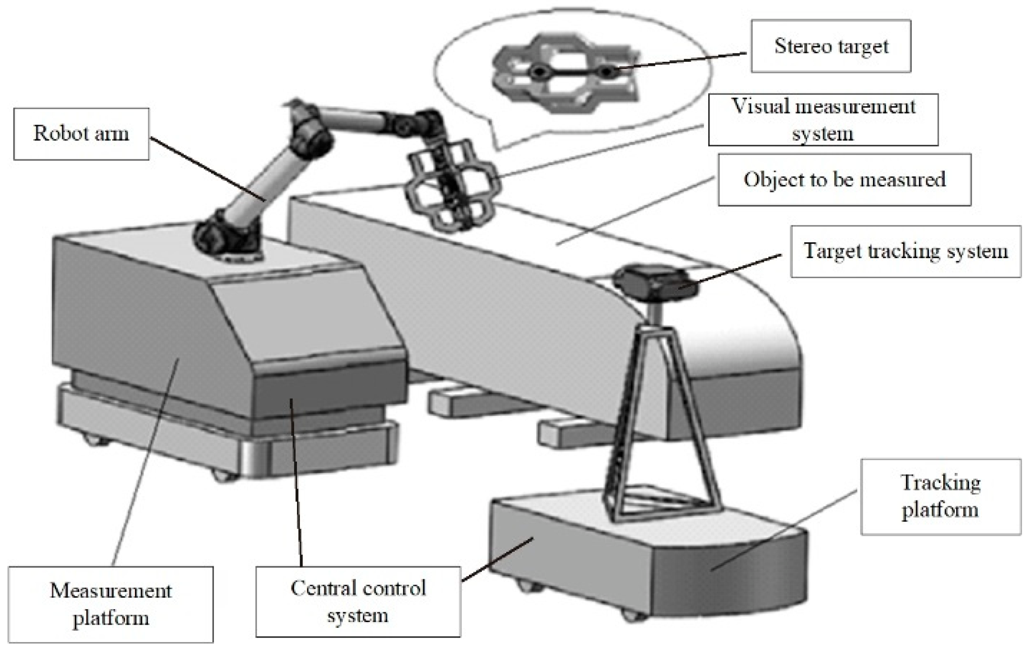
The large-scale automatic measurement system proposed in this study consists of hardware and software systems. The former includes the tracking chassis (AGV), target tracking system, measurement chassis (AGV), industrial robot, stereo target, visual measurement system, and central control system, while the latter contains the calibration module, motion planning module, measurement module, and data processing module, as shown in Figure 1.
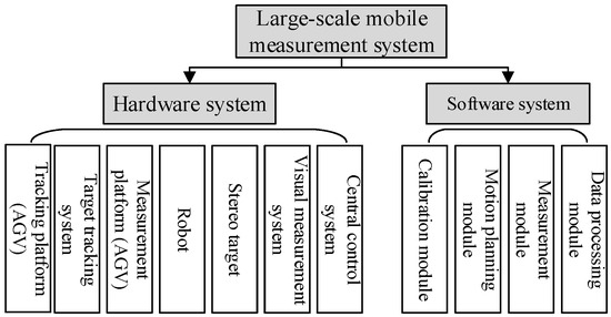
Figure 1.
Schematic diagram of the structure of the large-scale mobile measurement system.
2.2. Hardware System
The hardware system integrates the mobile robot with the function of optical measurement and the mobile robot that can perform visual tracking. The two move autonomously and work independently, completing the measurement together. The specific configuration is shown in Figure 2.
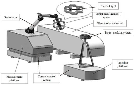
Figure 2.
Schematic diagram of the hardware system.
- (1)
- The mobile robot with the function of optical measurement consists of the measurement chassis (AGV), visual measurement system, high-precision stereo target, industrial robots, and central control system. The robot can adopt various multi-degree-of-freedom tandem industrial robots depending on the measurement tasks, with the stereo target mounted at the end of the robot. The surface of the stereo target has many targets for tracking in different directions. The visual measurement system is a binocular visual system or laser measurement system mounted in the stereo target. The central control system coordinates the work of all devices and realizes data interaction with upper-level manufacturing execution systems and other systems through standardized interfaces.
- (2)
- The mobile robot with a visual tracking function has a target tracking system, and its monocular camera is fixed on the bracket of the tracking chassis (AGV), which can obtain the position of the high-precision target on the measurement chassis in real time, thus realizing the real-time tracking and calibration of the target, converting all local point cloud data obtained each time into the unified world coordinate system, without sticking coded targets.
The above two autonomous mobile robot systems employ the AGV as the mobile chassis and adopt four-wheel drive and differential steering, which can meet the requirements of wide-range mobile measurement. These two mobile chassis (AGVs) can move collaboratively according to the paths planned by the motion planning module to achieve a wide range of automated measurement data acquisition. Compared with the traditional fixed measurement by the robot, this system has obvious advantages in terms of measurement efficiency and flexibility.
2.3. Software Platform
The central control system is the operation platform of the measurement system, which coordinates and controls the related equipment of each subsystem to complete the collaborative measurement and realize the unified management of all equipment. The mobile chassis (AGV) and robot system complete the corresponding movement under the command of the central control system. The composition of the software platform modules is shown in Figure 3.
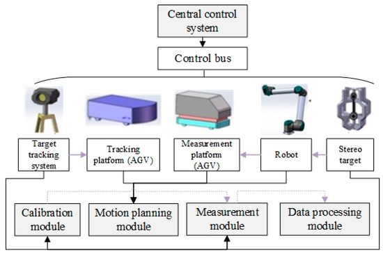
Figure 3.
Schematic diagram of software platform modules.
The composition of the software platform modules is as follows:
- (1)
- Calibration module. The function of this module is to calibrate the pose relationship between the stereo target and the visual measurement system and perform the global calibration among multiple sites (i.e., the transformation relationship between the coordinate systems of the target tracking systems of adjacent sites after coordinate transformation). The transformation matrix worked out by calibration enables the transformation of the high-density point cloud acquired by the visual measurement system to the world coordinate system of the target tracking system.
- (2)
- Motion planning module. The function of this module is to perform the path and trajectory planning for the mobile chassis (AGV) and industrial robots. Specifically, the path planning of mobile chassis (AGV) is to obtain the sequence of operating points of the two AGVs. The path planning of industrial robots is to obtain the sequence of operating points of the robot’s end-effector after the mobile chassis (AGV) carrying the robot reaches each point. The two cooperate with each other to cover all the points that need to be measured on the surface of the object to be measured. On the basis of path planning, trajectory planning is implemented to ensure the stability and continuity of the bulk movement.
- (3)
- Measurement module. The function of this module is to obtain the overall point cloud data of the complex workpiece to be measured and complete the unified stitching of the local point cloud data collected by the visual measurement system through the transformation relationship between coordinate systems of local calibration and merge them into the coordinate system of the tracking target system. After the coordinate transformation, the transformation relationship of the coordinate system obtained by global calibration is used to align and merge different point cloud segments between adjacent sites, thus obtaining the complete point cloud data to be measured.
- (4)
- Data processing module. The function of this module is to optimize the point cloud data. Due to the irregularity of complex workpieces and the limitations of measurement methods, the initial point cloud data obtained by target tracking and visual measurement systems may generate cumulative errors, so the data need to be optimized.
3. System Principle
3.1. Working Principle of Collaborative Measurement
Using the collaborative measurement by a dual mobile robot can relieve the measurement range limitation of the visual tracking system and realize the large-scale point cloud data acquisition without sticking coded targets. The working principle of collaborative measurement is as follows:
The optical measurement robot comprises the mobile chassis (AGV) and binocular optical measurement camera. The binocular optical measurement camera can obtain local high-precision 3D data of the measured object shape through a single measurement. The synergic movement of the mobile chassis and the robotic arm enables flexible adjustment of the position of the visual measurement camera, i.e., the measurement head. Through multiple movements and measurements, we can obtain all measurement data of the shape of the object to be measured, realizing flexible and accurate measurement in a wide range. Visual tracking is required to unify the measurement data at different locations into the world coordinate system.
The visual tracking robot is composed of the mobile chassis (AGV) and a monocular tracker. The monocular tracker can measure the pose of the target in real time, and the target is fixedly connected with the binocular optical measurement camera, so the real-time pose of the measurement camera can be obtained. Record the pose data of each measurement of the measurement camera, unify all the measurement data in the world coordinate system, and stitch them into complete measurement data of the object to be measured.
When the size of the object to be measured is large, the optical measurement robot and the visual tracking robot achieve the complete measurement of the large-scale workpiece through multiple alternating motions, that is, when one is in motion, the other remains stationary. The coordinate system established by the initial position of the vision tracking robot is denoted as the initial coordinate system. Through the measurement of the monocular tracker, the mapping relationship with the initial coordinate system is always maintained, and all the measurement data are unified into the initial coordinate system, that is, the world coordinate system. This method is called “coordinate transformation” in this study. During the alternating motion, the coordinate and pose transformation is performed through the pose relationship obtained by detecting the real-time pose of the target, which is finally expressed in the world coordinate system.
The coordinate systems are as shown in Figure 4. In this study, the coordinate transformation relationship of the initial coordinate system, namely the world coordinate system (W), the coordinate system for the tracking mobile chassis (V1), the coordinate system for the mobile chassis platform (V2), and the coordinate system for the robot arm base (B), the coordinate system for the end of the robot arm (E), the coordinate system for the target (T), the coordinate system for the measurement head (S), and the coordinate system for the tracker (C) were established. In this study, T denotes the transformation matrix and represents the transformation matrix from the B series to the A series.
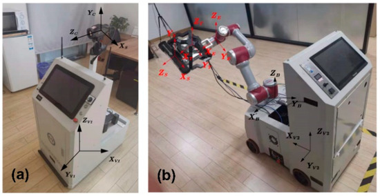
Figure 4.
Schematic diagram of the coordinate system of the mobile measurement system. (a) Visual tracking coordinate system (b) Manipulator and scanning measurement coordinate system.
The transformation of unifying the measurement data to the initial coordinate system is as follows:
where denotes the measurement data before unifying the coordinate system and denotes the measurement data after unifying the coordinate system. is obtained by measuring the target using the tracker. and are regarded as fixed values, which are obtained by calibration after installing the equipment.
If V1 and W coincide at the beginning of the measurement, is the identity matrix. If V1 is stationary and remains unchanged, the coordinate system transformation of the measurement data can be performed according to Formula (1).
When V1 moves, V2 and E are stationary, and the relationship between T and W remains unchanged, i.e., remains unchanged. If the new can be obtained using the monocular tracker, the new can be obtained based on Formula (2). The coordinate transformation of the measurement data can be performed according to Formula (1).
If the two mobile platforms move alternately in the above-mentioned manner, the mapping relationship () between L and W can always remain. If this system only relies on the measurement of C to L to complete the global positioning and navigation, it requires establishing the mapping relationship between V1, V2, and W. As was obtained, it only requires establishing the transformation relationship from T to the two mobile platforms (V1 and V2), as shown in Formulas (3) and (4).
In Formula (3), and are fixed values, which are obtained by calibration after installing the equipment. is calculated in real time by reading the joint parameters of the robot arm. In Formula (4), is obtained by calibration after installing the robot, and is obtained by measuring the target using the tracker.
Then, according to Formulas (5) and (6), the poses of the two mobile platforms in the initial coordinate system can be obtained, that is, the global positioning of the two robots is realized:
The use of the above collaborative measurement can realize the large-scale point cloud data acquisition without sticking to coded targets.
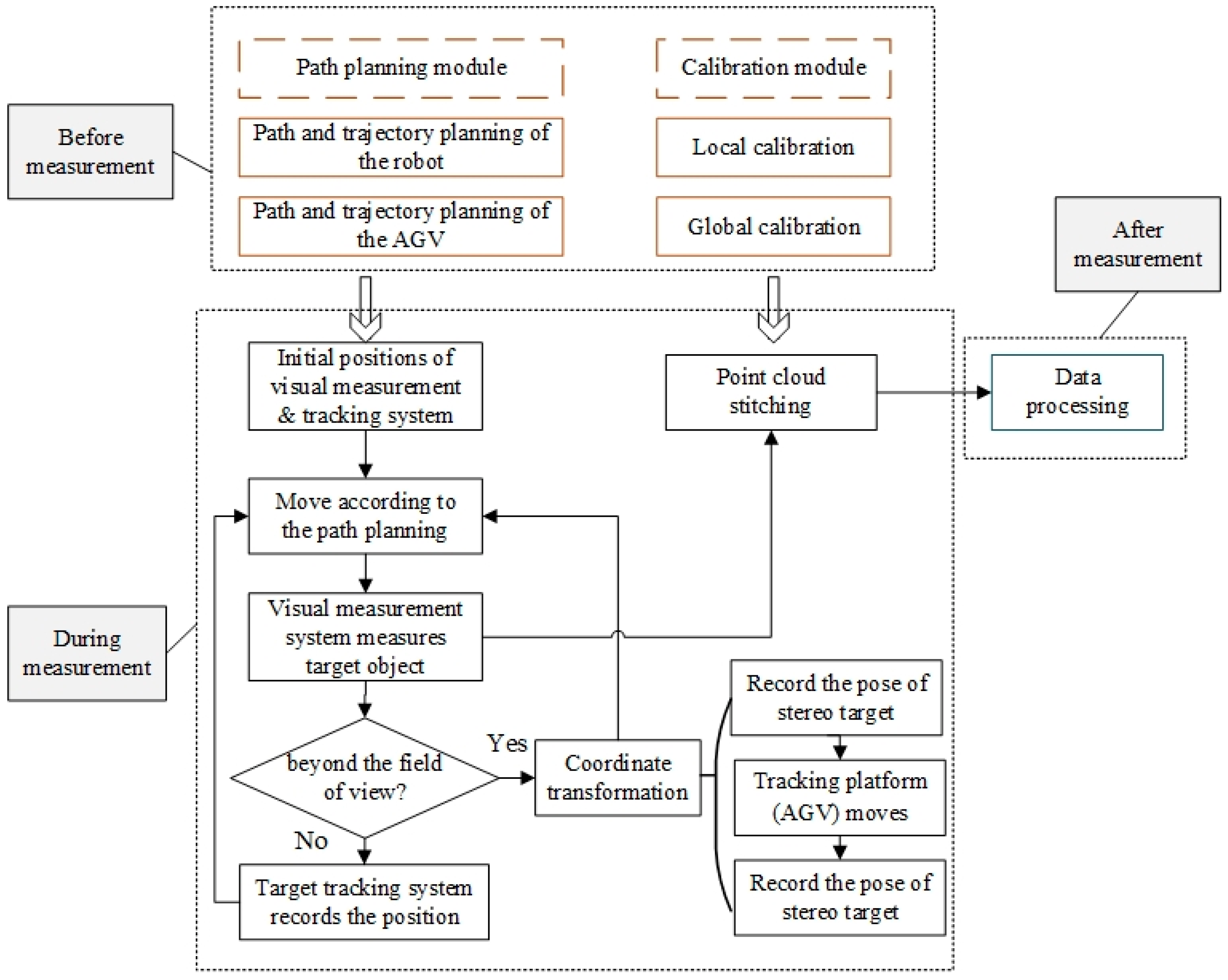
3.2. System Workflow
Figure 5 shows the schematic diagram of the main workflow of the work system. The workflow is mainly divided into three parts, namely, before measurement, during measurement, and after measurement.
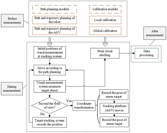
Figure 5.
Schematic diagram of the workflow.
- (1)
- Before the measurement, the path and trajectory planning are performed for the AGV and robot, and the subsequent overall measurement and acquisition program is executed according to the planned trajectory. In this part, the stereo target and vision measurement system are calibrated.
- (2)
- During the measurement, the visual measurement system, stereo target, and target tracking system are used to obtain the overall point cloud data of the components to be measured. The steps are as follows:
- a.
- First, stop the target tracking system and the visual measurement system at the initial point according to the path planning. Once the measurement starts, the visual measurement system performs the point-to-point measurement on the measured workpiece based on the path planned by the motion planning module. Meanwhile, the target tracking system records the pose of the visual measurement system at each measuring point.
- b.
- When the size of the workpiece to be measured is large, the robot needs to move forward by one station. The measurement chassis (AGV) moves forward along the planned smooth curve for a certain distance at a predetermined speed and stops, and then the visual measurement system smoothly passes the measuring point along the planned path to perform the measurement, and the target tracking system records and collects the pose of the stereo target. When the stereo target on the measurement chassis (AGV) is not within the measurement range of the target tracking system, the tracking chassis (AGV) needs to perform a coordinate transformation to continue the measurement.
- c.
- During the coordinate transformation, the target tracking system first records the pose of the stereo target, then the tracking chassis (AGV) moves forward a certain distance according to the suitable working distance of the target tracking system and stops and records the pose of the stereo target again. Next, the coordinate transformation is performed on the target tracking system according to the two sets of pose-related information of the stereo target recorded by the target tracking system. After the coordinate transformation, the target tracking system and the visual measurement system continue to perform measurement by taking photos according to Steps a and b until the task is completed.
- d.
- Stitch and merge the local point cloud data acquired by the visual measurement system into the coordinate system of the tracking target system through the local calibration of the coordinate system’s transformation relationship. After the coordinate transformation, we can align and merge different point cloud segments obtained from scanning the tracking target system between adjacent sites using the coordinate system’s transformation relationship derived from the global calibration. Finally, the point cloud data of the entire component to be measured can be obtained.
- (3)
- After measurement, optimize the measured data. The proposed intelligent algorithm (DeepMerge) is used to effectively correct the accumulative errors of the point cloud of visual tracking and stitching.
4. System Core Modules
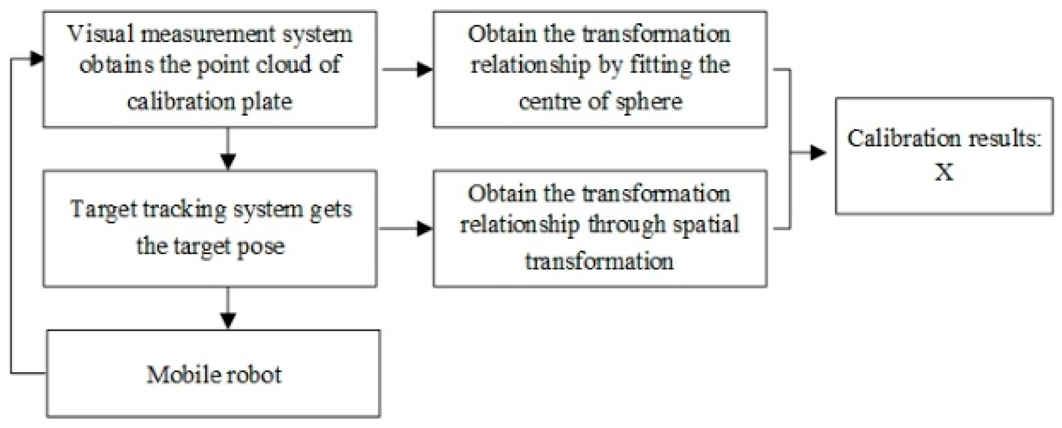
4.1. Calibration Module
As shown in Figure 6, the calibration module consists of the robot on the measurement chassis (AGV), stereo target, visual measurement system, calibration plate, and target tracking system on the tracking chassis (AGV). The target is equipped with a light source to guide the tracking system outside the measurement range to perform real-time high-precision tracking, and the target position is relatively fixed with the visual measurement system.
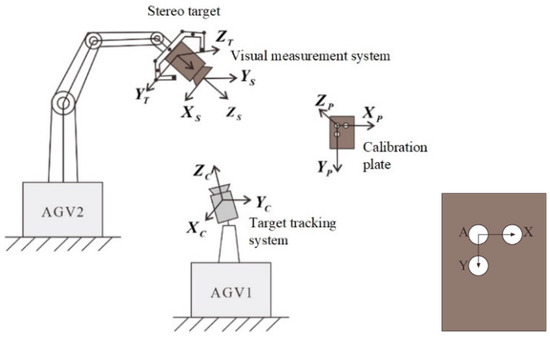
Figure 6.
System calibration principle.
The calibration plate is a plate with a uniform mesh, and a sphere for determining its pose is fixed on the surface. Assume that the centers of the three spheres are A, X, and Y, obtain the point cloud data of the calibration plate in the measurement area, and update the foot point O: assume that the equation of the line AX is and the coordinate of point B is , then the foot point O is
Assuming that is and is , can be obtained by the cross-multiplication of the two, then the space coordinate system is established with the point O as the origin, and the pose coordinate of the calibration plate after normalization is expressed as:
Placing the calibration plate within the measurable range of the measurement camera, the transformation relationship between the measurement coordinate system and the calibration coordinate system is . The positional relationship between the target and the measurement camera is relatively fixed, and the transformation relationship between the two is . The transformation relationship between the target tracking system and the stereo target is . Then:
The position of the camera and the target is measured by controlling the robot’s movement, and the feature corner points in different calibration plates are measured twice to obtain a new set of transformation relationships:
Then:
If, , , , then
After X is solved, the acquired point cloud can be converted to the target coordinate system. Based on the results of the global calibration, all the stitched point clouds can be unified to the coordinate system of the monocular camera. During the measurement process, the position between the tracking camera and the target and that between the target and the measurement camera will not change even if the robot has a certain displacement, thus avoiding rebuilding the model and re-establishing the system relationship. The specific workflow is shown in Figure 7.
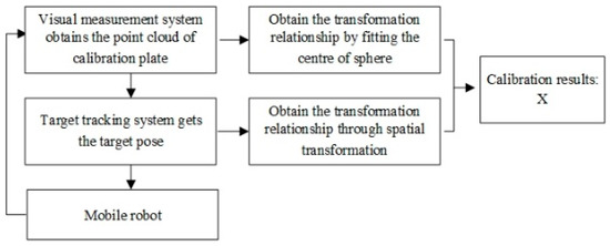
Figure 7.
Calibration module workflow.
The detailed steps of the workflow are as follows:
- (1)
- Place the calibration plate sprayed with eikonogen within the measurable range of the measuring camera to obtain the point cloud data of the calibration plate in the measurement area;
- (2)
- Import the point cloud data into Geomagic to obtain the center coordinates of the three spheres by fitting;
- (3)
- Change the pose of the target and the measurement camera by moving the robot arm and obtain the transformation relationship () between the measuring coordinate system and the calibration coordinate system under different poses. The tracking camera tracks the position of the target to obtain the transformation relationship () between the target and the tracking camera at the corresponding moment.
- (4)
- Control the distance between the measurement camera and the calibration plate within the effective field of view, collect as many data sets as possible for calculation, and obtain the calibration results. The transformation relationship between the measurement camera and the target is
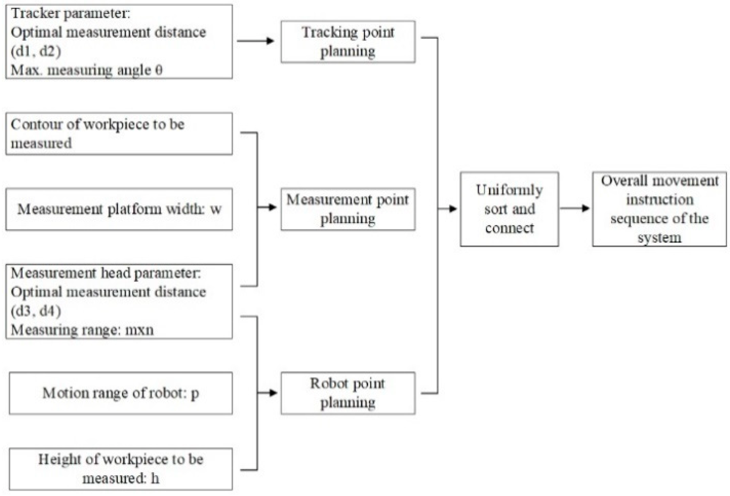
4.2. Trajectory Planning Module
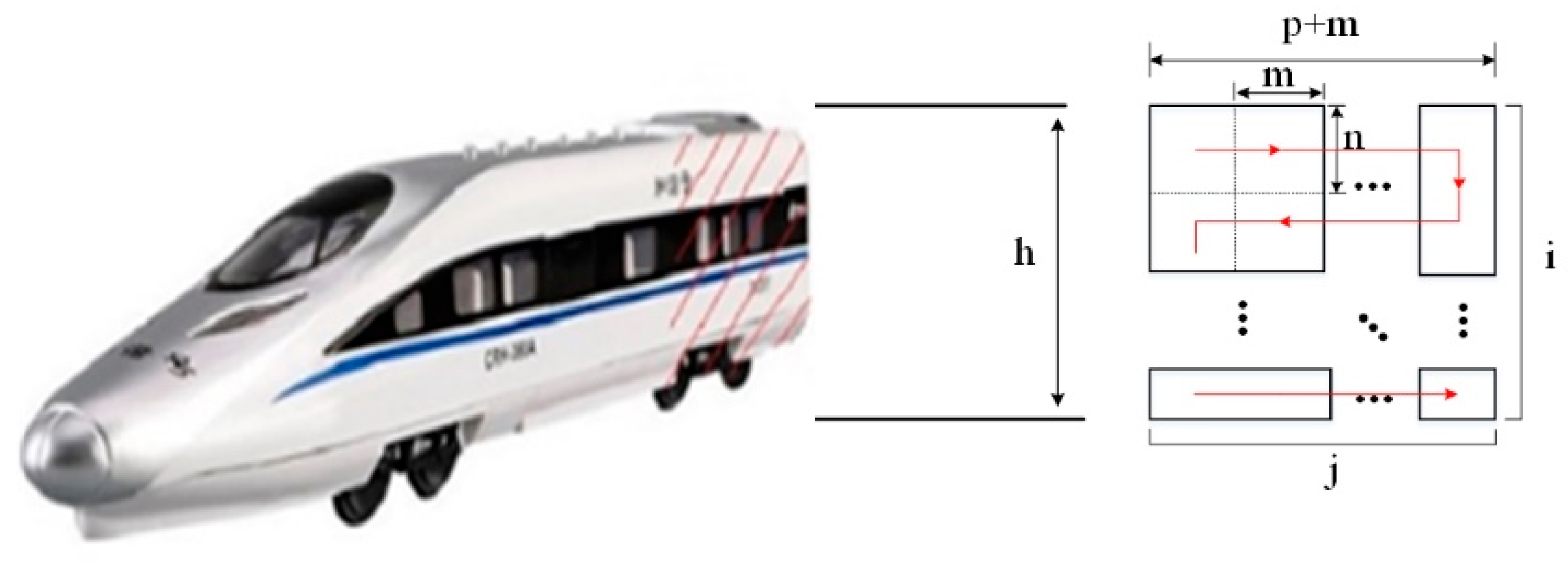
To realize the automatic, comprehensive, and accurate measurement of large-scale workpieces, this study introduces a set of autonomous trajectory planning algorithms, including the trajectory planning of optical measurement robot (AGV and robotic arm) and visual tracking robot (AGV). Assuming that the measurement range of the measuring head is a rectangle (m denotes width and n denotes height), denotes the motion range of the robot in the lateral direction, and other input parameters are shown in Figure 8. By uniformly sorting and connecting the above three groups of planning results, the overall movement instruction sequence of the system can be obtained.
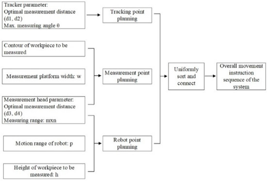
Figure 8.
Trajectory planning parameter input process.
4.2.1. Trajectory Planning of the Optical Measurement Robot
- (1)
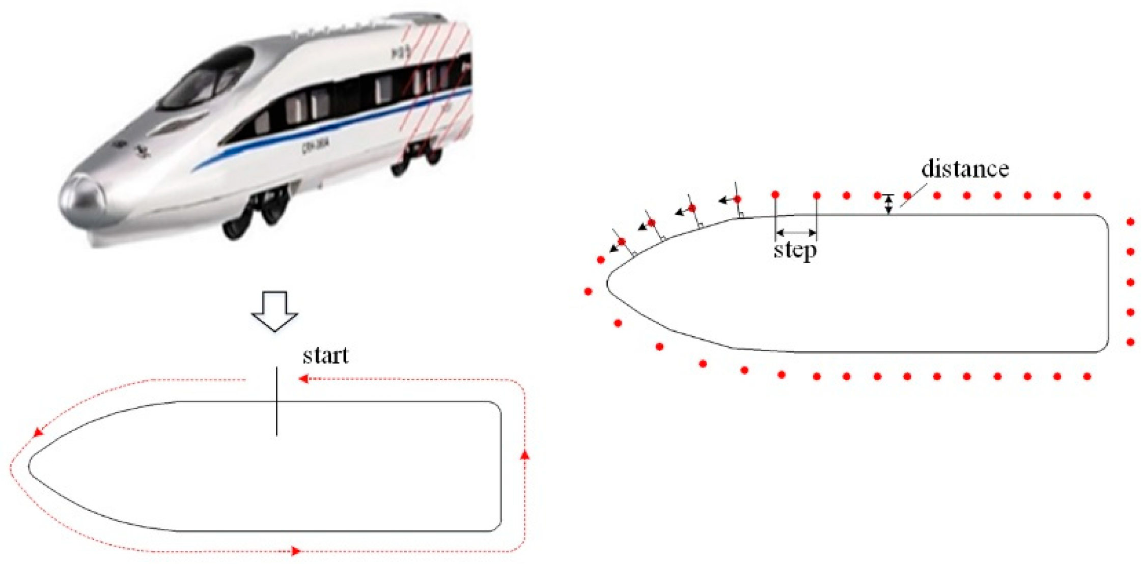
- Mobile Measuring Chassis (AGV)
By projecting the 3D design model of the measured object onto a 2D plane, a 2D closed figure can be obtained. As shown in Figure 9, it is a closed diagram obtained by projection with high-speed rail as an example. This figure can be seen as the contour of the object to be measured. A series of point locations are generated at the periphery of the contour at a uniform space (calculated based on Formulas (13) and (14)). At each point, the direction of the motion platform is perpendicular to the normal of the contour at that point.
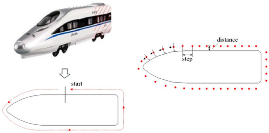
Figure 9.
The closed figure obtained by projecting the 3D model onto the 2D plane.
- (2)
- Trajectory planning for the optical measurement robot arm
In order to obtain the complete measurement data of the measured object surface, the robot needs to cover the measurement range of the measuring head to the local surface of the object, which is similar to the full coverage path planning in the path planning of mobile robot. Therefore, as shown in Figure 10, in this system, we first determined the position of the measurement boundary based on the height of the object to be measured and then performed the full coverage path planning to obtain the position sequence of the robot end-effector.
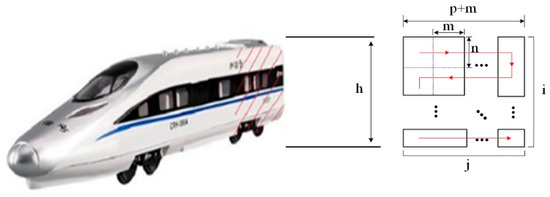
Figure 10.
Schematic diagram for the trajectory planning of the robot arm.
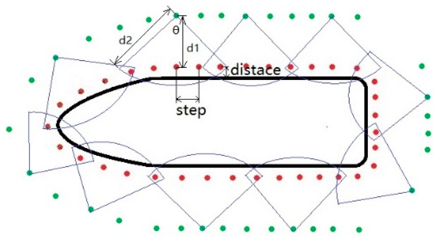
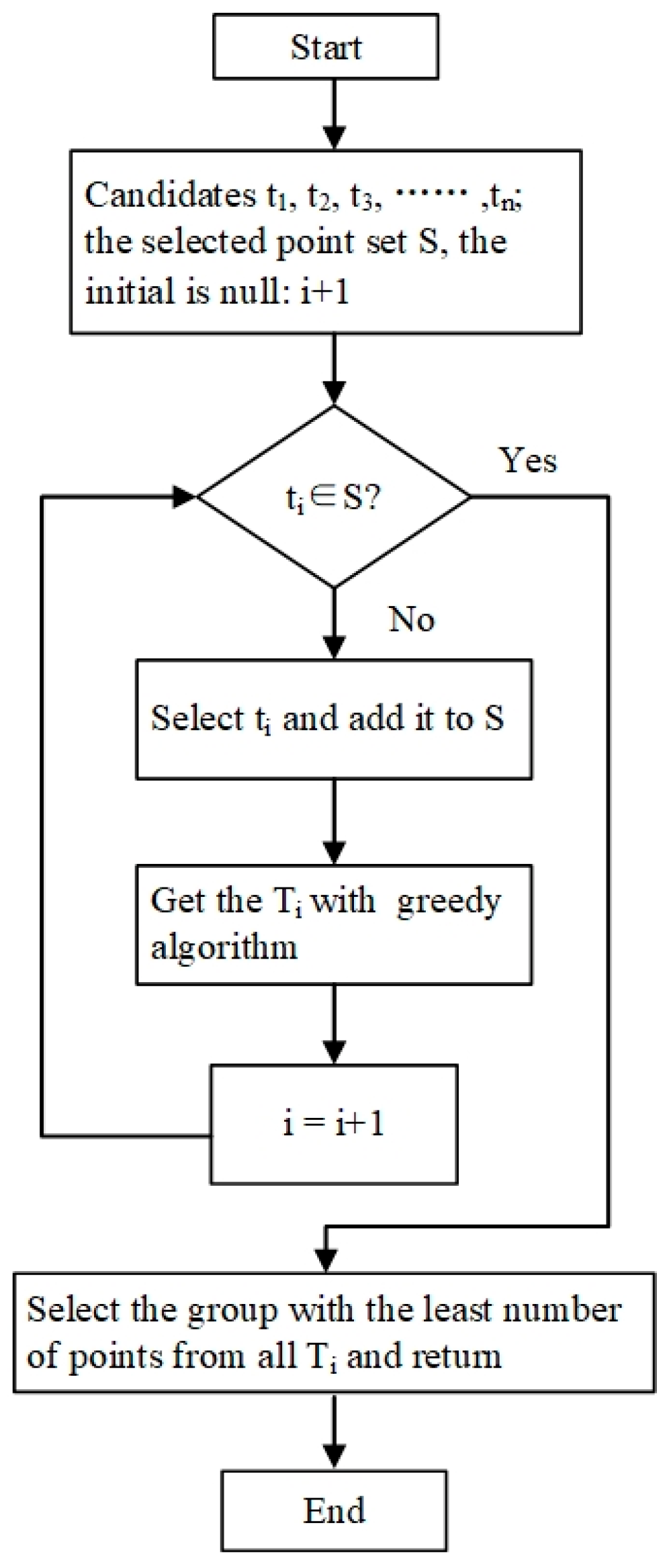
4.2.2. Trajectory Planning of the Visual Tracking Robot
The set containing all measuring points is denoted as C. A series of points () are generated at the periphery of the measuring points at a distance of d1 from each measuring point, as candidates for tracking points. According to the field of view (θ) of the tracker and the upper limit of the optimal line of sight (d2), all the measuring points that can be covered by each tracking point are calculated, and the set of measuring points that can be covered by the ti is expressed as .
Ti denotes a set of t that can cover all tracking points, namely:
To meet the conditions required for coordinate transformation, the coverage ranges of two adjacent t in Ti must have an intersection:
To minimize the number of coordinate transformations, the group with the least number of points is selected from all Ti and returned:
The schematic diagram and flow chart of the trajectory planning of the mobile tracking chassis are shown in Figure 11 and Figure 12, respectively.
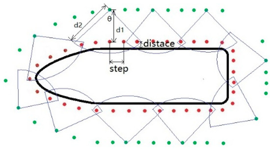
Figure 11.
Schematic diagram of the tracking chassis trajectory planning.
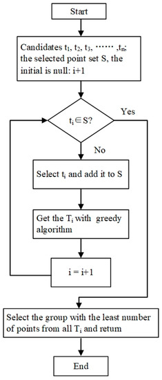
Figure 12.
Flow chart of the tracking chassis trajectory planning.
4.3. DeepMerge for Point Cloud Stitching Based on Deep Learning
As mentioned above, when the system collects the measurement data, the target tracking system completes the initial point cloud stitching. However, slight errors may occur in the stitching by the target tracking system. The DeepMerge mentioned in this study is a point cloud stitching algorithm based on the global and local features of the point cloud, which can effectively correct the initial point cloud stitching of the target system.
- (1)
- Principle of DeepMerge for point cloud stitching
Based on the initial point cloud stitching of the target tracking system, DeepMerge obtains the part with approximately the same shape and extracts the global and local features of the point cloud of this part, obtains the feature similarity matrix through the similarity of the features, and finally completes the homogeneous transformation of the point cloud stitching through the singular value decomposition module.
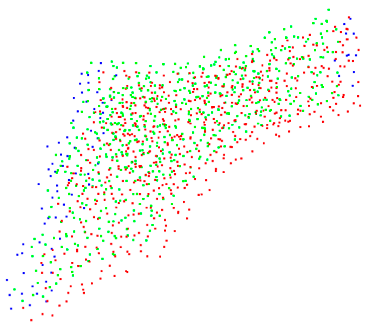
Unlike the conventional point cloud stitching algorithms, the initial point cloud stitching of this system provides us with the same shape information between the two-point clouds to be stitched. Figure 13 shows the initial point cloud stitching when the target tracking system has errors. The red and green points are the parts of the source point cloud () and the target point cloud () with the same shape. Based on the results of initial point cloud stitching, the part of the same shape of the source point cloud () and the target point cloud () has an important feature: the spacing between the corresponding points in the two-point clouds is very small. Specifically, after completing the initial point cloud stitching, the target tracking system searches for the point in the target point cloud () closest to each corresponding to the point in the source point cloud (). If the spacing between the closest point pair is less than the threshold , it is considered that the point pair belongs to the same part of the source point cloud () and the target point cloud (), and vice versa. Then, the point cloud with the same shape as the source point cloud () and the target point cloud () can be obtained.
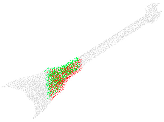
Figure 13.
Initial point cloud stitching when the target tracking system has errors.
In the source point cloud (), there are some points near the part with the same shape, and the spacing between these points and the nearest points in the target point cloud () is smaller than the threshold (), so the two parts with the same shape of the two-point clouds calculated based on the stitching results of the target tracking system are not exactly the same. As shown in Figure 14, the red and green points are the parts with the same shape in the source point cloud () and the target point cloud (), respectively, and the blue points are points that do not have the same shape according to the stitching results of the target tracking system. Therefore, it is proposed to correct the initial point cloud stitching by combining the global and local information features of the point cloud to form accurate information related to the point cloud stitching.
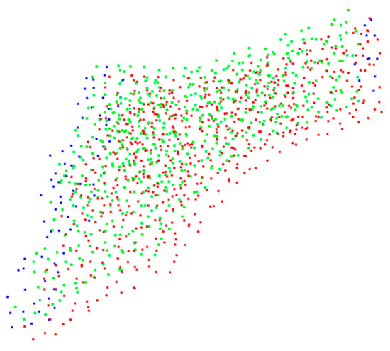
Figure 14.
The parts with approximately the same shape obtained by the solution.
The foremost thing to solve the local features of the point cloud is to stitch and correct the feature embedding extracted from the point structure consisting of points and the nearest k points in the point cloud. That is, for each point () in the point cloud, solve the coordinate () of the nearest k points. Because the neighborhood points themselves also contain some information, it is obvious that using only the coordinates of neighborhood points wastes a lot of information. The normal vector information of the neighborhood of a point proves to be the most effective and is used by many traditional algorithms.
During the point cloud processing, the calculation of the normal vector of a point on the surface is generally approximated as the estimation of the normal of a tangent plane of the surface, so it can be regarded as the estimation of the least-squares plane fit. The plane is a point set () fitted by calculating the point () of the normal vector and its nearest points . Specifically, it is assumed that the plane equation obtained by fitting the point set is:
The distance from any point () to the plane is:
Fitting the best plane is to minimize the distances from all points in the point set to the plane:
Thus, the problem of fitting the plane is converted into a problem of calculating the extrema:
The problem of calculating the extrema can be converted into a problem of calculating eigenvalues of matrix by calculating partial derivatives. Specifically, we took the partial derivative of with respect to :
Then, d can be expressed as:
Substitute into the Formula for the distance from the point to the plane:
Assuming that , , and , the partial derivatives of f with respect to a, b, and c are:
The coefficients of Formula (26) can form a 3D square matrix, and the eigenvector corresponding to the minimum eigenvalue of the square matrix is the normal vector () of the point (). Through the above calculation of normal vectors, the normal vectors () of the nearest k points to the point are found.
Additionally, the distance is a piece of very important information to be learned in the point cloud, so we can explicitly put it into the local structure of the point cloud, that is, find the distance of all the k points to the point . Finally, the nearest k points, their normal vectors, and the distances from the point to these nearest points are stitched to form a matrix, which is the final extracted local structure. By feeding the local structure of the point cloud into the neural network feature extractor, the local features of the point cloud can be obtained.
- (2)
- Model structure of DeepMerge
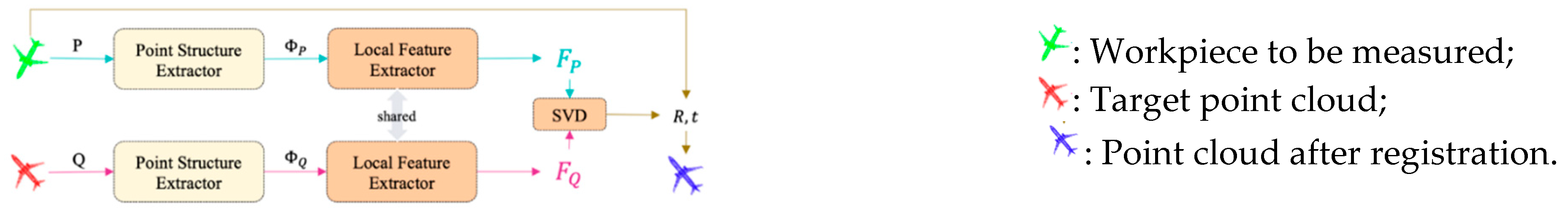
As shown in Figure 15, the entire model structure of the DeepMerge consists of three parts, including the point structure extractor, point feature extractor, and differentiable singular value decomposition module.
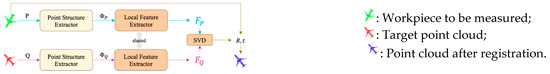
Figure 15.
Algorithm model structure.
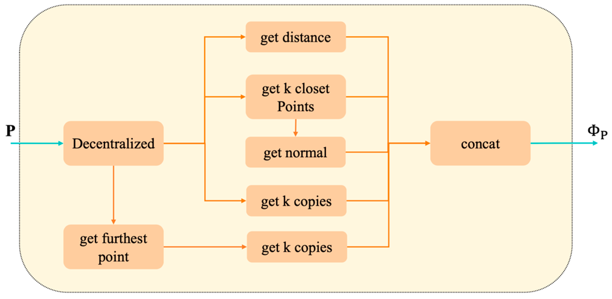
The point structure extractor of the DeepMerge is shown in Figure 16. First, all points in the point cloud are decentralized. Next, the farthest point of each point is selected. Then, the coordinates of each decentralized point and its farthest point are stitched, the local structure of the extracted point is added, and k copies of the global structure of the point are obtained and stitched with the local structure of the point, thus obtaining the point structure.
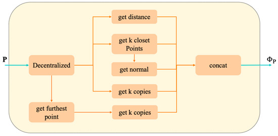
Figure 16.
Point structure extractor of the DeepMerge.
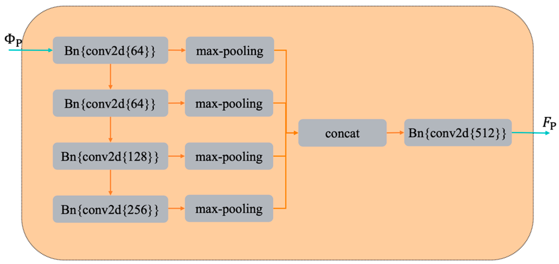
As shown in Figure 17, since the input point structure is a matrix, after each convolution, we used the max-pooling layer to compress the intermediate feature embeddings into a 1D vector, stitch all the compressed 1D intermediate feature embeddings in the last layer, and input them into the last convolution layer. The DeepMerge has five convolution layers, and the number of filters in each convolution layer is 64, 64, 128, 256, and 512.
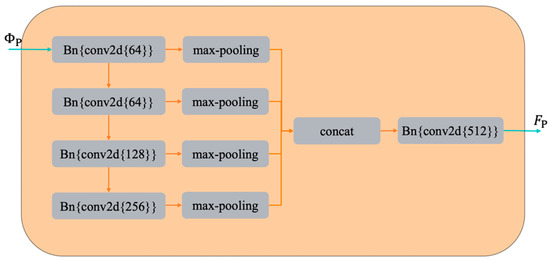
Figure 17.
Point feature extractor of DeepMerge.
After being processed by the point feature extractor, each point in the point cloud has a 512D feature embedding vector. The rotation matrix and translation vector can be obtained by feeding the point-by-point feature embedding vector into the differentiable singular value decomposition module. The rotation matrix and translation vector are the homogeneous transformation matrix stitched by adjacent point clouds.
5. Point Cloud Data Collection and Stitching Experiment
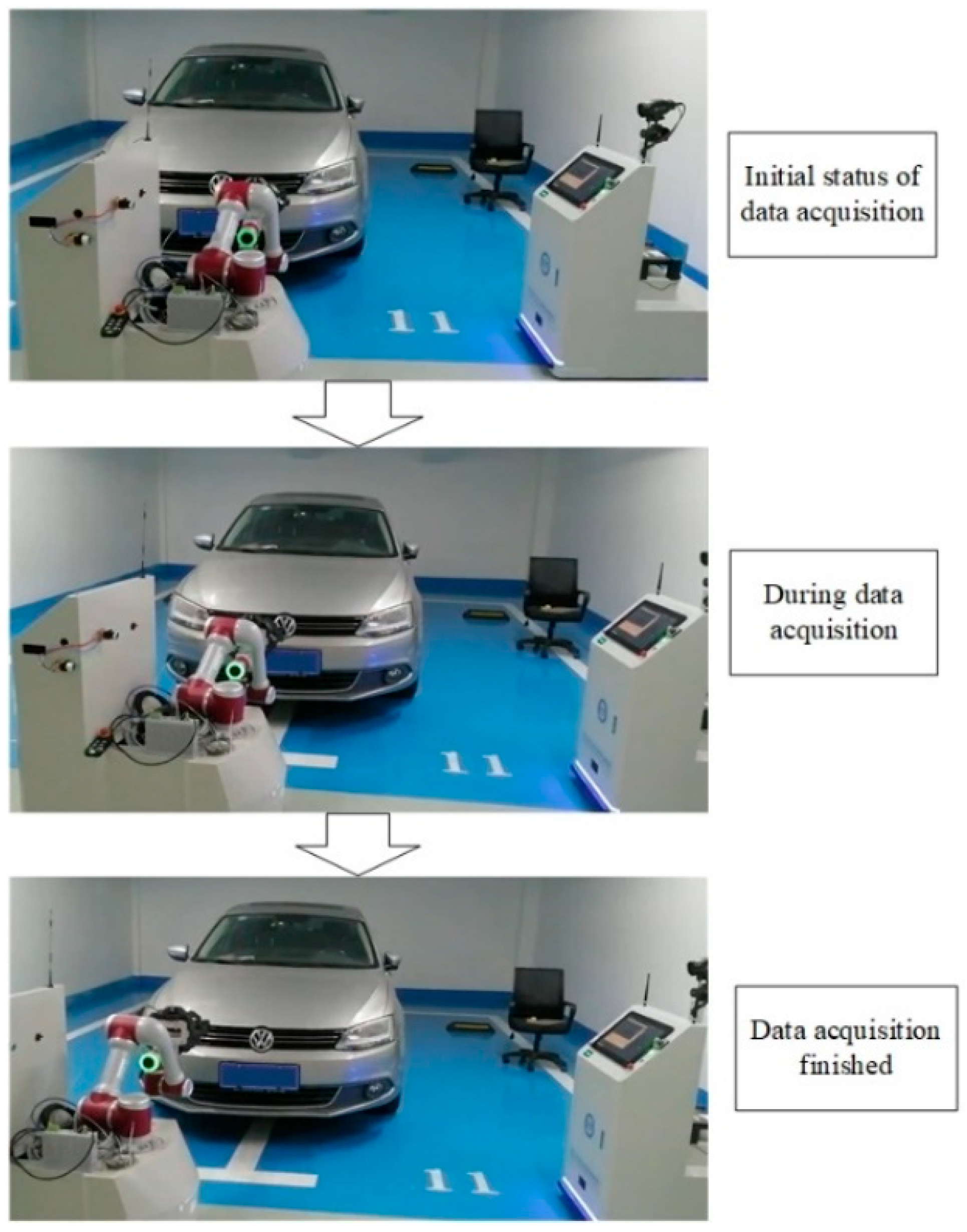
To verify the validity of the measurement system and method, this study took the vehicle nose as the object to carry out the collaborative measurement experiment.
5.1. Introduction to the Experimental Platform
As shown in Figure 18, the optical scanning measuring robot adopts the JAKA flexible manipulator. The end of the manipulator carried a high-precision binocular depth camera with a target installed on it. The camera was equipped with PhoXi 3D Scanner S with 3.2 million 3D points in each one, an accuracy of less than 0.05 mm, and an optimal scanning distance of 442 mm. The visual tracking robot took Metronor’s Lightpen as monocular cameras for tracking targets, enabling accurate measurements of up to 30 m and spatial length measurement accuracy of up to 25 μm. The above hardware ensures the accuracy of the system.
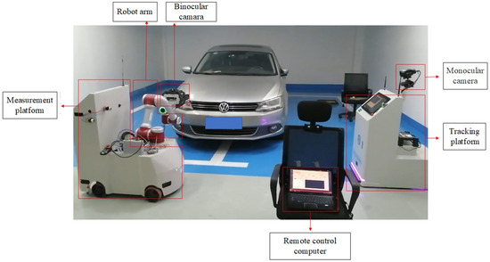
Figure 18.
Establishment of the experimental platform for data acquisition of the vehicle nose.
Additionally, the system was equipped with a remote PC terminal as the host computer to control the entire large-scale mobile robot measurement system to carry out the measurement.
5.2. Data Collection Experiment
We conducted trajectory planning for the dimensions of the vehicle nose. Specifically, we controlled the coordinated motion of the optical measurement robot and the visual tracking robot to plan a suitable data acquisition path. During data acquisition, we completed the acquisition of multi-directional point cloud data based on the planned data acquisition path. With the help of visual tracking, we unified the measurement data obtained in different poses into the world coordinate system and transfered them to the central control system to form a complete point cloud data file to finish the point cloud data acquisition.
The 3D data acquisition process (as shown in Figure 19) of the vehicle body by the dual mobile robot realizes the measurement data acquisition without sticking coded targets.
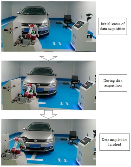
Figure 19.
Collaborative measurement data collection process.
Figure 20 shows the initial point cloud stitching completed when collecting the measurement data of the vehicle nose. The scanned point cloud data was stitched to reconstruct the complete 3D point cloud data on the surface of the vehicle nose.
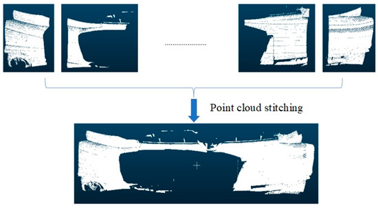
Figure 20.
Complete initial point cloud stitching of the vehicle nose.
5.3. Data Stitching Experiment
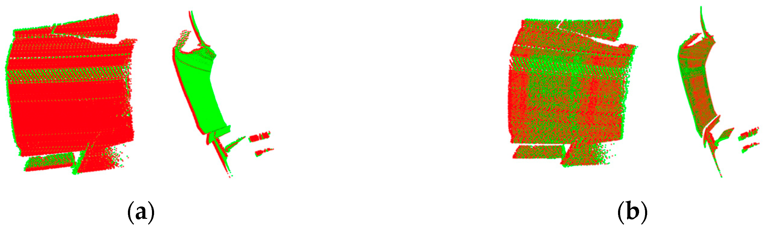
The measurement data of large-scale components needed to be collected multiple times, which means that data stitching needed to be performed many times, so each high-precision stitching is particularly important. In terms of the stitching of the vehicle nose’s complete point cloud data, the effects of the initial point cloud stitching and DeepMerge stitching correction were compared, as shown in Figure 21. The red and green points are the parts of the source point cloud (P) and the target point cloud (Q) with the same shape. Figure 21a shows the initial point cloud stitching effect of the target system. It is found that the stitching parts of the green and redpoint clouds are relatively sparse, with obvious cumulative errors. Figure 21b shows the stitching effect after the correction of the DeepMerge. It can be seen that the stitching parts of the two-point clouds overlap densely and cross evenly, indicating that a better stitching effect is achieved after the correction.
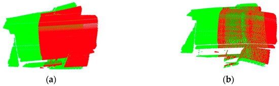
Figure 21.
Comparison of the overall stitching effect of the vehicle nose. (a) Initial point cloud stitching. (b) DeepMerge algorithm correction.
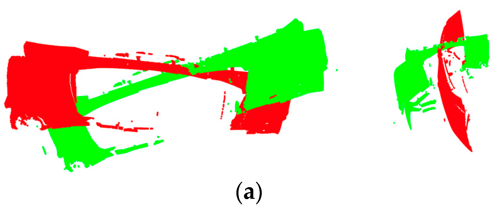
The data were collected and stitched twice at the same position on the vehicle nose in the same robot pose, as shown in Figure 22. The red and green points are the parts of the source point cloud (P) and the target point cloud (Q) with the same shape. As the two-point clouds are at the same location, they share an overlapping part, and the essence of stitching is the registration of two-point clouds. Figure 22a is the initial point cloud stitching of the target, with obvious errors; Figure 22b shows the stitching effect after the correction of the DeepMerge. The overlapping part is dense and uniform, which can achieve a better stitching effect.
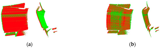
Figure 22.
Comparison of the effect of one stitching at the same position. (a) Initial point cloud stitching. (b) DeepMerge algorithm correction.
After stitching and merging the data several times, the complete 3D point cloud of the vehicle nose after being stitched by DeepMerge is shown in Figure 23. Even though there is a lot of noise, DeepMerge achieves the accurate stitching.

Figure 23.
The complete 3D point cloud of the stitched vehicle nose.
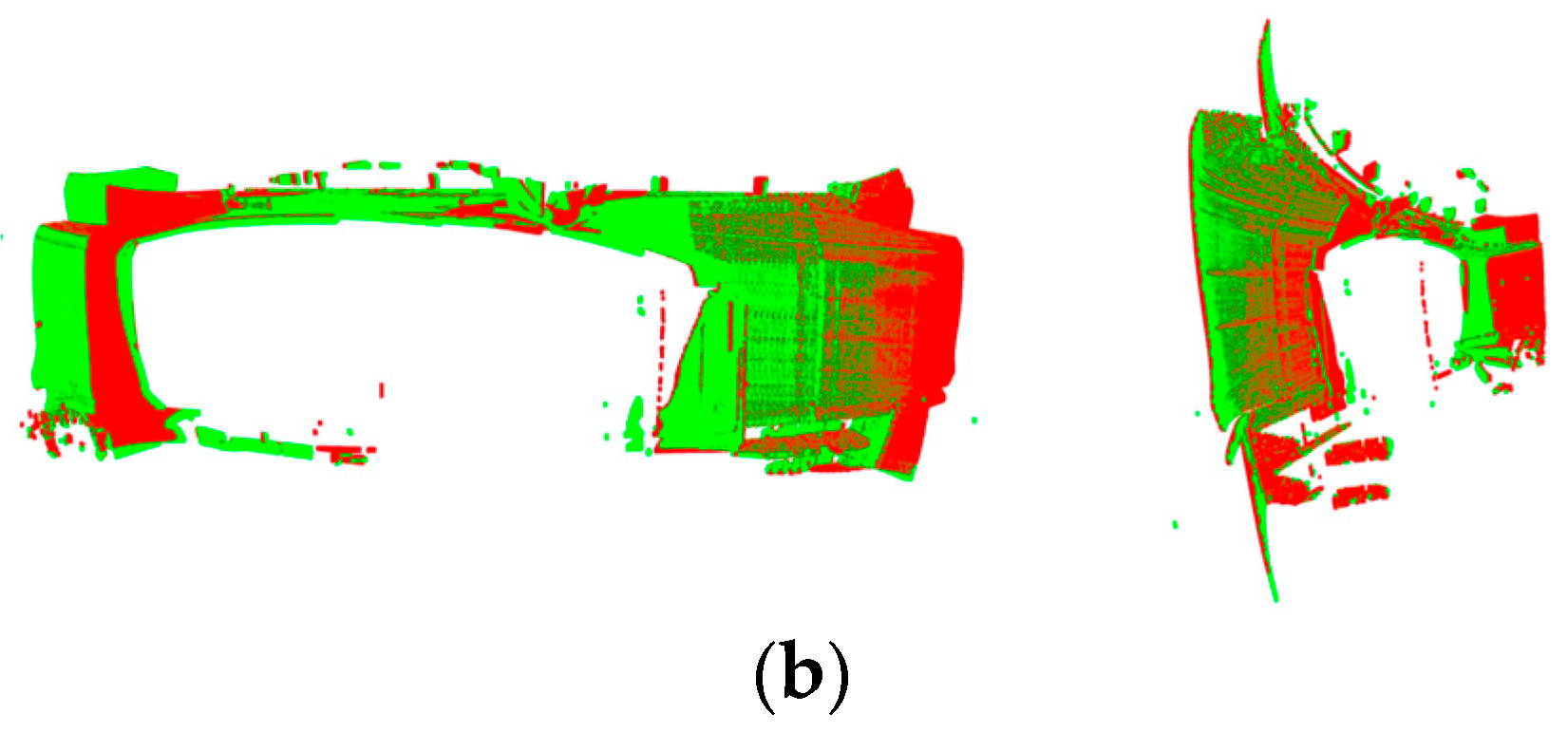
In order to verify the reliability of this experiment, this paper spliced two different complete point clouds of the vehicle head processed by the DeepMerge algorithm at any error angle, and detected whether there were errors. As shown in Figure 24, it can be seen that the two-point clouds almost reach the same pose, and the overlapping parts are dense and uniform, forming a good stitching and registration effect.


Figure 24.
Effect of DeepMerge on point cloud stitching and registration with arbitrary error. (a) The input of arbitrary errors. (b) The output of the stitching algorithm.
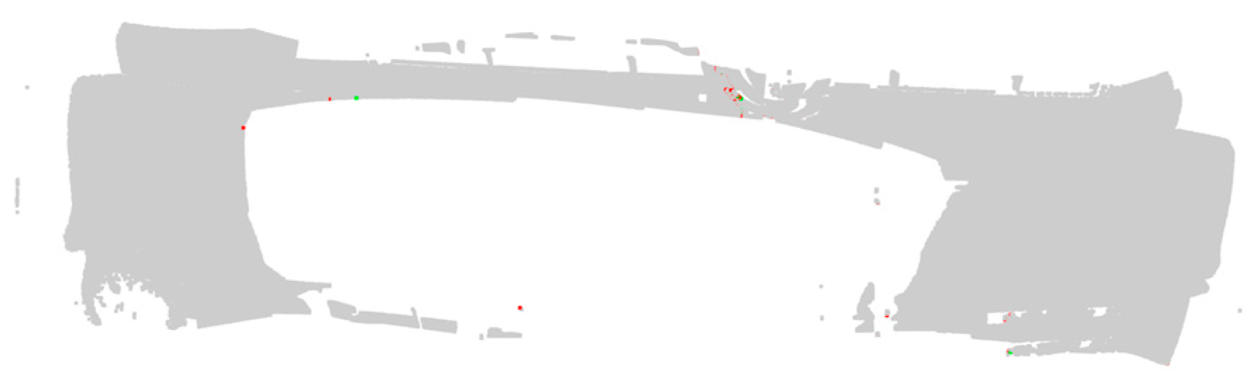
The stitching error detection was performed on the stitching and registration of the above-mentioned point cloud of the vehicle nose. Outliers were not removed during the point cloud stitching, so when performing the comparison to detect errors, some outliers were identified as errors, even if threshold screening was adopted. Figure 25 shows the error results obtained through comparison, in which the red dots denote the points with upper deviation, and the green dots denote the points that have lower deviation. It is found that the error is small, evidencing the correctness and effectiveness of this algorithm.
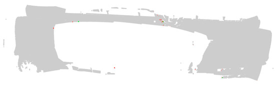
Figure 25.
Display of upper deviation and lower deviation obtained by error detection.
6. Conclusions
This paper introduced a new cooperative measurement method of two mobile robots and completed the preliminary test to evaluate the correctness of the measurement system.
In this document, the composition and design of the dual Mobile Robot Cooperative measurement system were introduced in detail, with emphasis on the system workflow and data acquisition algorithm, and a preliminary test was carried out. The new measurement method provided the possibility of measuring the detail size of large and complex components. Compared with the traditional measurement method, our method offered a great improvement. For example, using mobile vision for tracking and positioning, lifting the range limitation of the traditional fixed vision system, and realizing large-scale point cloud data collection without coding positioning marks. The preliminary test results show that the point cloud data collected and stitched by this method is dense and uniform, and the error between different collections is small, forming a good stitching and registration effect, which proves the correctness and effectiveness of this measurement method. This research method provides an effective solution for the high-precision automatic measurement of large-scale complex components.
Finally, we would like to point out that the dual robot measurement system proposed has high efficiency and low cost, and is very suitable for quality control, reverse engineering and manufacturing defect detection of large and complex components. Our future work will focus on the further improvement of the system accuracy and robustness to improve the system efficiency and measurement accuracy. In addition, this research will also be applied to the measurement of high-speed railway locomotive, aircraft, and other large parts and complete machines, which can provide ideas for the flexible measurement of large and complex parts.
Author Contributions
Conceptualization, L.Q., Z.G., J.R. and F.W.; methodology, L.Q., F.W. and H.S.; software, F.W. and H.S.; validation, F.W., Z.M. and H.S.; formal analysis, L.Q., J.R. and Z.M.; investigation, J.R., F.W. and H.S.; resources, L.Q. and Z.G.; data curation, L.Q. and F.W.; writing—original draft preparation, L.Q., J.R. and F.W.; writing—review and editing, L.Q., J.R., Z.M. and H.S.; visualization, F.W. and Z.M.; supervision, Z.G. and Y.S.; project administration, L.Q.; funding acquisition, L.Q. and Z.G. All authors have read and agreed to the published version of the manuscript.
Funding
1. The National Key Research and Development Program (Grant No. SQ2020YFF0403429); 2. Shanghai Municipal Science and Technology Major Project (No. 2021SHZDZX0103); 3. Natural Science Foundation of Jiangxi Province (20212BAB202026).
Institutional Review Board Statement
Not applicable.
Informed Consent Statement
Not applicable.
Data Availability Statement
Not applicable.
Acknowledgments
This work was supported by the Shanghai Engineering Research Center of AI & Robotics, Fudan University, China, and the Engineering Research Center of AI & Robotics, Ministry of Education, China.
Conflicts of Interest
The authors declare no conflict of interest.
References
- Zhu, D.H.; Feng, X.Z.; Xu, X.H.; Yang, Z.Y.; Li, W.L.; Yan, S.J.; Ding, H. Robotic grinding of complex components: A step towards efficient and intelligent machining challenges, solutions, and applications. Robot. Comput. Integr. Manuf. 2020, 65, 101908. [Google Scholar] [CrossRef]
- Saadat, M.; Cretin, L. Measurement systems for large aerospace components. Sens. Rev. 2002, 22, 199–206. [Google Scholar] [CrossRef]
- Feng, F.; Yan, S.J.; Ding, H. Design and research of multi-robot collaborative polishing system for large wind turbine blades. Robot. Tech. Appl. 2018, 5, 16–24. [Google Scholar]
- Dai, S.J.; Wang, X.J.; Zhang, H.B.; Wen, B.R. Research on variation of grinding temperature of wind turbine blade robotic grinding. Proc. Inst. Mech. Eng. Part B J. Eng. Manuf. 2020, 235, 367–377. [Google Scholar] [CrossRef]
- Soori, M.; Asmael, M.; Khan, A.; Farouk, N. Minimization of surface roughness in 5-axis milling of turbine blades. Mech. Based Des. Struct. Mach. 2021, 1–18. [Google Scholar] [CrossRef]
- Chen, Z.; Du, F. Measuring principle and uncertainty analysis of a large volume measurement network based on the combination of iGPS and portable scanner. Measurement 2017, 104, 263–277. [Google Scholar] [CrossRef]
- Lu, Q.; Ge, Y.H.; Cui, Z. Research on Feature Edge Detection Method of Large-Size Components Based on Machine Vision. Appl. Mech. Mater. 2012, 152–154, 1367–1372. [Google Scholar] [CrossRef]
- Xu, J.; Sheng, H.; Zhang, S.; Tan, J.; Deng, J. Surface accuracy optimization of mechanical parts with multiple circular holes for additive manufacturing based on triangular fuzzy number. Front. Mech. Eng. 2021, 16, 133–150. [Google Scholar] [CrossRef]
- Chen, Z.; Zhang, F.; Qu, X.; Liang, B. Fast Measurement and Reconstruction of Large Workpieces with Freeform Surfaces by Combining Local Scanning and Global Position Data. Sensors 2015, 15, 14328–14344. [Google Scholar] [CrossRef] [Green Version]
- Summers, A.; Wang, Q.; Brady, N.; Holden, R. Investigating the measurement of offshore wind turbine blades using coherent laser radar. Robot. Comput. Manuf. 2016, 41, 43–52. [Google Scholar] [CrossRef] [Green Version]
- Hall-Holt, O.; Rusinkiewicz, S. Stripe boundary codes for real-time structured-light range scanning of moving objects. In Proceedings of the Eighth IEEE International Conference on Computer Vision, Vancouver, BC, Canada, 7–14 July 2001; Volume 2, pp. 359–366. [Google Scholar] [CrossRef] [Green Version]
- Salvi, J.; Fernandez, S.; Pribanic, T.; Llado, X. A state of the art in structured light patterns for surface profilometry. Pattern Recognit. 2010, 43, 2666–2680. [Google Scholar] [CrossRef]
- Sadaoui, S.E.; Phan, N. Touch Probe Measurement in Dimensional Metrology: A Review. Int. J. Automot. Mech. Eng. 2021, 18, 8647–8657. [Google Scholar] [CrossRef]
- Arenhart, R.S.; Pizzolato, M.; Menin, P.L.; Hoch, L. Devices for Interim Check of Coordinate Measuring Machines: A Systematic Review. MAPAN 2021, 36, 157–173. [Google Scholar] [CrossRef]
- Reich, C.; Ritter, R.; Thesing, J. 3-D shape measurement of complex objects by combining photogrammetry and fringe projection. Opt. Eng. 2000, 39, 224–232. [Google Scholar] [CrossRef] [Green Version]
- Tam, G.K.; Cheng, Z.-Q.; Lai, Y.-K.; Langbein, F.C.; Liu, Y.; Marshall, D.; Martin, R.R.; Sun, X.-F.; Rosin, P.L. Registration of 3D Point Clouds and Meshes: A Survey from Rigid to Nonrigid. IEEE Trans. Vis. Comput. Graph. 2012, 19, 1199–1217. [Google Scholar] [CrossRef] [PubMed] [Green Version]
- Yin, S.; Ren, Y.; Guo, Y.; Zhu, J.; Yang, S.; Ye, S. Development and calibration of an integrated 3D scanning system for high-accuracy large-scale metrology. Measurement 2014, 54, 65–76. [Google Scholar] [CrossRef]
- Barone, S.; Paoli, A.; Razionale, A.V. 3D Reconstruction and Restoration Monitoring of Sculptural Artworks by a Multi-Sensor Framework. Sensors 2012, 12, 16785–16801. [Google Scholar] [CrossRef] [Green Version]
- Yang, S.; Liu, M.; Yin, S.; Guo, Y.; Ren, Y.; Zhu, J. An improved method for location of concentric circles in vision measurement. Measurement 2017, 100, 243–251. [Google Scholar] [CrossRef]
- Yang, S.; Liu, M.; Song, J.; Yin, S.; Guo, Y.; Ren, Y.; Zhu, J. Flexible digital projector calibration method based on per-pixel distortion measurement and correction. Opt. Lasers Eng. 2017, 92, 29–38. [Google Scholar] [CrossRef]
- Paoli, A.; Razionale, A.V. Large yacht hull measurement by integrating optical scanning with mechanical tracking-based methodologies. Robot. Comput. Manuf. 2012, 28, 592–601. [Google Scholar] [CrossRef]
- Barone, S.; Paoli, A.; Razionale, A.V. Shape measurement by a multi-view methodology based on the remote tracking of a 3D optical scanner. Opt. Lasers Eng. 2012, 50, 380–390. [Google Scholar] [CrossRef]
- Gan, Z.X.; Tang, Q. Laser sensor-based robot visual system and its application. Robot. Tech. Appl. 2010, 5, 20–25. [Google Scholar]
- Mosqueira, G.; Apetz, J.; Santos, K.; Villani, E.; Suterio, R.; Trabasso, L.G. Analysis of the indoor GPS system as feedback for the robotic alignment of fuselages using laser radar measurements as comparison. Robot. Comput. Manuf. 2012, 28, 700–709. [Google Scholar] [CrossRef]
- Jung, M.; Song, J.B. Efficient autonomous global localization for service robots using dual laser scanners and rotational motion. Int. J. Control Autom. Syst. 2017, 15, 723–751. [Google Scholar] [CrossRef]
- Wang, Z.; Mastrogiacomo, L.; Franceschini, F.; Maropoulos, P. Experimental comparison of dynamic tracking performance of iGPS and laser tracker. Int. J. Adv. Manuf. Technol. 2011, 56, 205–213. [Google Scholar] [CrossRef] [Green Version]
- Michalos, G.; Makris, S.; Eytan, A.; Matthaiakis, S.; Chryssolouris, G. Robot Path Correction Using Stereo Vision System. Procedia CIRP 2012, 3, 352–357. [Google Scholar] [CrossRef] [Green Version]
- Schmidt, B.; Wang, L. Automatic work objects calibration via a global–local camera system. Robot. Comput. Manuf. 2014, 30, 678–683. [Google Scholar] [CrossRef]
- Wang, J.; Tao, B.; Gong, Z.; Yu, S.; Yin, Z. A Mobile Robotic Measurement System for Large-scale Complex Components Based on Optical Scanning and Visual Tracking. Robot. Comput.-Integr. Manuf. 2021, 67, 102010. [Google Scholar] [CrossRef]
- Wang, J.; Tao, B.; Gong, Z.; Yu, W.; Yin, Z. A Mobile Robotic 3-D Measurement Method Based on Point Clouds Alignment for Large-Scale Complex Surfaces. IEEE Trans. Instrum. Meas. 2021, 70, 7503011. [Google Scholar] [CrossRef]
- Lindner, L.; Sergiyenko, O.; Rodríguez-Quiñonez, J.; Tyrsa, V.V.; Mercorelli, P.; Fuentes, W.F.; Murrieta-Rico, F.N.; Nieto-Hipólito, J. Continuous 3D scanning mode using servomotors instead of stepping motors in dynamic laser triangulation. In Proceedings of the 2015 IEEE 24th International Symposium on Industrial Electronics (ISIE), Buzios, Brazil, 3–5 June 2015; pp. 944–949. [Google Scholar]
- Garcia-Cruz, X.M.; Sergiyenko, O.; Tyrsa, V.V.; Rivas-López, M.; Hernández-Balbuena, D.; Rodríguez-Quiñonez, J.; Basaca-Preciado, L.; Mercorelli, P. Optimization of 3D laser scanning speed by use of combined variable step. Opt. Lasers Eng. 2014, 54, 141–151. [Google Scholar] [CrossRef]


Publisher’s Note: MDPI stays neutral with regard to jurisdictional claims in published maps and institutional affiliations. |
© 2022 by the authors. Licensee MDPI, Basel, Switzerland. This article is an open access article distributed under the terms and conditions of the Creative Commons Attribution (CC BY) license (https://creativecommons.org/licenses/by/4.0/).