Article

Thermal Field and Stress Analysis of Induction Motor with Stator Inter-Turn Fault

School of Electrical and Electronic Engineering, Harbin University of Science and Technology, Harbin 150080, China
*
Author to whom correspondence should be addressed.
Machines 2022, 10(7), 504; https://doi.org/10.3390/machines10070504
Submission received: 15 May 2022 / Revised: 18 June 2022 / Accepted: 22 June 2022 / Published: 23 June 2022

Abstract

:
Inter-turn fault (ITF), a typical motor fault, results in significant variations in the thermal characteristics of a motor. For fault, temperature rise (TR) experiments and thermal field-stress field simulations of an induction motor are carried out to reveal the fault characteristics related to ITF. First, based on the actual structure and the cooling type of the motor, a whole-domain simulation model of the fault thermal field was established. The reasonable equivalence of the motor and the calculation of the heat transfer boundaries were conducted during the modeling process. Then, the three-dimensional transient thermal field under a rated load before and after the fault was obtained, and the accuracy of the simulation could be validated through the comparison of the measured TR at several temperature-measuring points. The heat-transfer law and the notable thermal characteristics of the fault can be presented by analyzing the simulated and measured temperature data. In addition, a fault feature is proposed to provide a reference for diagnosis using the temperature difference of winding at different positions at different moments. Finally, the rotor thermal stress distribution of the normal and faulty motor is obtained by thermal-stress-coupled calculation, which can be used to evaluate the possibility of rotor fault caused by ITF.

1. Introduction

Due to their simple structure and low manufacturing cost, induction motors are widely used in industrial and social applications in fans, pumps, belts, compressors, electric vehicles, etc. The complex operating conditions of these motors can easily lead to various faults in them. Inter-turn fault (ITF) is the most common type of stator fault in AC motors, accounting for about 28–36% of total faults [1]. The overheating caused by the fault will accelerate the aging of the insulation and further deepen the degree of the fault [2].
The thermal field of different motors with ITF has been studied [3,4,5,6,7,8,9]. The variations in magnetic field and loss after the ITF in a permanent magnet synchronous motor (PMSM) are analyzed in [3]. The distribution of the motor thermal field with different degrees of fault is given by a two-dimensional (2D) finite-element (FE) simulation, and the housing temperature in the normal condition is measured by an infrared imager. In [4], the faulty thermal field of an induction motor, considering different contact-resistance conditions, is simulated by a 2D lumped parameter (LP) model and an FE model. On this basis, a 2D thermal field distribution of an induction motor with ITF under the voltage imbalance is considered [5], and similar results are obtained. However, due to the difference between the actual structure of the motor and the axial heat dissipation conditions, the 2D simulation results reported in [3,4,5] cannot reflect the accurate faulty thermal field distribution, and the above research lacks adequate experimental verification.
The rotor thermal field of a synchronous generator under rotor static eccentricity fault, ITF, and the combined fault are studied in [6]. The changes in rotor loss and rotor three-dimensional (3D) magnetic field before and after the fault are given. The rotor thermal distribution in each case is obtained through 3D electromagnetic–thermal coupled simulation, and the results are verified by rotor temperature measurement. A similar coupled analysis method was also adopted in [7]. The faulty thermal distribution of a permanent magnet-assisted synchronous reluctance motor is presented, considering the influence of changes in temperature and working condition on motor losses, and the correctness is verified experimentally. In addition, the research on the thermal field of the motor with ITF using the 3D LP model and the FE model also achieved good results [8,9].
The thermal stress of the rotor changes as the temperature of the rotor varies. For the rotor structure design of high-speed motors [10] and the optimal design of motors with specific rotor structures [11], thermal stress analysis has proven to be an efficient research method. In terms of the research on the thermal rotor stress caused by a fault [12] focuses on the thermal stress of a hydro generator after a rotor excitation winding fault. The rotor thermal strain and stress variations are obtained by considering the different fault turns and faulty locations. In [13], the influence of a broken bar fault on the distribution of the rotor thermal stress is analyzed, and the reason for the broken bar fault of the induction motor is presented by evaluating the maximum stress area of the rotor squirrel cage. The temperature and stress variations in the rotor squirrel cage are analyzed during the breakage development process [14]. Furthermore, the calculated stress values of each transient operation are compared with the physical failure model of the rotor to provide a fatigue analysis and lifespan evaluation of the rotor.
In general, considering the difference in heat dissipation conditions in axial and circumferential directions of the totally enclosed fan-cooled (TEFC) motor studied in this paper, the space and time distribution of the motor thermal field after the fault and the internal transient temperature rise (TR) characteristics need to be studied. In addition, due to the particularity of the squirrel cage structure, it is necessary to evaluate the influence of faults on the rotor from the perspective of thermal stress.
In this paper, the 3D transient thermal field-rotor thermal stress field simulation and the TR measurement of the embedded thermistor are used to study the influence of ITF on the thermal characteristics of the motor. The comprehensive analysis of the faulty thermal field and the thermal stress field distribution reveal the faulty thermal characteristics of the motor, which can be used as a reference for ITF research.
The advantages of this research compared with existing literature research results can be summarized as follows: (1) The adopted 3D transient simulation can reflect the transient characteristics of faults and is closer to the practice than 2D and steady-state simulation. (2) Considering the structure of the TEFC motor, both the transient and steady-state temperature characteristics of the faulty motor are analyzed, and a fault feature is proposed using the winding temperature characteristics at different moments. (3) The rotor thermal stress analysis is introduced for the first time in studying the stator ITF in induction motors, expanding the research direction and evaluating the possibility of other faults caused by ITF.

2. Prototype Parameters and Simulation Model

2.1. Parameters and Material Properties of Prototype

This paper takes a squirrel cage induction motor as the prototype. The cooling type of the motor is TEFC, and other parameters are listed in Table 1. The three-phase winding of the motor is rewound, and the A-phase is taken as the faulty phase. The different fault degrees in the winding process are considered with the number of faulty turns of 5, 15, 25, 35, and 45.
It is necessary to perform equivalent processing on some motor parts before modeling according to the prototype parameters and the motor entity. For the air-gap heat transfer model, the authors of [15] proved that the air-gap heat transfer of a small induction motor is equivalent to the heat conduction, which is reasonable and has a fairly high simulation accuracy. This paper also adopts the heat conduction form for the air-gap equivalent. In order to simplify the complex heat-exchange process in stator slots, an equivalent stator slot model is established regarding [16], and differentiated modeling was carried out according to the fault condition. Figure 1 shows the equivalent model in the stator slot under fault conditions adopted in this paper, in which the equivalent insulation can be calculated according to (1).
λ e q = i = 1 n δ i / i = 1 n δ i λ i
where λ e q is the thermal conductivity of equivalent insulation; δ i is the equivalent thickness of each insulating material; and λ i is the thermal conductivity of each insulating material.
Table 2 lists the materials of all motor parts and the material properties involved in the thermal field simulation. The silicon steel sheet used in the stator and rotor core has special thermal conductivity; its thermal conductivity is anisotropic, and that of other materials is isotropic.

2.2. Simulation Model

2.2.1. Basic Equations and Model of Thermal Field

The basic equations and boundary conditions for the calculation of the three-dimensional (3D) transient thermal field can be given by
x ( λ x T x ) + y ( λ y T y ) + z ( λ z T z ) + q v = ρ C V T t λ n T n S i = α T T f
where λ x , λ y , λ z , λ n are the thermal conductivities in x , y , z , n directions, respectively; T is the temperature of the object; ρ is the density; C V is the specific heat capacity of the object; q v is the internal heat flux density; S i is the boundary of each heat dissipation surface; n is the normal vector of each boundary surface; α is the heat transfer coefficient in n direction; and T f is the temperature of the medium.
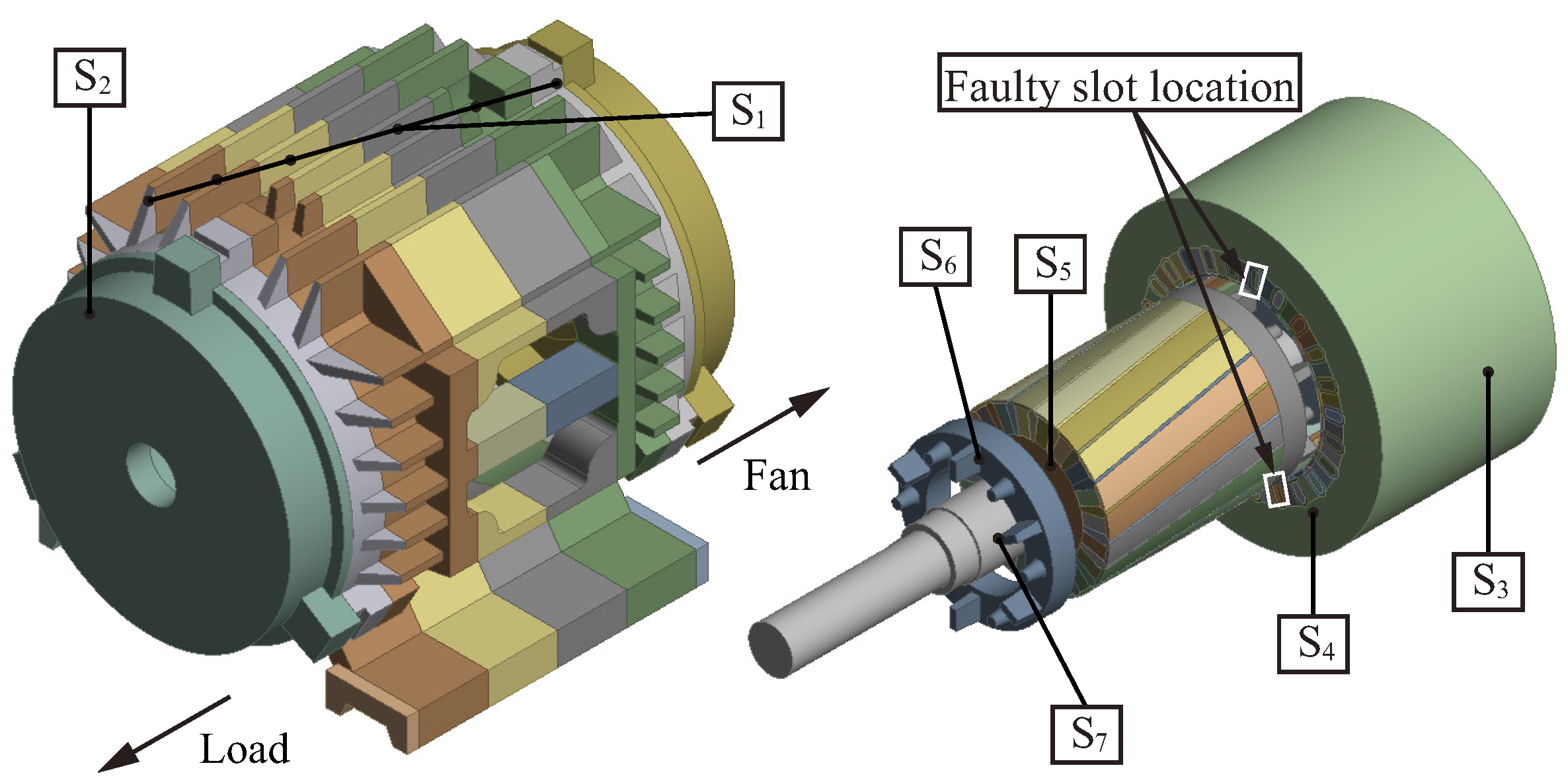
The 3D thermal field simulation model of the motor is presented in Figure 2. In the modeling process, the structure of each heat dissipation fin and junction box of the housing is consistent with the prototype, ignoring some connecting and fixing holes that have little influence on the thermal field. Considering the difference in axial heat dissipation conditions, the housing is divided into six parts in the axial direction. Fans and balance weights of the rotor end-ring increase the heat dissipation area, which is considered in the rotor modeling. The winding and insulation in the stator slot are modeled according to the equivalent model in Figure 1. Due to the heat transfer of the motor being concentrated in the effective axial part of the core, the winding ends are ignored to simplify the model complexity and shorten the calculation time, and the winding end faces are set as adiabatic surfaces.
Two heat transfer modes are considered in the model: the mode of each motor component contact part is heat conduction, and the rest is the convection heat transfer (the heat dissipation surfaces are shown in S 1 S 7 ). The material properties in Table 2 are assigned to each part of the motor, and the heat dissipation coefficients of S 1 S 7 in the model are calculated, respectively, to complete the establishment of the temperature field calculation model.

2.2.2. Heat Dissipation Boundaries

Table 3 lists the calculation formulas and values of the heat dissipation coefficient at each boundary surface ( S 1 S 7 in Figure 2), and the coefficient calculation method is based on [17,18]. As the fan will cause uneven axial wind velocity of the housing, the heat dissipation coefficient of each section of the housing surface needs to be calibrated with the measured wind velocity. Using the anemometer to measure the wind velocity at each position of S 1 in Figure 2 at room temperature, one substitutes the formula to calibrate the corresponding heat dissipation coefficient, assuming that the heat dissipation conditions of each section are consistent in the circumferential direction. In addition, other heat dissipation surface coefficients can be calculated by substituting the actual velocity of the motor. It should be noted that there is an interfacial gap between the stator core and the housing, which will reduce the heat conduction. In the modeling, it is assumed that the equivalent conduction of thermal resistance at this position is equal to the equivalent heat transfer resistance, and the heat dissipation coefficient is assigned to S 3 to deal with this problem. From the calculation formula of S 3 , it can be seen that the heat dissipation coefficient of S 3 is related to the actual length of the air-gap between the stator core and the housing. On the premise that the thermal conductivity coefficient δ 0 is determined, the air-gap length is often taken as an empirical value.
After the boundary conditions of the model are determined, the loss values of each part of the motor are loaded into each area of the motor as the heat source to calculate the 3D transient thermal field distribution. The accuracy of the calculation results can be verified with a TR experiment on the motor (as shown in Section 5.1).

3. Experimental Platform

In the research in the motor ITF thermal field, it is necessary to measure the TR at key parts of the motor. During the rewinding process, temperature-measuring elements are embedded inside the motor in the middle of the axial direction. The positions of each temperature-measuring point (TMP) are shown in Figure 3 (S1–S24 are the numbers of stator slots).
TMP-A is located in the middle of the faulty slot winding; TMP-B is located in the middle of the non-faulty slot winding in the faulty phase; TMP-C and -D are, respectively, located in the middle of the non-faulty phase winding on the side and opposite side of the junction box; TMP-E and -F are located at the bottom of stator core slot at the same position of TMP-C and -D; TMP-G and -H are located in the air-gap on the side and opposite side of the junction box, and these two detectors are placed in the stator slot wedge at the air-gap side during the embedding process.
The thermal field variation of the TEFC motor caused by ITF remains to be studied. Thus, this paper does not consider the influence of different fault degrees and carries out the TR experiment of normal and faulty motors under a single fault degree. The TR experimental platform of the normal and 45-turn faulty motor under rated load conditions is shown in Figure 4. The voltage regulator and magnetic brake are used to maintain the stability of the supply and load. The power analyzer (HIOKI 3196, Sampling rate: 200 kS/s, 2 MS/s; Accuracy: ±0.2% rdg ± 0.1% f.s. for voltage, ±0.3% rdg ± 0.01% f.s. for current) is equipped with voltage (HIOKI 9438, Input impedance: 4 M Ω ; Maximum voltage: 600 Vrms CAT III ), and current detectors (HIOKI 9661, Maximum current: 500 Arms; Frequency range: 40 Hz–5 kHz) to monitor the electrical signals. The real-time temperature measurement for each TMP is conducted through electronic thermometers (TM902C, Resolution: 0.1 °C; Accuracy: ±0.75 °C; Range: −50–750 °C) with K-type detectors (TP-01, Accuracy: ±0.5 °C; Range: −50–400 °C, Thermal response time: 1 s). In order to ensure the safety of the prototype and experimental equipment, two short-circuit (SC) turns are connected through a contact resistance to limit the excessive SC current.

4. Heat Source Analysis

The heat source is the loss of each motor part during operation, and the total loss of the motor consists of winding copper loss, core loss, rotor aluminum loss, and mechanical and stray loss.
P T o t a l = P C u + P F e + P A l + P Δ
where P T o t a l is the total loss; P C u is winding copper loss; P F e is core loss; P A l is rotor aluminum loss; and P Δ is mechanical and stray loss.
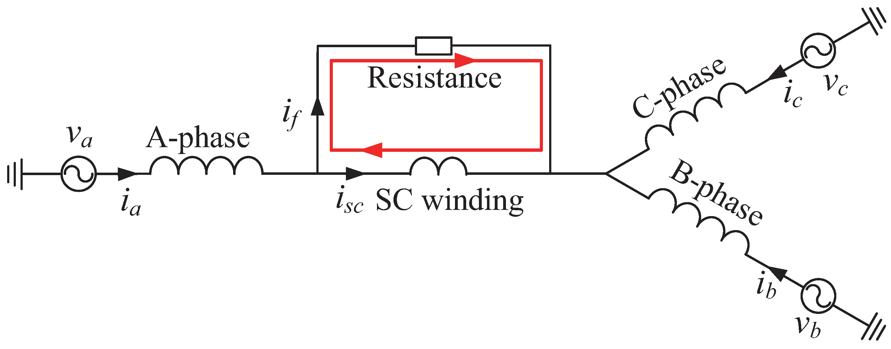
Copper loss and stray loss are calculated through experimental values and empirical formulas. The electromagnetic simulation calculates core loss and rotor aluminum loss, and specific calculation methods can be found in [17]. For a normal three-phase winding motor, the resistance and current of each phase are equal, and the copper loss can be calculated by P C u = 3 I P 2 R ( I P is the effective value of the phase current and R is the value of phase resistance). The equivalent circuit topology of the motor is changed by ITF, as shown in Figure 5, and an SC current is appended in addition to the original equal three-phase current. In the case of the fault, the copper loss of the motor can be calculated according to (4). Table 4 lists the copper loss values under normal and 45-turn fault conditions at 75 °C as a reference. It can be seen that the total copper loss of the motor increases significantly and that the copper loss of each phase winding varies greatly after the fault.
P C u = I A 2 R R s c + I B 2 R + I C 2 R + I s c 2 R s c
where I A , I B , and I C are the effective values of each phase current; I s c is the effective value of SC current; and R s c is the resistance of the faulty coil.
Figure 6 is the distribution of the core loss of the motor before and after the fault, and the location of the faulty slot has an obvious influence on the loss space distribution. Due to the effect of the reverse pulsed magnetic field generated by the SC current, one side of the faulty slot will be magnetized, and the other one will be demagnetized [19]. As indicated by the marks in the figure, the core loss of the teeth on both sides of the faulty slot is quite different, which further increases the non-uniformity of the distribution of core loss after the fault.
Since the core loss of the rotor is small and P Δ is considered a constant, these two values will not be discussed here. The calculated loss values of each part of the motor are converted into loss densities, which are loaded as the heat sources to the corresponding position of the thermal field model. Thus, the thermal field distribution before and after the fault can be obtained by simulation.

5. Thermal Field Analysis

Three-dimensional thermal field simulation and TR experiments are carried out for normal and faulty motors under rated load conditions. The temperature distribution law of the motor before and after the fault and the influence on the spatial and temporal thermal characteristics can be obtained.

5.1. Thermal Field Distribution before and after Fault

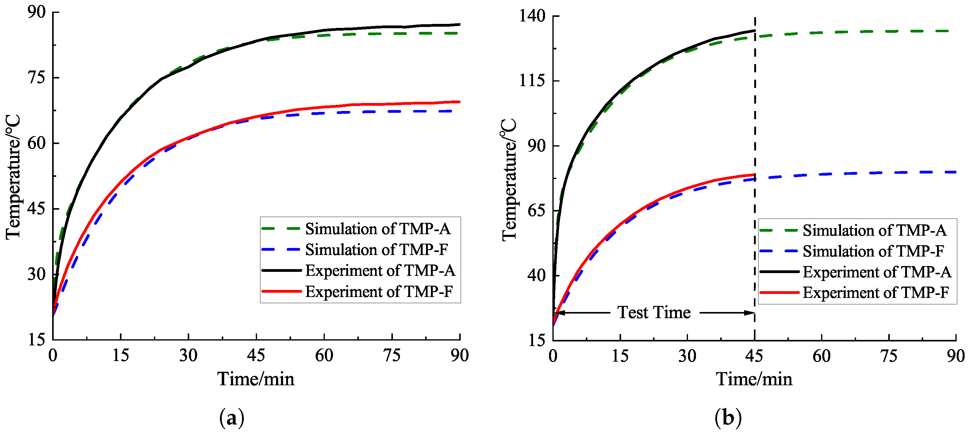
Figure 7 shows the simulated and measured temperature curves of the two test points (TMP-A and -F) of normal and faulty motors. It can be seen that the trend and temperature value of the simulation curves are similar to the measured ones, indicating that the accuracy of modeling and simulation is high. It should be noted that during the rated load fault test, the measured TR of the faulty slot winding reached 112.8 K (the test had been operating for 45 min), exceeding the maximum TR limit of insulation class F. In order to ensure the safety of the equipment, the test is stopped immediately. Unless otherwise specified, the steady-state temperatures of the normal and faulty motor are the ones at 90 min and 45 min, respectively.
The steady-state temperature and TR values before and after the fault of each TMP of the motor are listed in Table 5, and the TR of each TMP of the motor is quite different. In the normal motor, due to the poor heat-dissipation conditions at the junction box position, the TR at TMP-C is higher than that at TMP-A, -B, and -D of other windings. The TRs of TMP-E and -G at the slot bottom and the air-gap of the junction box are higher than those of TMP-F and -H on the opposite side. After the fault, the temperature of all TMPs increases noticeably, and the maximum value occurs in the faulty slot winding (TMP-A). The temperature-distribution law of other measuring points related to the position of the junction box is the same as that of the normal motor.
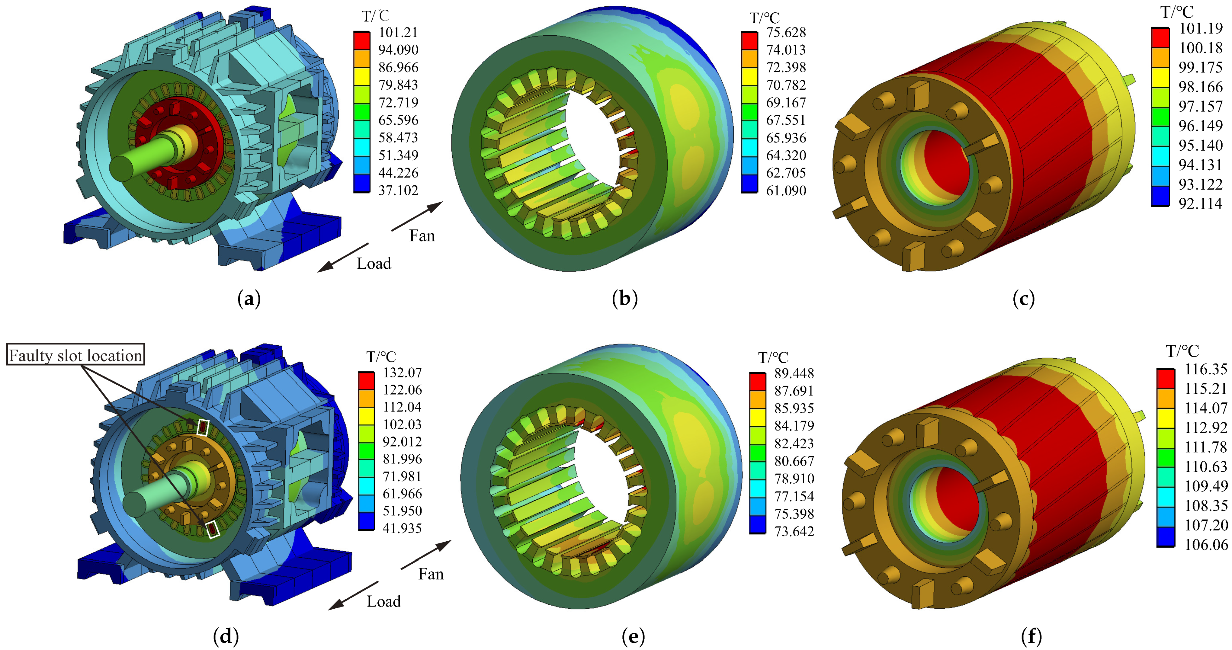
Figure 8 is the temperature distribution of the whole motor, stator core, and rotor before and after the fault. The comparison between Figure 8a,d shows that the hotspot of the normal motor is located in the rotor, and the temperature of the circumferential sections is approximately evenly distributed. The hotspot after the fault is located in the faulty winding, and the axial and circumferential distribution of housing temperature is no longer uniform, which shows that the housing temperature on the side close to the faulty slot is higher than that in other positions.
The temperature of the stator core and rotor increase after the fault, but the overall distribution law is consistent with the normal motor. Due to the different heat-dissipation conditions, the temperature of the stator core at the axial load side is higher than that at the fan side, and the temperature at the circumferential junction box side is higher than that at other positions. As for the rotor, there is a slight temperature difference in the axial direction, while the difference in the radial direction is large. The temperature on the load side is higher than on the fan side, and the hotspot is at the bar near the middle of the rotor. After the fault, the rotor temperature increases significantly, with an increase of 15.0%, which leads to the rise in thermal stress in the key position of the rotor, thus increasing the risk of rotor fault.
In general, the temperature of the housing, stator core, and rotor before and after the fault does not show new temperature distribution characteristics except for an obvious increase. Therefore, for the change in thermal field caused by ITF, one should focus on the temperature variation of winding.
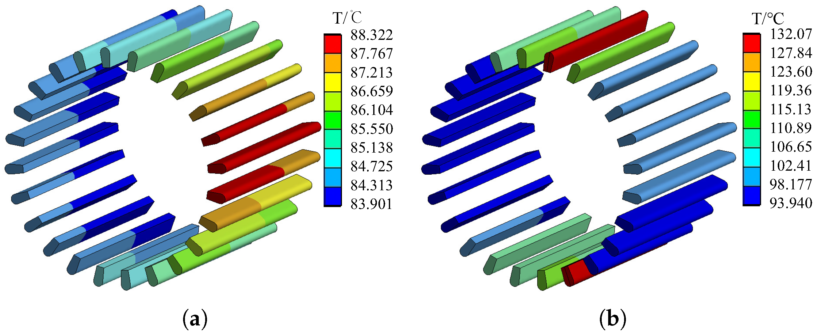
Figure 9 shows the temperature distribution of winding in the steady state before and after the fault. Under the normal condition, the hotspot appears at the junction box side, and the overall winding temperature difference is only 4.4 °C. However, the hotspot is located in the faulty slot after the fault, and the overall temperature difference in the winding reaches 38.3 °C. Furthermore, the average temperature of each phase winding is also quite different (131.4 °C in the faulty slot of the A-phase, 110.1 °C in the non-faulty slot of A-phase, 99.45 °C in the B-phase, 95.94 °C in the C-phase).

5.2. Thermal Characteristics Caused by Fault

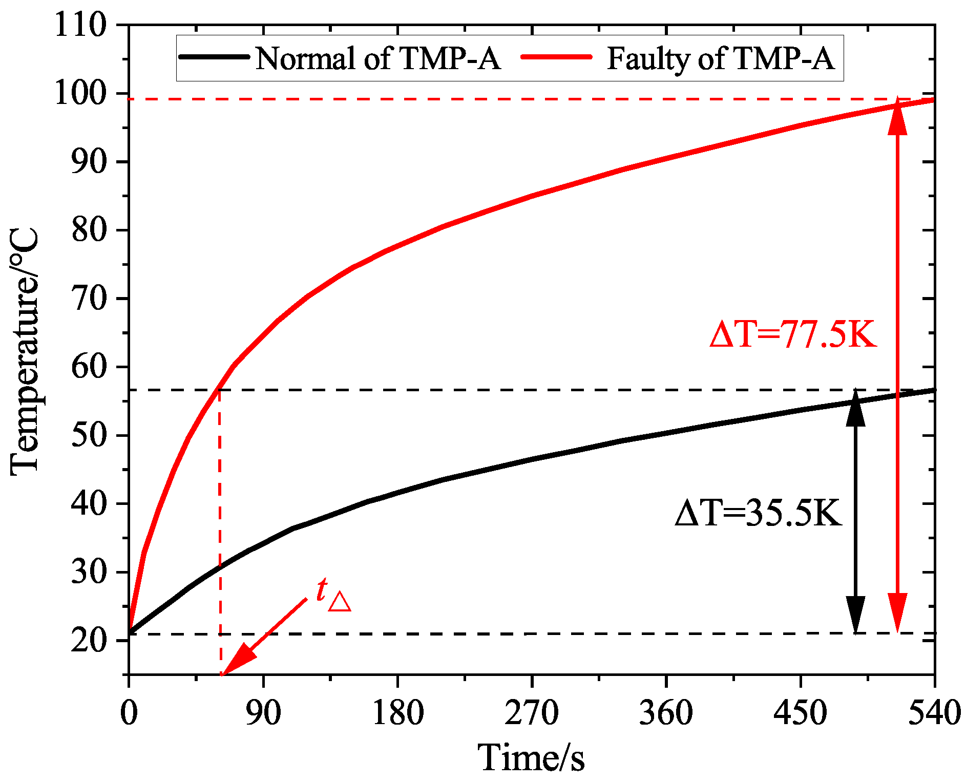
The TR of the motor is obvious in the early stage of operation after the fault, as shown in Figure 7b. In order to study the impact of the fault on the TR characteristics of the motor, the measurement data of the first nine minutes under normal and faulty conditions at TMP-A are drawn in Figure 10. The temperature of this position changes drastically after the fault, and the TR in the first nine minutes is more than twice that of the normal motor. Taking the time to reach the normal TR of the motor as the measurement standard, the TR time at this point after the fault is 88.9% shorter than the normal time.
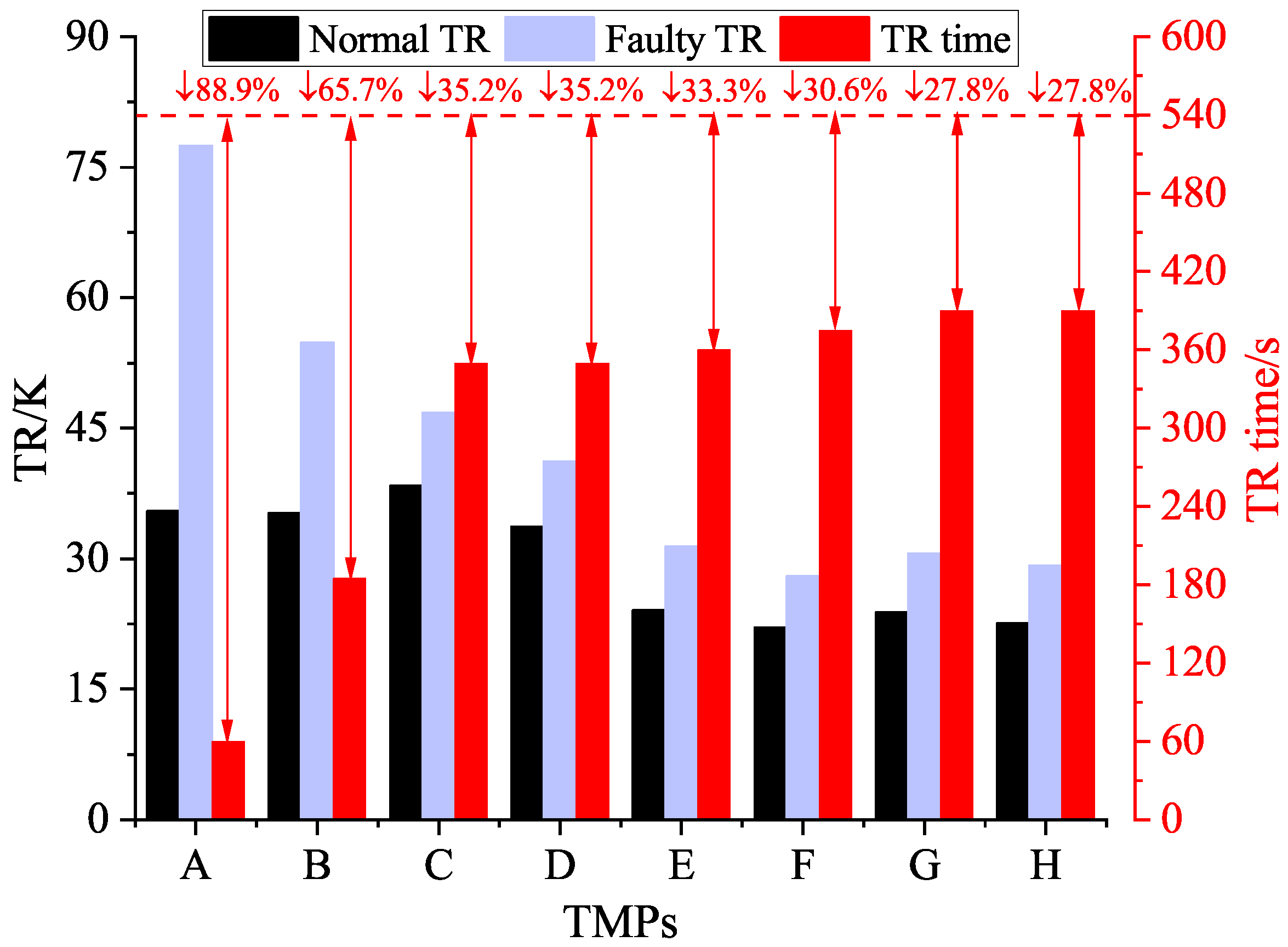
ITF will cause great changes in the heat generation rate of each part of the motor before and after the fault and then lead to a time change in TR at the same TMP, as well as overall temperature space distribution variation caused by the related position to the faulty slot. The measured TR and TR time of the first nine minutes before and after the fault of each TMP are plotted in Figure 11. The TR time of each TMP is defined as the time to reach the normal TR of the motor, and the shortening of the TR time of each point is marked in the figure. The data in the figure show that the TR of the fault phase winding is large and the TR rate is fast (TMP-A and -B), especially the faulty slot winding, while there is little difference between the TR and TR rate of TMPs at other positions. Since the TMPs are located in different parts of the motor, the difference in temperature distribution and TR time of each TMP further explains the space and time characteristics of motor temperature caused by the fault.
According to the analysis results in the previous section, the temperature characteristics of the motor housing, stator core, and rotor are not obvious after the fault; on the other hand, the part with the most drastic temperature change is the stator winding. Figure 12 shows the temperature distribution of stator winding at three different moments. The positions of each slot, phase belt, and the faulty slot are marked in the figure. It can be seen that the temperature distribution of normal motor windings is evenly distributed in the initial stage, middle stage, and steady state of operation, and the temperature difference between windings in different slots is small. The distribution of winding temperature after the fault is complex. The temperature of non-faulty phase winding shown in Figure 12a is almost the same as that of the normal motor in the initial stage of faulty operation, while the temperature of the faulty phase winding increases significantly and the temperature of the faulty slot winding is the highest. From the middle stage of faulty operation to the final moment, the winding temperature of the faulty phase continues to rise, the temperature distribution remains unchanged, and the temperature of non-faulty winding also gradually increases, which is significantly higher than the temperature of the normal motor.
In order to measure the temperature distribution of stator winding before and after fault, variance ( S 2 ) is used to evaluate the dispersion of winding temperature distribution caused by the fault. S 1 2 in Table 6 is the temperature variance of all 24 slots. Under normal conditions, the S 1 2 value is small, indicating that normal motor-winding temperature is evenly distributed, while the dispersion degree of overall winding temperature is significantly improved after the fault. The great difference in S 1 2 before and after the fault is accompanied by three moments of motor operation, indicating that this feature can be used as a thermal feature of ITF for fault diagnosis. However, it is impossible to monitor the winding temperature of all slots in practice; thus, it is measured by extracting one slot winding per phase. S 2 2 is the data that do not contain the faulty slot winding (S4, S8, S12), and S 3 2 is the data that contain the faulty slot winding (S3, S7, S11). It can be seen that the three data are extremely small under normal conditions. Even if S 2 2 does not have the faulty slot winding, the temperature also has a large deviation in the statistical data value after the fault, and this deviation is further enlarged for S 3 2 . It should be noted that the values in Table 6 only provide a reference for fault diagnosis. The specific winding monitoring mode and the definition of the fault feature need to study the changes caused by different fault degrees, which will be carried out in future research work.

6. Thermal Stress Analysis of Rotor

During the operation of the motor, the rotor TR is higher due to the weak heat dissipation capacity, and the rotor TR is further increased after the occurrence of ITF. The thermal stress caused by the rotor structure constraints and thermal expansion is one of the main causes of rotor squirrel cage fault, so it is worth exploring the change in thermal stress caused by fault and evaluating the possibility of rotor fault.

6.1. Basic Equations of Thermal Stress Calculation

According to linear thermal stress theory, the total strain of the micro-element consists of two parts: one part is caused by the temperature change, and the other part is caused by stress. Therefore, the generalized Hooke’s law, including thermal stress and thermal strain, can be obtained [20]:
ε x = 1 E σ x μ σ y + σ z + α Δ T ε y = 1 E σ y μ σ x + σ z + α Δ T ε z = 1 E σ z μ σ x + σ y + α Δ T γ x y = τ x y G , γ y z = τ y z G , γ z x = τ z x G
where ε x , ε y , ε z , γ x y , γ y z , γ z x and σ x , σ y , σ z , τ x y , τ y z , τ z x are each components of normal and shear strain, as well as normal and shear stress; E is the elastic modulus; μ is the Poisson ratio; α is the thermal expansion coefficient of the material; Δ T is the temperature difference; and G is the shear elastic modulus, G = E / 2 1 + μ .
Using the relationship between shear elastic modulus G, volume stress Θ , and volume strain e, e = 1 2 μ Θ / E (where Θ = σ x + σ y + σ z , e = ε x + ε y + ε z ), one can obtain the thermal stress expressed as:
σ x = 2 G ε x + λ e β Δ T σ y = 2 G ε y + λ e β Δ T σ z = 2 G ε z + λ e β Δ T τ x y = G γ x y , τ y z = G γ y z , τ z x = G γ z x
where λ is the lame constant, λ = E μ / 1 + μ 1 2 μ , and β is thermal stress coefficient, β = α E / 1 2 μ .
After each normal and shear stress is obtained, the Von Mises equivalent stress σ v can be calculated, which considers all factors. The calculation formula is as follows:
σ v = 1 2 σ x σ y 2 + σ y σ z 2 + σ z σ x 2 + 6 τ x y 2 + τ y z 2 + τ z x 2
Taking the rotor temperature calculated by the 3D thermal field as the load, the rotor thermal deformation and thermal stress distribution before and after the fault can be simulated by setting the friction contact conditions on the contact surface between the bars and the rotor core and the fixed constraints at both ends of the rotating shaft.

6.2. Analysis of Thermal Stress

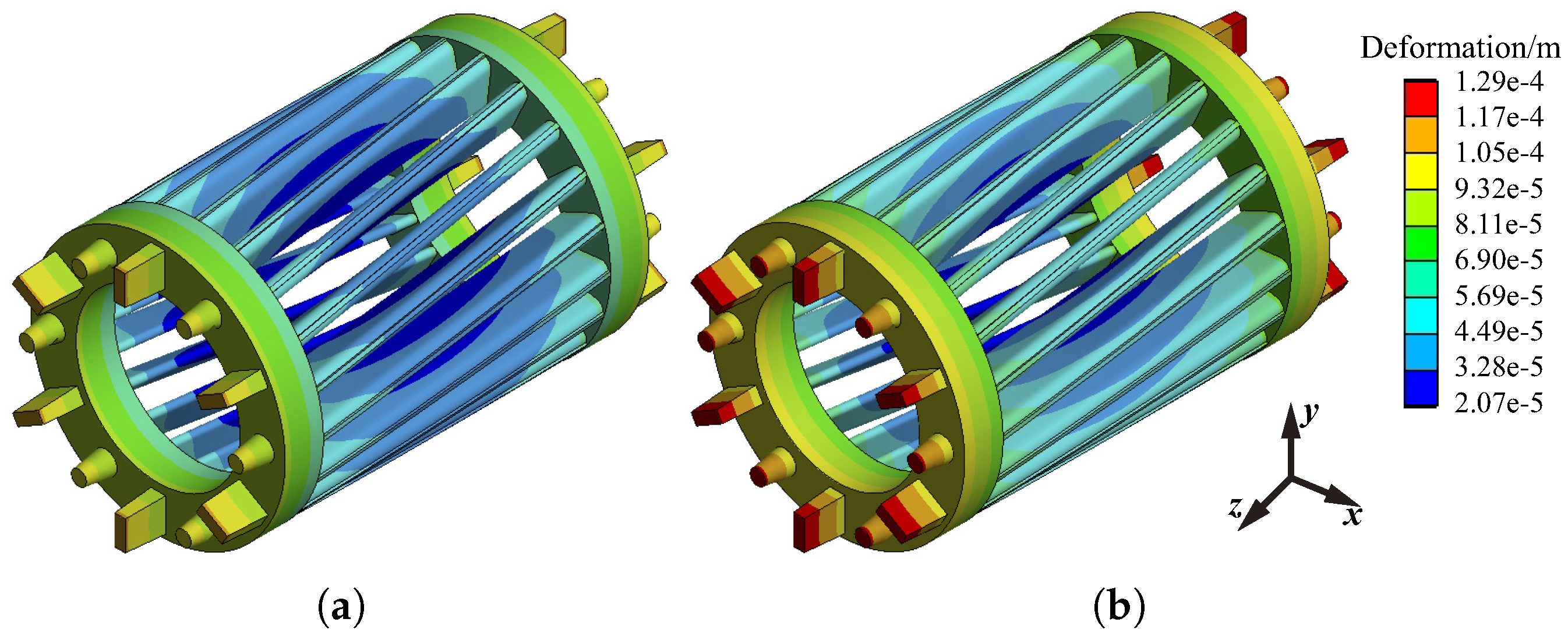
To be consistent with the above thermal field analysis, the analysis results of normal and faulty motor rotors in this section are the ones at 90 min and 45 min, respectively. Figure 13 shows the deformation of the squirrel cage before and after the fault. The distribution law of deformation is the same under two conditions. The maximum value of deformation appears at the position of the fan and balance weight in the end-ring, and the minimum value appears at the bottom of the axial middle position of the bar. Due to the great difference temperature under the two conditions, the maximum value of rotor deformation after fault is 19.7% higher than that of the normal motor.
The distribution law of rotor thermal stress is different from that of deformation. It can be seen from Figure 14 that under the two working conditions, the minimum value of Von Mises stress appears at the rotor end ring, the maximum value appears at the bottom of the bar near the joint region of the end ring, and the thermal stress values at the joint region are large. The maximum value of thermal stress increases by 20.3% after the fault, and the position of thermal stress distribution is significantly different.
The motor studied in [13] has the same power level as the motor in this paper; thus, one can compare the thermal stress results of the broken bar fault in [13] and the results in this paper. In [13], the thermal deformation and thermal stress of the faulty motor are increased by 7.4% and 8%, respectively, compared with tose of the normal motor when the rotor has one broken bar, and they are further increased by 23.8% and 24% when the rotor has two broken bars. On the other hand, the thermal deformation and thermal stress after ITF are 19.7% and 20.3% higher, respectively, than the normal motor in this paper. By comparison, it can be seen that the thermal stress value in this study is similar to the rotor fault of two broken bars, indicating that ITF has a high possibility of causing rotor fault.
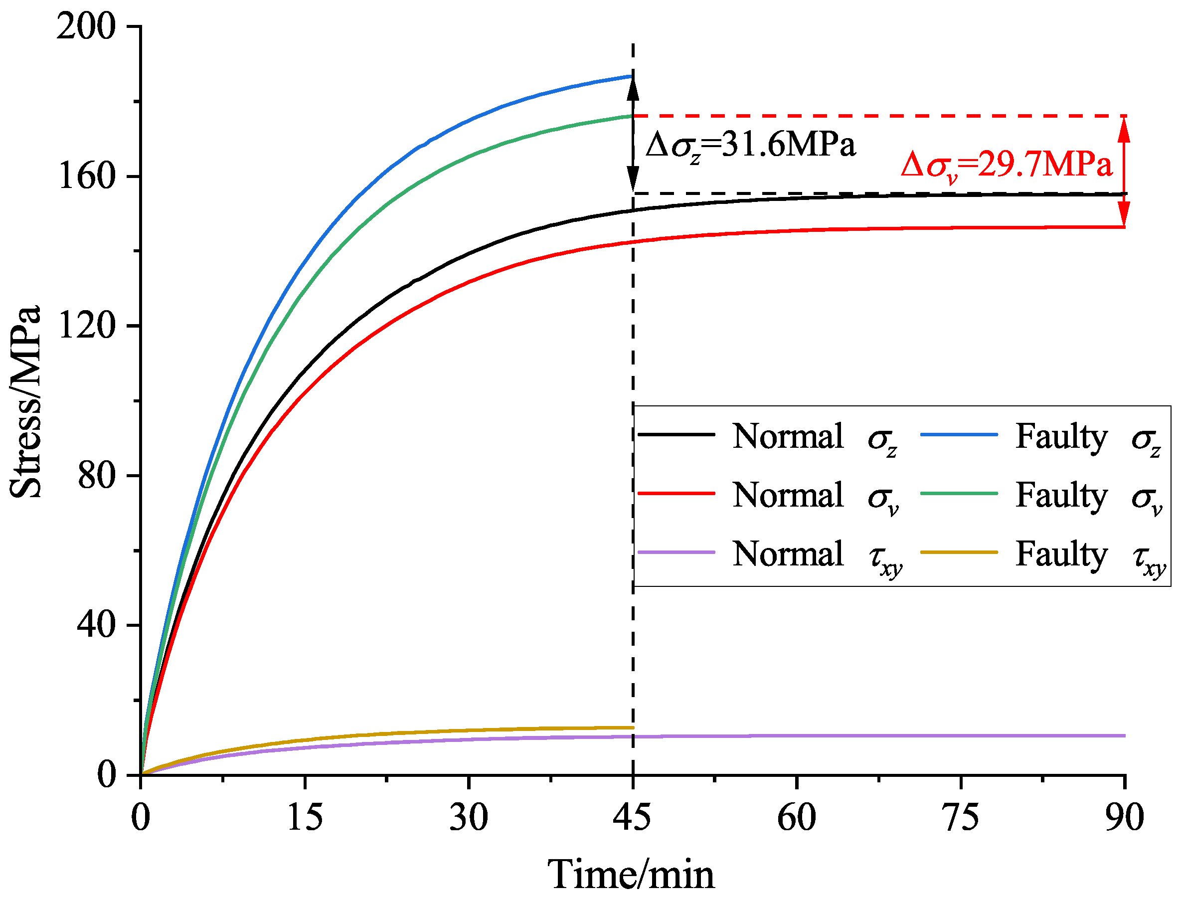
The curves of maximum normal stress, maximum shear stress, and Von Mises stress of the squirrel cage rotor with time are shown in Figure 15. The shear stress in the thermal stress of the squirrel cage is much less than the normal stress before and after the fault. The maximum direction of normal stress is axial (z-direction indicated in Figure 14). Since the Von Mises stress is an equivalent value, the maximum normal stress is slightly larger than the Von Mises stress. After the fault, both σ z and σ v are significantly improved, which further increases the possibility of rotor fault.
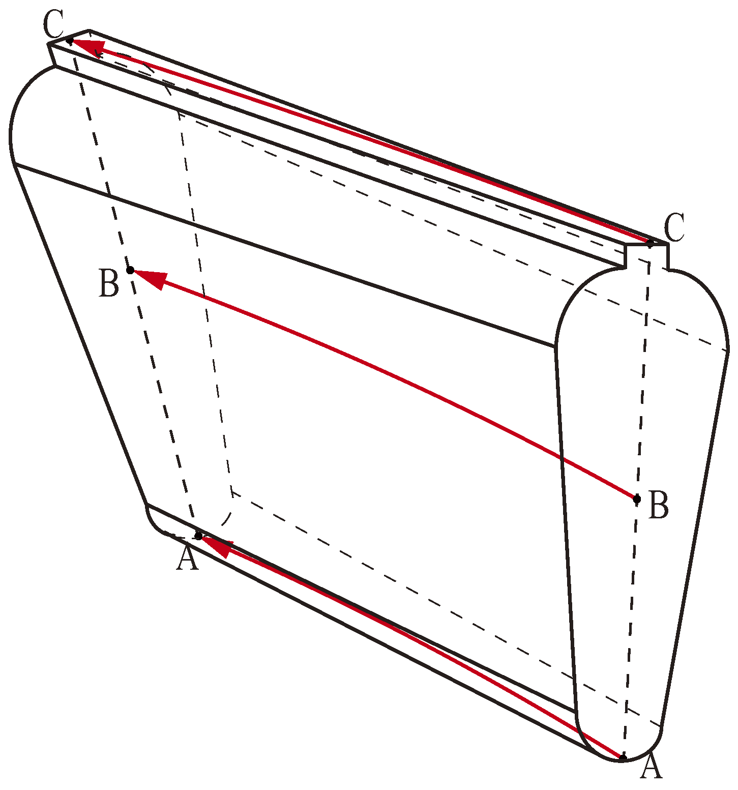
It has been shown that the broken bar fault is the most common fault of the rotor and that the fault is prone to occur at the connection joint between the bar and the end-ring [13]. The results in Figure 14 show that the stress distribution at different bar positions is quite different. In order to study this complex stress distribution, the distribution of thermal stress along different paths of the bars is analyzed. Take any bar in the squirrel cage, and the analysis paths are shown in Figure 16, which shows the bottom path A-A, the middle path B-B, and the top path C-C.
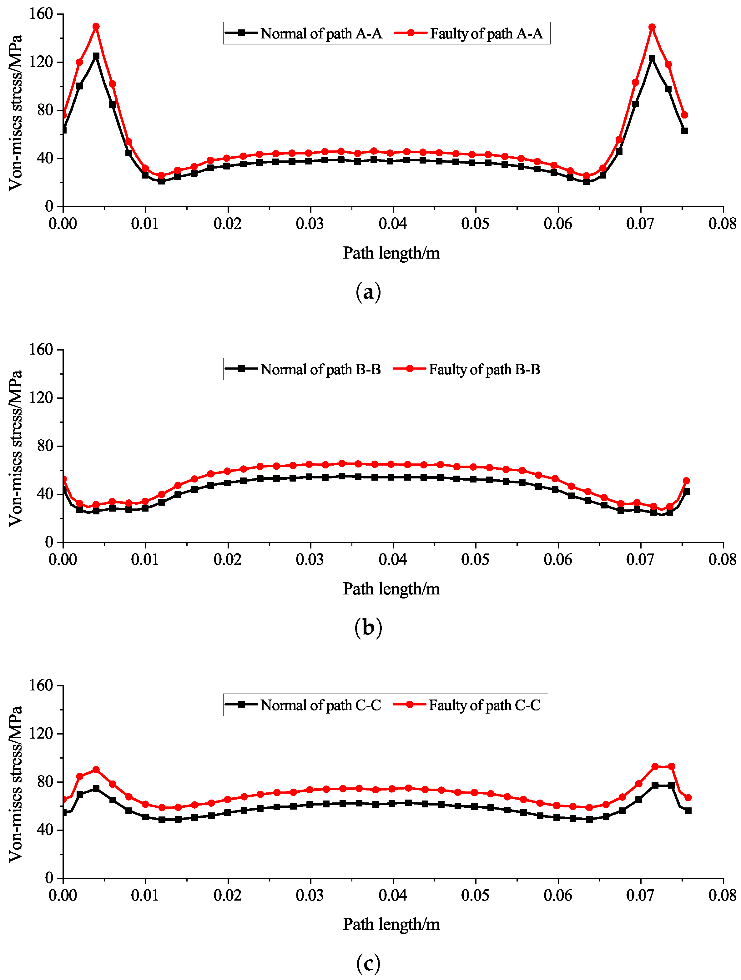
The thermal stress distribution along paths A-A and C-C shows that the stress value in the axial middle is low, and the maximum value appears near the end-ring connection. On the contrary, the stress distribution in the path B-B is high in the middle and low on both sides of the axial direction. After the fault, the stress values at each path increase to varying degrees. Taking the position of the maximum stress shown in Figure 17a as an example, we can see that the thermal stress value at this position after the fault increases by 20.7% compared with that under normal conditions. Since the connection joint between the bars and the end-ring is the prone position of the broken bar fault, there may be defects in the manufacturing process of the cast aluminum rotor, and the sharply increased thermal stress will increase the risk of the broken bar fault of the rotor.

7. Conclusions

In this paper, the thermal characteristics of an induction motor under a rated load before and after the stator ITF are analyzed using a 3D transient thermal field, stress-field simulation, and TR experiment, and the conclusions are as follows:
(1)
The original temperature distribution law of the motor is broken after ITF, and the hotspot of the motor is transferred from the rotor to the faulty slot winding. The TR of each part of the motor is higher than that under normal conditions, and the difference in space and time characteristics of temperature distribution is further increased due to the different TR values and TR rates of each part.
(2)
The significant thermal characteristic of ITF is the difference in winding temperature distribution. Taking the TR of normal winding in the first nine minutes as the standard, the TR value and TR time of winding in the faulty slot are 2.2 times and 11.1%, respectively, of those of the normal motor. The statistical variance data of winding temperature show that the fault causes the discrete distribution of winding temperature, and the variance value can provide a reference for fault diagnosis.
(3)
The rotor thermal stress analysis is introduced for the first time in studying the stator ITF in induction motors. The maximum thermal stress of the squirrel cage rotor occurs at the bottom of the bar near the joint of the end-ring. After the fault, due to the increase in rotor temperature, the thermal stress value at this place further increases (20.7% higher than that under normal conditions), which intensifies the risk of broken bar fault.
Moreover, further work is in progress to study the difference in TR characteristics under various fault degrees, assess the impact of fault on the remaining life of insulation, and propose a fault diagnosis method from the perspective of thermal characteristics.

Author Contributions

Conceptualization, P.C. and Y.X.; methodology, P.C.; investigation, P.C., Y.X. and D.L.; validation, P.C. and D.L.; data curation, P.C. and D.L.; writing—original draft preparation, P.C.; writing—review and editing, P.C., Y.X. and D.L.; visualization, P.C., Y.X. and D.L.; supervision, Y.X.; project administration, Y.X.; funding acquisition, Y.X. All authors have read and agreed to the published version of the manuscript.

Funding

This work was supported by the National Natural Science Foundation of China under Grant 51977052 and Grant U21A20145.

Institutional Review Board Statement

Not applicable.

Informed Consent Statement

Not applicable.

Data Availability Statement

Not applicable.

Conflicts of Interest

The authors declare no conflict of interest.

References

  1. Karmakar, S.; Chattopadhyay, S.; Mitra, M.; Sengupta, S. Induction Motor Fault Diagnosis: Approach through Current Signature Analysis; Springer: Berlin/Heidelberg, Germany, 2016. [Google Scholar]
  2. Zhang, P.; Du, Y.; Habetler, T.G.; Lu, B. A survey of condition monitoring and protection methods for medium-voltage induction motors. IEEE Trans. Ind. Appl. 2010, 47, 34–46. [Google Scholar] [CrossRef]
  3. Qiu, H.; Yu, W.; Tang, B.; Yang, C.; Zhao, H. Research on the influence of inter-turn short circuit fault on the temperature field of permanent magnet synchronous motor. J. Electr. Eng. Technol. 2017, 12, 1566–1574. [Google Scholar]
  4. Bento, F.; Adouni, A.; Muxiri, A.C.; Fonseca, D.S.; Marques Cardoso, A.J. On the risk of failure to prevent induction motors permanent damage, due to the short available time-to-diagnosis of inter-turn short-circuit faults. IET Electr. Power Appl. 2021, 15, 51–62. [Google Scholar] [CrossRef]
  5. Adouni, A.; Cardoso, A.J.M. Thermal analysis of low-power three-phase induction motors operating under voltage unbalance and inter-turn short circuit faults. Machines 2020, 9, 2. [Google Scholar] [CrossRef]
  6. He, Y.; Zhang, W.; Xu, M.; Tao, W.; Liu, H.; Dou, L.; Wan, S.; Li, J.; Gerada, D. Rotor loss and temperature variation under single and combined faults composed of static air-gap eccentricity and rotor inter-turn short circuit in synchronous generators. IET Electr. Power. Appl. 2021, 15, 1529–1546. [Google Scholar] [CrossRef]
  7. Shi, Y.; Wang, J.; Wang, B. Electromagnetic-thermal coupled simulation under various fault conditions of a triple redundant 9-phase PMASynRM. IEEE Trans. Ind. Appl. 2019, 56, 128–137. [Google Scholar] [CrossRef]
  8. Li, G.; Ojeda, J.; Hoang, E.; Gabsi, M. Thermal-electromagnetic analysis of a fault-tolerant dual-star flux-switching permanent magnet motor for critical applications. IET Electr. Power. Appl. 2011, 5, 503–513. [Google Scholar] [CrossRef] [Green Version]
  9. Shi, Y.; Wang, J.; Wang, B. Transient 3-D lumped parameter and 3-D FE thermal models of a PMASynRM under fault conditions with asymmetric temperature distribution. IEEE Trans. Ind. Electron. 2020, 68, 4623–4633. [Google Scholar] [CrossRef]
  10. Wan, Y.; Wu, S.; Cui, S. Choice of pole spacer materials for a high-speed PMSM based on the temperature rise and thermal stress. IEEE Trans. Appl. Supercond. 2016, 26, 0608405. [Google Scholar] [CrossRef]
  11. Chen, G.; Di, C.; Bao, X.; Xu, W. Calculation and Optimization of Thermal Stress in Induction Motor with Double-Skewed Rotor. In Proceedings of the 2021 24th International Conference on Electrical Machines and Systems (ICEMS), Gyeongju, Korea, 31 October–3 November 2021; pp. 1445–1449. [Google Scholar]
  12. Li, J.; Wang, L. Calculation and analysis of rotor thermal static field for inter-turn short circuit of large hydro-generator excitation winding. Energies 2019, 12, 1252. [Google Scholar] [CrossRef] [Green Version]
  13. Xie, Y.; Wang, Z.; Shan, X.; Li, Y. Investigation of rotor thermal stress in squirrel cage induction motor with broken bar faults. COMPEL-Int. J. Comput. Math. Electr. Electron. Eng. 2016, 35, 1865–1886. [Google Scholar] [CrossRef]
  14. Climente-Alarcon, V.; Arkkio, A.; Antonino-Daviu, J. Study of thermal stresses developed during a fatigue test on an electrical motor rotor cage. Int. J. Fatigue 2019, 120, 56–64. [Google Scholar] [CrossRef] [Green Version]
  15. Xie, Y. Performance evaluation and thermal fields analysis of induction motor with brok bars located at different relative positions. IEEE Trans. Magn. 2010, 46, 1243–1250. [Google Scholar]
  16. Boglietti, A.; Cossale, M.; Vaschetto, S.; Dutra, T. Thermal conductivity evaluation of fractional-slot concentrated-winding machines. IEEE Trans. Ind. Appl. 2017, 53, 2059–2065. [Google Scholar] [CrossRef]
  17. Xie, Y.; Wang, Y. 3D temperature field analysis of the induction motors with broken bar fault. Appl. Therm. Eng. 2014, 66, 25–34. [Google Scholar] [CrossRef]
  18. Huang, G.; Fu, F. Small and Medium-Sized Rotating Motor Design Handbook; China Electric Power Press: Beijing, China, 2007. [Google Scholar]
  19. Chen, P.; Xie, Y.; Hu, S. Electromagnetic Performance and Diagnosis of Induction Motors With Stator Interturn Fault. IEEE Trans. Ind. Appl. 2020, 57, 1354–1364. [Google Scholar] [CrossRef]
  20. Li, W.; Huang, B.; Bi, Z. Thermal Stress Theory Analysis and Application; China Electric Power Press: Beijing, China, 2004. [Google Scholar]
Figure 1. Equivalent model of a stator slot.
Machines 10 00504 g001
Figure 2. Simulation model of the motor thermal field.
Machines 10 00504 g002
Figure 3. Cross section of the prototype and internal TMP locations.
Machines 10 00504 g003
Figure 4. Motor TR experimental platform.
Machines 10 00504 g004
Figure 5. Equivalent circuit of the motor with ITF.
Machines 10 00504 g005
Figure 6. Core loss distribution of normal and faulty motors. (a) Normal. (b) Forty-five-turn fault.
Machines 10 00504 g006
Figure 7. TR curve of normal and faulty motor. (a) Normal. (b) Forty-five-turn fault.
Machines 10 00504 g007
Figure 8. Temperature distributions of normal and faulty motor. (a) Normal motor. (b) Normal stator core. (c) Normal rotor. (d) Faulty motor. (e) Faulty stator core. (f) Faulty rotor.
Machines 10 00504 g008
Figure 9. Winding temperature distributions of normal and faulty motor. (a) Normal. (b) Forty-five-turn fault.
Machines 10 00504 g009
Figure 10. Measured TR curve at TMP-A in the first nine minutes.
Machines 10 00504 g010
Figure 11. Variation of TR and TR time at each TMP.
Machines 10 00504 g011
Figure 12. Temperature distribution of motor windings at different moments. (a) Five minutes. (b) Thirty minutes. (c) Final moment.
Machines 10 00504 g012
Figure 13. Deformation of squirrel cage rotor before and after the fault. (a) Normal. (b) Forty-five-turn fault.
Machines 10 00504 g013
Figure 14. Von Mises stress distribution of squirrel cage rotor before and after the fault. (a) Normal. (b) Forty-five-turn fault.
Machines 10 00504 g014
Figure 15. Stress variation curve with time at the maximum stress point.
Machines 10 00504 g015
Figure 16. Thermal stress measurement paths of a bar.
Machines 10 00504 g016
Figure 17. Thermal stress distribution along the paths of normal and faulty barss. (a) Path A-A. (b) Path B-B. (c) Path C-C.
Machines 10 00504 g017
Table 1. Prototype parameters.
ParametersUnitsValue
Cooling type-TEFC
Insulation class-F
Pole pairs-1
Stator/rotor slot number-24/20
Number of turns in series per phase-256
Rated powerkW1.1
Rated speedrpm2850
Outer/inner diameter of statormm120/67
Air-gap lengthmm0.3
Inner diameter of rotormm26
Core lengthmm75
Table 2. Material properties of prototype.
Motor PartsMaterialThermal Conductivity
W/(m·K)
Density kg/m 3 Specific Heat Capacity
J/(kg·K)
Stator and rotor coreSilicon steel sheet39 (radial), 4 (axial)7700470
Stator coilCopper3868900385
Equivalent insulation in slotInsulation material0.1412001000
Equivalent air-gapAir0.031.1641013
Rotor cageCast aluminium2212689950
Housing and end capCast iron487350460
Shaft45# steel50.27850434
BearingBearing steel357810450
WedgeWood0.519001150
Table 3. Heat dissipation boundary conditions of the simulation model.
Heat Dissipation SurfaceCalculation FormulaVariable DescriptionValue/W/(m 2 · K)
S 1 —Housing outer surface α f = 9.73 + 14 v 0.62 v is the wind velocity on the housing surface.29.2–65.9
S 2 —End cap outer surface α e c 1 = 20 + 14.3 μ 0 0.6 α e c 2 = 20 + 2.6 μ 0 0.6 α e c 1 represents the fan side and α e c 2 represents the load side; μ 0 is half of the circumferential velocity at the outer diameter of the fan.28.9, 69
S 3 —Contact surface between stator core and housing R δ = δ 0 λ α A 0 = 1 α 0 A 0 α 0 = λ α δ 0 R δ is the equivalent conduction thermal resistance, and it is assumed that the equivalent heat transfer resistance is equal to it; δ 0 and A 0 are the air-gap length and the heat conduction area between stator core and housing.500
S 4 —End face of stator core   α s e = 15 + 6.5 v r l 0.7 v r l = π D 2 n 60 v r l is the linear speed of the rotor surface; D 2 is the outer diameter of the rotor; n is the rotor speed.48.5
S 5 —End face of rotor core   α r e = 2 N u r λ α D 2 N u r = 1.67 R e r 0.385 R e r = π D 2 2 n 120 γ N u r is the Nusselt number; λ α is the thermal conductivity of air; R e r is the Reynolds number of the air at the rotor end face; γ is the kinematic viscosity of air.73.8
S 6 —Rotor end-ring surface   α e = N u r f λ α h r f N u r f = 0.456 R e r f 0.6 R e r f = π D 2 n h r f 60 γ N u r f is the Nusselt number; R e r f is the Reynolds number of the air at the rotor end-ring surface; h r f is rotor blade height.128.7
S 7 —Shaft surface α s = 7.8 v e q 0.78 v e q is 75% of circumferential velocity of shaft.18.4
Table 4. Comparison of motor copper loss under normal and faulty conditions.
ABCSCTotal
Normal/W54.1954.1954.190162.57
Fault/W78.8972.9459.8823.57235.28
Amplification45.6%34.6%10.5%-44.7%
(Normal phase resistance value is 8.6 Ω at 75 °C).
Table 5. Comparison of TRs of TMPs before and after fault. (units: °C for temperature, K for TR).
Normal
Condition
Measured
Temperature
Simulated
Temperature
Measured TRSimulated TR
TMP-A87.285.266.164.4
TMP-B85.384.665.463.8
TMP-C91.788.270.567.4
TMP-D83.284.46363.6
TMP-E75.472.555.151.7
TMP-F69.767.448.546.6
TMP-G75.676.956.156.1
TMP-H72.472.552.551.7
Faulty
Condition
Measured
Temperature
Simulated
Temperature
Measured
TR
Simulated
TR
TMP-A134.4131.95112.8110.95
TMP-B107.9110.187.589.1
TMP-C103.5102.181.881.1
TMP-D93.897.373.176.3
TMP-E86.586.165.765.1
TMP-F78.977.857.256.8
TMP-G87.190.567.169.5
TMP-H83.282.962.861.9
The room temperature is 20.8 °C and 21 °C in the rated load test under normal and fault conditions. These two temperatures are taken as the initial temperature in the corresponding simulation, and the initial temperature of each TMP in the experiment is subject to the actual measurement.
Table 6. Winding temperature variance statistics at each moment.
S 2 5 min30 minFinal
NormalFaultyNormalFaultyNormalFaulty
S 1 2 0.03102.051.02101.661.61101.93
S 2 2 0.0839.281.5242.622.3043.65
S 3 2 0.06263.521.47260.442.26260.45
Publisher’s Note: MDPI stays neutral with regard to jurisdictional claims in published maps and institutional affiliations.