Abstract
Multi-lip reciprocating seals are extensively used in the subject of engineering equipment. However, the current research on the tribology of reciprocating seals mainly focused focuses on the numerical analysis of single-lip seals. In order to study the sealing performance of multi-lip seals, this paper takes double-acting seal (DAS) as the research object, and establishes a multi-lip mixed elastohydrodynamic lubrication (M-EHL) numerical simulation model from the perspective of solid mechanics, fluid mechanics, contact mechanics, and deformation mechanics. The sealing characteristics under different working conditions (sealed pressure, piston rod extension speed, and seal surface roughness) were analyzed by numerical calculation, and the variation trend of friction force corresponding to the experimental results was obtained. The model can provide a modeling guidance basis for the M-EHL characteristic analysis and structural optimization design of multi-lip reciprocating seals in the mechanical field.
1. Introduction
Although reciprocating seals are an auxiliary component of hydraulic actuators, their excellent sealing performance is one of the key factors that directly affects the safety of hydraulic systems [1]. In the past few decades, there has been little research on reciprocating seals, and even this research has not conducted in-depth research on its seal mechanism. If the working mechanism of the seal is not sufficiently understood, seal failure may occur due to improper use, and the final loss is unpredictable. Therefore, it is important to study the reciprocating seal mechanism for correct use and improvement of sealing performance.
Between 1944 and 1947, White and Denny first studied the working mechanism and sealing performance of reciprocating seals from the perspective of theoretical analysis. Since then, people have carried out much theoretical and experimental research on reciprocating seals [2]. The experimental results show that when the piston rod is reciprocating motion, the fluid film formed in the sealing interface has a lubrication effect on the relative motion due to the hydrodynamic effect [3]. There are two different methods of solving fluid film mechanics, which can be divided into elastohydrodynamic lubrication (EHL) theory and inverse hydrodynamic lubrication (IHL) theory. Since the IHL method is based on the assumption of full film lubrication, the influence of fluid dynamic pressure on the seal deformation is ignored, which greatly limits the application of the IHL theory. The EHL method dynamically balances the static contact pressure and the fluid pressure, which can more accurately reflect the effect of the lubrication film on the sealing performance. With the continuous improvement of modern computer capability, researchers began to use elastohydrodynamic lubrication (EHL) theory considering asperity surface contact to analyze sealing characteristics on the premise of satisfying the calculation accuracy. The analysis results show that the sealing zone is always in a mixed lubrication state, which is consistent with the previous experimental data [4]. Relevant research work mainly focuses on single seals such as O-ring seal [5,6,7], U-cup seal [8,9,10,11,12], and rectangular ring [13,14,15], and a series of simulation studies were conducted on C-shape combined seal, T-shape combined seal [16], VL combined seal [17,18], and step combined seal [19,20]. Table 1 lists the solutions for the above related seal lubrication characteristics. However, these seals have a single structure, and the seal has only one seal lip in contact with the cylinder, which makes it easier to obtain calculation results during the analysis process.

Table 1.
Comparison of some typical single seals with combined seals.
In practical work, due to the machining and assembly accuracy error, heavy load conditions, bad working environment, and poor lubrication of the hydraulic cylinder can lead to the slight twisting of the hydraulic cylinder piston rod, bending deformations, and other eccentric load phenomena. In this case, the single seal has difficulty meeting the seal requirements of the reciprocating motion system and in keeping the piston rod reciprocating horizontally, and in most of the single seals only one elastic seal body plays a sealing role. In order to improve the operation stability of the sealing equipment, more and more combined seals are widely used. These combined seals often have multiple seal lips in contact with the sealing zone, which plays a multi-lip sealing effect on the seal system. However, the literature survey shows that there are few studies on the multi-lip combined seal with complex structure. Only Yang et al. [21] studied the mixed elastohydrodynamic lubrication (M-EHL) characteristics of a double-lip U-cup hydraulic rod seal by numerical simulation. Research has found that the sealing performance of double-lip seals and single-lips seal is very different during the reciprocating motion. The fluid pressure between the double lips makes the two seal lips form a strong coupling relationship.
In order to study the sealing mechanism of multi-lip seals, this paper takes the multi-lip double-acting seal (DAS) commonly used in construction machinery as the research object. First, the finite element modeling of the DAS combined seal is carried out by ANSYS software, and the finite element results of static pressure distribution and deformation analysis of the seal are obtained. Then, on the basis of EHL, the numerical model of the multi-lip strong fluid–solid coupling mixed lubrication of DAS combined seal is established by using MATLAB software. The effects of sealing pressure, piston speed, and sealing surface roughness on the lubrication characteristics were numerically calculated, and the tribological properties of each seal lip under the action of fluid–structure interaction were revealed. Finally, the numerical calculation and the experimental test are compared and discussed. The research results can provide theoretical guidance for the lubrication performance and structural optimization of multi-lip reciprocating seals.
2. Theoretical Models
2.1. Geometrical Model
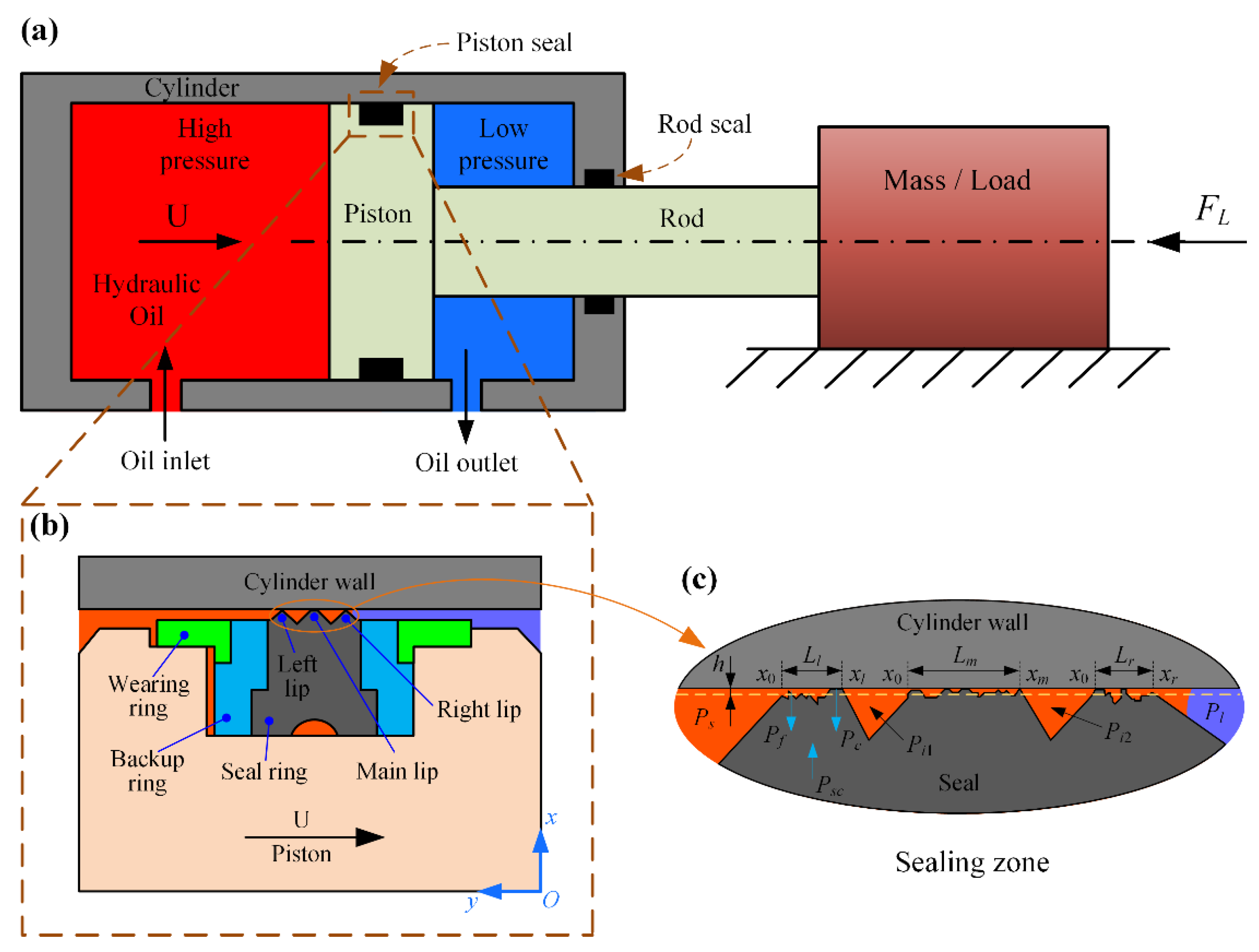
Figure 1 shows the typical working principle of the multi-lip DAS combined seal on the hydraulic cylinder piston. Figure 1a shows the working condition of the hydraulic cylinder. During the hydraulic cylinder piston rod drive load extension, the high-pressure oil enters the hydraulic cylinder rodless chamber, and the low-pressure oil in the hydraulic cylinder rod chamber is discharged into the tank. The DAS combined seal consists of a nitrile rubber (NBR) tooth-shaped seal ring, two thermoplastic polyester elastomer (TPE) backup rings, and two polyformaldehyde (POM) L-shaped wearing rings, as shown in Figure 1b. Among them, the elastic tooth-shaped seal ring plays a major role in the seal, and its outer side has three seal lips: the wider middle seal lip is the main seal lip, and the two outer seal lips as two secondary seal lips, which are distributed on the left and right sides of the main seal lip. The sealing details between the seal lip and the contact region of the cylinder wall are shown in Figure 1c. During the piston rod extension, the piston seal on the rodless chamber side is subjected to high fluid pressure, and the seal contact zone is squeezed and deformed. The piston seal on the rod chamber side is subjected to low fluid pressure, which is considered to be ambient pressure. Due to the large roughness of the seal rubber surface, the asperity contact always occurs at some bulge points on the seal surface, so the sealing zone is considered to be in a mixed lubrication state.
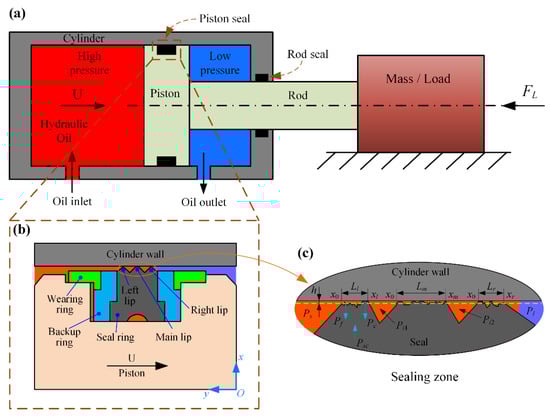
Figure 1.
Working schematic of the DAS combined seal: (a) Working condition of hydraulic cylinder; (b) DAS combined seal structural composition; (c) details information of the sealing zone.
2.2. Solid Mechanics
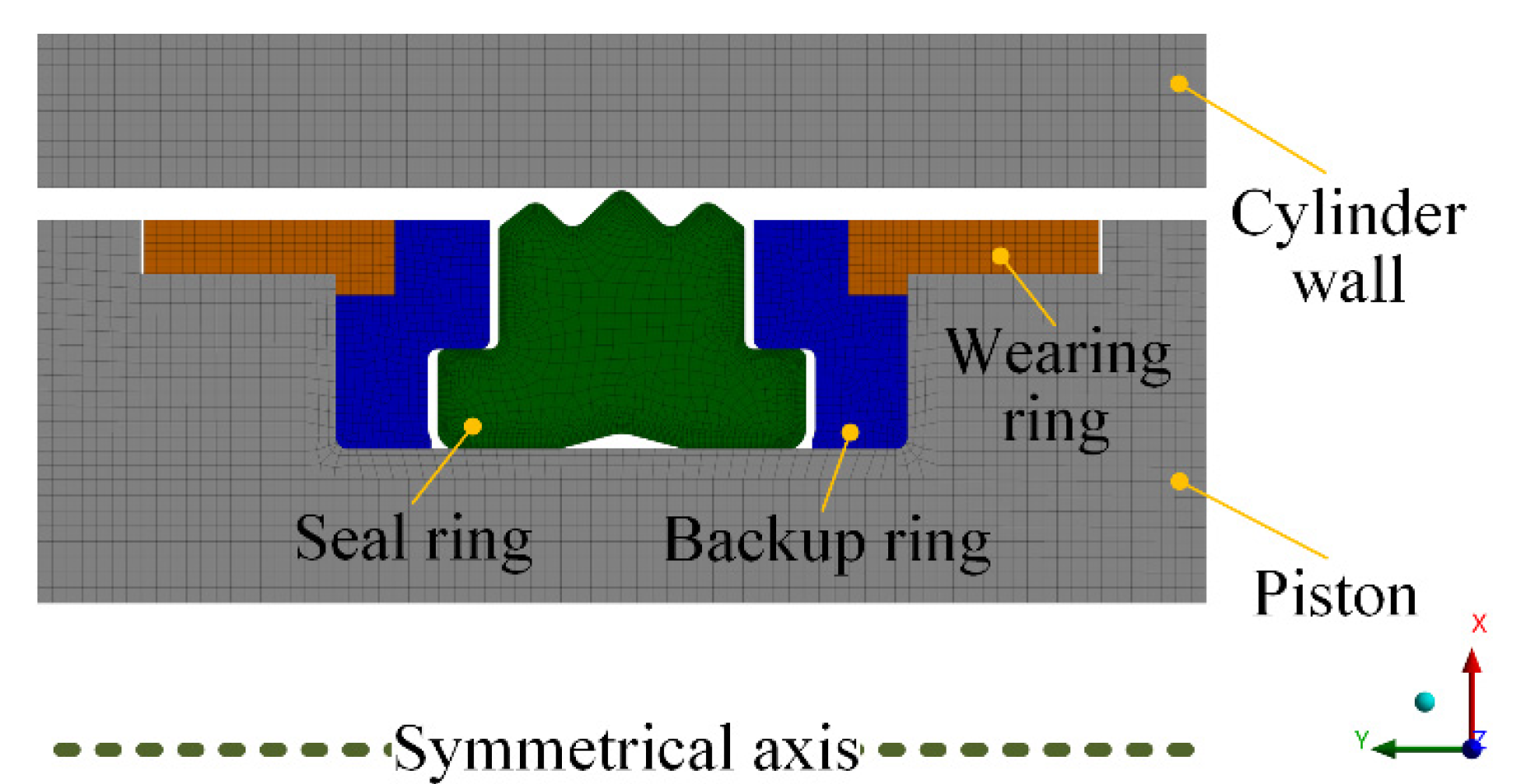
Since DAS combined seal has axisymmetric properties in structure, external loads, and constraint conditions, and in order to enhance computation performance, the 3-D model is simplified to a 2-D model by using the commercial software ANSYS for axisymmetric finite element analysis. In Figure 2, the model consists of a piston, cylinder wall, seal ring, backup ring, and wearing ring. The cylinder wall and piston are positioned by applying displacement constraints in X and Y directions, and the seal elements are positioned with contact constraints. Since the tooth-shaped seal ring belongs to the strong elastic material, the PLANE183 element with large strain and deformation capacity is selected for the mesh type. In order to obtain higher precision analysis results, the tooth-shaped ring external region is refined, and the calculation model has a total of 33,900 nodes. Compared with the further refined model (68,800 nodes in total) for mesh independent verification, the calculation error of contact pressure and stress is less than 0.5%, and the model is considered to converge under this mesh accuracy.

Figure 2.
The axisymmetric model established in the FEA software.
Since pistons and rods are commonly made of steel, the linear isotropic model is employed to characterize their material properties. NBR seal ring is an incompressible hyperelastic material, and its calculation model will show complex material nonlinearity and geometric nonlinearity under stress. Currently, the neo-Hookean model, Ogden–Tschoegl model, and Mooney–Rivlin model [22,23,24,25] have been used to describe the nonlinear elastic material characteristics of NBR. The Mooney–Rivlin model can well reflect the consistency between the hyperelastic model and material mechanical properties, and is the preferred model for finite element analysis in engineering problems [26]; its function model can be expressed as:
where WM−R is the strain energy density; C10, C01 are the Mooney–Rivlin coefficients of the material, which describe the shear characteristics of the material; I1, I2 are the strain tensor invariants, and J is the elastic volume ratio. According to the rubber compression test, the values of C10, C01, and d are 1.87 MPa, 0.47 MPa, and 0.0008547 [26], respectively.
2.3. Fluid Mechanics
Due to the effect of fluid dynamics, the sealing condition of the system can be evaluated by calculating the distribution law of film pressure and thickness. Assuming that the fluid medium is an incompressible Newtonian fluid, the correspondence between the film pressure and thickness can be described by the Reynolds equation. Since the sealing system is an axisymmetric structure, and the film thickness (micrometer level) is extremely small compared with the seal geometric size (millimeter level), it is considered that the fluid film is one-dimensionally distributed in the Cartesian coordinate system. The cylinder wall surface roughness is very small, and cavitation may occur in the sealing zone during reciprocating motion; Jakobsson–Floberg–Olsson (JFO) cavitation boundary conditions are used to predict the cavitation phenomenon of sealing zone [27]. Thus, the Reynolds equation considering both cavitation effect and surface roughness is adopted [28] (the derivation process of the equation is given in Appendix A):
where is the dimensionless axial coordinate, H is the dimensionless film thickness, HT is the dimensionless average truncated film thickness, U is the dimensionless piston speed, is the dimensionless pressure–viscosity coefficient, F is the cavitation index, Φ is the fluid pressure or the density of the cavitation region, ϕxx and ϕs.c.x are the pressure flow factor and shear flow factor under roughness effect, which are used to correct the direct effects of the contact surface roughness on the flow field such as film pressure, thickness, and velocity. They can be obtained in Patir and Cheng [29,30].
The cavitation factor F is similar to a weighting function and can also be called the density factor. When the film pressure Φ is greater than 0 (no cavitation), F = 1. Conversely, in cavitation, F = 0. The general variable Φ can be explained by:
According to the law of conservation of mass, the mass flow rates past the three sealing zones of the DAS combined seal must be the same under steady-state conditions. The inner boundary pressure of the left lip is equal to the sealed pressure (high-pressure fluid side), while the fluid pressure at the outer boundary is the same as the pressure in the first inter-lip region. Similarly, the fluid pressure at the inner boundary of the main lip and the right lip is equal to the pressure in the first and second inter-lip region, while the fluid pressure at the outer boundary is the pressure in the second inter-lip region and the low-pressure side, respectively.
As shown in Figure 1c, the axial region of the tooth-shaped seal ring and the cylinder wall can be divided into contact region and non-contact region (inter-lip region). The film thickness in the inter-lip region of is also on the millimeter level, which does not satisfy the 1-D properties of Equation (2). Therefore, the fluid film distribution of the three lips should be analyzed separately. In summary, the boundary conditions for the DAS seal to satisfy the Reynolds equation are:
In the Reynolds equation, the calculation formula of the dimensionless average truncated film thickness HT is:
where f(δ) is the probability density function of the seal surface roughness.
Assuming that the seal lip roughness obeys Gaussian distribution, Equation (5) can be rewritten as:
2.4. Contact Mechanics
In the analysis of M-EHL, the asperity contact pressure between the seal surface and the cylinder wall cannot be ignored. According to the Greenwood–Williamson (G–W) surface contact model [31], the asperity pressure is expressed as (the derivation process of the equation is given in Appendix A):
where η is the seal asperity density, R is the asperity radius, and σ is the RMS roughness of the seal surface.
2.5. Deformation Mechanics
Since the normal deformation (film thickness) of the sealing zone is micron level, the influence of the micro deformation in the sealing zone on the macro deformation of the seal ring can be ignored. According to the small deformation theory, it is considered that the normal deformation of any location in the sealing zone is a positive linear relationship with the applied load, so the micro deformation can be obtained by the influence coefficient method [32].
Based on the above assumptions, the film thickness of the i-th node in the sealing zone can be calculated by the following formula:
where Hs is the initial film thickness, K is the deformation coefficient matrix. The first and last contact mesh nodes in three sealing zones are used as matrix boundary nodes, the deformation coefficient matrix is obtained by sequentially applying unit load to each node of each sealing zone. (K)ik is the normal deformation caused by the i-th node when the unit load is applied to the k-th node, Psc is the static contact pressure obtained in ANSYS software.
The initial film thickness Hs is calculated by substituting Psc into the Pc of Equation (7), and then the linear regression fitting method is used to solve [33]; the empirical formula is as follows:
where,
2.6. Check Convergence and Auxiliary Calculation
2.6.1. Check Convergence
In steady-state conditions, the fluid film pressure Pf, asperity contact pressure Pc and static contact pressure Psc satisfy the force balance equation, Pf + Pc = Psc, and the mass flow rate past the three seal lips must also be equal. Therefore, the convergence criterion can be expressed as:
where,
where ε is the convergence tolerance, , and are the mass flow rate the left lip, main lip, and right lip, respectively.
2.6.2. Auxiliary Calculation
After strong coupling iterative convergence, the leakage and friction of the seal can be further obtained.
The calculation formula of flow rate is:
The calculation formula of actual leakage is:
The calculation formula of viscous shear stress in the sealing zone is:
where , , is the shear stress factor, which is obtained from literature [30].
The calculation formula of asperity shear stress on the sealing zone is:
In the M-EHL condition, the total friction force in the sealing zone is composed of viscous friction and asperity friction, so:
Therefore, the total friction of the DAS combined seal is:
where , , are the friction forces of left lip, main lip, and right lip, respectively.
2.7. Computational Scheme
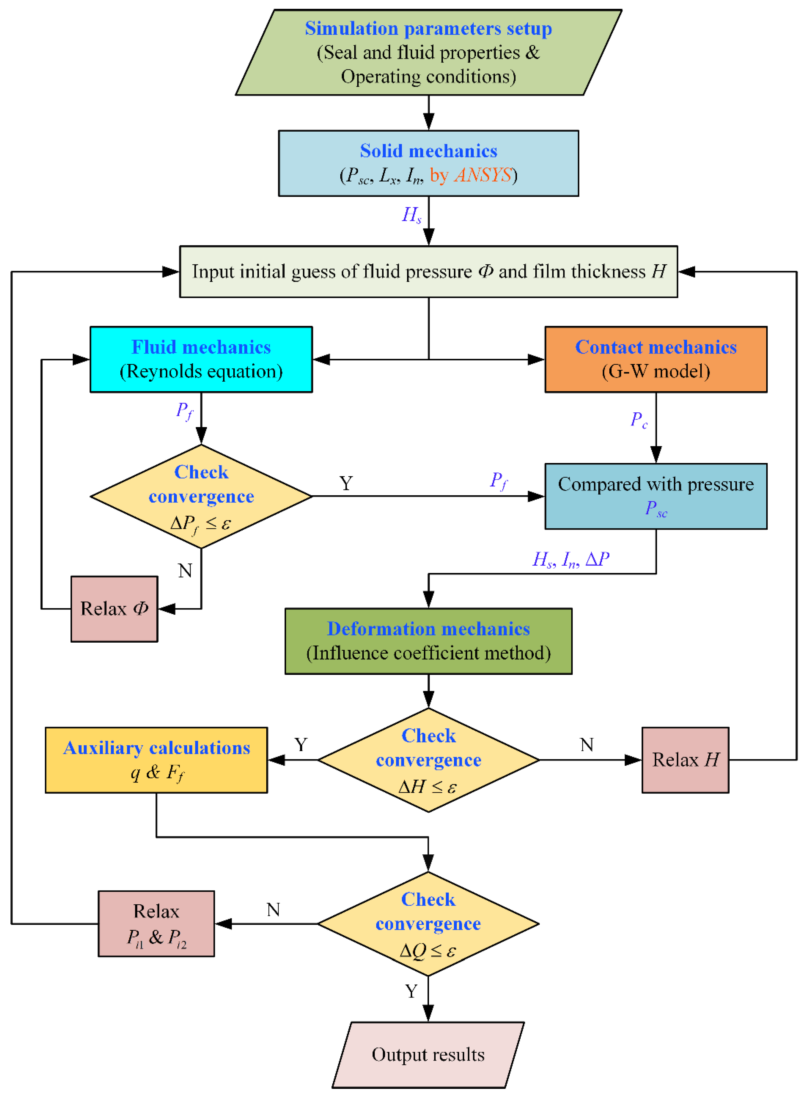
From the above analysis, it can be concluded that the relevant mechanics involved in the reciprocating sealing system have strong fluid–structure coupling nonlinear characteristics. Therefore, the iterative algorithm is selected for M-EHL analysis of DAS combined seal, and the calculation process is depicted in Figure 3. The specific operation steps are:

Figure 3.
Computational procedure of fluid–structure coupling numerical model.
- Input the fluid property parameters (including fluid viscosity μ, pressure–viscosity coefficient α, etc.), the operating conditions parameters (including fluid sealed pressure Ps, piston rod speed U) and the seal surface parameters (including RMS roughness σ, asperity density η, etc.) in the MATLAB software.
- Based on the basic structural parameters of the DAS sealing system, the large-scale finite element general analysis software ANSYS is used for solid mechanics calculation. The static contact pressure Psc, contact length Lx, and deformation coefficient matrix K in the sealing zone are obtained, respectively.
- The initial static film thickness Hs obtained by Psc was used to solve the Reynolds equation in fluid mechanics, until Pf converges, otherwise Φ is updated.
- The G–W contact model in contact mechanics was solved by Hs, and the asperity contact pressure Pc was obtained.
- Compare the sum of the fluid film pressure Pf and the asperity contact pressure Pc with the static contact pressure Psc to determine whether the three forces are balanced. If they are not balanced, the film thickness H is updated using the deformation coefficient matrix in the deformation mechanics and iterated repeatedly until the three forces are balanced.
- Auxiliary calculation of the flow through the three seal lips, whether , , and are equal. If not equal, return to step 3 to update the fluid pressures Pi1 and Pi2 between the inter-lip. Iterate the loop again until .
- The program calculation is completed and the results are output.
3. Simulation Parameters Setup
The basic structural and material property parameters for each component of the DAS combined sealing system are listed in Table 2.
Table 2.
Basic parameters of the DAS sealing system.
Hydraulic cylinder sealing performance is usually affected by fluid sealed pressure, piston rod speed, seal surface roughness, and other factors during reciprocating motion. Table 3 lists the specific operating parameters of the DAS combined seal M-EHL characteristic analysis under different working conditions.
Table 3.
Basic operating conditions parameters.
4. Results and Discussion
4.1. Macro Seal Characteristics
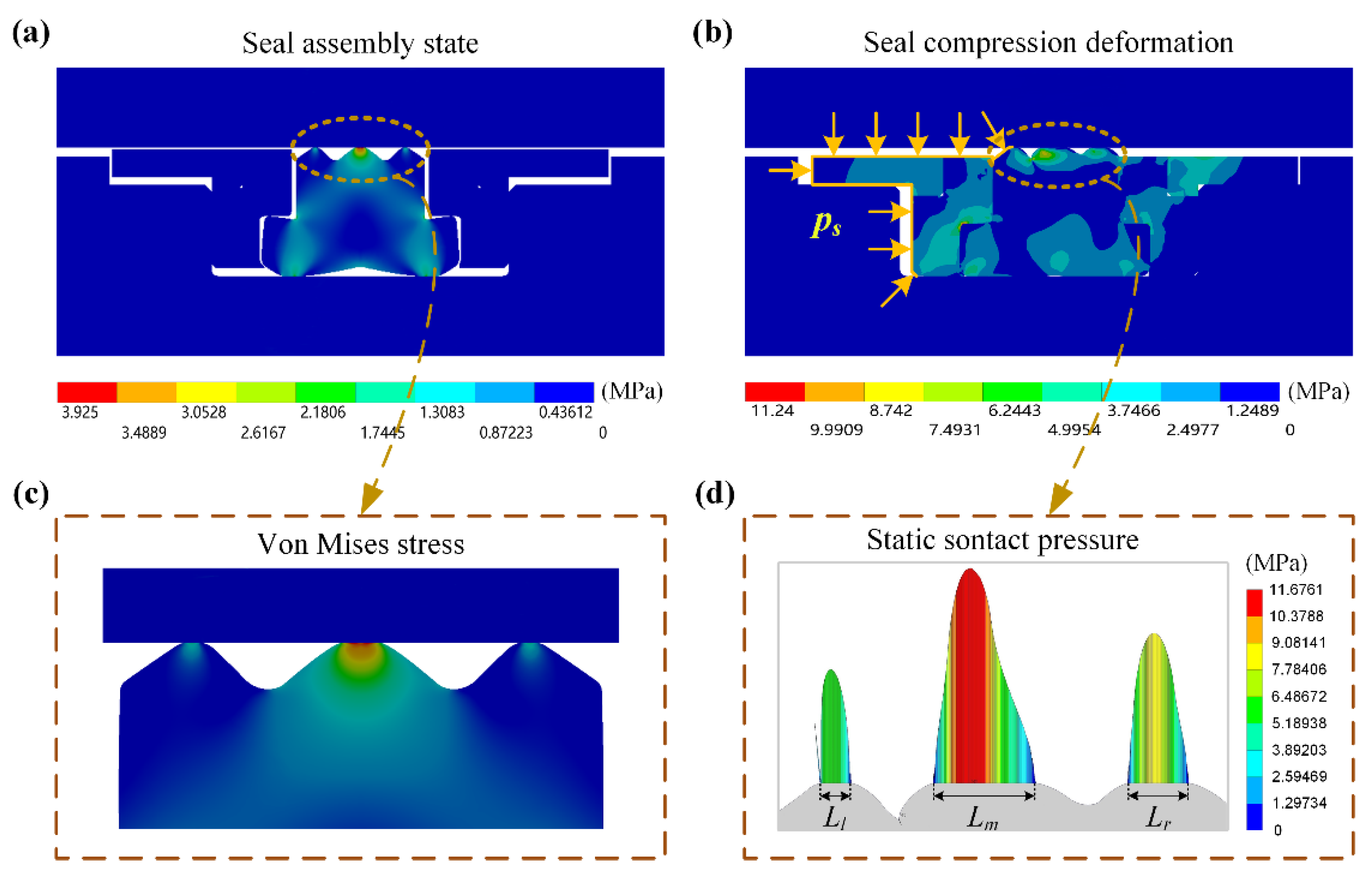
Figure 4 shows the finite element simulation results of interference installation and applied oil pressure for DAS combined seal. In order to simulate the interference assembly state, the tooth-shaped seal ring is pre-compressed and deformed by moving the cylinder wall downward in the vertical direction. The tooth-shaped seal ring von Mises stress is symmetrical distribution, as shown in Figure 4a. In order to simulate the effect of high-pressure fluid, sealed pressure is applied to the combined seal ring’s left side in the horizontal direction. Since the hardness of the backup ring and wearing ring is much larger than the seal ring, the seal ring is squeezed by the sealed pressure to produce a large deformation. The contact surface with the cylinder wall and the piston groove is tighter to prevent fluid leakage, as shown in Figure 4b. The enlarged view of the seal lip stress is presented in Figure 4c. It is obvious that the maximum von Mises stress is displayed at the contact interface between the main lip and cylinder wall, while the stress of the two secondary seal lips are relatively small. Therefore, the main seal lip first suffers local wear damage during its service life. Moreover, the seal is squeezed and the contact pressure distributed on the cylinder inner wall is asymmetrical. Among them, the contact pressure and the sealing length of the main seal lip are the largest, while the left seal lip on the high-pressure fluid side is the smallest. Figure 4d presents the contact length of the three seal lips are Ll, Lm, and Lr, respectively.

Figure 4.
Finite element analysis of sealing system installation and pressurization: (a) simulation of installation; (b) simulation of pressurization; (c) enlarged view of seal lip stress; (d) static contact pressure distribution.
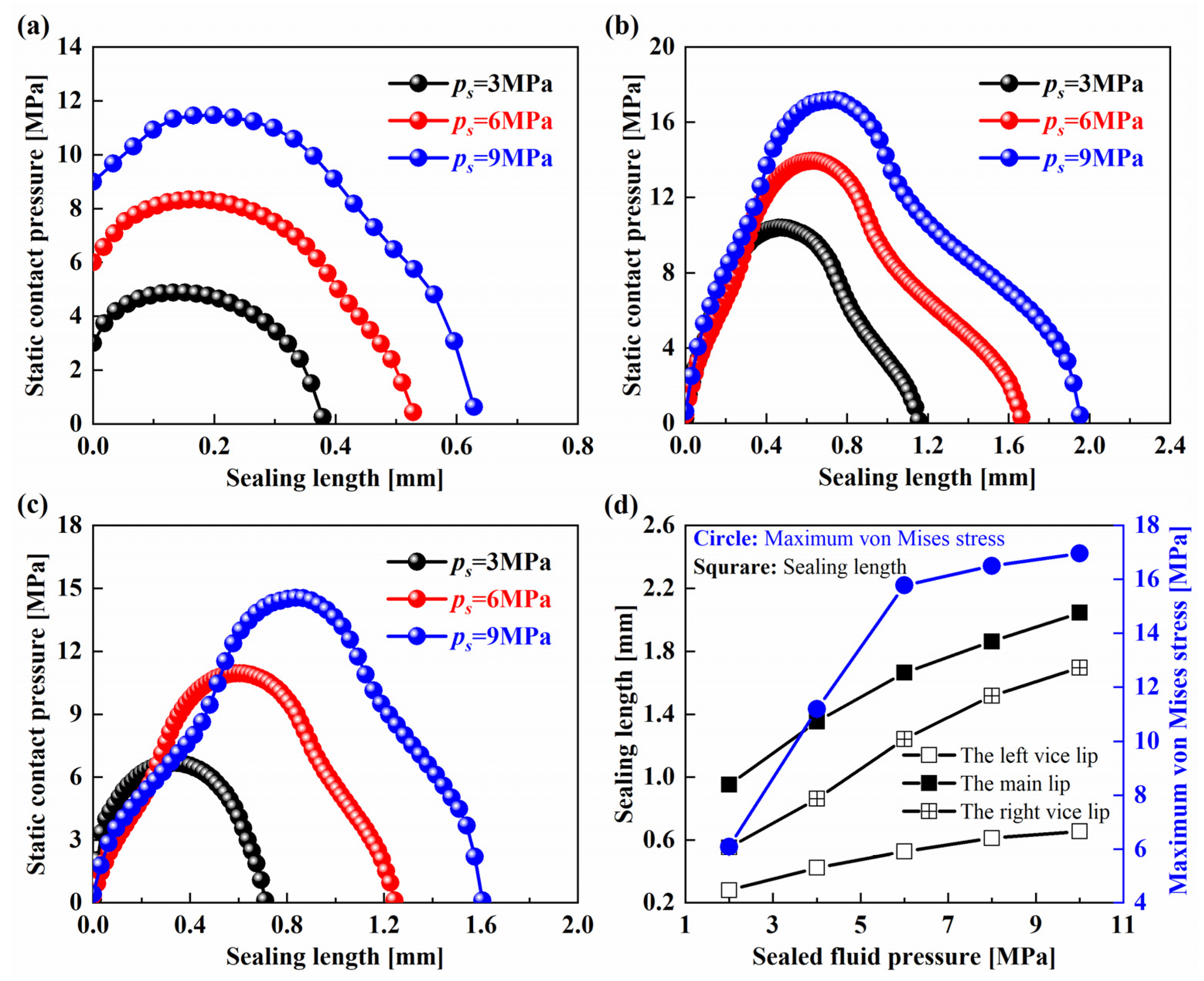
Figure 5 shows the static contact pressure and maximum von Mises stress distributions at different sealed pressures when the seal pre-compression amount is constant. From Figure 5a–c, the static contact pressure and contact length of the left lip, main lip, and right lip all increase with the increase of the fluid sealed pressure. For the left lip, the contact pressure gradient on the high-pressure fluid side is relatively large, while that of the low-pressure side is relatively small. The maximum static contact pressure of the main lip also tends to the high-pressure fluid side, while the contact pressure of the right lip shows a distribution law that transitions from a quadratic function to a Gaussian function. The sealing length of the three seal lips, and the corresponding maximum von Mises stress of the tooth-shaped seal ring increase gradually with the sealed pressure increase, see Figure 5d.
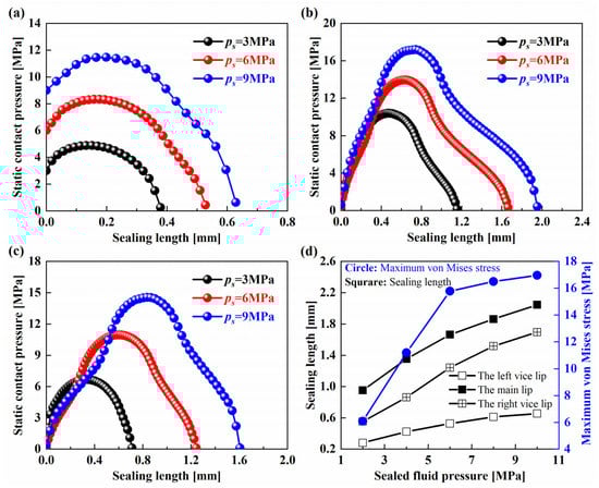
Figure 5.
Contact pressure and stress distributions: (a–c) the static contact pressure distributions of the left lip, main lip, and right lip; (d) sealing length and maximum von Mises stress distributions.
4.2. Micro Seal Characteristics
Based on the above, the sealing performance of the DAS combined seal under different fluid sealed pressure, piston rod speed, and seal surface roughness is analyzed and discussed by using multi-lip M-EHL numerical model.
4.2.1. Lubrication Characteristics
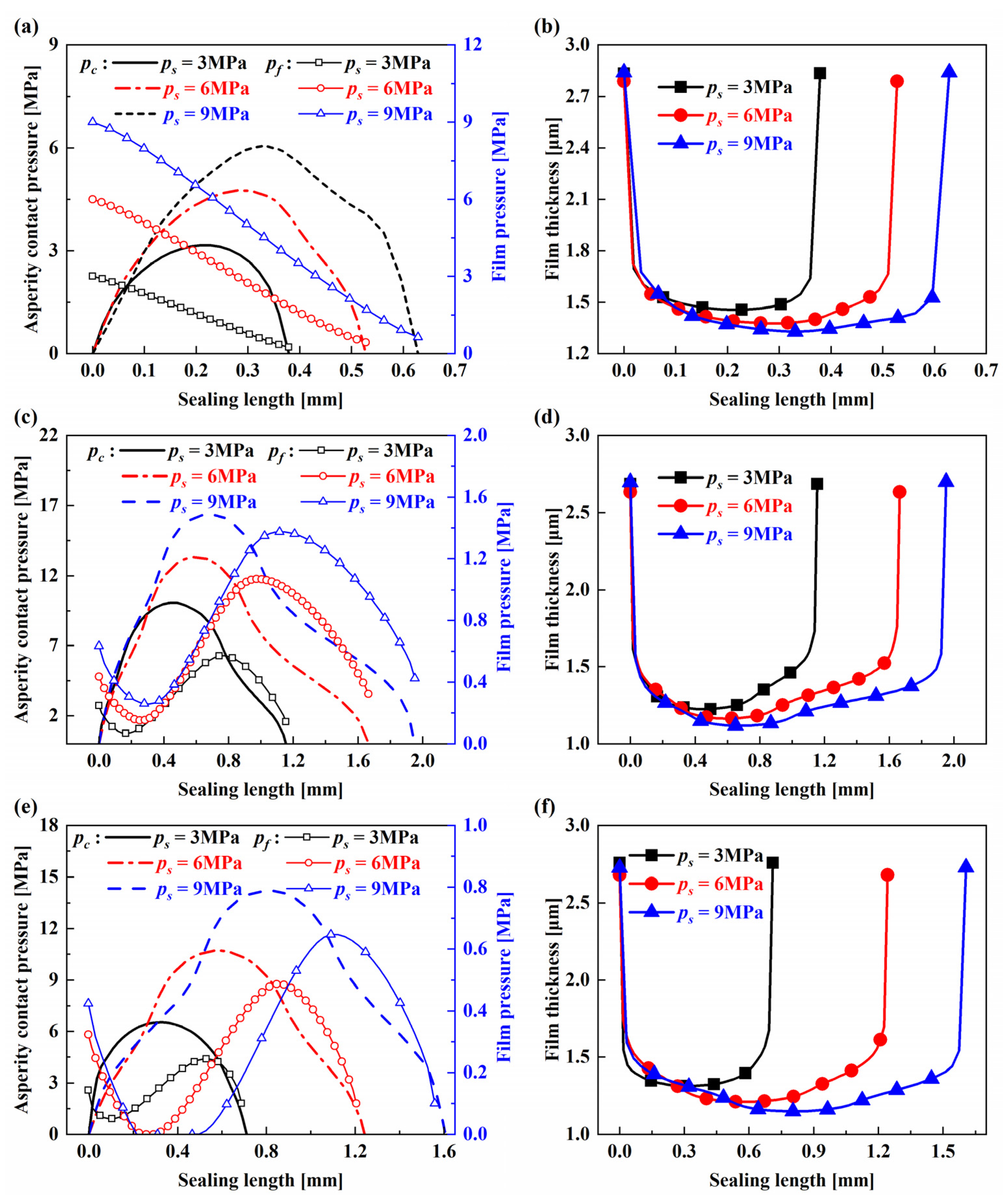
Figure 6 suggests the distributions of the asperity contact pressure, fluid pressure, and film thickness at different sealed pressure when u = 0.1 m/s and σ = 0.6 μm. From Figure 6a,c,e, with the increase of the fluid sealed pressure, the asperity contact pressure and fluid film pressure of the left lip, main lip, and right lip show similar change trends, respectively. The asperity contact pressure of the left lip gradually rises from the initial zero contact pressure to the peak value, and then decreases to zero towards the low-pressure fluid side, as shown in Figure 6a. Along the left sealing zone, the fluid film pressure gradually decreases from the sealed pressure fluid side to the first inter-lip region pressure on the low-pressure side. Figure 6c is the pressure distribution of the main lip. The asperity contact pressure shows a distribution law that first increases rapidly and then decreases slowly, while the fluid film pressure first decreases from the first inter-lip region fluid pressure to the wave trough value, then rises to the wave peak value, and finally decreases to the second inter-lip region pressure, showing an obvious asymmetric cosine function shape. Figure 6e is the pressure distribution of the right lip. The asperity contact pressure is similar basic distribution with that of static contact pressure, which shows the change law from quadratic function to Gaussian function, and the fluid film pressure also shows asymmetric cosine shape. When the sealed pressure is greater than 6 Mpa, the right lip cavitation occurs near the side from the second inter-lip region. It is shown that when the piston rod is extended in this process, the second inter-lip region fluid does not leak to the low-pressure fluid side of the piston seal through the right lip, which is similar to the research results of Yang [21]. The film thickness distributions of the left lip, main lip, and right lip are presented in Figure 6b,d,f, respectively. The film contact width increases significantly as the sealed pressure increases, while the film thickness in the three sealing zones are reduced to below 3σ, indicating that the sealing zone is in the mixed lubrication state [34].
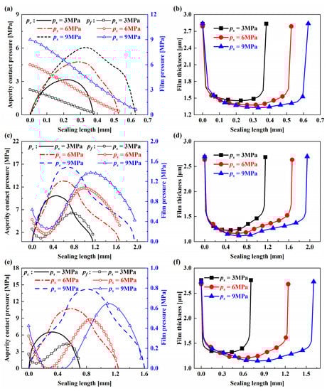
Figure 6.
Pressure and film thickness distributions with different sealed pressure: (a,c,e)pressure of the left lip, main lip, and right lip; (b,d,f) film thickness of the left lip, main lip, and right lip.
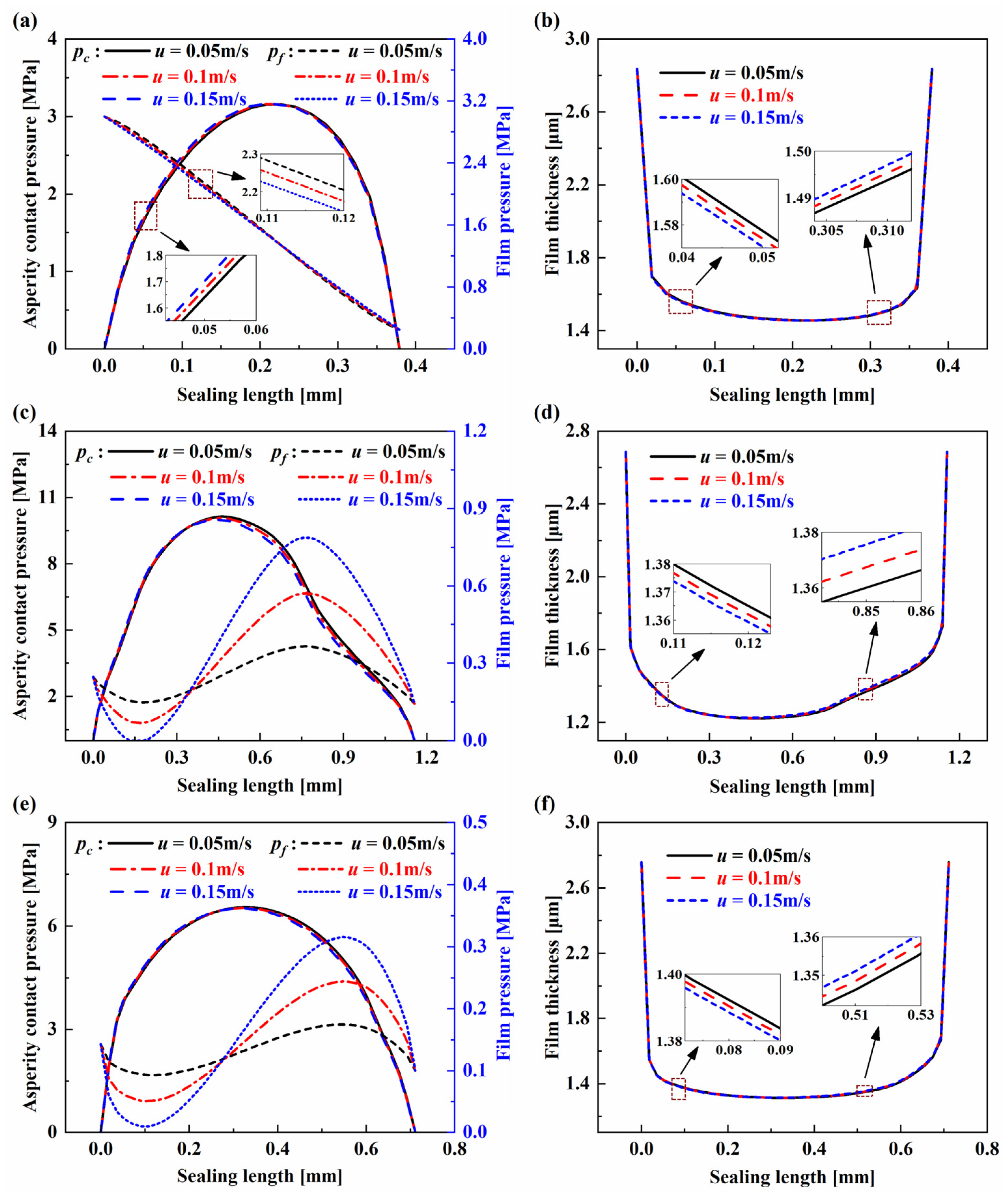
Figure 7 shows the distributions of asperity contact pressure, fluid pressure, and film thickness at different piston rod extension speeds when ps = 3 MPa and σ = 0.6 μm. From Figure 7a,c,e, when the piston rod maintains a certain speed, the fluid film pressure in the three seal lip regions presents an asymmetrical cosine function curve. The fluid film pressure of the left lip gradually transitions from the sealed pressure as the start pressure, and then to the fluid pressure in the first inter-lip region as the end pressure. However, the fluid film pressures of the main lip and the right lip presents an obvious cosine function distribution. The fluid pressure in the first and second inter-lip regions are as the start pressure, then after the sharp fluctuation of the wave trough and wave peak, and finally ends in the second inter-lip region and the low-pressure side, respectively. When the speed increases, the hydrodynamic effect in the sealing zone is enhanced, so that the trough amplitude of the fluid film pressure continues to decline, and the peak amplitude continues to rise. This calculation result is similar to the instroke conclusion of the rod seal studied by Yuan [7]. Meanwhile, it can be found from Figure 7c that when the speed increases to 0.15 m/s, the fluid film pressure of the main lip cavitation occurs at the wave trough near the first inter-lip region, indicating that there is a critical speed to prevent internal leakage of the seal. Figure 7b,d,f are the film thickness distributions of the left lip, main lip, and right lip, respectively. As the piston rod extension speed increases, the film thickness distribution curves almost coincide. Although the hydrodynamic effect increases with the piston rod speed, the asperity contact pressure accounts for a large proportion of the radial load balance. In addition, the hydrodynamic effect caused by a small range of speed is limited, which also shows that the DAS combined seal can still show better sealing performance when the speed is greater. At the same time, the film thickness at different speeds is less than 3σ in most of the sealing zone.
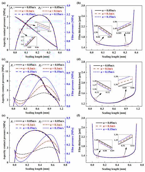
Figure 7.
Pressure and film thickness distributions with different piston speed: (a,c,e) pressure of the left lip, main lip, and right lip; (b,d,f) film thickness of the left lip, main lip, and right lip.
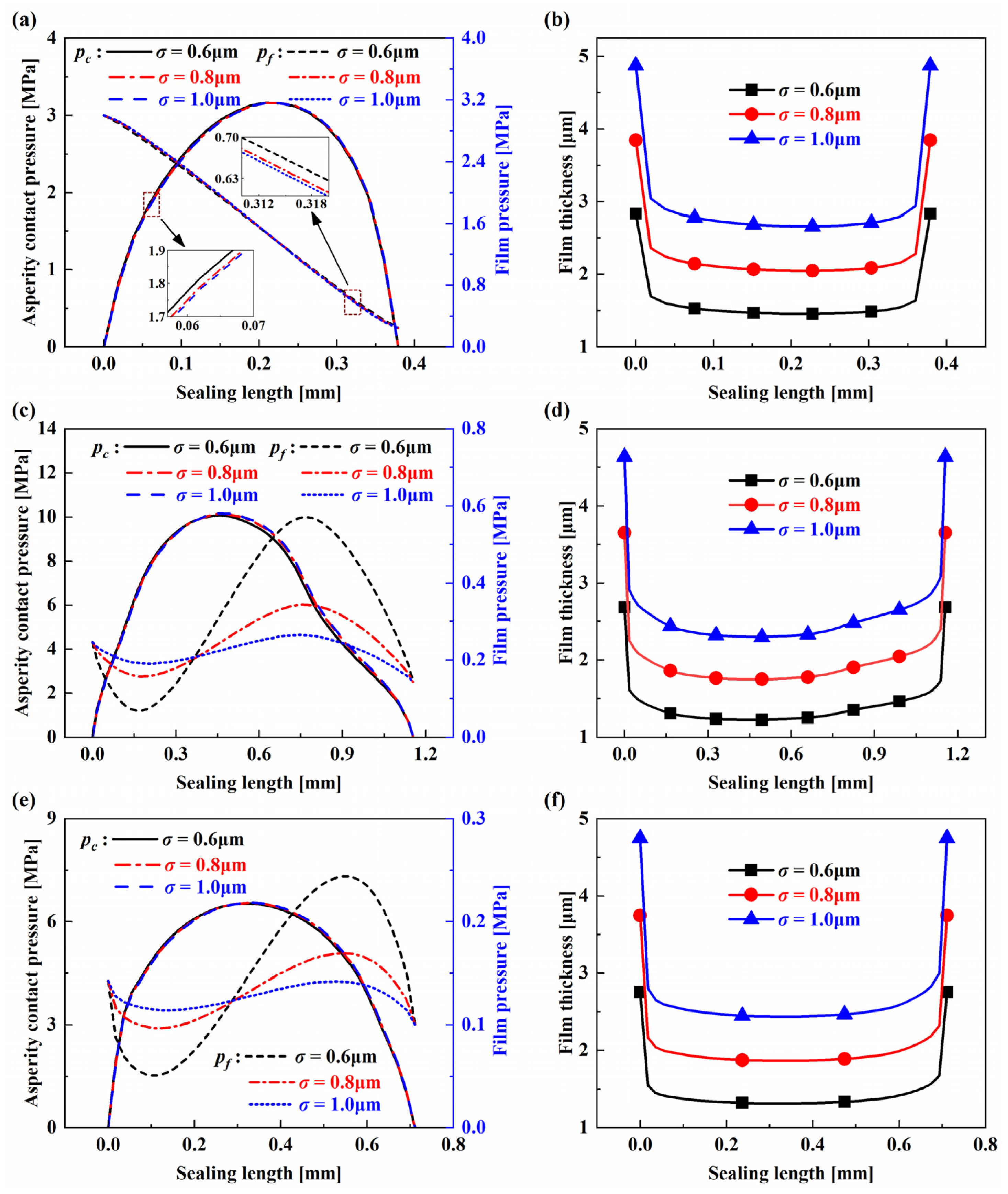
Figure 8 shows the distributions of asperity contact pressure, fluid pressure, and film thickness at different seal surface roughness when ps = 3 MPa and u = 0.1 m/s. From Figure 8a,c,e, the asperity contact pressure does not change obviously with the increasing roughness; the fluid film pressure gradually transitions from an asymmetric cosine function with obvious characteristics of wave valley and peak to a function curve with relatively stable fluctuation. It shows that there is a certain critical roughness value which can make the fluid film pressure distribution form a linear trend. Figure 8b,d,f are the film thickness distributions of the left lip, main lip, and right lip, respectively. It is clear that with increasing roughness, the film thickness presents an obvious increase trend. When the roughness is 0.8 μm, the film thickness of the left lip and the right lip is greater than 3σ, indicating that they are full film lubrication state, while the main lip is mixed lubrication state. Mainly because of that, the compression and sealing length of the three seal lips are different under the sealed pressure. When the roughness continues to increase to 1.0 μm, the state of the three sealing zones returns to the mixed lubrication state. It indicates that there is a critical roughness value, which can make the sealing zone transition from the mixed lubrication state to the full film lubrication state. Therefore, the effect of the seal roughness on the sealing performance cannot be ignored.
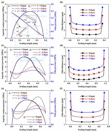
Figure 8.
Pressure and film thickness distributions with different surface roughness: (a,c,e) pressure of the left lip, main lip, and right lip; (b,d,f) film thickness of the left lip, main lip, and right lip.
4.2.2. Effects of Sealed Pressure and Piston Speed
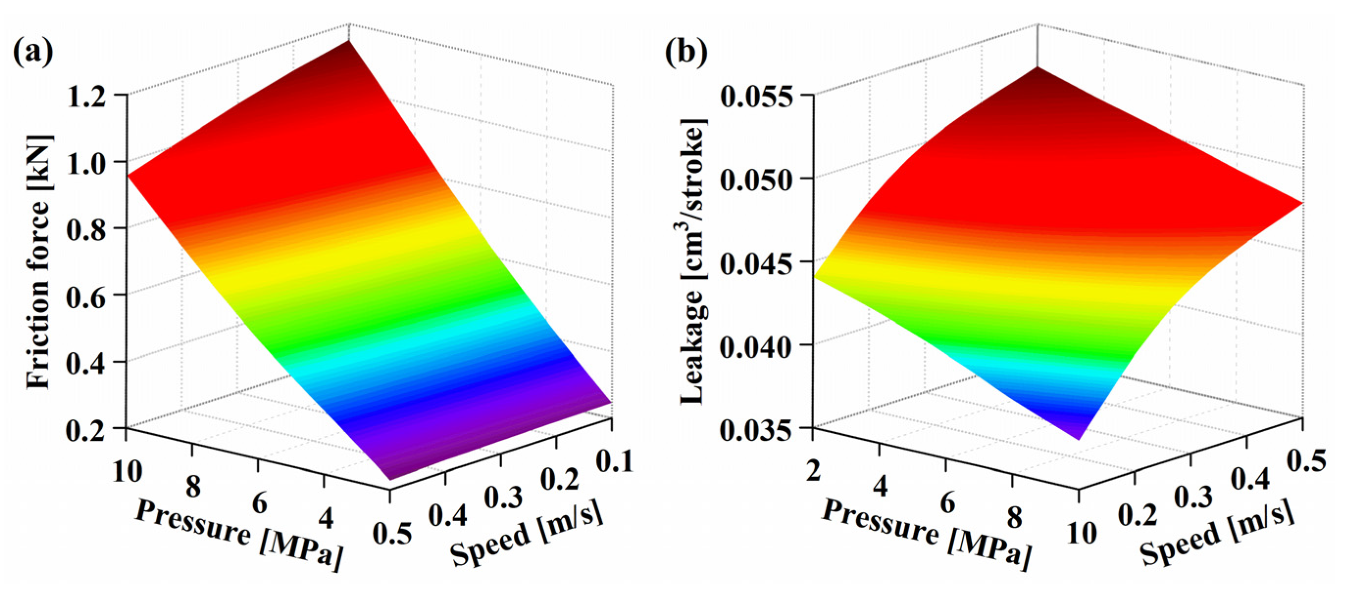
Figure 9 shows the combined effects of different sealed pressures and rod speeds on friction and internal leakage when σ = 0.6 μm. From Figure 9a, the friction force increases approximately linearly with the increasing fluid sealed pressure when the speed is a constant value. The static contact pressure increases with the increasing sealed pressure (see Figure 5), while the contact pressure plays a major role in the generation of the friction force, so the friction is proportional to the sealed pressure. When the sealed pressure is a fixed value, the friction force decreases with the increasing speed. This is because the friction force is mainly caused by the asperity contact body at low speed. The hydrodynamic effect and film thickness increase with the increasing speed, so the friction force decreases. At the same time, the friction force decreases gently with the increase of speed, as Ps < 4 MPa, while the friction force decreases obviously, as Ps > 4 MPa. This result is mainly due to the corresponding enhancement of the hydrodynamic effect with the increase of the sealed pressure. Figure 9b shows the trend of internal leakage. It is obvious that the internal leakage increases synchronously with the piston speed during the piston rod extension but decreases with the sealed pressure increase. The reason is because the higher the speed, the stronger the hydrodynamic effect, resulting in larger film thickness and internal leakage. During the piston rod extension process, the Couette flow to the high-pressure side on the cylinder inner wall becomes more evident with the increase of sealed pressure, while the pressure gradient on both sides of the seal causes the differential Poiseuille flow to the low-pressure side basically unchanged, so the internal leakage gradually decreases.

Figure 9.
Variation of friction force and fluid leakage with sealed pressure and piston speed: (a) friction force, (b) fluid leakage.
4.2.3. Effects of Sealed Pressure and Surface Roughness
Figure 10 shows the combined effects of different sealed pressures and roughness on friction and internal leakage when u = 0.5 m/s. From Figure 10a, the friction force increases with increasing roughness. This result suggests that the smooth surface of the seal is to the benefit of reducing friction. The friction force is more sensitive to changes of roughness, as σ < 0.8 μm. While the increasing gradient of frictional force decreases substantially, as σ > 0.8 μm. This phenomenon shows that there is a critical roughness near 0.8 μm. When the seal roughness equals the critical value, the friction force is greatly reduced, and the sealing performance is significantly optimized. Meanwhile, it can be found that when the roughness is constant, the increase of the fluid sealed pressure leads to a sharp increase in the friction force, which is basically similar to the outline in Figure 9a, indicating that the sealed pressure is one of the important factors causing the friction force. Figure 10b shows the variation of internal leakage with sealed pressure and roughness. As shown in the figure, the internal leakage presents an obvious nonlinear increase trend with the roughness increase. When the roughness is small, the internal leakage decreases gently with the sealed pressure increase, whereas when the roughness is large, the internal leakage decreases sharply. The main reason is that with the roughness increase, the sealing gap and fluid film thickness increase accordingly, so that more fluid passes through the sealing interface and the internal leakage increases.
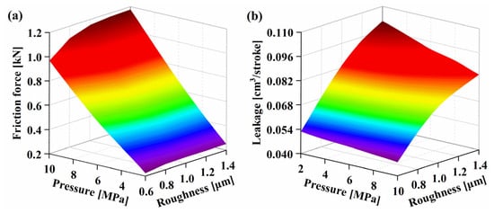
Figure 10.
Variation of friction force and fluid leakage with sealed pressure and surface roughness: (a) friction force, (b) fluid leakage.
4.2.4. Effects of Piston Speed and Surface Roughness
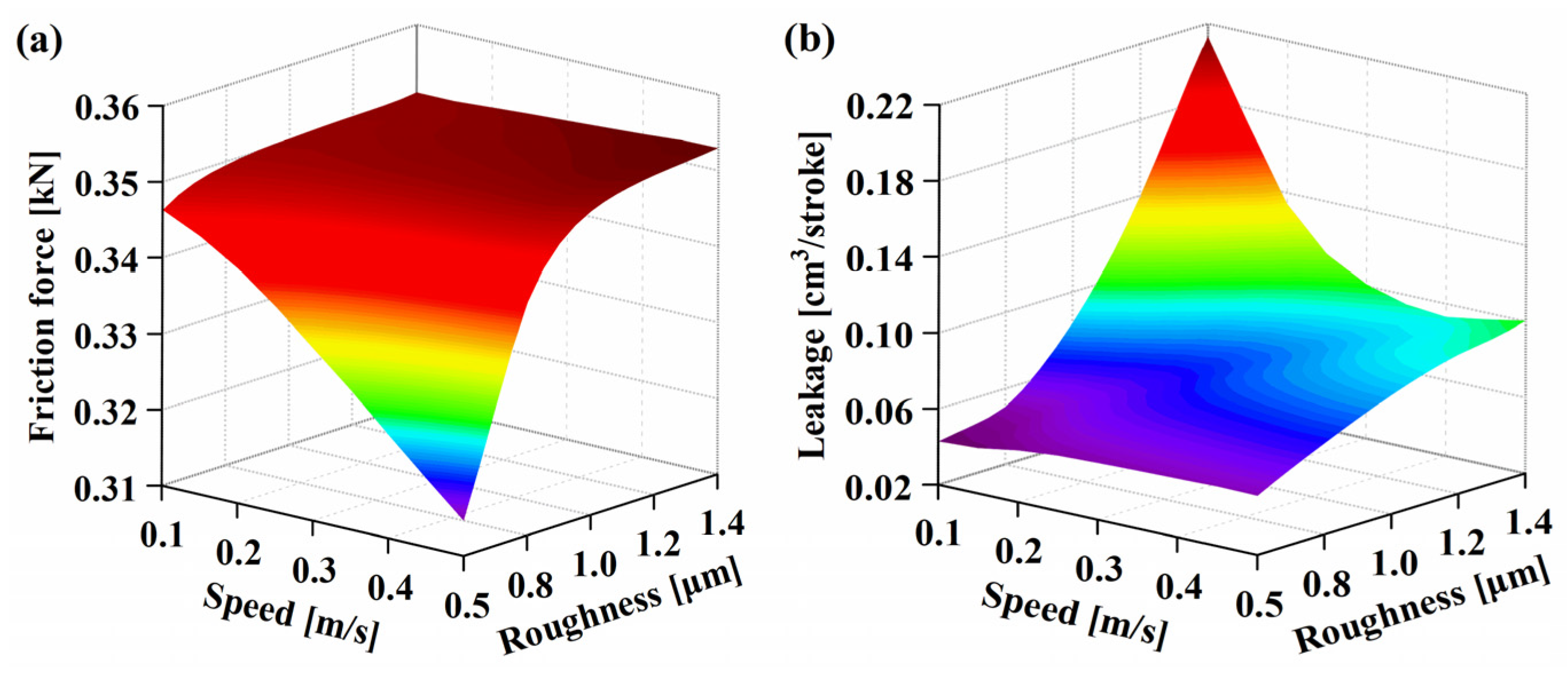
Figure 11 shows the combined effects of different rod speeds and roughness on friction and internal leakage when ps = 3 MPa. From Figure 11a, when σ = 0.6 μm the piston rod speed increases from 0.1 m/s to 0.5 m/s, and the friction force decreases from 346 N to 313 N. However, the friction force has no obvious change with the speed increase when σ = 1.4 μm. The reason is that when the roughness is large, the friction force is mainly caused by the asperity contact body of the sealing interface. While the hydrodynamic pressure effect is very weak, the piston rod speed has little effect on friction. However, when the roughness is relatively small, the hydrodynamic pressure effect caused by the speed is relatively strong, and the piston rod speed has a great influence on the friction force. The variation of internal leakage with the speed and roughness is shown in Figure 11b, the internal leakage keeps a monotonically increasing trend with the roughness increase when the speed is a certain value, which is consistent with the previous conclusion. As roughness ranges from 0.6 μm to 0.8 μm, the internal leakage increases with the increasing speed. When the roughness ranges from 1.0 μm to 1.4 μm, the internal leakage shows a concave variation rule with the speed increase. Therefore, it can be inferred that there is a critical roughness in this roughness range. When the roughness is less than this critical roughness, the internal leakage increases monotonically. When the roughness is greater than this value, the internal leakage tends to decrease.
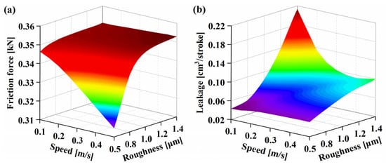
Figure 11.
Variation of friction force and fluid leakage with piston speed and surface roughness: (a) friction force, (b) fluid leakage.
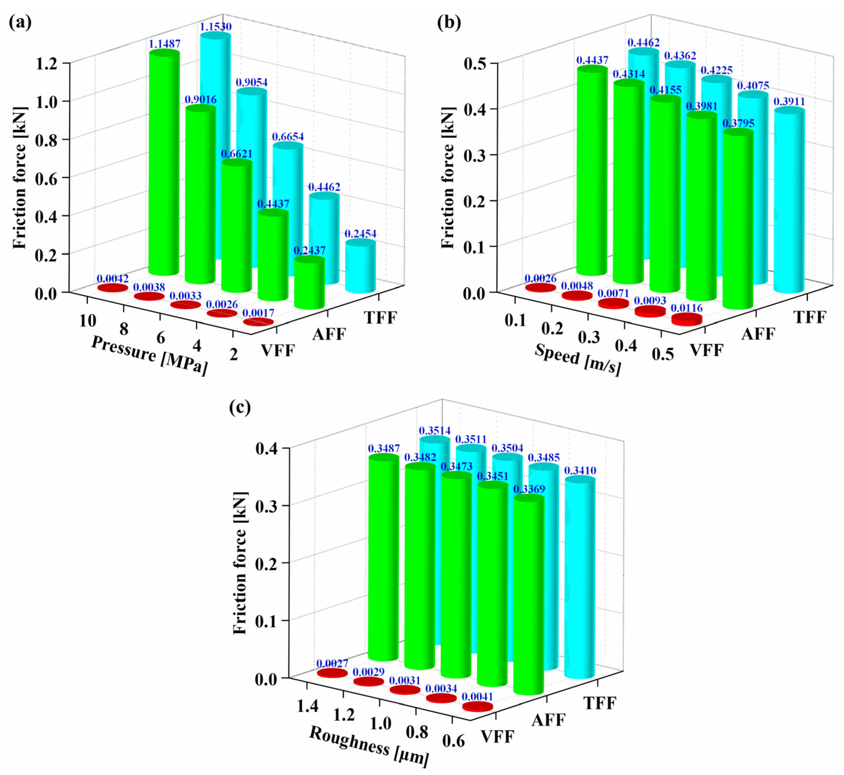
Figure 12 shows the influence of sealed pressure, speed, and roughness on the variation of friction force during piston rod extension, respectively. For sealed pressure, see Figure 12a, where u = 0.1 m/s and σ = 0.6 μm. The viscous friction force increases slightly with sealed pressure, but the asperity friction force and total friction force increase significantly. For speed, see Figure 12b, where ps = 4 MPa and σ = 0.6 μm. With increasing speed, the total friction force and the asperity friction force decrease, while the corresponding viscous friction force increases. For roughness, see Figure 12c, where ps = 4 MPa and u = 0.2 m/s. It is observed that the friction force is positively associated with roughness, which is consistent with the effect of sealed pressure on friction force. To sum up, in order to meet the current performance requirements for high-pressure and high-speed of hydraulic cylinders and reduce the wear and damage by friction on the seal, it is necessary to ensure that the surface roughness of the seal is as small as possible when producing the hydraulic cylinder piston seal.
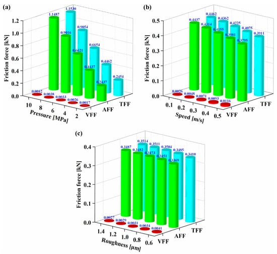
Figure 12.
Variation of total friction force (TFF), asperity friction force (AFF) and viscous friction force (VFF) with (a) sealed pressure, (b) rod speed, and (c) surface roughness.
5. Experimental Study
5.1. Experimental Apparatus
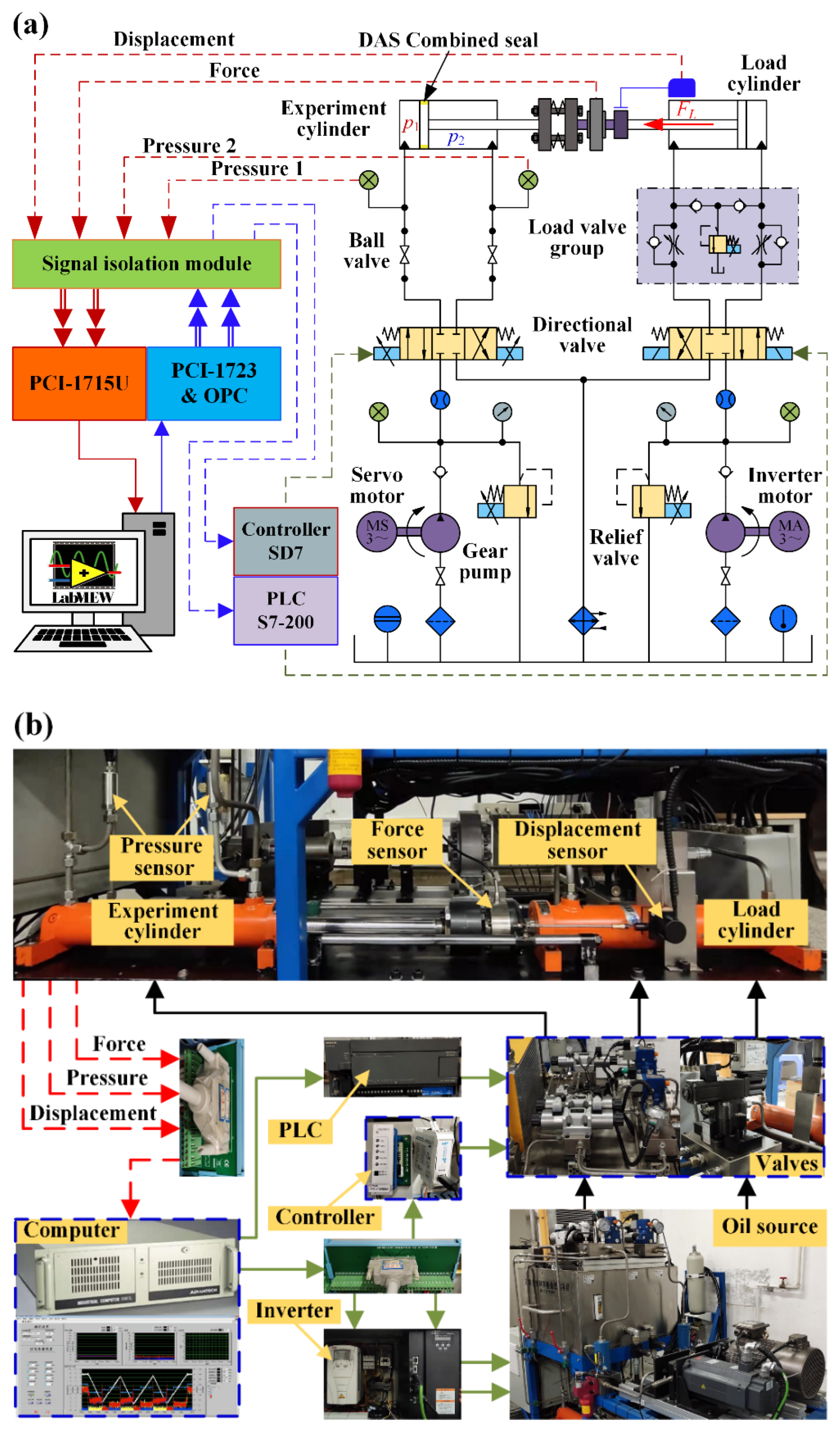
To be able to verify the impact of relevant factors on the sealing performance, the dynamic friction caused by the seal was experimentally studied. Figure 13a presents the system principle of the test bench. The whole hydraulic system is driven with a synchronous servo motor and an asynchronous inverter motor to drive two gear pumps to supply oil to the test circuit and the load circuit separately. The same type of experiment cylinder and the load cylinder are connected by bolts, and the relevant parameters of the hydraulic cylinder are shown in Table 2. The system pressure of the test circuit can be set by the safety relief valve, the piston rod extension speed can be adjusted by the ball valve of the experiment cylinder rodless chamber, and the load cylinder load force can be adjusted by the load valve group. Test the two pressure sensors at the inlet and outlet of the experiment cylinder to real-time acquisition and record the pressure data of the two oil chambers. The displacement and load force of the hydraulic cylinder are measured by the displacement sensor and force sensor, respectively. Advantech PCI-1715U high-speed acquisition card is used to collect the measurement analog signals of all sensors. Meanwhile, the test data are displayed and saved in real-time by using LabVIEW programming software on an industrial computer. Figure 13b shows the actual composition of the test bench.
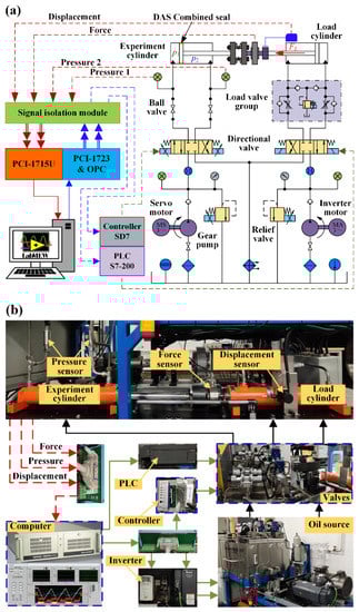
Figure 13.
Experiment platform: (a) Structural schematic diagram; (b) actual composition diagram.
5.2. Measurement Principle
The dynamic friction force generated by the experiment cylinder during the reciprocating motion satisfies the dynamic equilibrium equation, so the friction force is:
where p1, p2 are the pressure of the rodless chamber and the rod chamber, A1, A2 are the area of the rodless chamber and the rod chamber, FL is the load force, m is the sum of the masses of the piston, piston rod, and other connectors, and a is the acceleration of the rod/piston during extension (for steady-state conditions, (a = 0)).
5.3. Experimental Results
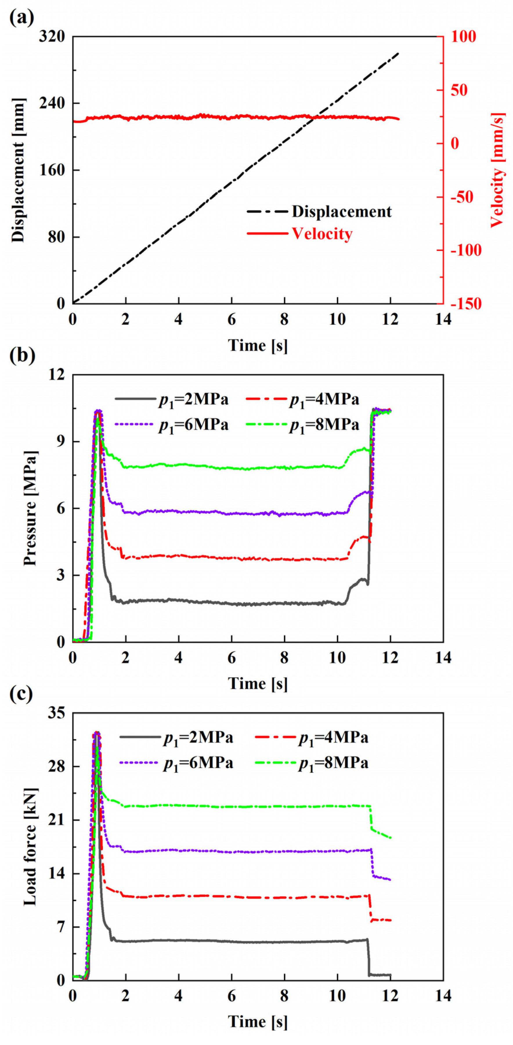
Figure 14 shows the relevant experimental test data for the friction force at different system pressures. Figure 14a shows the displacement and speed distribution curves during the piston rod extension of the experiment cylinder, where the steady-state speed is 0.025 m/s and the extension displacement is 300 mm. The experiment cylinder rodless chamber pressure is the system pressure (sealed pressure) during the piston rod extension. The rod chamber is connected to the tank, and its pressure is atmospheric pressure. Figure 14b,c are the variation curves of the experiment cylinder rodless chamber pressure and the load cylinder load force, respectively. It is obvious that the experiment cylinder system pressure increases with the increase of the load cylinder load force.
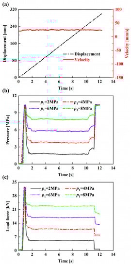
Figure 14.
Experimental data: (a) Piston rod displacement; (b) rodless chamber pressure; (c) load force.
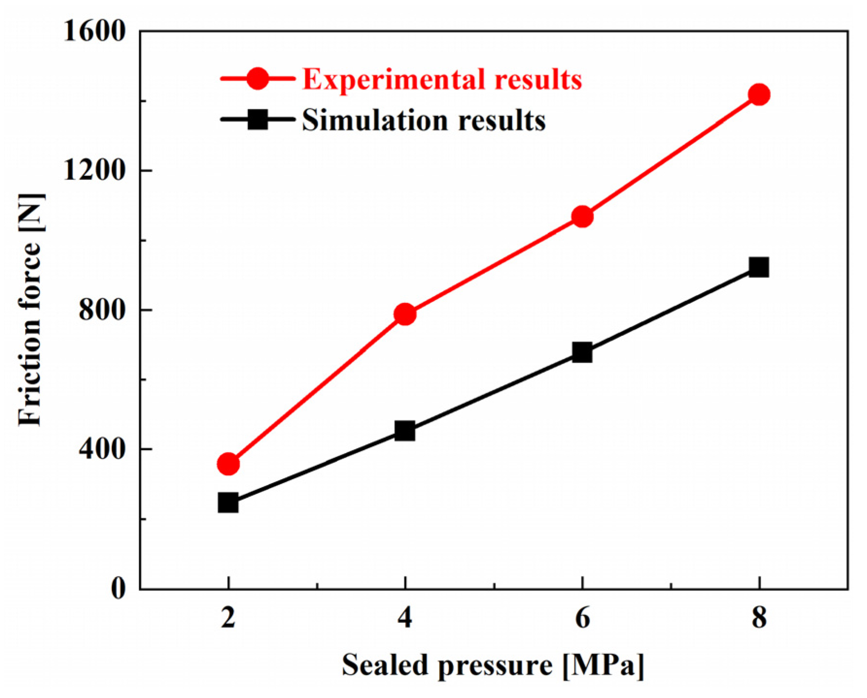
Figure 15 shows the comparison of experimental and simulation results at different sealed pressures when the piston rod extension speed is 25 mm/s. It can be observed from the figure that the friction force variation trend of the experiment and simulation is consistent as a whole, and the friction force increases linearly as well as the increasing sealed pressure. Meanwhile, the experimental results are larger than the simulation results. There are two main reasons: on the one hand, the simulation only calculates the piston seal, and the friction force of the experiment is the total friction force of the piston seal and the rod seal; on the other hand, there is an eccentric load phenomenon during the experimental loading process.
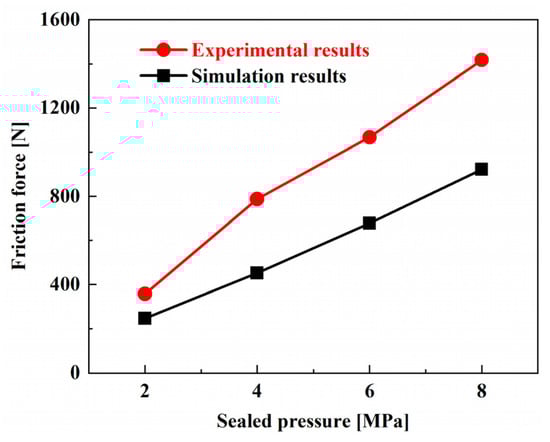
Figure 15.
Friction force comparison between the experiment and simulation.
6. Conclusions
A novel M-EHL numerical model of multi-lip reciprocating seals was established based on DAS combined seal. The influence of different sealed pressure, piston rod speed, and seal surface roughness on the sealing performance are researched under steady-state conditions. Through the discussion and analysis of the contact pressure, film thickness, leakage, and friction in the sealing zone, the sealing performance in the process of piston rod extension is simulated. The experimental results are consistent with the simulation results in the variation trend of friction. From the numerical analysis, some multi-lip seal characteristics of the DAS combined seal are obtained as follows:
- (1)
- In mixed lubrication state, the asperity contact pressure increases obviously with the increase of sealed pressure, while the film thickness decreases, and the asperity contact pressure of the main lip is the largest. It shows that during the high-pressure service of the hydraulic cylinder, the main lip will produce more wear and accelerate the failure of the seal. With the increase of the piston rod speed, the asperity contact pressure decreases relatively, and the increase of the film thickness is not obvious, while the asperity contact pressure and the film thickness both increase with the increase of the seal surface roughness.
- (2)
- With the increase of piston rod speed and seal surface roughness, the leakage increases. When the seal surface roughness is within a certain range, the leakage decreases significantly with the sealed pressure increase. Therefore, to minimize internal leakage, the hydraulic cylinder piston seal surface roughness should be selected reasonably under the condition that the hydraulic cylinder meets the requirements of working conditions.
- (3)
- When the pre-compression amount of the seal is constant, the friction force is mainly determined by the sealed pressure. With the increase of sealed pressure, the friction force of the sealing zone increases significantly. Although increasing the piston rod speed and seal surface roughness can increase the film thickness, the viscous friction force is relatively weak, so the piston rod speed and seal surface roughness have little influence on the total friction force.
Through the above analysis, the numerical model in this paper can be used for the analysis and design of the sealing performance of the multi-lip reciprocating seals. However, the model does not consider the effect of temperature changes on the sealing performance. Therefore, further studies are needed to study the influence of the thermal elastohydrodynamic coupling effect on sealing performance. In addition, the experimental equipment needs to be improved to accurately measure seal friction.
Author Contributions
Conceptualization, D.C. and L.G.; methodology, D.C.; software, D.C.; validation, D.C., L.G. and Y.S.; formal analysis, L.G.; investigation, D.C.; resources, Y.S.; data curation, D.C.; writing—original draft preparation, D.C.; writing—review and editing, L.G.; supervision, L.G.; project administration, L.G. and Y.S. All authors have read and agreed to the published version of the manuscript.
Funding
This research was funded by the National Natural Science Foundation of China (grant no. 51675399), and the Science and Technology Foundation of Xi’an University of Architecture and Technology, China (grant no. ZR19059).
Data Availability Statement
Not applicable.
Conflicts of Interest
The authors declare no conflict of interest.
Nomenclature
| C10, C01, d | Moony–Rivlin coefficients |
| Ds | Seal outside diameter |
| ds | Seal inside diameter |
| E | Elastic modulus |
| F | Cavitation index |
| Ff | Friction force |
| FL | Load force of the hydraulic cylinder |
| f | Friction coefficient for asperity contact |
| h | Fluid film thickness |
| H | Dimensionless average film thickness, h/σ |
| Hs | Dimensionless static film thickness, hs/σ |
| HT | Dimensionless average truncated film thickness, hT/σ |
| I1, I2 | Green–Lagrange strain invariant |
| J | Elastic volume ratio |
| K | Influence coefficient matrix |
| L | Contact length of sealing zone |
| Lstroke | Piston/rod stroke length |
| pa | Ambient pressure |
| Pc | Dimensionless asperity contact pressure, pc/E |
| Pf | Dimensionless fluid film pressure, pf/pa |
| Dimensionless fluid pressure in current iterated step | |
| Dimensionless fluid pressure in last iterated step | |
| Pi1, Pi2 | Pressure in the first and second inter-lip region |
| Pl | Dimensionless pressure in low-pressure side, pl/pa |
| Ps | Dimensionless sealed pressure, ps/pa |
| Psc | Dimensionless static contact pressure, psc/E |
| Q | Flow rate per stroke |
| Dimensionless flow rate, | |
| R | Radius of asperities |
| U | Dimensionless piston rod speed, |
| WM−R | Strain-energy function |
| Ws | Width of the seal |
| Dimensionless coordinate parallel to the fluid film thickness, x/L | |
| z | Dimensionless coordinate normal to the fluid film thickness |
| Dimensionless pressure–viscosity coefficient, αpa | |
| ξ | |
| Φ | Fluid pressure/density function |
| ϕf, ϕfs, ϕfp | Shear stress factors |
| ϕs.c.x, ϕxx | flow factor |
| η | Asperity density |
| μ0 | Viscosity at atmospheric pressure |
| v | Poisson’s ratio |
| ρf | Fluid density |
| Dimensionless density, ρ/ρf | |
| Dimensionless RMS roughness of the seal, σR1/3η2/3 | |
| Dimensionless viscous shear stress, | |
| Dimensionless asperity shear stress, |
Appendix A
- Fluid Mechanics
The mass conservation equation is also known as the continuity equation, and its equation is:
The reciprocating speed of the piston is along the x-axis, the circumferential direction of the seal ring is along the y-axis, and the film thickness is along the z-axis. Since the film thickness is at the micron level, the fluid flow along the film thickness direction (z-axis) can be ignored. Reynolds equation is used to describe the flow in the sealing zone, the Equation (A1) can be converted to:
where xq and yq are the flow per unit time along the x and y directions, respectively.
Assuming that the sealing zone is an incompressible Newtonian fluid, according to the load balance condition in the x-direction, the flow velocity of the fluid micro-elements along the x and y directions are:
The unit time flow in the x and y directions are:
Substituting Equations (A5) and (A6) into Equation (A2):
The time effect is ignored, the steady-state model is:
The average Reynolds equation considering the roughness effect is [29]:
The Reynolds equation considering the cavitation effect is [27]:
where, pcav is cavitation pressure.
Combining Equations (A9) and (A10), the Reynolds equation considering roughness and cavitation effects can be obtained as:
Since the piston reciprocates relative to the cylinder at a speed u. Therefore, u1 = u, u2 = 0, then the Equation (A11) can be converted into the 1-D Reynolds equation as:
Dimensionless transformation of Equation (A12) can obtain Equation (2).
- Contact mechanics
Figure A1 shows the contact between an asperity surface (elastic surface) and a smooth surface (rigid surface). In the figure, d is the distance between the smooth surface and the midline of the asperity surface, z is the distance between the asperity peak and the midline of the asperity surface, and δ is the deformation after the contact between the asperity peak and the smooth surface.
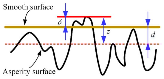
Figure A1.
Schematic of the contact between asperity surface and smooth surface.
Figure A1.
Schematic of the contact between asperity surface and smooth surface.

According to Hertzian contact theory, the contact area Ai and contact load Fi of the i-th asperity peak can be expressed as:
where E′ is the equivalent elastic modulus of the two surfaces. The elastic modulus of the seal ring and cylinder are Es and Ec, and the Poisson’s ratio are vs and vc, respectively. So,
The asperity peak density on the nominal contact area An is defined as η. Assuming that the seal surface roughness conforms to Gaussian distribution, the probability density function can be expressed as:
When the asperity surfaces are in contact (i.e., z > d), the total contact area Ac is expressed:
The total contact load Ftol is:
Combining Equations (A15) to (A18), the contact pressure of asperity peak is:
Equation (7) can be obtained after dimensionless pc in Equation (A19).
References
- Nikas, G. Eighty years of research on hydraulic reciprocating seals: Review of tribological studies and related topics since the 1930s. Proc. Inst. Mech. Eng. Part J J. Eng. Tribol. 2010, 224, 1–23. [Google Scholar] [CrossRef]
- White, C.; Denny, D.; Britain, G. The Sealing Mechanism of Flexible Packings; HM Stationery Office: London, UK, 1948; pp. 35–62. [Google Scholar]
- Karaszkiewicz, A. Hydrodynamic lubrication of rubber seals for reciprocating motion; leakage of seals with an O-ring. Tribol. Int. 1988, 21, 361–367. [Google Scholar] [CrossRef]
- Kaneta, M.; Todoroki, H.; Nishikawa, H.; Kanzaki, Y.; Kawahara, Y. Tribology of flexible seals for reciprocating motion. J. Tribol. 2000, 122, 787–795. [Google Scholar] [CrossRef]
- Öngün, Y.; André, M.; Bartel, D.; Deters, L. An axisymmetric hydrodynamic interface element for finite-element computations of mixed lubrication in rubber seals. Proc. Inst. Mech. Eng. Part J J. Eng. Tribol. 2008, 222, 471–481. [Google Scholar] [CrossRef]
- Peng, C.; Ouyang, X.; Zhu, Y.; Guo, S.; Zhou, Q.H.; Yang, H.Y. Investigation into the influence of stretching on reciprocating rod seals based on a novel 3-D model vs axisymmetric model. Tribol. Int. 2018, 117, 1–14. [Google Scholar] [CrossRef]
- Yuan, X.; Wang, J.; Lian, Z.; Wang, G. Partial lubrication modeling of reciprocating rod seals based on a developed EHL method. Tribol. Int. 2021, 153, 106585. [Google Scholar] [CrossRef]
- Salant, R.; Yang, B.; Thatte, A. Simulation of hydraulic seals. Proc. Inst. Mech. Eng. Part J J. Eng. Tribol. 2010, 224, 865–876. [Google Scholar] [CrossRef]
- Crudu, M.; Fatu, A.; Cananau, S.; Hajjam, M.; Pascu, A.; Cristescu, C. A numerical and experimental friction analysis of reciprocating hydraulic ‘U’ rod seals. Proc. Inst. Mech. Eng. Part J J. Eng. Tribol. 2012, 226, 785–794. [Google Scholar] [CrossRef]
- Huang, Y.; Salant, R.F. Numerical analysis of a hydraulic rod seal: Flooded vs. starved conditions. Tribol. Int. 2015, 92, 577–584. [Google Scholar] [CrossRef]
- Gadari, M.E.; Hajjam, M. Effect of the Grooved Rod on the Friction Force of U-Cup Hydraulic Rod Seal with Rough Lip. Tribol. Trans. 2018, 61, 661–670. [Google Scholar] [CrossRef]
- Wang, J.; Li, Y.; Lian, Z. Numerical Investigations on the Sealing Performance of a Reciprocating Seal Based on the Inverse Lubrication Method. J. Tribol. 2019, 141, 112201. [Google Scholar] [CrossRef]
- Nikas, G. Elastohydrodynamics and Mechanics of Rectangular Elastomeric Seals for Reciprocating Piston Rods. J. Tribol. 2003, 125, 60–69. [Google Scholar] [CrossRef]
- Nikas, G.; Almond, R.; Burridge, G. Experimental Study of Leakage and Friction of Rectangular, Elastomeric Hydraulic Seals for Reciprocating Motion from −54 to +135 °C and Pressures from 3.4 to 34.5 MPa. Tribol. Trans. 2014, 57, 846–865. [Google Scholar] [CrossRef]
- Bhaumik, S.; Kumaraswamy, A.; Guruprasad, S.; Bhandari, P. Investigation of friction in rectangular Nitrile-Butadiene Rubber (NBR) hydraulic rod seals for defence applications. J. Mech. Sci. Technol. 2015, 29, 4793–4799. [Google Scholar] [CrossRef]
- Mao, J.; Wang, W.; Liu, Y. Experimental and theoretical investigation on the sealing performance of the combined seals for reciprocating rod. J. Mech. Sci. Technol. 2012, 26, 1765–1772. [Google Scholar] [CrossRef]
- Peng, C.; Guo, S.; Ouyang, X.; Zhou, Q.; Yang, H. Mixed Lubrication Modeling of Reciprocating Seals Based on a Developed Multiple-Grid Method. Tribol. Trans. 2018, 61, 1151–1161. [Google Scholar] [CrossRef]
- Xiang, C.; Guo, F.; Jia, X.; Wang, Y.; Huang, X. Thermo-elastohydrodynamic mixed-lubrication model for reciprocating rod seals. Tribol. Int. 2019, 140, 105894. [Google Scholar] [CrossRef]
- Wang, B.; Peng, X.; Meng, X. Simulation of the effects of non-Newtonian fluid on the behavior of a step hydraulic rod seal based on a power law fluid model. J. Zhejiang Univ. Sci. A 2018, 19, 824–842. [Google Scholar] [CrossRef]
- Ran, H.; Wang, S.; Liu, D. A multiscale wear model for reciprocating rod stepseal under mixed lubricating conditions based on linear elasticity. Proc. Inst. Mech. Eng. Part J J. Eng. Tribol. 2020, 235, 161–180. [Google Scholar] [CrossRef]
- Yang, B.; Salant, R. A Numerical Model of a Reciprocating Rod Seal With a Secondary Lip. Tribol. Trans. 2008, 51, 119–127. [Google Scholar] [CrossRef]
- Prati, E.; Strozzi, A. A Study of the Elastohydrodynamic Problem in Rectangular Elastomeric Seals. J. Tribol. 1984, 106, 505–512. [Google Scholar] [CrossRef]
- Dragoni, E.; Strozzi, A. Analysis of an Unpressurized, Laterally Restrained, Elastomeric O-Ring Seal. J. Tribol. 1988, 110, 193–200. [Google Scholar] [CrossRef]
- Ogden, R. Large Deformation Isotropic Elasticity: On the Correlation of Theory and Experiment for Compressible Rubberlike Solids. Proc. R. Soc. Lond. A 1972, 328, 567–583. [Google Scholar] [CrossRef]
- Rivlin, R. Large elastic deformations of isotropic materials IV. further developments of the general theory. Philos. Trans. R. Soc. Lond. A 1948, 241, 379–397. [Google Scholar]
- Zhang, J.; Han, C.; Liang, Z. Physics of failure analysis of power section assembly for positive displacement motor. J. Loss Prev. Process Ind. 2016, 44, 414–423. [Google Scholar] [CrossRef]
- Payvar, P.; Salant, R. A Computational Method for Cavitation in a Wavy Mechanical Seal. J. Tribol. 1992, 114, 199–204. [Google Scholar] [CrossRef]
- Salant, R.; Maser, N.; Yang, B. Numerical Model of a Reciprocating Hydraulic Rod Seal. J. Tribol. 2007, 129, 91–97. [Google Scholar] [CrossRef]
- Patir, N.; Cheng, H. An Average Flow Model for Determining Effects of Three-Dimensional Roughness on Partial Hydrodynamic Lubrication. J. Lubr. Technol. 1978, 100, 12–17. [Google Scholar] [CrossRef]
- Patir, N.; Cheng, H. Application of Average Flow Model to Lubrication Between Rough Sliding Surfaces. J. Lubr. Technol. 1979, 101, 220–229. [Google Scholar] [CrossRef]
- Greenwood, J.; Williamson, J. Contact of nominally flat surfaces. Proc. R. Soc. Lond. A 1966, 295, 300–319. [Google Scholar]
- EI Gadari, M.; Fatu, A.; Hajjam, M. Shaft roughness effect on elasto-hydrodynamic lubrication of rotary lip seals: Experimentation and numerical simulation. Tribol. Int. 2015, 88, 218–227. [Google Scholar] [CrossRef]
- Streator, J. A model of mixed lubrication with capillary effects. Tribol. Ser. 2002, 40, 121–128. [Google Scholar]
- Schmidt, T.; André, M.; Poll, G. A transient 2D-finite-element approach for the simulation of mixed lubrication effects of reciprocating hydraulic rod seals. Tribol. Int. 2010, 43, 1775–1785. [Google Scholar] [CrossRef]

Publisher’s Note: MDPI stays neutral with regard to jurisdictional claims in published maps and institutional affiliations. |
© 2022 by the authors. Licensee MDPI, Basel, Switzerland. This article is an open access article distributed under the terms and conditions of the Creative Commons Attribution (CC BY) license (https://creativecommons.org/licenses/by/4.0/).