Abstract
A rotor that can realize individual blade pitch control was designed. This paper focuses on finding the trend of helicopter vibration loads after applying multiple high-order harmonic control. The Glauert inflow model was introduced to calculate the induced velocity of rotor blades in a rotor disk plane, and the Leishman Beddoes (L-B) unsteady dynamic model was employed to calculate the aerodynamic forces of each section of a rotor blade. It was found that the influence of each high-order harmonic control on individual blade vibration load reduction is similar in different advanced ratios. After these calculations, the genetic algorithm was used to calculate the best combination of amplitude and phase of the higher order harmonic under a specific flight state. Under the effect of high harmonic input, the vibration loads of the hub could be reduced by about 65%. These results can be theoretically applied to design control law to reduce helicopter vibration loads.
1. Introduction
Dynamic loads at helicopter rotor hubs are one of the main vibration sources of helicopters. Reducing rotor vibration loads is an important approach to helicopter vibration suppression. Centrifugal pendulums, double-wire pendulums and other passive dynamic vibration absorbers were installed on helicopters in the past to reduce rotor vibration loads []. With the continuous development of computer technology, sensing technology and control technology, active control methods have become a research hotspot. These methods mainly include high-order harmonic control (HHC), individual blade control (IBC), active flap control (AFC) [], active torsion control (ATC) [] and active control of structural response (ACSR) [].
Individual blade control used to reduce helicopter vibration loads has been investigated and proven successful in recent literatures, which is a new method developed from HHC. HHC reduces vibration load components corresponding to the passing frequency of the rotor system by applying an excitation to the non-rotating ring of the swashplate []. However, IBC is more precise than HHC in theory, which can individually apply HHC to targeted blades. It can replace the traditional helicopter swashplate on the structure, as shown in Figure 1.
Figure 1.
Helicopter individual blade control.
Between 1977 and 1985, the Ham team at the Massachusetts Institute of Technology (MIT) conducted an early experimental study of IBC [,]. In 2001, Sikorsky and NASA carried out a full-scale wind tunnel test to find the influence of IBC on the vibration level of a UH-60 helicopter []. In 2008, a group of German scientists headed by Fuerst applied practically on the basis of single blade control and proposed the concept of an electro-mechanical-actuator (EMA) rotor system []. In an EMA, a servo motor is installed in each arm of the rotor system to reduce rotor vibration loads. An EMA system implements the first-order periodic pitch control of the blades and high-order harmonic control of a single blade through the servo motor motion control. In September 2015, the DLR completed the first wind tunnel test of its Multiple Swashplate System. During these tests, the potential of this new active rotor control system to effectively reduce noise, vibrations and power consumption using several IBC strategies was successfully demonstrated on two different model rotors without using actuators in the rotating frame [].
Genetic algorithm (GA) is a random search method derived from the evolutionary law of “survival of the fittest, survival of the fittest” in the biological world []. It has been widely used in combinatorial optimization, signal processing, machine learning and other fields [,,]. The genetic algorithm regards the solution set of the problem as a population, and continuously uses genetic operators to combine individuals in the population to generate a new generation of candidate solution sets and selects the best solution from the population according to certain criteria during the iteration process, until the convergence condition is satisfied [,].
Although the researchers have conducted much experimentation on IBC, the number of tests that can be performed at that time is limited and finding the parameters of optimal amplitudes and phases of multiple harmonics to reduce vibration loads in this limited number of trials is difficult and expensive. The purpose of the study is to analyze the influence of IBC on helicopter hub vibration loads reduction. This study gives some analysis details on how to calculate the influence of IBC on hub vibration loads. This study presents the optimum control of selective order harmonics and their combinations in order to reduce helicopter hub vibration loads.
In order to analyze the effect of higher-order harmonics on the hub load, a new rotor is designed, as shown in Figure 2. The new rotor does not change the basic structure of the original rotor. An actuator is added to the variable-pitch tie rod. The actuator includes a motor, a spring and a rod, which can be seen in Figure 3. The lower surface of the rod is in the shape of a sine curve, so the high-order harmonic pitch control can be applied to the blades when the motor rotates at a fixed speed. In this paper, the optimal states are obtained through the GA method, which could be used to guide the design of actuator parameters.
Figure 2.
The rotor, controlled by IBC.
Figure 3.
The actuator.
2. Calculation Method
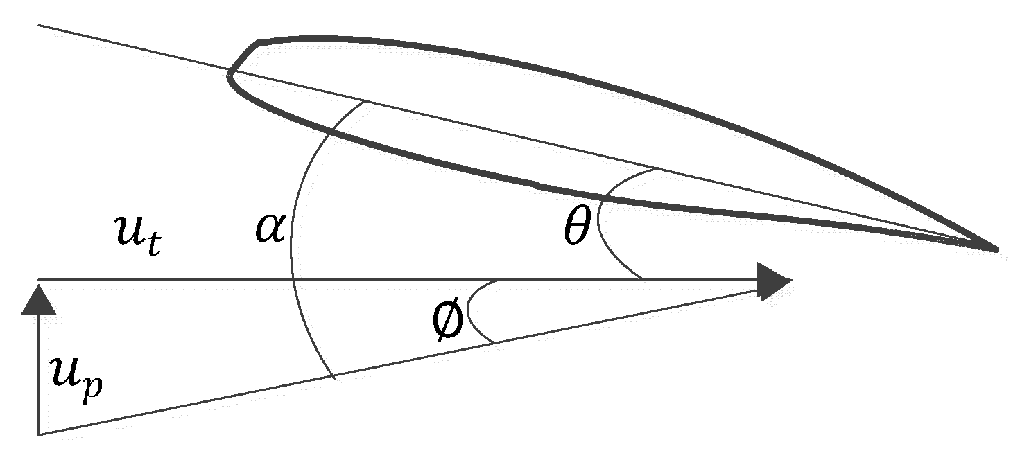
2.1. Rotor Blade Airfoil Aerodynamics
This paper ignores the impact of IBC on original trimming of the helicopter. The individual pitch control superimposes the higher-order harmonic pitch on the basis of the rotor collective pitch control and cyclic pitch control. When a helicopter is flying forward steadily, the angle of attack (AoA) of the rotor blade airfoil is determined by the manipulated variable, the blade twist, the flapping adjustment coefficient and the higher-order harmonic pitch, shown as Equation (1).
where is the pitch angle of the blade. is relative radius of blade section position. and represent the amplitudes of the 2nd and 3rd harmonic. are the phases of the 2nd and 3rd harmonic.
The flow angle of the blade airfoil depends on the relative air flow velocity and direction, as shown in Figure 4.
Figure 4.
The flow angle of the blade airfoil.
Parameters shown in the figure can be obtained from flowing formulas.
where is the angle of the wind speed and is the azimuth of the blade. and are the vertical and lateral components of wind speed.
The flow field of a helicopter rotor is very complex. The method, proposed by Glauert, was used to calculate the inflow air velocity in the hub plane []. The induced velocity is expressed as a superposition of the uniform term and the periodic variation of the radius along the radial direction, shown as Equation (5).
In the formula, the inducing speed is the non-uniform coefficient which can be calculated from uniform inflow model (—induced velocity at the rotor disc center, calculated by the momentum theory). is the uneven coefficient, which is different in various theories. This article is based on the recommended values of Coleman, Feingol and Stempin, as shown in Equation (6).
The aerodynamic model proposed by Leishman and Beddoes is used to calculate the airfoil aerodynamics []. This model takes into account the delay effect of aerodynamic load response caused by dynamic stalls, and it also takes into account the different conditions of the aerodynamic environment (attachment flow, trailing edge separation and leading-edge separation), which accounts for the compressibility of the air flow, the lift loss caused by separation of the airfoil trailing edge and the leading edge.
2.2. Response Solution
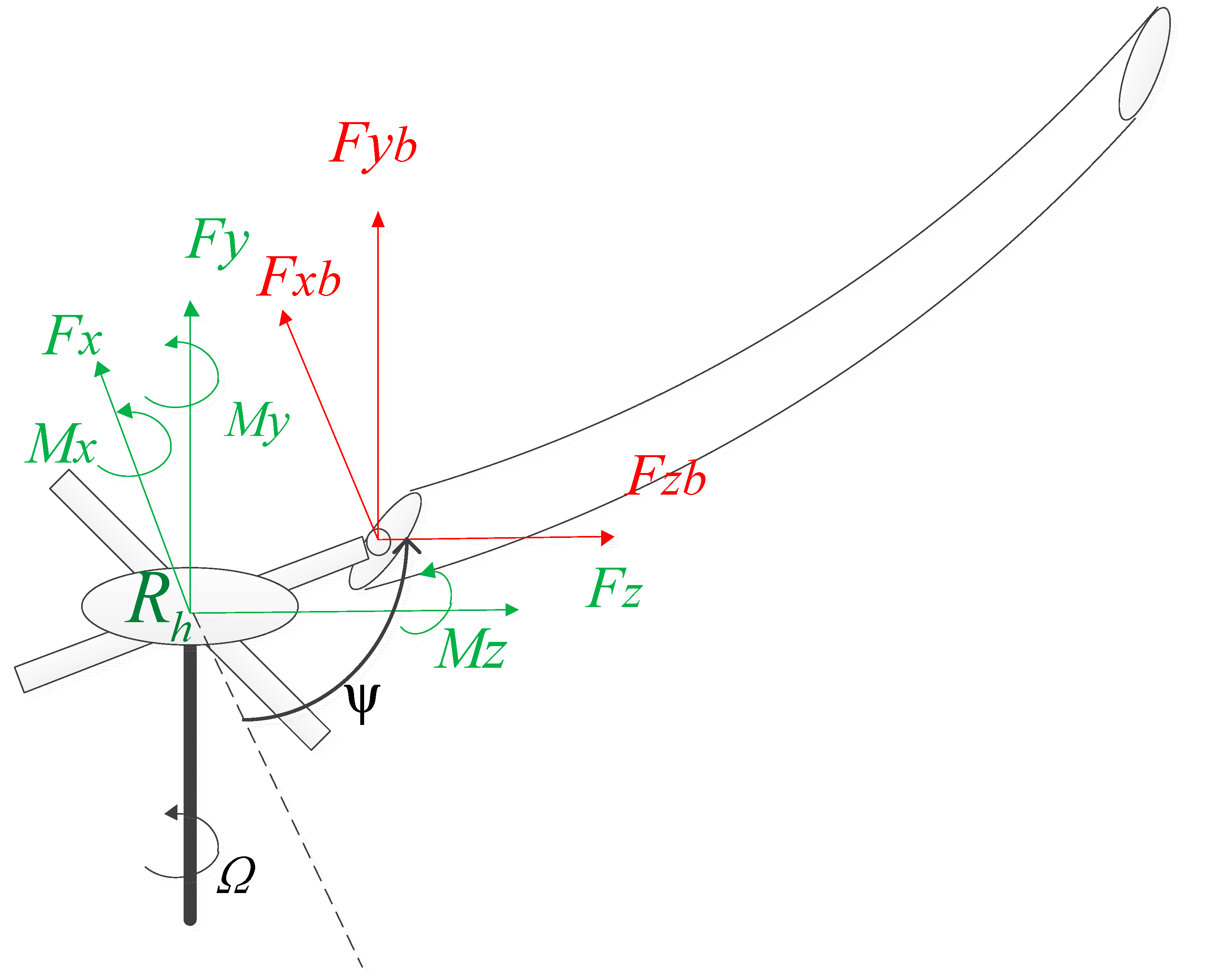
The rotor blade is analyzed as an elastic beam [,,]. Hamilton’s variational principle is used to derive the system equations of motion, which can be expressed as
where , , and are the virtual variation of strain energy, kinetic energy and the virtual work done by external forces. The variations can be written as
where is axial strain, and and are engineering shear strains. is rotating deformed blade coordinate system. , , and are the distributed airloads in the x, y, z directions, respectively, and is the aerodynamic pitching moment about the undeformed elastic axis.
For the i-th blade, the virtual energy expression in Equation (7) is written in the discretized form such that
Using the notation
The blade is discretized into a number of beam elements. There are six degrees of freedom at each element boundary node. The elemental nodal displacement vector is defined as
Using appropriate shape functions, the elemental variation in energy can be written in the following matrix form as
where, and are (blade) elemental mass, damping, stiffness and load matrices.
By assembling elemental matrices, the total energy can be expressed as
The above formula can be transformed into the following finite element equation of the motion of the blade.
The modal superposition method is used in the case study to calculate the blade response. The modal superposition method refers to expressing the response of the structural system as a linear superposition of the natural modes of each order according to the inherent characteristics of the structural system [,,], as shown in Equation (17).
where is modal matrix of the blade. was derived from the in Equation (16) by using the EIG function in matlab.
The blade system has a large degree of freedom, and it is impossible to superimpose the modes of all orders. It is necessary to perform modal truncation, and so a certain degree of calculation accuracy will be lost. Since the rotor vibration loads are mainly concentrated in the low frequency part and magnitudes of high frequency components are low, the high-order modal response amplitudes are small, and the modal truncation has little effect on the response results, so the method can satisfy the calculation needs.
2.3. Hub Loads
The hub loads can be obtained by the superposition of the loads at the root of each blade, as shown in Equation (18). Figure 5 shows the positional relationship of each force direction.
where e is flap and lag hinge offset of the blade. The loads of the blade are obtained by integrating the loads of each blade profile in the spanwise direction, as shown in Equation (19).
Figure 5.
The relationship of each force direction.
The loads can be written as Equation (20).
where is the aerodynamic load which can be written as Equation (21), and is inertial loads, which refers to [].
where and are the drag and lift of blade profile, and is the angular displacement of the profile.
3. Case Study
The model established in Section 1 can be used to calculate the hub loads of traditional single-rotor helicopters and is not applicable to new configuration helicopters such as coaxial helicopters. A helicopter with a 3-bladed main rotor is adopted in the case study as an example []. The rotor parameters of the helicopter are shown in Table 1 and blade properties of each section are listed in Table 2, in which r means radial station, EIf is flap stiffness, EIl is lag stiffness, GJ is torsional stiffness, M is blade sectional mass and YG is chordwise blade c.g. location. In the studied case, the influence of different amplitudes and phases of different harmonic components of IBC and their combinations was analyzed.
Table 1.
Parameters of the main rotor.
Table 2.
Properties of the blade section.
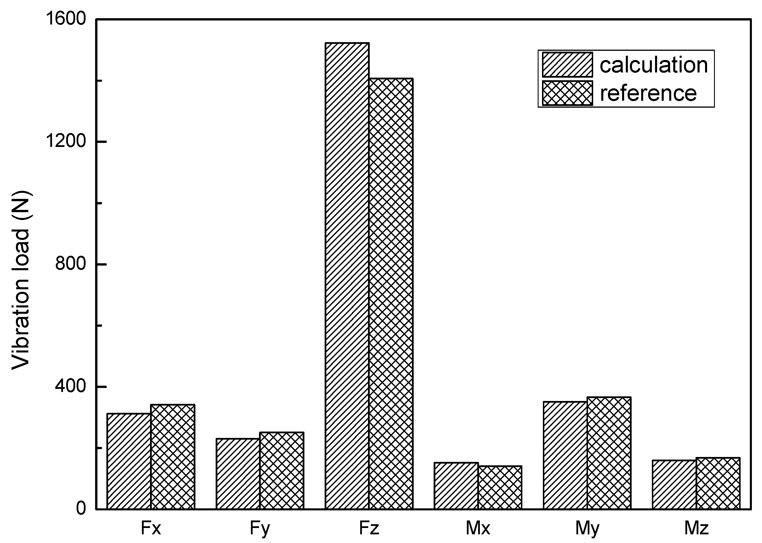
3.1. Model Validation
According to the above rotor parameters and sectional blade properties, the modal frequency of the blade during rotating state was obtained and compared with the calculation results in []. The results are shown in Table 3.
Table 3.
The mode frequencies.
Then, the parameters were substituted into the model established in Section 1 to obtain the hub loads. The result is subjected to FFT transformation, and the 3/rev vibration loads obtained is compared with the results calculated by Heffernan using uniform inflow when the helicopter flew at a speed of 56.4 m/s [,]. The comparison result is shown in Figure 6. The calculation results differ by about 10%. The calculation model is credible.
Figure 6.
A comparison of calculated vibration load values with reference values.
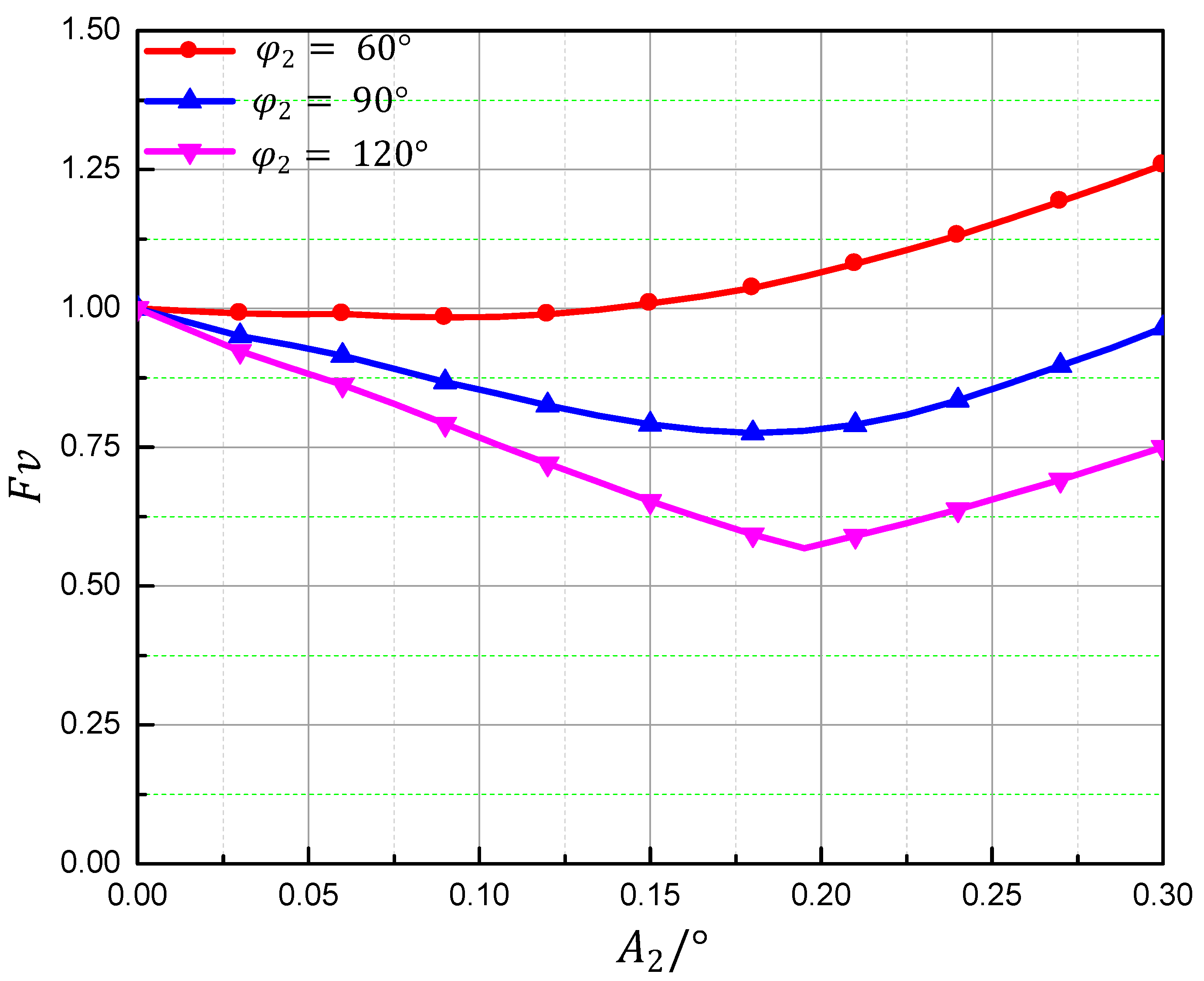
3.2. Influence of Harmonic Phases and Amplitudes
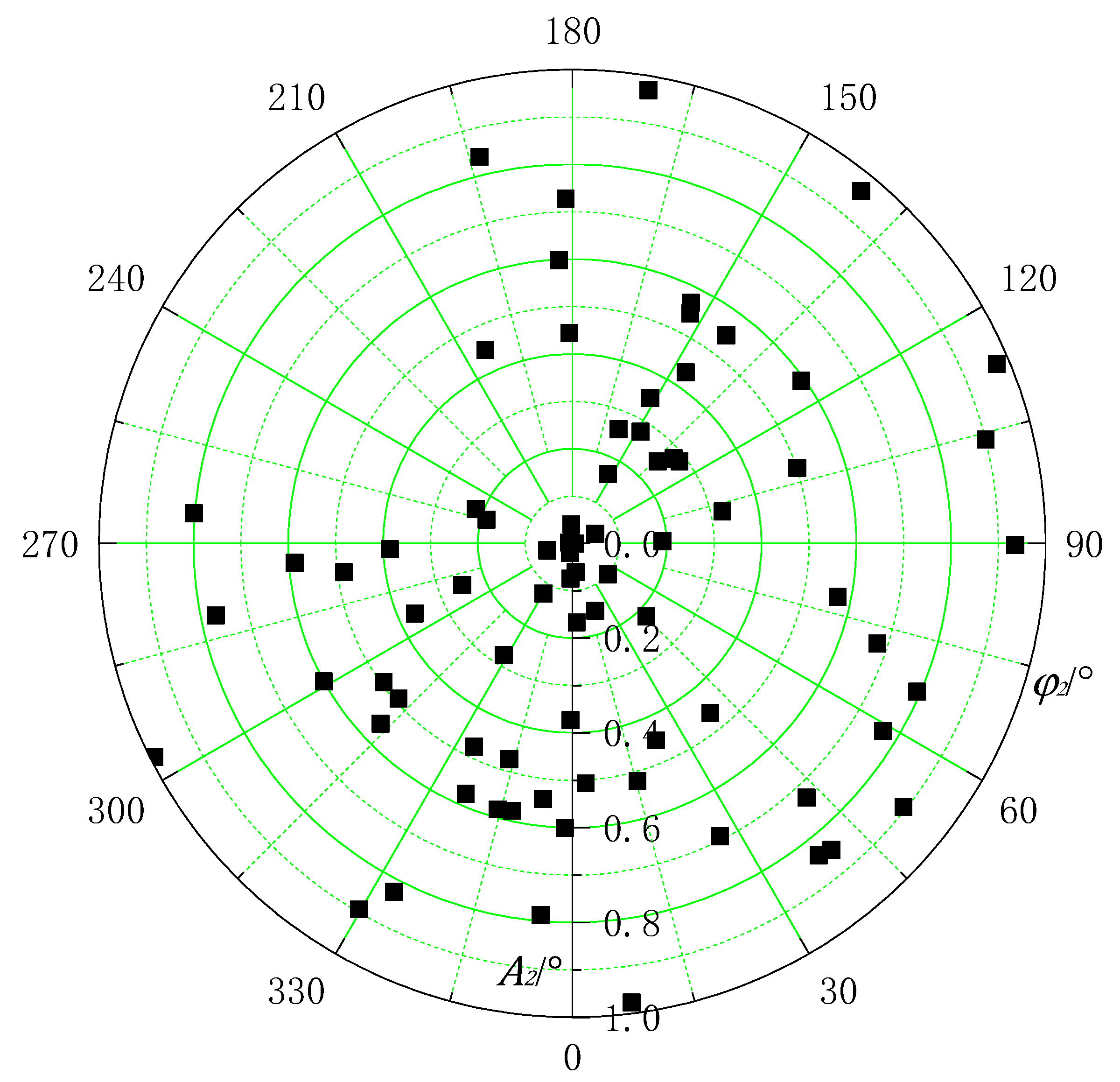
In order to analyze the influence of amplitudes and phases of high-order harmonics on the vibration loads of the hub, the vibration load parameter is defined. is given by
Fvh0 is used to represent the baseline vibration loads without IBC. Fv, which is the ratio of Fvb to Fvb0, can represent the impact of IBC on the vibration loads of the hub. Fv is given by
If Fv is less than 1, it means the IBC algorithm with the selected amplitudes and phases are beneficial to vibration loads reduction; otherwise, vibration loads will become greater than those of the baseline model and IBC algorithm fails, which is adverse.
At first, some specific amplitudes of the harmonic were selected and kept unchanged in the analysis. The phases were changed from 0° to 360° with 30° spacing. Results for when the helicopter was flying under the speed of μ = 0.26 (advance ratio) are shown in Figure 7.
Figure 7.
The influence of the phase of second order harmonicon vibration loads.
It can be seen in Figure 7 that the vibration load ratio changed significantly with the variety of phases of second order harmonics. They all decreased firstly, then increased as the phases increased. The vibration loads became minimum when phase angles of the second order harmonics reached about 150°. It can be seen from Figure 7 that under the action of the second order harmonic with an amplitude of 0.3° and a phase of 150°, the vibration load was less than 50% of the original.
Similarly, some specific phases of the harmonics were selected and kept unchanged in the analysis in order to investigate the impact of harmonic magnitudes on vibration loads reduction under IBC.
The phases investigated in the analysis changed from 0° to 0.3°. When the helicopter was flying at the advance ratio μ = 0.26, the vibration loads were calculated, the results of which are shown in Figure 8.
Figure 8.
The influence of amplitudes of second order harmonics on vibration loads.
It can be seen in the figure that the vibration loads decrease first and then increase as the amplitudes of the second and third harmonics increase. Also, the figures show that the minimum vibration loads with IBC vary with both the amplitudes and phases of the harmonics applied.
3.3. Optimal States
Due to the complexity of the calculation of the helicopter hub loads, it is difficult to directly obtain the relationship between the vibration loads and the amplitudes and phases of each harmonic, so it is impossible to directly obtain the optimal parameters. So, the genetic algorithm is used to find the harmonic state when the vibration load is minimal [,]. The calculation process is shown in Figure 9.
Figure 9.
The process flow of a genetic algorithm.
At first, each individual is encoded as a 22-bit string. The first 10 bits represent the amplitude of the high-order harmonic, and the last 12 bits represent the phase of the high-order harmonic. The variation range of amplitude is 0–1°. The phase variation range is 0–360°. The amplitude calculation accuracy is , and the phase calculation accuracy is .
80 randomly generated individuals form the initial population, which is shown in Figure 10. Then, the fitness evaluation of each individual is evaluated. The fitness is reciprocal of Fv; that is, the smaller the vibration, the higher the fitness. Then, the top 50% in fitness are selected to generate offspring for the next generation by crossing their string. Some individuals also have mutations. After that, a new population is formed which will be used in the next round of calculation. The GA parameters used in the calculation are listed in Table 4.
Figure 10.
The initial population.
Table 4.
Parameters of the genetic algorithm.
The population after 100 generations of reproduction is shown in Figure 11. Figure 12 shows the variation of the optimal individuals in each generation. The trend chart of Fv under each generation of optimal individuals is shown in Figure 13.
Figure 11.
The final population.
Figure 12.
Variations of the optimal individual.
Figure 13.
The trend chart of Fv under each generation of optimal individuals.
It can be seen in Figure 10 and Figure 11 that the initial population is randomly distributed, the distribution is relatively scattered and the final population distribution is concentrated. The population appears to be small in Figure 10 because the optimal individual data overlap.
Figure 12 shows that after 50 generations of evolution, the optimal individual in the population is close to the final optimal value, indicating that the genetic algorithm can quickly solve the optimal state in vibration control by IBC. As can be seen in Figure 13, 60% of the vibration reduction effect can be achieved after 30 evolutions, and the final vibration reduction effect can reach more than 65%.
The initial population is widely distributed, and the probability of new optimal individuals generated by crossover is high. Therefore, in the first 10 iterations, the optimal individual changes greatly, and the vibration load decreases rapidly. At the 50th generation, with the generation of mutation, the first 10 bits of new individuals changed greatly, which was manifested as a sudden change in the amplitude of the harmonic. Because of this, the vibration load decreased rapidly once again. After that, the optimal individual did not change much, and had little effect on the vibration load of the hub. After 10 iterations of data updates, the population tended to be stable, although the crossover probability was relatively large, and it was difficult to generate new optimal individuals. Therefore, the changes in amplitude and phase were very small or even unchanged. Correspondingly, the vibration load of the hub changed little. The phase and amplitude of the optimal individual in the population changed greatly at the 30th and 50th iteration, but the vibration load of the hub decreased more at the 50th iteration compared with that at the 30th iteration, indicating that the parameter sensitivity of amplitude was greater than the phase during optimization, so the appropriate surface height difference (i.e., the amplitude of the second order harmonic) is particularly important in the structural design of the actuator.
4. Conclusions
This article investigated the influence of IBC on helicopter hub vibration load reduction. Not all states of amplitudes and phases could be used for reducing hub vibration loads. The vibration loads could become even greater than those of a baseline system without IBC for some control laws.
The parameters of the blade were simplified compared with reference. The blade segments with similar parameters were merged together, which reduced the blade segments and effectively shortened the calculation times during a large number of repeated iterative calculations. By comparing the results of the characteristics of the blade in the original text, it was found that the errors were very small, indicating that reducing the number of segments of the blade was accurate.
The GA can quickly and effectively realize the solution of the optimal state. By choosing appropriate parameters of amplitude and the phase of the second harmonic, calculated by GA, the vibration load of the hub could be reduced by 65%.
For future work, the accuracy of the proposed method should be verified via experimentation. It is necessary to analyze the influence of other harmonics—such as the third harmonic—on the vibration load of the hub.
Author Contributions
Conceptualization, H.W.; methodology, X.N.; software and validation, Y.G.; investigation and writing—original draft preparation, R.Y. R.Y. and Y.G. contributed equally to this paper. All authors have read and agreed to the published version of the manuscript.
Funding
This research was funded by the Fundamental Research Funds for the Central Universities, grant number NS2015013 and the Priority Academic Program Development of Jiangsu Higher Education Institutions.
Institutional Review Board Statement
Not applicable.
Informed Consent Statement
Not applicable.
Data Availability Statement
Not applicable.
Conflicts of Interest
The authors declare no conflict of interest.
References
- Ellis, C.W.; Jones, R. Application of an absorber to reduce helicopter vibration levels. J. Am. Helicopter Soc. 1963, 8, 30–42. [Google Scholar] [CrossRef]
- Lu, Y. Research on Electronically Controlled Rotor System. Ph.D. Thesis, Nanjing University of Aeronautics and Astronautics, Nanjing, China, 2004. [Google Scholar]
- Cesnik, C.E.S.; Shin, S.J.; Wilbur, M.L. Dynamic response of active twist rotor blades. Smart Mater. Struct. 2001, 10, 62–76. [Google Scholar] [CrossRef]
- Welsh, W.; Fredrickson, C.; Rauch, C.; Lyndon, I. Flight test of an active vibration control system on theUH-60 black hawk helicopter. In Proceedings of the 51th Annual Forum of the American Helicopter Society, Fort Worth, TX, USA, 8–11 May1995. [Google Scholar]
- Miao, W.; Kottapalli, S.B.R.; Frye, H.M. Flight demonstration of higher harmonic control (HHC) on S-76. In Proceedings of the 39th Annual Forum of the American Helicopter Society, Washington, DC, USA, 9–11 May 1983. [Google Scholar]
- Ham, N.D. A simple system for helicopter individual-blade control and its application to gust alleviation. In Proceedings of the 16th European Rotorcraft Forum, Bristol, UK, 18–21 September 1990. [Google Scholar]
- Ham, N.D. Helicopter individual-blade-control: Promising technology for the future helicopter. In Proceedings of the 21th European Rotorcraft Forum, Saint Petersburg, Russia, 30 August–1 September 1995. [Google Scholar]
- Jacklin, S.A.; Haber, A.; Simone, G.; De Norman, T.R.; Kitaplioglu, C.; Shinoda, P. Full-scale wind tunnel test of an individual blade control system for a UH-60 helicopter. In Proceedings of the 58th Annual Forumof American Helicopter Society, Montréal, QC, Canada, 11–13 June 2002. [Google Scholar]
- Fuerst, D.; Hausberg, A. Experimental verification of an Electro-Mechanical-Actuatorfor a swashplateless primary and individual helicopter blade control system. In Proceedings of the 64th Annual Forum of American Helicopter Society, Montréal, QC, Canada, 29 April–1 May 2008. [Google Scholar]
- Kuefmann, P.; Bartels, R.; van der Wall, B.G. The first wind-tunnel test of the DLR’s multiple swashplate system: Test procedure and preliminary results. In Proceedings of the 72nd Annual Forum of the American Helicopter Society, West Palm Beach, FL, USA, 17–19 May 2016. [Google Scholar]
- Ma, Y.J.; Yun, W.X. Research progress of genetic algorithm. Appl. Res. Comput. 2012, 29, 1201–1210. [Google Scholar]
- Ullah, Z.; khan, M.; Raza Naqvi, S.; Farooq, W.; Yang, H.; Wang, S.; Vo, D.V.N. A comparative study of machine learning methods for bio-oil yield prediction—A genetic algorithm-based features selection. Bioresour. Technol. 2021, 335, 125292. [Google Scholar] [CrossRef] [PubMed]
- Naranjo-Pérez, J.; Jiménez-Manfredi, J.; Jiménez-Alonso, J.; Sáez, A. Motion-based design of passive damping devices to mitigate wind-induced vibrations in stay cables. Vibration 2018, 1, 269–289. [Google Scholar] [CrossRef] [Green Version]
- Zhang, Y.; He, L.; Yang, J.; Zhu, G.; Jia, X.; Yan, W. Multi-objective optimization design of a novel integral squeeze film bearing damper. Machines 2021, 9, 206. [Google Scholar] [CrossRef]
- Liu, Q.; Zha, Y.; Liu, T.; Lu, C. Research on adaptive control of air-borne bolting rigs based on genetic algorithm optimization. Machines 2021, 9, 240. [Google Scholar] [CrossRef]
- Omar, H.M. Optimal geno-fuzzy lateral control of powered parachute flying vehicles. Aerospace 2021, 8, 400. [Google Scholar] [CrossRef]
- Johnson, W. Helicopter Theory; Dover Publications: New York, NY, USA, 1980; p. 139. [Google Scholar]
- Leishman, J.G.; Beddoes, T.S. A semi-empirical model for dynamic stall. In Proceedings of the 42nd Annual Forum of American Helicopter Society, Washington, DC, USA, 2–4 June 1986. [Google Scholar]
- Bir, G.; Chopra, I. University of Maryland Advanced Rotorcraft Code Theory Manual; Center for Rotorcraft Education and Research University of Maryland: College Park, MD, USA, 1994. [Google Scholar]
- Zhou, J. Simulation and Analysis of Smart Rotor with Dual Trailing-Edge Flaps. Master’s Thesis, Nanjing University of Aeronautics and Astronautics, Nanjing, China, 2015. [Google Scholar]
- Zhou, H. Research on Vibration Suppression and Realization of Smart Rotor based on Dual Trailing-Edge Flaps. Master’s Thesis, Nanjing University of Aeronautics and Astronautics, Nanjing, China, 2020. [Google Scholar]
- Hodges, D.; Dowell, H. Nonlinear Equations of Motion for the Elastic Bending and Torsion of Twisted Nonuniform Rotor Blades; NASA: Washington, DC, USA, 1974. [Google Scholar]
- Huiping, S. An improved mode superposition method for linear damped systems. Commun. Appl. Numer. Methods 1991, 7, 579–580. [Google Scholar] [CrossRef]
- John, M.; Newman, S. Basic Helicopter Aerodynamics, 4th ed.; Wiley-Blackwell: Hoboken, NJ, USA, 2011. [Google Scholar]
- Heffernan, R.; Gaubert, M. Structural and Aerodynamic Loads and Performance Measurements of SA349/2 Helicopter with an Advanced Geometry Rotor; NASA: Washington, DC, USA, 1986; pp. 15–103. [Google Scholar]
- Heffernan, R.M.; Yamauchi, G.K.; Gaubert, M.; Johnson, W. Hub Loads Analysis of the SA349/2 Helicopter; NASA: Washington, DC, USA, 1988. [Google Scholar]
- Liu, Q.; Hu, G.; Lei, W. Parameter identification and application of rotor airfoil dynamic stall model. J. Nav. Aeronaut. Astronaut. Univ. 2015, 30, 129–133. [Google Scholar]
- Chen, B.; Liu, W. SAC model based improved genetic algorithm for solving TSP. J. Front. Comput. Sci. Technol. 2021, 15, 1680–1693. [Google Scholar]
- Pan, J.; Qian, Q.; Fu, Y. Multi-population genetic algorithm based on optimal weight dynamic control learning mechanism. J. Front. Comput. Sci. Technol. 2021, 15, 2421–2437. [Google Scholar]
Publisher’s Note: MDPI stays neutral with regard to jurisdictional claims in published maps and institutional affiliations. |
© 2022 by the authors. Licensee MDPI, Basel, Switzerland. This article is an open access article distributed under the terms and conditions of the Creative Commons Attribution (CC BY) license (https://creativecommons.org/licenses/by/4.0/).