1. Introduction
The high-speed permanent magnet motor (HSPMM) has the advantages of small volume, high power density [
1], high efficiency and a direct connection with a high-speed load [
2]. It has won more and more favor and gained wider application prospects in the fields of high-speed blowers [
3], compressors [
4], flywheel energy storage [
5] and so on.
Common rotor structures are the interior permanent magnet (IPM) and surface-mounted permanent magnet (SPM). Rotor structural characteristics determine their respective application fields. For high-speed applications, SPM is often used. In IPM, the thickness of the magnetic bridge outside the rotor core is the key parameter to ensure the safe operation and electromagnetic performance of the motor [
6]. The thicker magnetic bridge can ensure the high-speed operation of the rotor, but at the same time, it will also produce obvious magnetic leakage in the magnetic bridge and reduce the output torque of the motor. In contrast, the SPM, with the protection of a high-stress alloy or carbon fiber sleeve, is more suitable for high-speed operation [
7].
Table 1 illustrates the mechanical, electrical and thermal conductivity of several rotor-protection materials at room temperature [
8]. It can be seen that the high electrical conductivity of the metallic sleeve often produces obvious eddy current loss, and because of this, eddy current loss in PM will be restrained. When composite sleeve is made of carbon fiber or glass fiber, the eddy current loss in the sleeve is very small, but the eddy current loss of the PM is obvious. For eddy current losses on rotor components, the circumferential slotting in [
9] can effectively suppress the eddy current loss in the metal sleeve, and the axial segmentation of PM can reduce the loss in it. In addition, from the perspective of heat dissipation, the thermal conductivity of a metal sleeve is better than that of carbon fiber [
10]. Therefore, when the internal loss of PM is large, the use of a carbon fiber sleeve is not conducive to the heat dissipation of the rotor. At this time, special attention should be paid to the calibration of the rise in motor temperature.
When analyzing the rotor stress, it is necessary to fully consider the influence of the material characteristics of each component [
11]. For the commonly used sintered permanent magnet, the compressive stress it can bear is much greater than the tensile stress [
12]. Using this feature, the shrink fit is usually used to fix and protect the permanent magnet in the rotor design, including the low-temperature treatment of the permanent magnet and the rotor yoke or the hot sleeve process of the alloy sleeve [
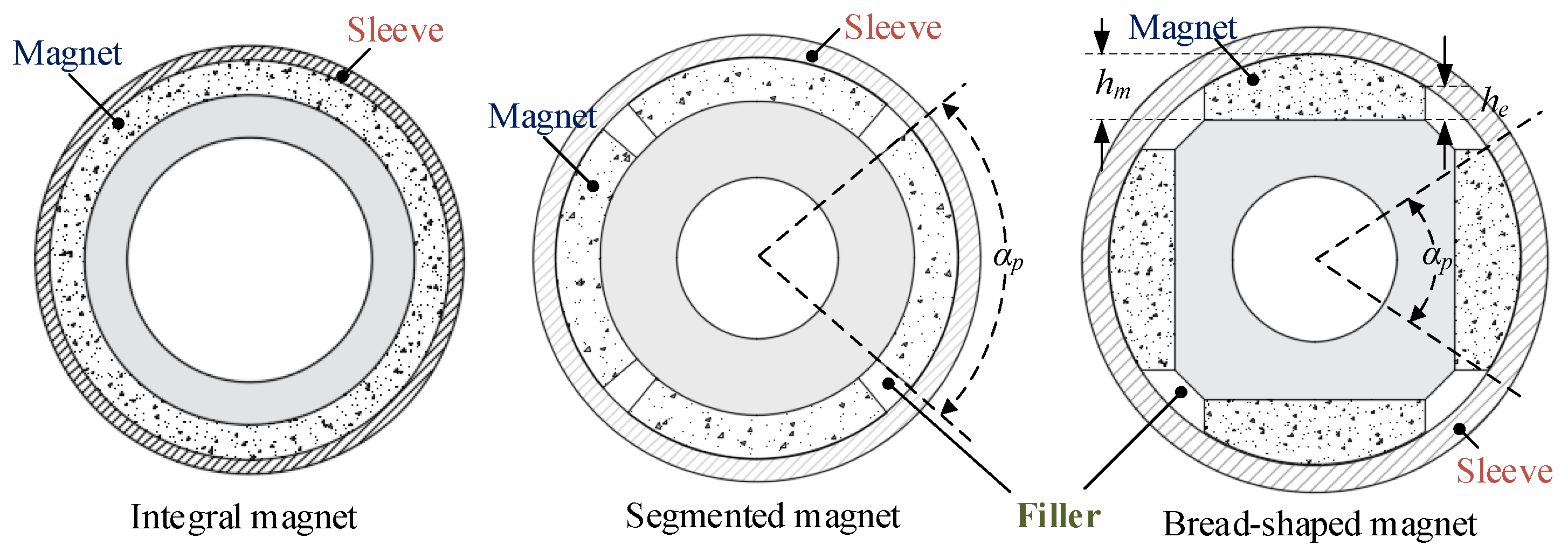
13]. In addition, the structure of the magnet will also affect the rotor stress. Generally, the SPM adopts magnet structures such as the integral magnet, segmented magnet and bread-shaped magnet. Among them, the integral magnet with a pole arc coefficient of 1 is mostly used in motors with a pole pair of 1. The structure of the segmented magnet and bread-shaped magnet needs to adjust the pole arc coefficient according to the electromagnetic performance, so the material of fillers will affect rotor stress.
In addition, due to the high temperature during the operation of the motor, the thermal stress caused by the rotor temperature and the different thermal expansion coefficients of components needs to be fully considered in the stress analysis. At present, in the existing literature, the rotor is usually comprehensively analyzed under different working conditions such as a low-temperature static state, high-temperature static state, low-temperature high-speed state and high-temperature high-speed state, and the stress distribution in the sleeve and magnet is discussed and judged according to their respective judgment standards [
8]. For example, in [
14], three common sleeve materials are analyzed on the premise of considering rotor strength and electromagnetic design. During the analysis, constant temperatures of 20 °C, 80 °C and 150 °C were selected. This setting helped the author to quickly analyze the strength distribution characteristics of rotors made of different materials under multiple working conditions, and lay the foundation for the subsequent proposal of a multi-layer sleeve structure. However, the forced air cooling method adopted by the motor ignores the axial temperature gradient on the rotor. Similarly, in the design process of a 1.12 MW 12 kr/min high-speed permanent magnet motor in [
15], the overall temperature of the sleeve was set at 150 °C and the rotating speed was increased by 20% to ensure a certain design margin.
However, this method of setting the same temperature state for the whole rotor has some limitations. Differences in the position of rotor components often result in temperature differences. The influence of the temperature difference and temperature gradient of rotor components on rotor stress is considered in [
16]. The research shows that the influence of the temperature difference between the sleeve and the magnet on the rotor stress can be ignored, but the influence of the temperature gradient between the magnets on the rotor stress must be seriously considered. In addition, the rotor stress obtained by the isothermal model is bigger than that obtained by the coupled thermal-stress model. Therefore, in the stress analysis, it is necessary to establish a 3D temperature stress coupling model in order to obtain more accurate calculation results and a design of the best size.
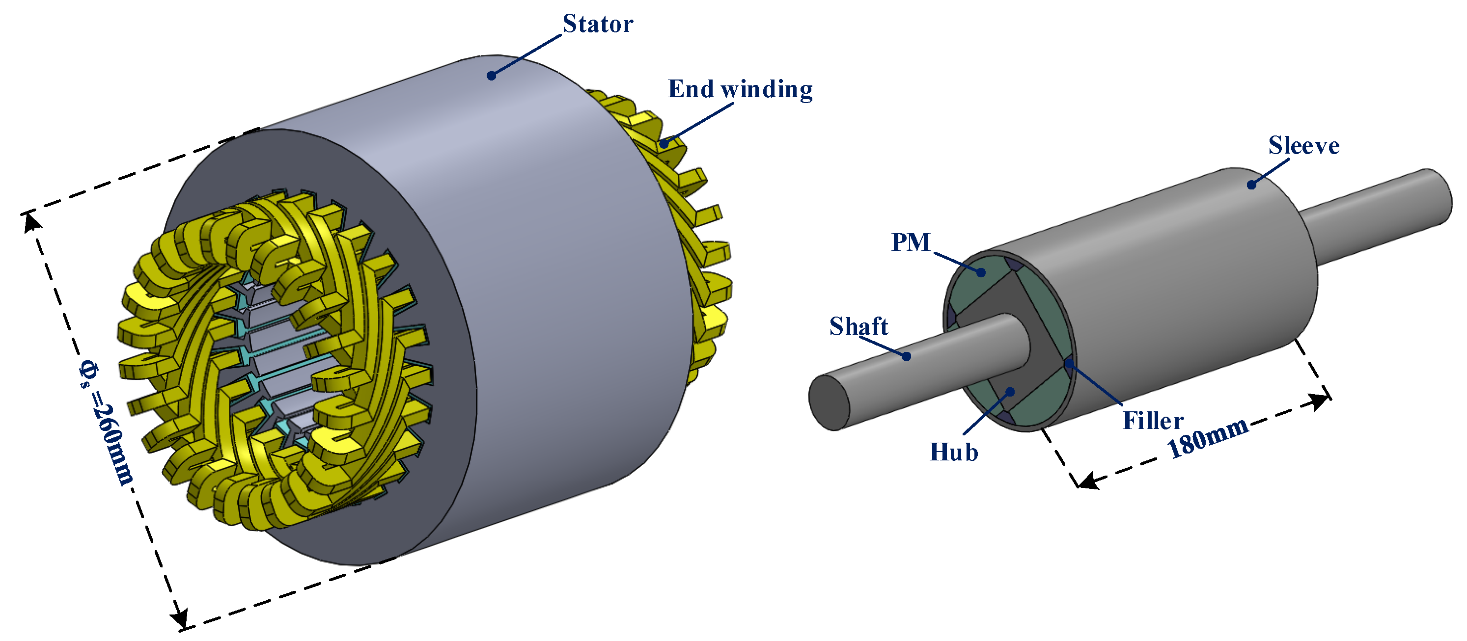
For the axial ventilation cooling mode of one side inlet and one side outlet, a more obvious temperature gradient is generated on the rotor. Therefore, it is necessary to fully consider the influence of the axial temperature gradient caused by the cooling mode in rotor stress analysis. This paper takes a 200 kw 20,000 r/min HSPMM magnetic bearing as the research object, and conducts a detailed study on rotor stress. Firstly, the stress distribution characteristics of different types of SPM and the influence of filler materials on the stress distribution are compared and analyzed. Secondly, the thickness of the sleeve and shrink fit are determined by calculation results. In addition, the influence of rotor temperature gradient on stress under axial ventilation cooling is fully considered by computational fluid dynamics. Finally, an experiment is carried out to verify the correctness of the theoretical analysis.
3. Influence Factors of Rotor Stress
3.1. The Structure of the Magnet
At present, the SPM has three main structures: an integral magnet, a segmented magnet with an arc coefficient less than 1 and a bread-shaped magnet, as shown in
Figure 2. For the integral magnet, because of the concentric circle structure of regular shape, it is easier to solve the stress result analytically by using the cylinder wall model when using an isotropic sleeve. If the mechanical properties (density, thermal expansion coefficient, Poisson’s ratio and elastic modulus) of the filler are close to the parameters of the magnet, it can also be solved by the analytical method when the structure of the integral magnet with a pole-arc coefficient less than 1 is used. However, the bread-shaped magnet has an irregular magnet shape, which causes a large calculation error in the analytical model.
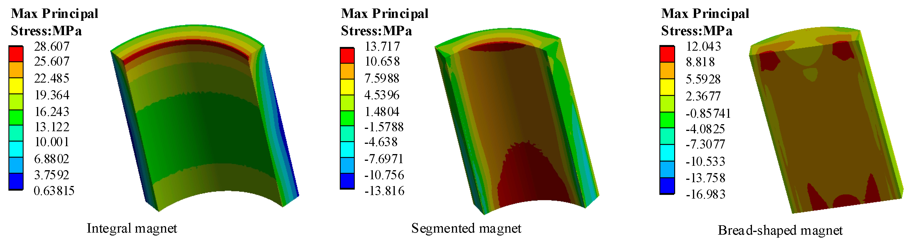
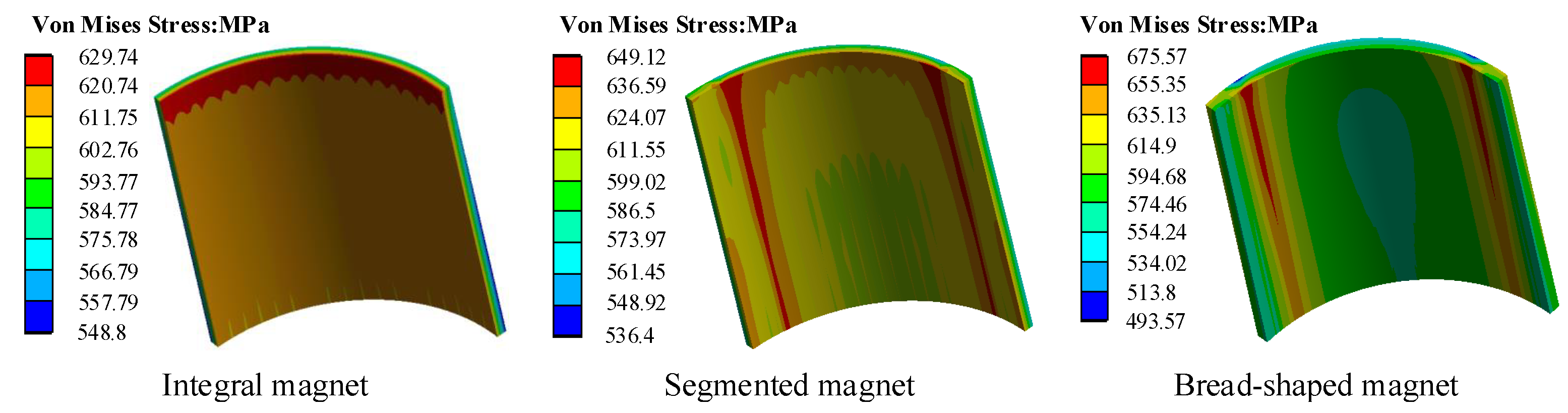
In order to understand the stress distribution of different rotor structures more accurately and clearly, the 3D FEA is adopted by Ansys Workbench. The analysis results of different SPM structures at 24,000 r/min (1.2 ∗ Rated speed) and 80 °C are shown in
Figure 3 and
Figure 4. Among the three rotor structures, the sleeve material is Inconel 718, and the thickness is 3 mm; the magnets are made of N45UH; and the material of the shaft is S45C. In addition, the rotor diameter and shrink fit are also consistent. Considering the symmetry of the rotor components, in order to reduce the calculation amount and shorten the calculation time, 1/4 is taken in the circumferential direction; at the same time, due to the influence of magnet structure on rotor strength, as discussed here, a constant temperature condition is set. Therefore, the axial half can be further selected for analysis.
It can be seen that the Von Mises stress of the integral magnet structure is the lowest (629 MPa), while the material properties of the segmented and bread-shaped structures with fillers are different from those of magnets, resulting in a steep increase in stress at the contact position of fillers and PMs. In the bread-shaped magnet, the stress value is larger due to the non-uniformity of its structure along the radius direction.
On the other hand, in the integral magnet structure, the inner diameter of the magnet is subjected to tensile stress of up to 28 MPa when subjected to centrifugal force and thermal stress. Although the shapes of the PM materials in the latter two structures are different, the common feature is that the magnets are separated, so the maximum principal stress of the PMs in the latter two structures is obviously less than the integral magnet structure. Therefore, for the bread-shaped PM selected by the prototype in this paper, the influence of fillers on rotor stress needs to be fully considered.
3.2. Influence of Thermal Expansion Coefficient of Filler on Rotor Strength
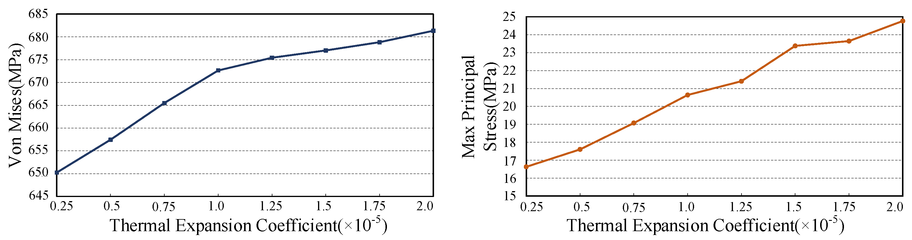
In order to study the influence of the thermal expansion coefficient on rotor stress, a qualitative analysis is carried out. In all calculations of this part, the temperature is set at 80 °C to consider the thermal influence on stress. The thermal expansion coefficient is set to vary between 0.25 × 10/K and 2.0 × 10
−5/K on the premise that the density, elastic modulus and Poisson’s ratio of the filler remain unchanged. The curves of Von Mises stress and maximum principal stress with thermal expansion coefficient are shown in
Figure 5. Obviously, the Von Mises stress and tensile stress increased with the increase in the thermal expansion coefficient. Among them, in the range of 0.25 × 10
−5/K to 1.0 × 10
−5/K, the increase in the Von Mises stress in the sleeve is obvious, but after 1.0 × 10
−5/K, the increase is relatively small.
More accurately, the Von Mises stress in the sleeve with five different fillers materials is calculated. The properties and calculation results of each material are shown in
Table 3, where “PM” refers only to a virtual material with the same physical properties as the magnets used in the prototype, which does not mean that PMs are used as fillers. It can be seen that the maximum Von Mises stress in the sleeve is 643.4 MPa when PM material is used, and the stress is 719.7 MPa for epoxy, which has the largest thermal expansion coefficient.
According to the above analysis, under the high-temperature state of the actual operation of the motor, the larger the thermal expansion coefficient of the filler materials, the larger the deformation gap between them, resulting in an obvious increase in the stress of the sleeve at the joint position of PM and filler. Therefore, the influence of filler materials on rotor stress should be fully considered in rotor design, and materials with properties closer to PM should be selected. In this paper, Inconel 718 is selected as the filler.
3.3. Sleeve Thickness and Shrink Fit
The settings of sleeve thickness and shrink fit are the key factors that determine whether the rotor can run safely. As for the thickness of the sleeve, the thinner thickness can not meet the requirements of the high-speed operation of the motor, and the thicker thickness will increase the eddy current loss on the sleeve. For shrink fit, a small value cannot protect the rotor components, while large shrink fit is not conducive to fabrication and challenges the compressive stress of permanent magnets. In this part, the rotor stress under different sleeve thickness and shrink fit is comprehensively analyzed. The range of sleeve thickness is 2 mm to 4 mm, and the shrink fit is 0.06 mm to 0.18 mm.
The maximum Von Mises stress and maximum principal stress corresponding to different sleeve thickness and shrink fit are shown in
Table 4 and
Table 5. In
Table 4, the Von Mises stress increases with the increase in shrink fit when the sleeve thickness is kept constant. When shrink fit is constant, Von Mises stress decreases with increasing sleeve thickness. For the maximum principal stress, the maximum principal stress has a minimum value in the range of 3 mm to 4 mm, according to
Table 5. In general, when the sleeve thickness is from 3 mm to 4 mm, the shrink fit can be selected as 0.12 mm; when the sleeve thickness is from 2.5 mm to 4 mm, shrink fit can be selected as 0.15 mm. Based on the comprehensive consideration of electromagnetic and rotor stress, the sleeve thickness is selected as 3 mm, and the shrink fit is set as 0.15 mm.
4. Rotor Stress Analysis Considering Cooling Method
4.1. The Characteristic of Cooling
The prototype in this paper is used for the blower drive system of a sewage treatment plant. If housing water cooling is used, it will increase the complexity of the blower system; good sealing and easy-to-obtain cooling water must be guaranteed. Forced air cooling can use part of the air volume generated by the main external cooling fan to cool the motor, which can directly cool the stator core surface, end winding, sleeve and rotating shaft, effectively reducing the temperature rise in the rotor component. In addition, since the air flow of forced air cooling comes from the main impeller connected to the main shaft, there is a self-feedback relationship between the loss and cooling capacity. When the speed rises, the air volume generated by the main impeller increases, so there is more cooling air for the cooling of the motor, allowing it to reach the thermal steady state faster.
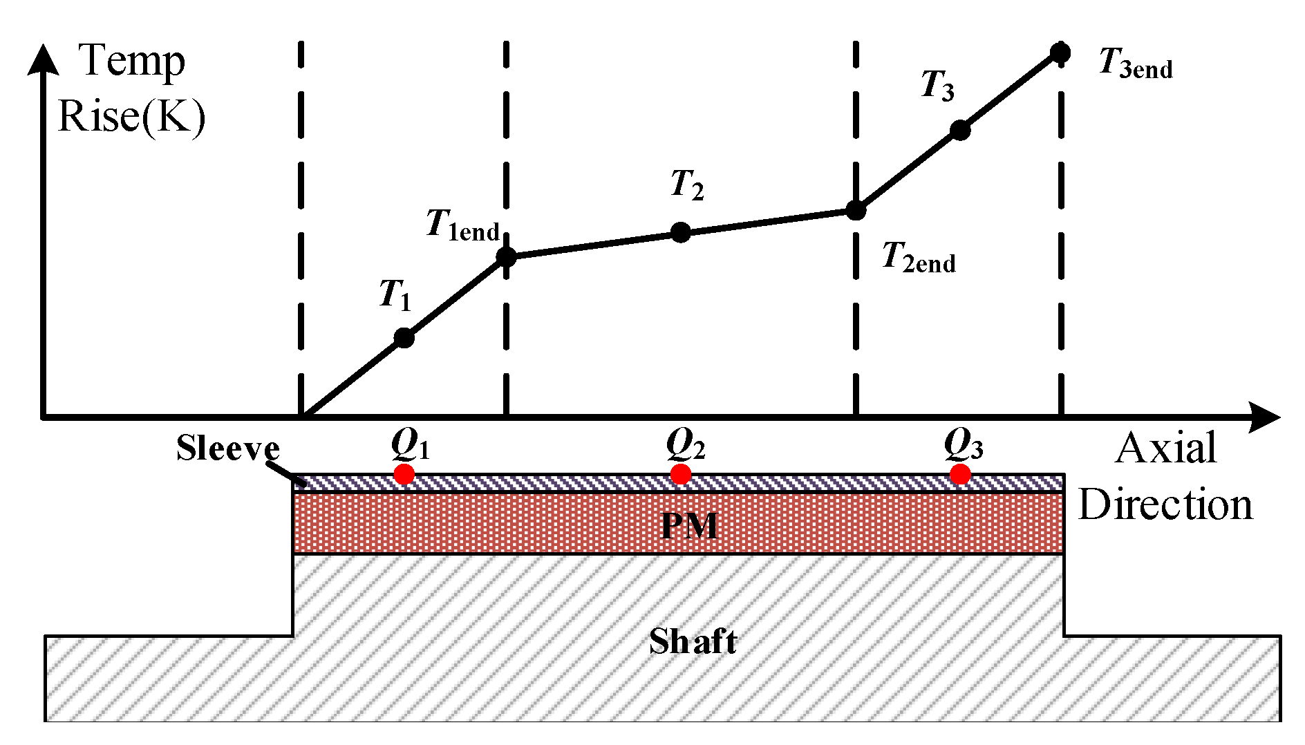
However, this cooling method has two shortcomings. One is the axial temperature gradient. A simple fluid temperature rise model [
8] is shown in
Figure 6. Among them, the cooling fluid with a flow of
Q flows from the left end of the rotor to the right end. In the flow process, the temperature rise of the cooling fluid increases continuously owing to the absorption of heat from the rotor. The whole fluid is modeled with three temperature-rising nodes,
–
, and the heat absorbed by the three nodes is
–
, respectively.
where
and
are the density of the fluid and specific heat. Furthermore,
can be obtained by
the temperature rise of the second node is
similarly
It can be seen that the temperature rise of the cooling fluid node is the temperature rise of the previous node plus the product of the heat inflow from the two nodes and . Because of this, for the axial ventilation cooling where the inlet and outlet are set on both sides of the motor axis, the motor components easily form a certain temperature gradient in the axial direction, and the temperature difference depends highly on the air volume.
4.2. Air Friction Loss
The other disadvantage of forced air cooling is obvious air friction loss. Therefore, it is necessary to analyze air friction losses in the design of a high-speed motor. Air friction losses can be divided into the friction loss generated by the radial surface of the rotor and the surrounding air and the friction loss generated by the axial end of the rotor. The formula for calculating the friction loss
caused by the radial surface of the rotor and the surrounding air is as follows:
where
k is the roughness coefficient of the rotor surface (
for smooth surface, 1–2.5 are common selection ranges);
is the density of the cooling medium (air);
is the angular velocity;
,
,
and
are, respectively, the rotor diameter, axial length of the motor, stator inner diameter and rotor outer diameter; and
is the friction coefficient, which is related to fluid velocity, physical property parameters and characteristic length. The value of
is determined by the range of Reynolds number. When there is no forced axial fluid inside the motor, the value of
is determined by the Reynolds number
:
where
is the length of the air gap, and
is the dynamic viscosity of the cooling medium. The value of
is determined according to the following criteria after calculation.
When there is an axially flowing fluid in the motor, the radial Reynolds number
corresponding to the rotor tangential friction and the axial Reynolds number
corresponding to the fluid axial flow friction should be considered simultaneously:
where
and
can be obtained by
and the axial velocity of the fluid is
where
represents the area where the cooling medium can flow, including the air gap and the area in the slot where no windings are placed.
In addition, the friction loss
on the axial end face of the rotor can be calculated by
where
is the diameter of the shaft and
is the friction coefficient of the axial end face of the rotor. Furthermore, the value of
is determined by the Reynolds number
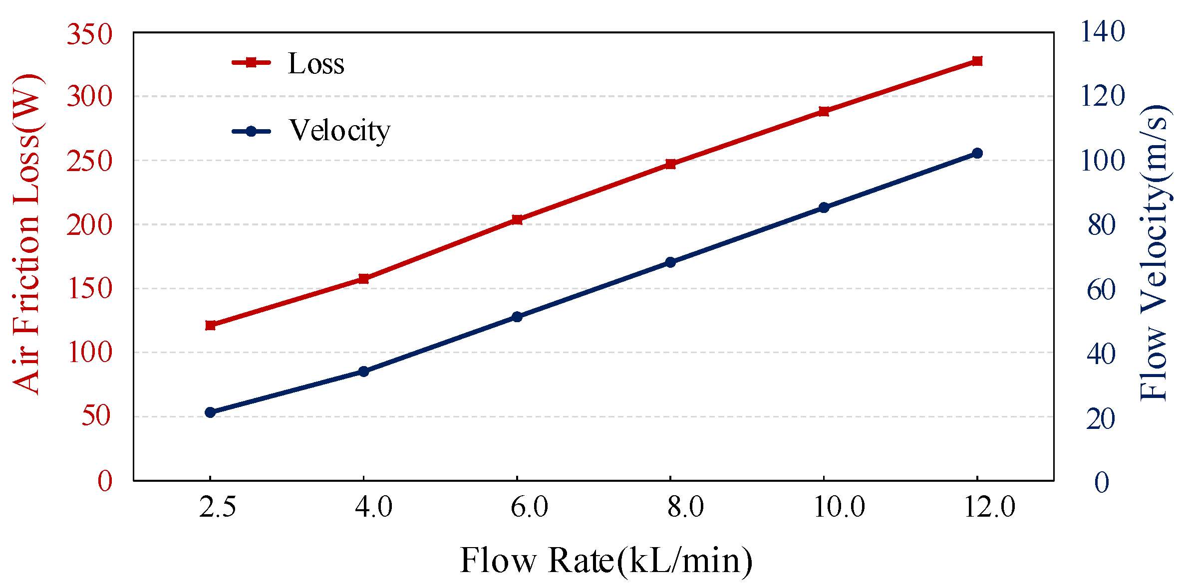
The calculated results are shown in
Figure 7. With the increase in air volume, the axial velocity of air on the rotor surface increases proportionally. At the same time, the wind friction loss also increases. According to the above analysis, the air friction loss is related to the length of the air gap. When designing the motor, the air gap length is set as 6 mm to ensure a larger convective heat transfer surface and reduce the air friction loss.
4.3. Coupled Thermal-Stress Analysis
In order to simultaneously consider the axial temperature gradient caused by cooling mode and the influence of air friction loss on temperature rise, fluent and static stress coupling analysis are used to check the rotor stress. The motor losses are calculated by finite element software JMAG, and the harmonic current obtained from the simulink motor model is used as the excitation of the finite element model to obtain more accurate loss values. The losses under rated operation are shown in
Table 6. Each loss is applied to each part of the motor through the loss density. When the cooling air volume is set to 0.2 m
3/s, the standard k-
model, which is considered to be one of the most robust turbulence models, is used for calculation. At the same time, the viscous heating option is opened to consider the influence of air friction loss on rotor temperature rise.
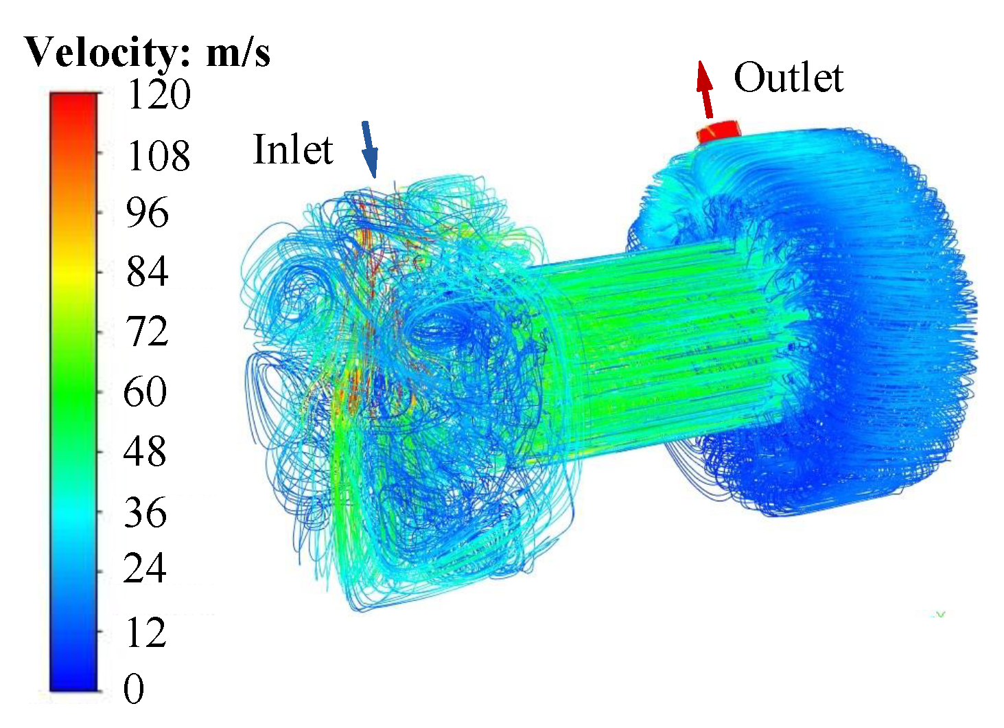
The velocity distribution of the cavity flow field in the motor is shown in
Figure 8. The cooling air enters from the inlet arranged at the housing, blows the end winding, enters the air gap and the slot opening where the winding is not placed, then cools the end winding on the other side, and finally flows out from the outlet. In addition to the inlet and outlet, the air flow rate near the rotor surface is the fastest, at about 85 m/s.
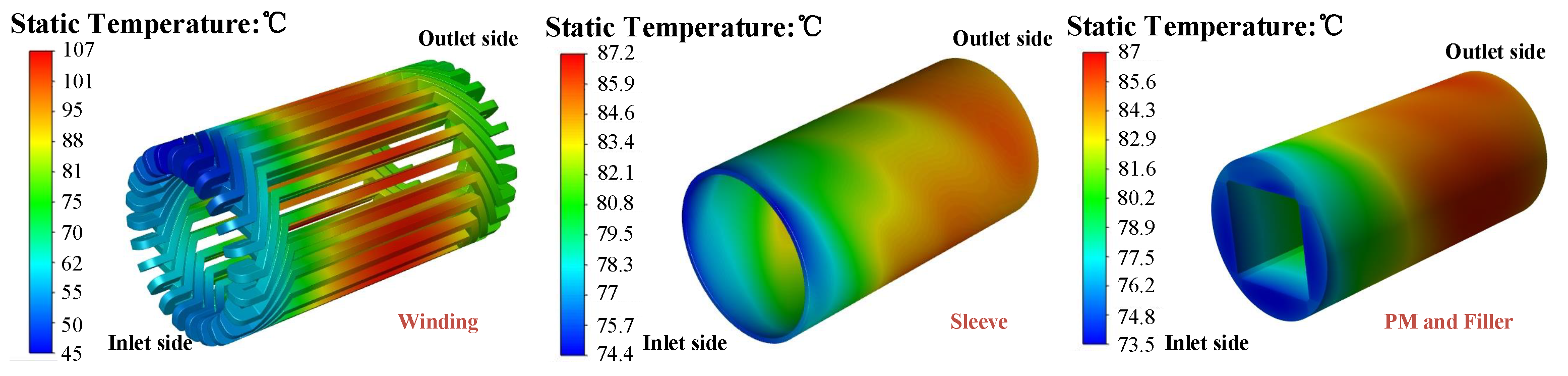
Furthermore, the temperature distribution of the motor windings and rotor components is shown in
Figure 9. As can be seen, for the winding, the inlet of cooling air is set above the left-end winding, and the temperature rise of the end winding in this area is relatively low. Obviously, the overall temperature of the inlet side-end winding is significantly lower than that of the outlet side-end winding. In addition, since there is no active channel cooling on the housing, the temperature of the winding in slots is the highest, with a maximum temperature of about 107 °C.
As can be seen from the temperature distribution of the sleeve, PM and filler, rotor components show an obvious temperature gradient in the axial direction due to ventilation cooling. On the sleeve, the inlet side temperature is only 74.4 °C, while the outlet side temperature is 87.2 °C, and the temperature difference is 12.8 °C. The temperature of PM and filler is 73.5 °C and 87 °C, respectively, with a temperature difference of 13.5 °C. Moreover, due to shrink fit processing between the sleeve and PMs, the contact gap between them is very small, so the temperature of the sleeve is quite close to that of PMs and fillers.
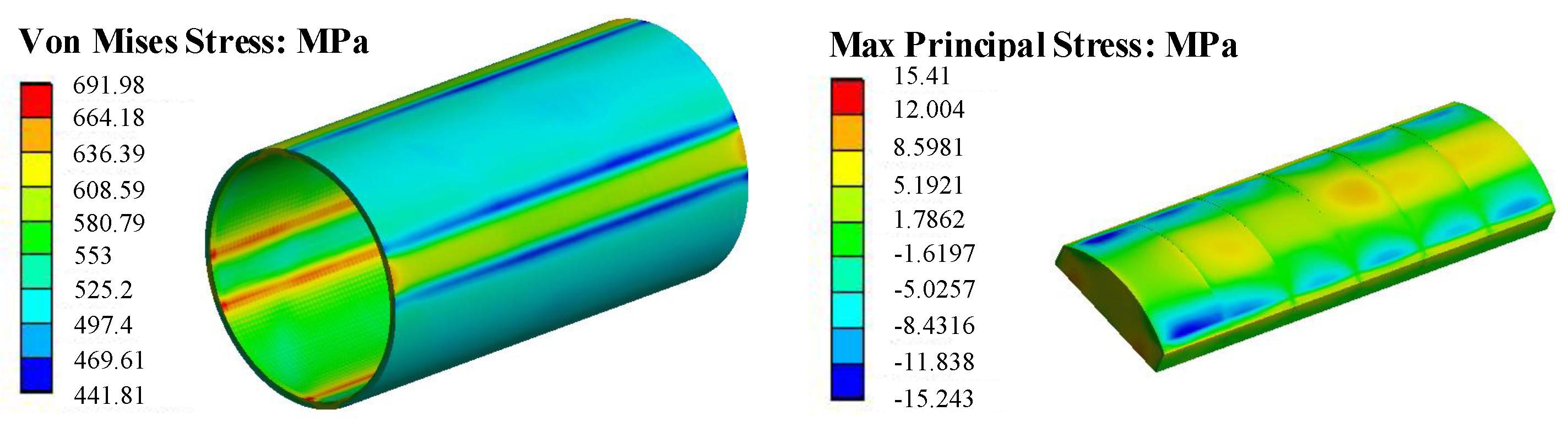
Furthermore, the rotor temperature distribution calculated by fluent is imported into the stress analysis as the setting condition. Through coupling calculation, the equivalent stress distribution of the rotor sleeve is calculated, as shown in
Figure 10. The maximum Von Mises stress of the sleeve is located at the junction of PMs and fillers inside the sleeve, and the maximum value is about 692 MPa, which is significantly lower than the maximum allowable stress of Inconel 718. On PM, the maximum tensile stress appears near the hub, and the maximum tensile stress is 15.4 MPa, which is much lower than the maximum tensile stress of 78 MPa. The fluent-stress coupling analysis shows that the thickness of the sleeve and shrink fit selected in the design is reasonable and can meet the requirements of the high-speed operation of the prototype.
5. Experiments and Analysis
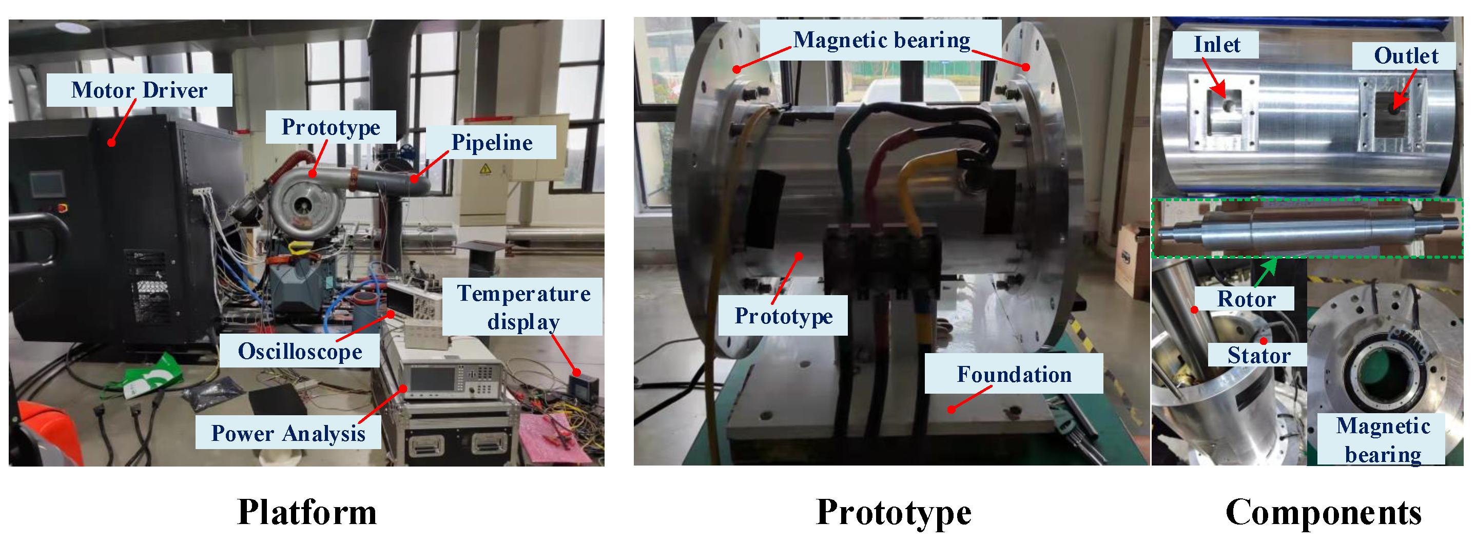
The prototype test platform and the pictures of each component are shown in
Figure 11. The prototype adopts magnetic bearing and is cooled by axial ventilation cooling. An inlet and an outlet are arranged along the axial direction on the housing. In the process of the rotor assembly, the assembled permanent magnet and rotor yoke are cooled by liquid nitrogen, then loaded into alloy sleeve, and finally restored to normal temperature. In this way, the high-temperature demagnetization of magnets that may occur with the hot sleeve process can be avoided.
One side of the motor is connected with an impeller and a volute, and an external pipeline realizes air transportation. In the test platform, the power analyzer is used to measure input power, power factor and so on, and the sensor is used to record the stator winding temperature in the slot; a temperature display is used to display and record it. The waveform of the load current and terminal voltage is obtained by Oscilloscope. The prototype is controlled by the motor driver, in which the switching frequency is 8 kHz and the carrier ratio is 12.
The focus of the test is to confirm whether the motor can achieve safe operation. Therefore, a long period of rated operation is carried out, and the machine is shut down after several hours of operation. A load test is performed after the motor is restored to room temperature. In a new round of experiments, the rotor stress can be verified to meet the requirements for safe operation.
The speed and temperature curve are shown in
Figure 12, and the motor reaches thermal stability in about 40 min after the prototype runs at 20,000 r/min. The motor is controlled to run at 19,000 r/min, and the speed curve of the motor speed increase process indicates that the rotor is not damaged. Then, the speed is reduced to 10,000 r/min, and gradually increased from 10,000 r/min to 20,000r/min.
At this point, the measured temperature of the winding in slots is 109 °C, slightly higher than 107 °C as shown in
Figure 9. The error of the simulation results is very close to that of the experimental results, which verifies the correctness of the simulation and analysis.
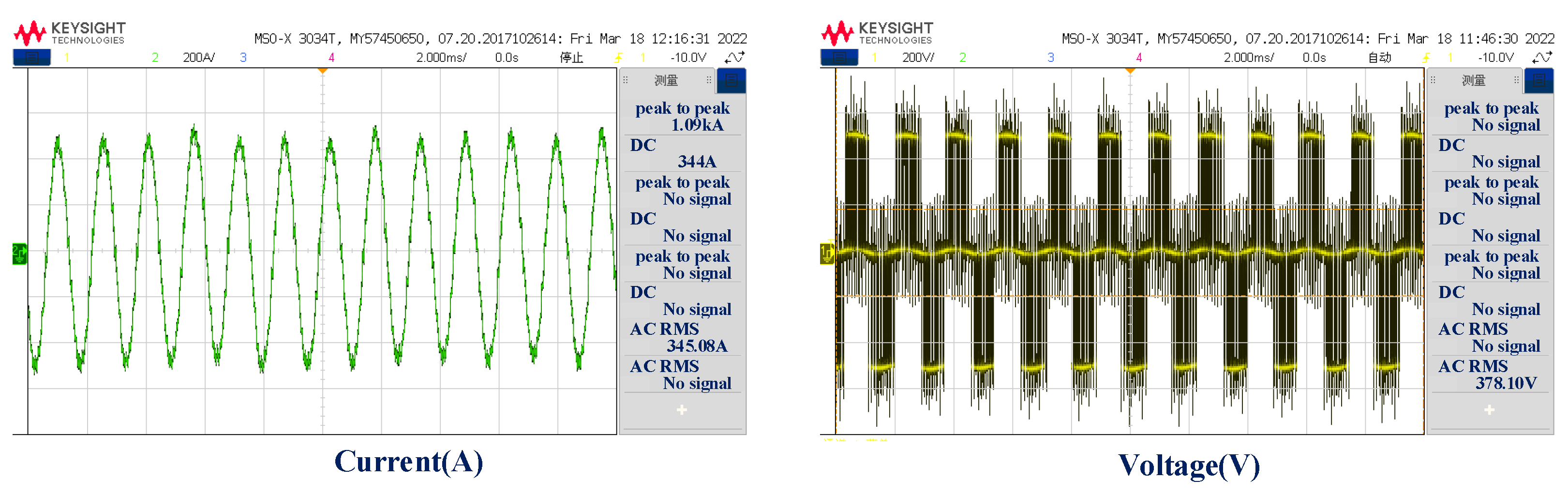
The waveform of current and voltage measured when the prototype runs at 20,000 r/min is shown in
Figure 13. The amplitudes of harmonics included in the current waveform are shown in
Table 7. The fundamental amplitude of the current is 484.87 A (peak) and THD is 6.1%. In addition, even harmonics appear in the decomposition results of the current waveform. This may be due to the fact that when the carrier ratio (carrier frequency/motor frequency) of the system is low, PWM modulation produces even harmonics, mainly the second harmonic. The lower the modulation index, the higher the second harmonic content.
6. Conclusions
In this paper, a 200 kw 20,000 r/min high-speed permanent magnet motor with a magnetic bearing is used as the object, and the influence of the permanent magnet structure, the filler material between the poles, and the choice of different sleeve thickness and shrink fit on the rotor stress is studied in detail. The value of sleeve thickness and shrink fit and the rotor stress are checked by the coupled calculation of fluent and static stress and experiments. Some key points are summarized below:
- (i)
For the magnet structure with a pole arc coefficient less than 1, the addition of the fillers creates the original uniform stress distribution on the sleeve, and the stress suddenly increases at the contact position between the fillers and the PMs. The thermal expansion coefficient is an important indicator when selecting a filler material, and should be close to that of the PMs used in the rotor.
- (ii)
The setting of sleeve thickness and shrink fit is very important in rotor stress design analysis. On the premise of considering eddy current loss, the size that meets the design requirements of the prototype is determined through a comprehensive analysis.
- (iii)
For the values of sleeve thickness and shrink fit obtained above, considering the axial temperature gradient caused by axial ventilation cooling, we use fluent to calculate the temperature distribution of the motor, and import the temperature distribution results into the static stress analysis. The coupling calculation results and experimental results demonstrate the correctness of the theoretical analysis.
Through the analysis in this paper, it can be concluded that in the checking of the rotor strength of a high-speed motor, the same temperature can be applied to rotor components in order to quickly understand the distribution characteristics and influencing factors of rotor strength. However, for axial forced air cooling, in order to obtain more accurate calculation results and ensure the safe and reliable operation of the motor, it is necessary to consider the axial temperature difference caused by cooling methods and the corresponding strength check.


