1. Introduction
Maglev is the abbreviation of Magnetic Levitation. EMS (Electro-Magnetic Suspension) technology is a typical suspension technology of maglev trains, which has the advantages of low noise and pollution, small turning radius, and strong climbing ability and it has attracted attention widely [
1,
2,
3]. At present, there are two mature EMS medium-and-low-speed maglev commercial lines in China, which are located in Changsha and Beijing [
4,
5,
6], and several maglev experimental lines. At the same time, new EMS medium-and-low-speed maglev commercial lines are being planned and constructed, such as the Fenghuang line, the Qingyuan line, etc. In the development of the EMS medium-and-low-speed maglev train, the improvement of train operation speed is a widely concerning problem. The speed of the EMS medium-and-low-speed maglev train in commercial operation is usually 60–80 km/h, but in fact, it has the ability to reach a higher speed. During engineering experiments, the operation speed of the EMS medium-and-low-speed maglev train can reach 160 km/h or even higher [
7].
In order to achieve high-speed or even ultra-high-speed with this structure, the influence of the eddy current effect on the suspension system is a crucial issue that needs to be solved. The F-shaped rail of the EMS medium-and-low-speed structure is usually made of steel, which is a kind of material with both magnetic conductivity and electrical conductivity [
8,
9]. When the maglev train is in motion, the moving magnetic field will generate induced current in the conductive rail due to electromagnetic induction. Because the induced current usually flows in a vortex, it is called eddy current [
10]. The calculation of eddy current has been studied in some literature. M. Passarotto et al. [
11] have addressed the solution of eddy-current problems by means of a volume integral formulation based on the electric vector potential on a computational domain that exhibits a cyclic symmetry. Frljić et al. [
12] have presented a two-step method for the calculation of eddy currents and eddy current losses in an open-core transformer. A. Hoxha et al. [
13] have proposed a fast solution to the eddy current problem for two moving conductors by using the integral formulation in the frequency domain.
Different from the common calculation of eddy current loss in the iron core, the influence of eddy current on the suspension system is mainly reflected in the change of the suspension force. This problem has attracted the attention of many scholars, and the main research methods include theoretical analysis, numerical simulation, and experimental verification.
In terms of theoretical analysis, the main research includes analytical solution and parameter fitting. Yamamura et al. [
14] deduced the analytical solution of the magnetic field equation of the suspension gap and calculated the formula of the electromagnetic force. Then, the variation curves of the magnetic field and electromagnetic force with speed are drawn according to the calculation results. For this analysis process, Zheng [
15] gave a more detailed derivation process and obtain some similar conclusions. Yang et al. [
16] obtained a model which can describe the system more accurately using the formula from [
15]. Yu et al. [
17] studied the suspension system model composed of four suspension magnets and calculated the suspension force of each magnet under the influence of eddy current. Liu et al. [
18] approximately obtained the formula that
. Where,
is the suspension force influenced by the eddy current,
and
are obtained by fitting the solution of the three-dimensional finite element method. Li et al. [
19] introduced coefficient
to correct the magnetic flux density, and
is obtained according to the simulation results. Machado [
20] established a two-dimensional model composed of conducting sheet and infinite length coil, and its basic principle is consistent with EMS maglev train. By introducing the magnetic vector potential, the analytical electromagnetic field of a conductive thin plate with the eddy current effect is derived.
At present, most of the research on theoretical analysis simplifies the suspension system model to a two-dimensional model, and basically there is no research on a three-dimensional model. Numerical simulation can make up for this deficiency. Many scholars have observed the influence of the eddy current effect by establishing two-dimensional or three-dimensional simulation models. Du et al. [
21] used the commercial software JMAG-Studio to carry out numerical analysis on the single suspension magnet model and calculated the distribution of the eddy current density and the magnetic flux density at speeds of 0 km/h, 108 km/h, and 216 km/h, respectively. The calculation results showed that the eddy current density increases with the increase of speed. Ohsaki et al. [
22] established the single suspension magnet model, single module model, and multi suspension magnets model based on the HSST (High Speed Surface Transport) maglev train. The results once again showed that the eddy current density increased with the increase of speed, resulting in the decrease of the magnetic flux density and the suspension force. Zheng [
15] established the single suspension magnet model and single module model based on the CMS maglev train and conducted a three-dimensional transient magnetic field simulation with the help of finite element simulation software Ansoft. Then, the numerical solution of the eddy current effect is obtained and compared with the analytical solution. Ding et al. [
23] used Maxwell software to establish the models of one suspension module and two suspension modules, respectively, and analyzed the changes in eddy current density, the magnetic flux density, and the suspension force at different speeds. Zhai et al. [
24] used Maxwell software to establish a finite element model. The numerical simulation results showed that in the process of high-speed running, the distribution of the magnetic flux density changed significantly, which seriously affected the suspension electromagnetic force.
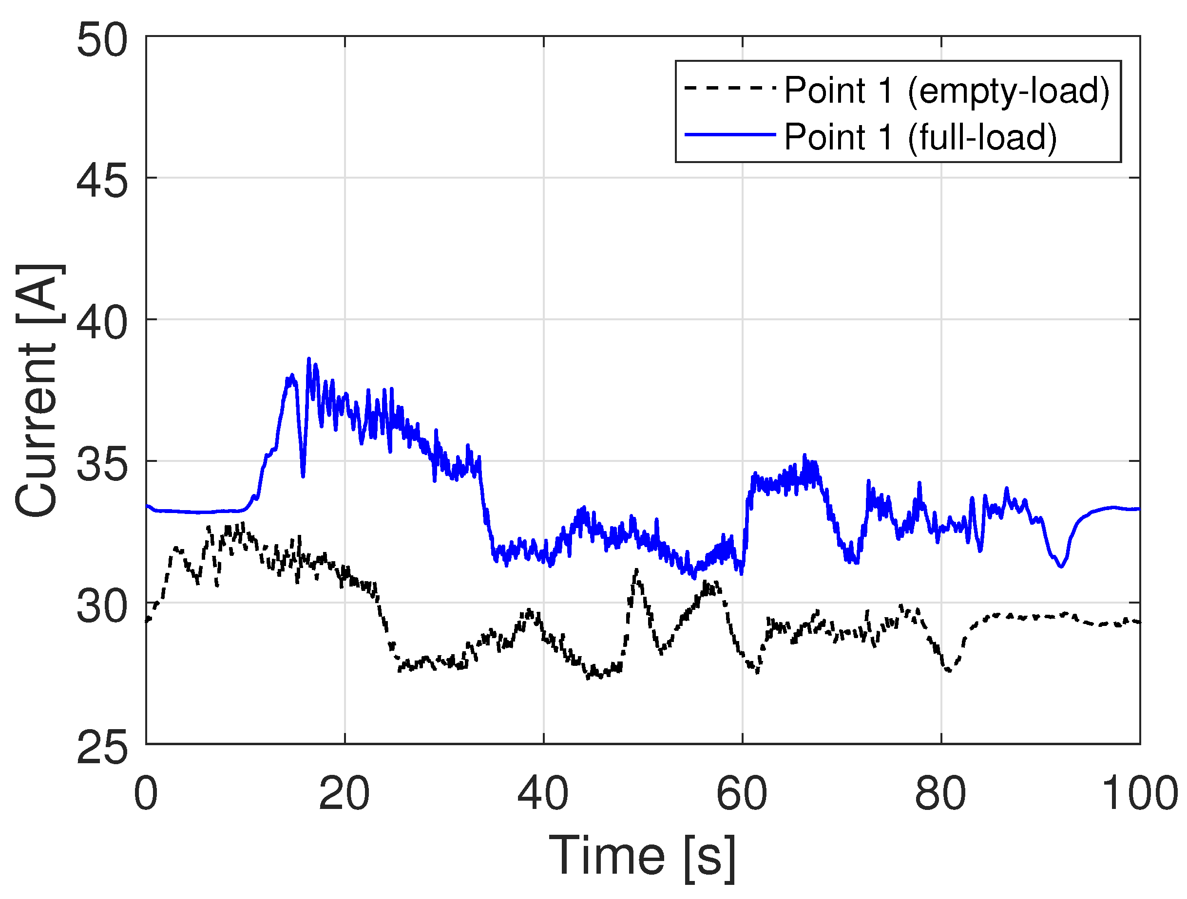
During the experiment, the influence of the eddy current effect can be judged by observing the suspension current data. Because the eddy current attenuates the suspension force, the suspension system will increase the suspension current to ensure the required suspension force. Zheng [
15] conducted experiments of the maglev train with three carriages on the Tangshan maglev experimental line. The results showed that the eddy current does reduce the suspension force, which is consistent with the theoretical analysis. Ding et al. [
23] listed the experimental data of the suspension current at the speeds of 0 km/h, 60 km/h, and 90 km/h. The results showed that the higher the speed, the greater the suspension current. Yang et al. [
25] gave the suspension current data of the Changsha maglev line. The results showed that with the increase of the speed, the suspension current of the front magnet increased to 1.54 times that of the stationary state and 1.37 times that of other suspension magnets. On the whole, experimental data on the influence of the eddy current effect on the suspension system in publications are few. In addition, only a few current values are given in the existing experimental results. In this article, the experimental data of the maglev train with six carriages will be analyzed. Unlike existing research, these experimental data are the continuous current values.
Scholars generally believe that the influence of the eddy current effect on suspension force cannot be ignored, especially when the train runs at a high speed. In order to suppress the influence of the eddy current effect, scholars have put forward different kinds of solutions. From the perspective of the suspension control algorithm, Yang et al. [
16] used an effective PD controller to control the established suspension system model. Liu et al. [
18] used a variable universe adaptive fuzzy controller with speed compensation to control the established system model considering the eddy current effect. Zhai et al. [
24] achieved the dynamic adjustment and parameter optimization of the existing nominal controller and improved the robustness of the suspension system. The current fluctuation caused by eddy current can be reduced by optimizing the control algorithm. However, this method has some limitations because the suspension force provided by the electromagnet has an upper limit. Facing the seriously attenuated suspension force, it is more effective to put forward improvement methods from the perspective of the structure of the suspension system. Zheng [
15] proposed a scheme, to add a permanent magnet on the suspension electromagnet at the front of the maglev train. The principle is to establish the magnetic field in advance through the permanent magnet. Yu et al. [
17] proposed a new suspension module composed of five suspension magnets. The principle is similar to the reference [
15]. Yang et al. [
25] proposed two new schemes, which are changing the structure of the air spring and suspension magnet, respectively. After calculating the effectiveness of these two schemes, the improved suspension magnet scheme is used in the maglev train version 2.0 with a design speed of 160 km/h. Hardly any scholars put forward solutions to this problem from the perspective of rail structure. In fact, this is also a feasible idea. The rail of the Shanghai maglev line is made of 0.5 mm silicon steel sheets and effectively prevents the generation of induced eddy current [
26]. For the EMS medium-and-low-speed maglev train, such a rail structure can be used for reference.
The following contents are as follows. In
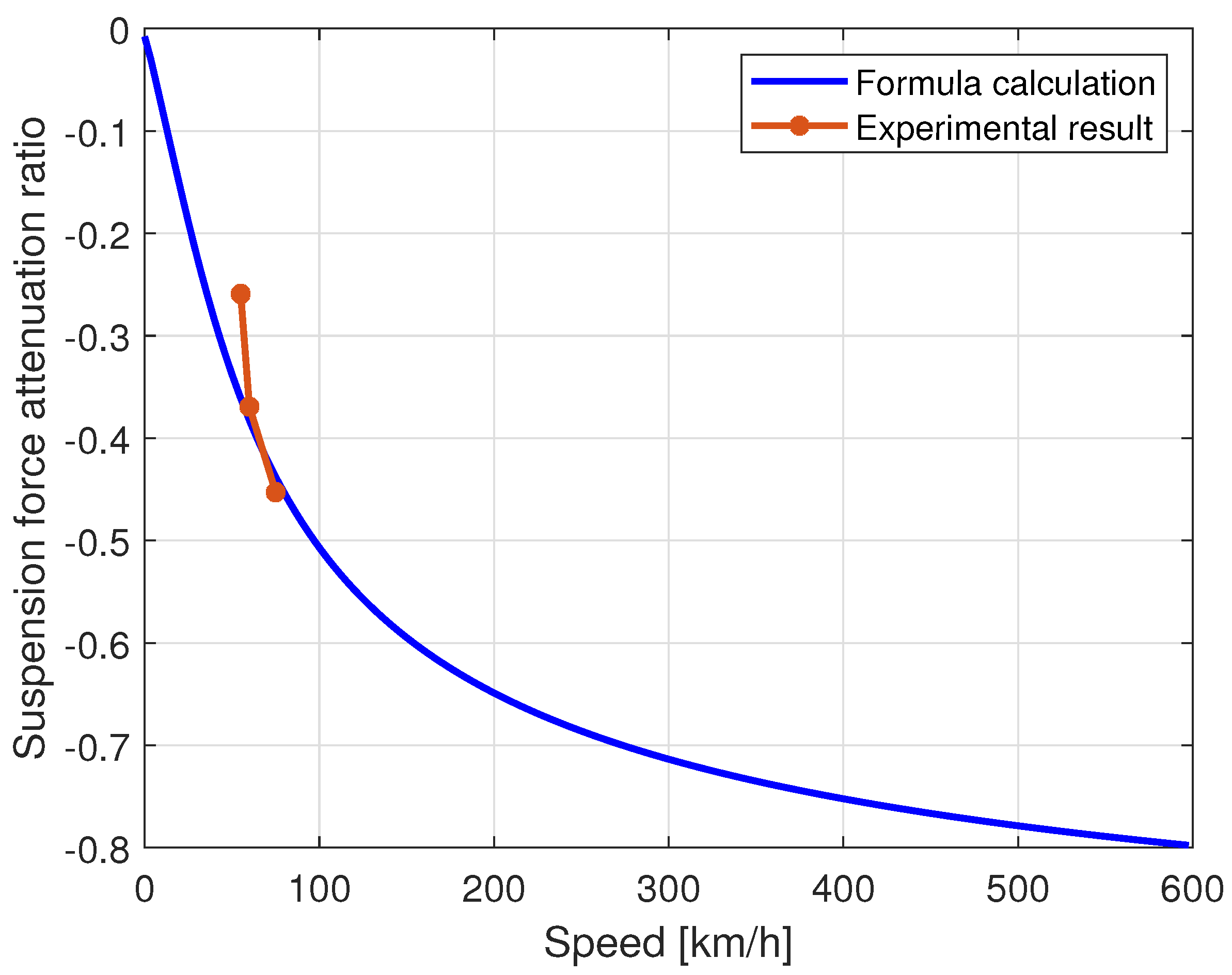
Section 1, the formula of the suspension force considering the eddy current effect is derived. By observing the parameters of the formula, the factors affecting the eddy current effect are obtained. In
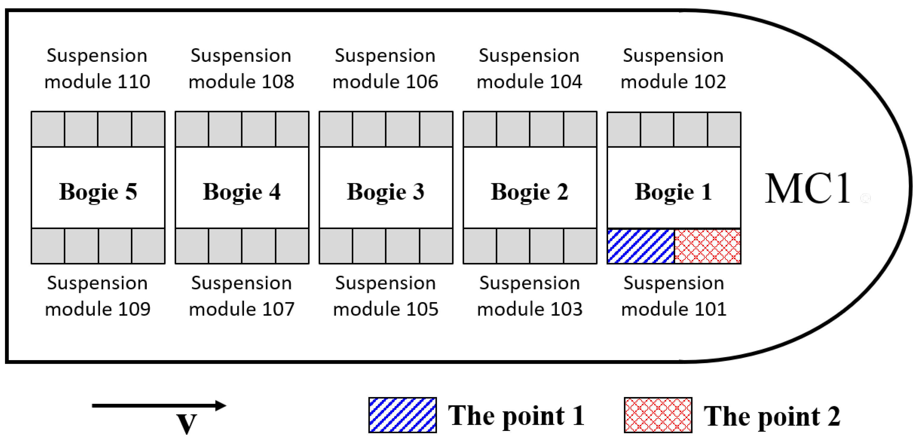
Section 2, the experimental verification is carried out on the Tangshan maglev experimental line. In
Section 3, three kinds of rail structures are proposed, and the effectiveness of these new structures is verified by the three-dimensional transient field simulation.
Section 4 is the summary and prospect.
2. Theoretical Analysis
As mentioned in the Introduction, the eddy current effect will affect the suspension force of the maglev train. This section will mathematically describe this phenomenon through theoretical analysis. Thus, the suspension system model is established firstly.
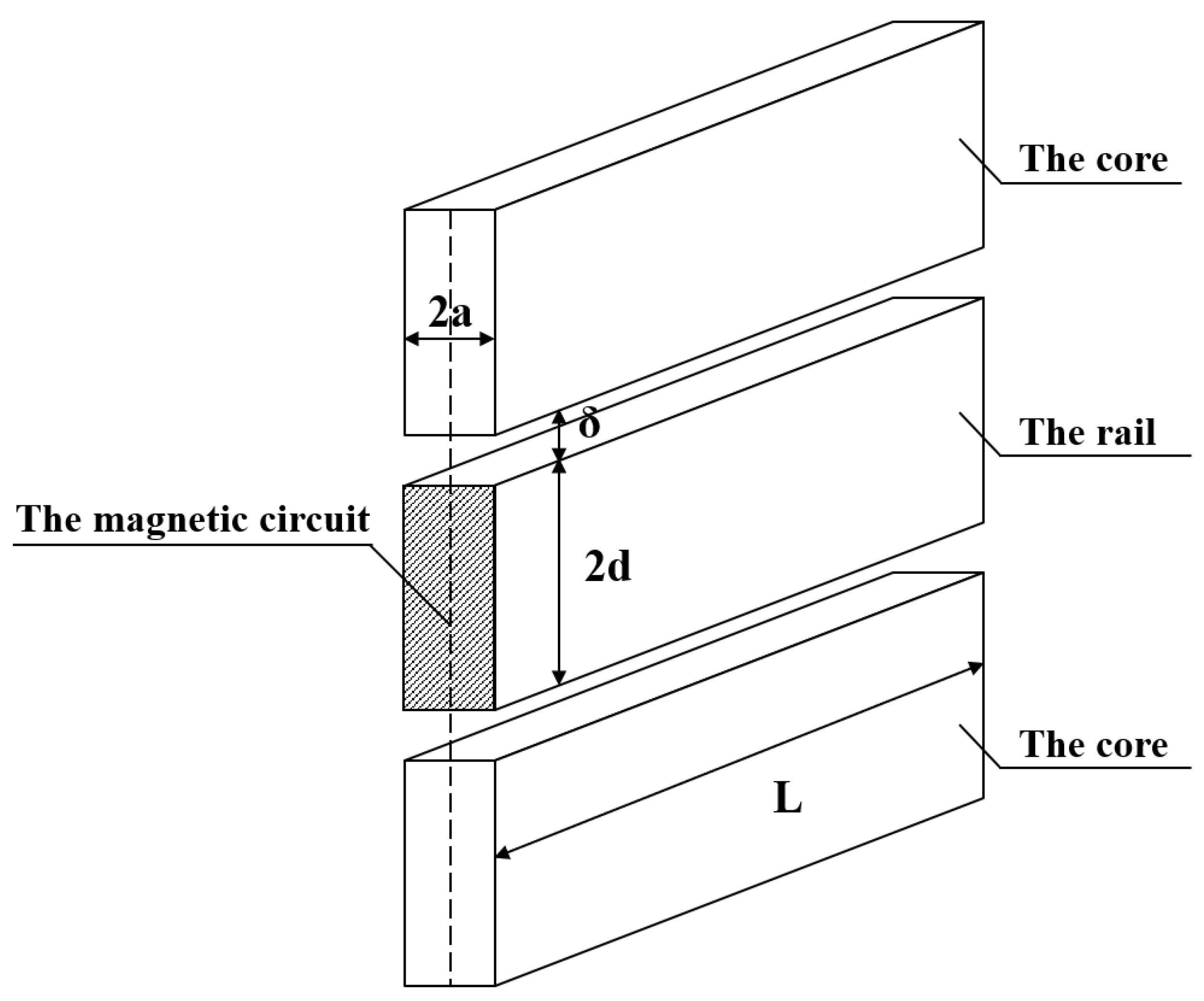
The single suspension magnet model can be regarded as the smallest unit of the suspension system [
27], whose three-dimensional structure and two-dimensional section is shown in
Figure 1 and
Figure 2, respectively. Where the rail is a simplified U-shaped solid structure, and under the rail is a suspension magnet that is composed of the iron core and the coil. In order to calculate the eddy current effect conveniently, the single suspension magnet model shown in
Figure 1 is equivalent to the model shown in
Figure 3 [
15]. The meanings, values, and units of relevant parameters in the suspension system are shown in
Table 1. The value of each parameter is selected according to the actual situation in the commercial maglev line. It is worth noting that
is the width of one side of the inverted U-shaped rail, and
is the height after expanding the inverted U-shaped rail into the line shape.
Ignoring the reluctance and magnetic leakage in the iron core, then
where,
,
,
, and
S are the reluctance, the suspension gap, the permeability in vacuum, and the pole area, respectively. As
Table 1 shows,
represents the rail width and
L represents the length of the suspension magnet, then
. Since the total magnetic potential in the magnetic circuit is
, where
N represents the number of windings,
I represents the suspension current. Let
represent the magnetic flux in the circuit, and according to the Ohm’s law of magnetic circuit [
28], the
can be written as
Further,
B is the magnetic flux density in the magnetic circuit and can be obtained as
According to
Figure 1, the volume in the suspension gap is
. Therefore, the magnetic field energy
in volume
V can be obtained as
where
H is the magnetic field intensity in the suspension gap. Let
represent the suspension electromagnetic force without considering the eddy current effect. Then the
can be obtained as
When there is an eddy current effect in the rail, the suspension force
is
where
,
,
,
, and
. Noting that Formula (
6) only considers the fundamental part of the magnetic field and ignores the high-frequency component.
As can be seen from Formula (
6), the main parameters affecting the suspension force are: the permeability in air gap
, the rail conductivity
, the rail height
, the rail width
, the length of the suspension magnet
L, the train running speed
v, the suspension air gap
, and the ampere turns of the suspension electromagnet
. Among the above parameters,
is a constant; once the rail material is determined,
is also a constant and difficult to change;
v,
, and
are parameters affected by the running state of the train. Therefore, in order to suppress the generation of induced eddy current in the rail, it is better to optimize
,
, and
L. In the Introduction, it is mentioned that scholars have studied the scheme of adding a suspension magnet, which is the scheme of changing
L. In addition, this article will research from the perspective of changing
, which will be described in
Section 3.
4. Improvement Scheme
In order to suppress the influence of the eddy current effect on the suspension system, the improvement scheme from the perspective of the rail structure is put forward in this section, which includes three rail structures: type I, type II, and type III.
Figure 11,
Figure 12 and
Figure 13 show their cross-sections, which are improvement models based on the reference [
15]. Call the model in reference [
15] the original simulation model. The consistency between the original simulation model, the theoretical model, and the physical model has been explained in reference [
15] and will not be repeated in this article. This section focuses on the effect of the improvement models.
In
Figure 11,
Figure 12 and
Figure 13,
= 9.3 mm,
= 0.19 mm,
= 5.6 mm and
= 0.11 mm. So that the duty ratio of the improvement models is the same. When using the simulation software ANSYS MAXWELL for the electromagnetic field analysis, the operation steps are as follows.
Step 1: Build the model. In this article, the simulation model is established in the three-dimensional transient field and its three-dimensional structure is shown in
Figure 14. Set the single suspension magnet to move forward at the speed
v along the positive direction of the Y axis. At present, the EMS medium-and-low-speed maglev train can achieve a maximum speed of 160 km/h. The research of this article is devoted to improving the train speed, so a higher and reasonable speed of
v = 300 km/h is set.
Step 2: Define material properties. The coil material is aluminum. The material of the rail and the suspension magnet is Q235, whose magnetic flux density reaches saturation at about 1.4 T, conductivity is S/m, and density is 7850 kg/m3.
Step 3: Set boundary conditions. Use the create-region operation to draw the solution domain in the outermost part of the whole model. Where the padding type is percentage offset and the padding data are set as 500 in the X and Z directions and 100 in the Y direction. The boundary condition is set as zero tangential H field.
Step 4: Set excitation. The number of turns is 360 and the current is 35 A.
Step 5: Set solution parameters. Assign the suspension force of the rail.
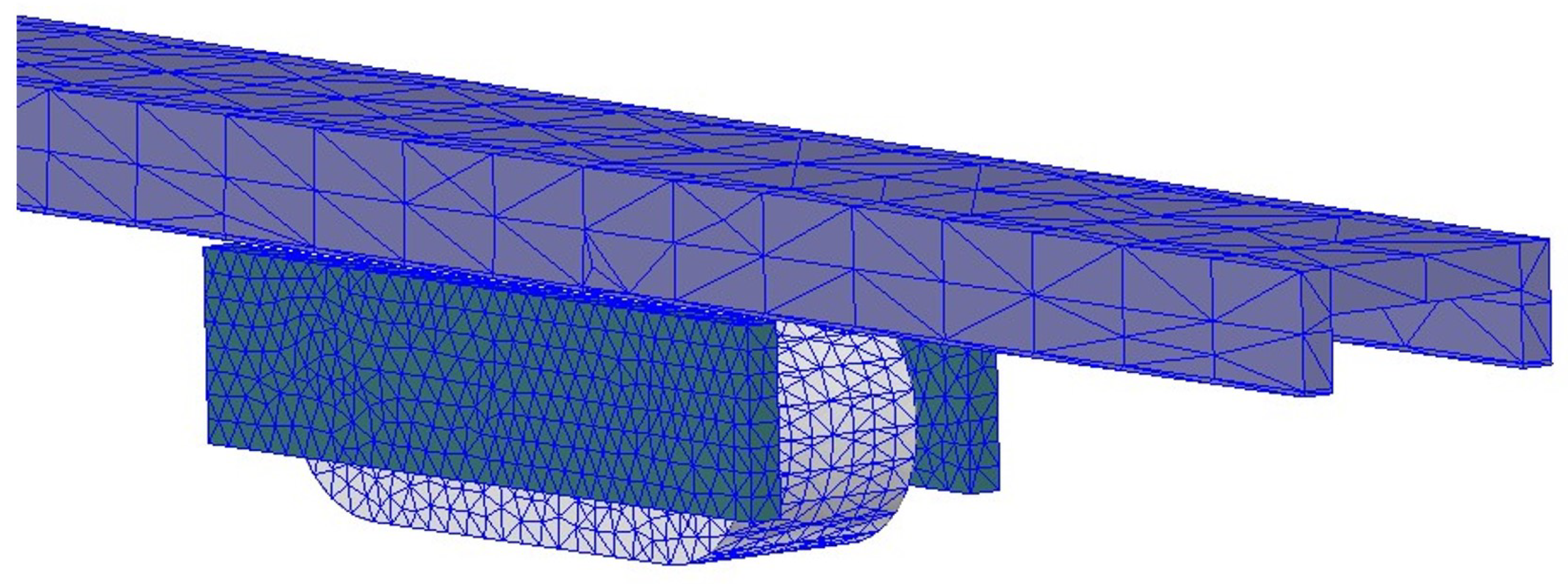
Step 6: Set the mesh. The method of manual division is used to limit the maximum size of the mesh. The mesh generation effect is shown in
Figure 15.
Step 7: Set the solver. The simulation step in the solver is 0.0001 s and the simulation time is 0.06 s when the speed v = 300 km/h.
When the suspension magnet moves forward along the positive direction of Y axis at speed v, the amplitude of the suspension force will change from large to small and gradually stabilize under the influence of the eddy current effect. There is no induced eddy current in the rail at the initial time, and the suspension force is the maximum at this time. In the simulation results, it is about 7 kN. When the amplitude of the suspension force is stabilized, the suspension forces of type I, type II, and type III rail are 5.80 kN, 6.59 kN, and 6.89 kN, respectively. This shows that at the same speed, decreasing the laminated width can increase the suspension force.
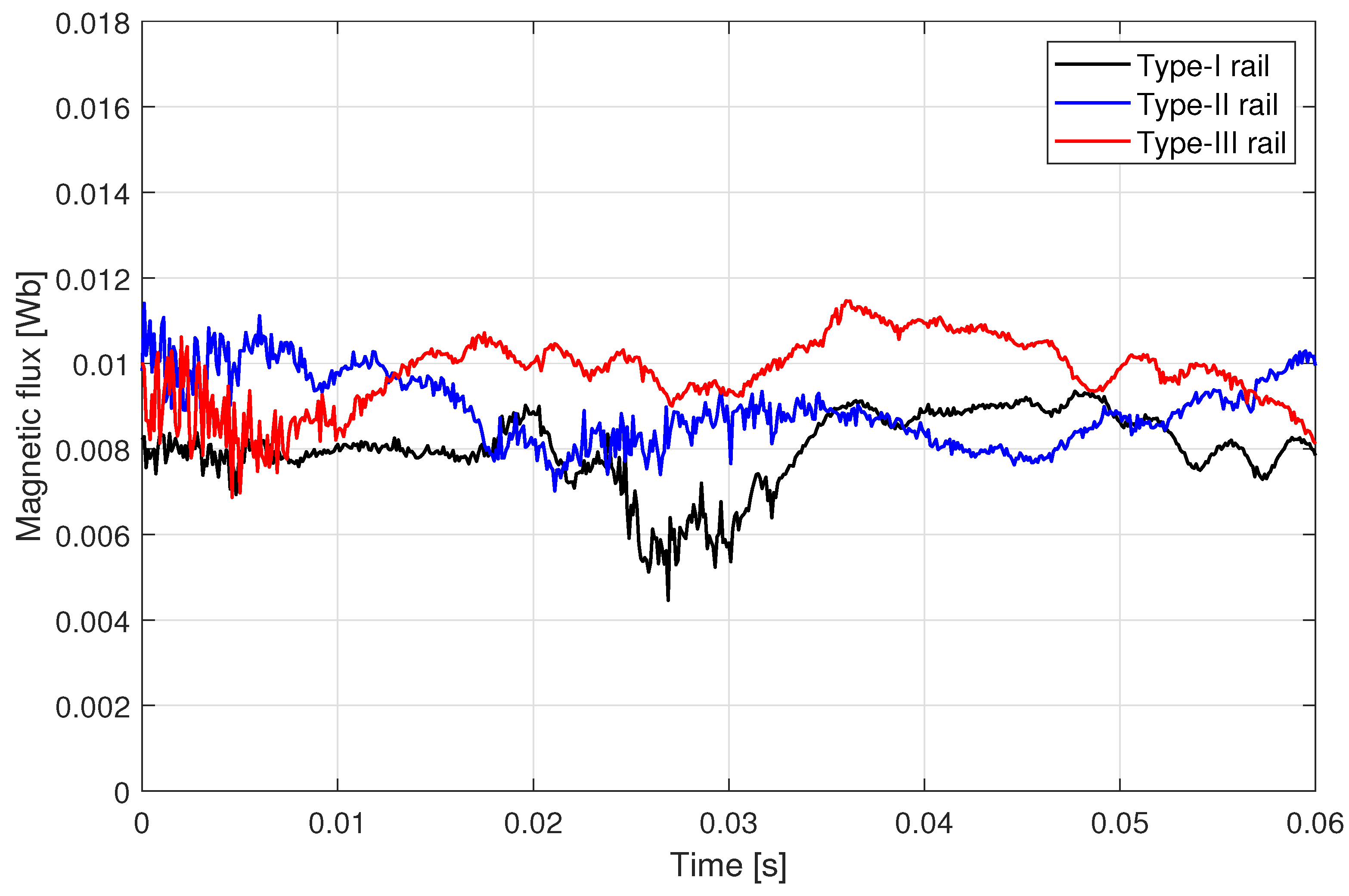
In order to observe the variation of the magnetic field quantitatively, reference plane 1 is set. The size of reference plane 1 is the same as the XY plane section of the rail. Moroever, the position of reference plane 1 is shown in
Figure 16. Since the suspension force is mainly generated by the component of the magnetic field along the Z axis, the component of the magnetic flux density along the Z axis
is observed. After integrating
along reference plane 1, the magnetic flux
can be obtained.
Figure 17 shows the magnetic flux
changes with time. It can be seen that at the same speed, the smaller the laminated width, the greater the magnetic flux.
In order to observe the variation of the eddy current quantitatively, reference line 2 is set as shown in
Figure 18. Where reference line 2 is 4 mm away from the rail edge. It starts at the point M and ends at the point N. The suspension magnet moves from the point M to the point N at speed
v. With the help of reference line 2, the change of the eddy current density amplitude
in the rail can be observed quantitatively, and the results are shown in
Figure 19. Where, the initial value of the abscissa is 0 m, representing the position of the point M, and the final value of the abscissa is 6.98 m, representing the position of the point N. It can be seen that at different times, the suspension magnet moves to different positions, and the peak value of the eddy current density amplitude appears at the corresponding position. The eddy current density amplitude at the front is the largest. At the same speed, the eddy current density amplitude of type I rail is the maximum and that of type III rail is the minimum, especially in the front position. It means that the smaller the laminated width, the smaller the eddy current density in the rail.
5. Summary and Prospect
This article studies the influence of the eddy current effect on the suspension system of the EMS medium-and-low-speed maglev train, which is a crucial problem related to improving the operation speed of the maglev train.
Firstly, the formula of the suspension force is deduced considering the influence of the eddy current effect and experiments are carried out on the Tangshan maglev experimental line. In particular, the current values during the train runs have never been given in such detail in previous research. These data are important because they show the influence of eddy current more clearly. In addition, these data are objective and authentic since they are verified by several experiments.
Secondly, a solution to suppressing the eddy current effect is proposed in this article. The feasibility of applying the lamination technology to the rail used in the EMS medium-and-low-speed suspension system is studied for the first time. This research makes important progress on the improvement of the rail used in the EMS medium-and-low-speed maglev train.
The next work includes the following aspects. (1) Verify the effect of the improvement scheme proposed in this article in engineering applications, and explore the upper limit of the speed. (2) The situation that magnetic materials do not have flux saturation is studied in this article, which is the most common situation in engineering. In order to study it more comprehensively, the effect of the nonlinear behavior of magnetic materials needs to be considered. (3) Although only considering the current fundamental component can meet the needs of engineering, it is necessary to study the influence of the small harmonic components in the current quantitatively in order to improve the accuracy of the model.


