Article

Synchronization of Four Axisymmetrically Distributed Eccentric Rotors in a Vibration System

School of Control Engineering, Northeastern University at Qinhuangdao, Qinhuangdao 066004, China
*
Author to whom correspondence should be addressed.
Machines 2022, 10(6), 457; https://doi.org/10.3390/machines10060457
Submission received: 12 May 2022 / Revised: 2 June 2022 / Accepted: 6 June 2022 / Published: 8 June 2022
(This article belongs to the Section Machine Design and Theory)

Abstract

:
This paper studies synchronization of a class of even pairs and symmetrically distributed eccentric rotors in a vibration system of a single mass body. A vibration system driven by four ERs with circular distribution structure and the same rotating direction is adopted as the dynamic model. The motion differential equations of the system are established based on Lagrange equation. The angular velocity and the phase of each rotor are perturbed by the average value of the synchronous velocity. The state equation of the system is obtained by applying the averaging method. According to the necessary condition of the steady-state motion, the synchronization condition and the dimensionless coupling torques of the system are deduced. The stability condition of the synchronous motion is derived by applying Lyapunov indirect method. The distribution law of the steady-state phase difference is discussed qualitatively by the numerical analysis of the theoretical results. Then combined with the numerical results, five sets of experiments are carried out on the experimental machine, which includes the sub-resonant state and the super-resonant state. The experimental results show that this vibration system has two super-resonant motion states and one sub-resonant motion state. The experiment proves the correctness of the theory, which can provide theoretical guidance for the design of this kind of vibration machine.

1. Introduction

The synchronization phenomenon widely exists in nature, which means that two or more objects have the same or similar motion state. For synchronization of mechanical systems, Blekhman [1,2] is the first person to theoretically explain the synchronization problem of two identical eccentric rotors (ERs) with the method of direct separation of motion. The discovery of synchronization mechanism and application have aroused the enthusiasm of scholars from all over the world for the study of synchronization theory, and a number of useful machines have also been invented. The machines mainly focus on pendulum synchronization and ER synchronization. In the study of pendulum synchronization, Czolczynski et al. [3,4] established a two degree of freedom model of a cantilever beam system. Then he studied the dynamic properties of two self-excited pendulums on a vibration beam. In the research of ER synchronization, Kibirkštis et al. [5] used the pneumatic channel to study the synchronization problem of the pneumatic ER in the state of self-excited vibration under the pulsating pressure of the feed. Miklós et al. [6] proposed a new design structure of double ERs, which can generate vibration with independently adjustable frequency and amplitude. Gu et al. [7] studied synchronization of ERs and the cylindrical roller in the super-resonant vibration system, which is helpful in solving practical problems such as vibration crushers and vibration grinders.
Compared with pendulum synchronization, ER synchronization is more useful in engineering applications to design vibration machines. To get the maximum force, Chen et al. [8] proposed a new method to achieve zero phase difference between two ERs for vibration system with different structural parameters by adjusting the power supply frequency of motors and verified the feasibility of the method using experiments. After that, Chen et al. [8,9] studied the synchronization problem of two co-rotating shaft ERs in the far-resonant state, which provides a guide for designing a kind of vibration grinder. In fact, not only the same frequency has the phenomenon of synchronization, but multi-frequency also has the synchronous application. Zou et al. [10] studied multi-frequency synchronization of two ERs through theoretical derivation and experimental analysis. Li et al. [11] established the mechanical model of two ERs with opposite rotation directions and different rotational velocities, and pointed out the application prospect of multi-frequency synchronization theory in engineering. The models in the above studies are all plane motions, and the spatial motions are mentioned below. Based on the modified small parameter method, Zhao et al. [12] studied the synchronous problem of the staggered installation model of two ERs in the spatial motion mechanical system, which provided a guideline for the design of a class of screw feeder. Using the Poincare method and Hamilton principle, Fang et al. [13] studied the spatial synchronization of two ERs installed in parallel in the far-resonant state, which provides a new way for designing a new type of vibration screen. Single mass body is studied in most of the above papers and two mass bodies are introduced below. Chen et al. [14] proposed a model in which two ERs drive two masses respectively and discussed the coupling dynamics between two masses. Shishkin et al. [15] designed the two masses vibration crusher with two ERs mounted on the outer mass. ER drives the inner and outer two masses to move in opposite directions so as to achieve the effect of crushing materials. The above papers studied linear systems and the following are nonlinear systems. The vibration system is a multi-rigid coupled system, so the steady-state motion of the vibration system is affected by many kinds of influences. Djanan et al. [16] discussed the influence of the physical characteristics of the motor on the phase difference when two ERs reach the synchronous state. Introducing nonlinear springs, Li et al. [17] studied synchronization theory of nonlinear systems.
The above studies focused on the synchronization of two ERs. In order to meet the needs of large-scale vibration machines, manufacturers began to develop vibration machines driven by multi-ERs. However, the fact has been proved that vibration system driven by three ERs is not suitable for industrial application. By investigating the dynamics of three horizontally mounted ERs, Zhang et al. [18] found that replacing two ERs with three ERs could not improve the effective power of the system. In order to overcome the above shortcomings, control synchronization is an ideal way to achieve the synchronous motion of ERs with zero phase difference [19]. Chen et al. [20] established a coupled dynamic characteristic model of the horizontal installation of three ERs and verified that the vibration system has multiple synchronous states. Fang et al. [21] introduced control synchronization method in vibration system driven by ER and pendulum to obtain the ideal motion trajectory. Chen et al. [22] designed a controlled synchronous system consisting of three ERs, the coupling characteristics of the vibration system are analyzed according to the experimental data, which provides a guideline for the design of the vibration machine with control synchronization. Aiming at the problem that multi-frequency synchronization is difficult to achieve, Jia et al. [23] used the fuzzy control method to achieve the velocity and phase synchronization of three ERs.
Due to the property of the structure distribution of three ERs system, the synchronous characteristics of multi-ERs system cannot be fully reflected. Therefore, scholars began to investigate on the vibration system with the even-pair structural. Using the averaging method, Liu et al. [24] studied the synchronous stability capability of two pairs of counter-rotating ERs. Zhang et al. [25] studied the synchronization theory of four co-rotating ERs in two resonance regions. Kong et al. [26] studied the composite synchronous problem of four ERs, and the feasibility of the composite synchronous method was verified by numerical simulation. The above researches have promoted the development of four ERs system. However, the lack of experiments of four ERs hinders the development of vibration systems with the even-pair structure in engineering applications. To sum up, this paper takes four ERs structure as the object to study the synchronous characteristics of even-pairs ERs system. The structure of this paper is as follows: In Section 2, the dynamic model of the vibration system is given, and the differential equations of motion of the model are established; in Section 3, the response solution of the system is deduced, and the synchronization condition and the stability condition are obtained; the coupling dynamic characteristics of the system are numerically analyzed and the simulation results are given in Section 4; experimental results are provided in Section 5; finally, conclusions are given.

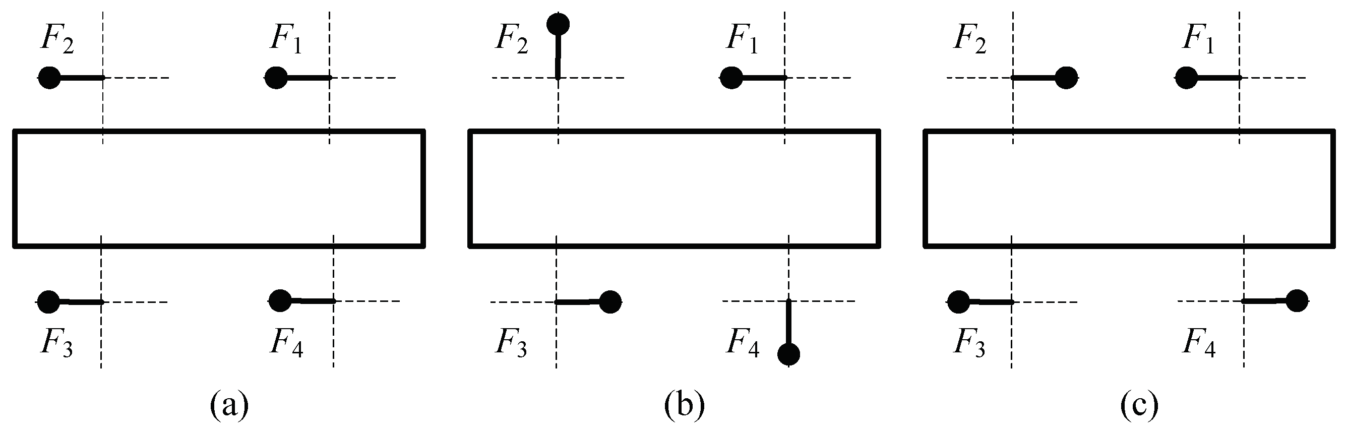
2. Dynamic Model and Motion Differential Equations

Figure 1a shows the dynamic model of four ERs circumferentially distributed on the rigid body. The body is supported by springs, and springs are symmetrically installed on body. m is mass of the rigid body; m 0 is mass of the ER; k i is stiffness of the vibration system and f i is damping constant of the vibration system in i direction, i = x, y, respectively; l 0 is the distance between motor eccentric block and rigid body center; β j is the motor mounting angle between four ERs and the x axis, j = 1, 2, 3, 4, respectively.
In Figure 1b, a fixed coordinate system oxy is established with the mass center as the origin. o 1 x 1 y 1 is parallel to the fixed coordinate system oxy. o 2 x 2 y 2 is a rotating coordinate system around o 1 . The system has 7 degrees of freedom which are the displacement in x and y direction, the rotation around axis ψ and motion φ i (i = 1, 2, 3, 4) of each rotor.
Based on Lagrange equation, the motion differential equations of vibration system can be obtained as follows [12]:
M x ¨ + f x x ˙ + k x x = m 0 r i = 1 4 ( φ ˙ i 2 cos φ i + φ ¨ i sin φ i ) M y ¨ + f y y ˙ + k y y = m 0 r i = 1 4 ( φ ˙ i 2 sin φ i φ ¨ i cos φ i ) J ψ ¨ + f ψ ψ ˙ + k ψ ψ = m 0 r l 0 i = 1 4 [ φ ˙ i 2 sin ( φ i + β i ) φ ¨ i cos ( φ i + β i ) ] ( J i + m 0 r 2 ) φ ¨ i + f i φ ˙ i = T e i m i r [ x ¨ sin φ i + y ¨ cos φ i + l 0 ψ ¨ cos ( φ i + β i ) + l 0 ψ ˙ 2 sin ( φ i + β i )
where M = m + 4 m 0 , k ψ = ( k x l y 2 + k y l x 2 ) / 2 , f ψ = ( f x l y 2 + f y l x 2 ) / 2 , J is the moment of inertia of the vibration system about its mass center.

3. Theoretical Derivation

3.1. Synchronization of Vibration System

According to the principle of linear superposition, the steady-state response solution of motion differential equations of the system excited by four ERs as follows [18]:
x = r m r μ x i = 1 4 cos ( φ i γ x ) y = r m r μ y i = 1 4 sin ( φ i γ y ) ψ = r m r μ ψ r l l e i = 1 4 sin ( φ i β i γ ψ )
where ω x = k x M , ω y = k y M , ω ψ = k ψ J , l e = J M , r l = l 0 l e , r m = m 0 M , ξ x = f x 2 M k x , ξ y = f y 2 M k y , ξ ψ = f ψ 2 J k ψ , n j = ω 0 ω j , μ j = n j 2 ( 1 n j 2 ) 2 + ( 2 ξ j n j ) 2 , γ j = arctan 2 ξ j n j 1 n j 2 ; γ j are the phase lag angle, ω j is the natural frequency of the system, ξ j is the relative damping coefficient of the system in j directions (j = x, y, ψ ).
If four ERs run synchronously, the relationship between each ER and the average phase is established as follows:
φ 1 = φ + 3 2 α 1 + α 2 + 1 2 α 3 φ 2 = φ 1 2 α 1 + α 2 + 1 2 α 3 φ 3 = φ 1 2 α 1 α 2 + 1 2 α 3 φ 4 = φ 1 2 α 1 α 2 3 2 α 3
where φ = 1 4 i = 1 4 φ i , φ i φ j = 2 α i , i = 1, 2, 3, j = i + 1.
If the vibration system runs stably, the average velocity of four ERs is φ ˙ = ω 0 = constant . Because the system do the period motion, the angular velocity and phase difference of ERs are perturbed by the average angular velocity [9]. The angular velocity and angular acceleration of four ERs can be set as follows:
φ ˙ i = ( 1 + ε i ) ω 0 , φ ¨ i = ε ˙ i ω 0 ,   i = 1 ,   2 ,   3 ,   4 ,
If four ERs run synchronously, the mean of the fluctuation coefficients of ε i in a single motion period of the system is zero. So, the system has capability of frequency capture. Using the averaging method of the nonlinear vibration system, the response solutions x ¨ , y ¨ , and ψ ¨ of the system are obtained by twice derivative on time t in Equation (2). Then substituting them into the last four formulas of Equation (1) and integrating φ = 0 ~ 2 π to get the mean differential equations as follows:
J i ω 0 ε ¯ ˙ i + f i ω 0 ( 1 + ε ¯ i ) = T ¯ e i T ¯ L i , i   =   1 ,   2 ,   3 ,   4 ,
where T ¯ L i = m 0 r 2 ω 0 2 ( χ f i + χ a i ) , i = 1, 2, 3, 4, denote the vibration torque of the system. The remaining symbols are defined in Appendix A (A1–A15).
When four ERs run synchronously, the motor output torque T 0 i can be obtained as follows:
T 0 i = T e 0 i f i ω 0 = m 0 r 2 ω 0 2 ( χ f i + χ a i ) , i   =   1 ,   2 ,   3 ,   4 ,
According to Equation (6), the synchronous motion is essentially an electromechanical coupling process. For the mechanical part, synchronization is the movement of four ERs with a constant phase difference and the same rotational velocity. For motors, synchronization means that the output electromagnetic torque of each motor is constant. Since the phase differences of ERs are constant, the differences between the output electromagnetic torques are constant. The differences Δ T i j between the output torques of motor i and motor j are obtained as follows:
Δ T i j = T i T j = T u τ c i j , i   =   1 ,   2 ,   3 ,   j   =   i + 1 ,
where T u = m 0 r 2 ω 0 2 / 2 represents the kinetic energy of ER;
τ c 12 = W s 1 W s 2 + W c s 13 cos ( 2 α ¯ 1 + 2 α ¯ 2 + θ s 13 ) + W c s 14 cos ( 2 α ¯ 1 + 2 α ¯ 2 + 2 α ¯ 3 + θ s 14 ) W c s 23 cos ( 2 α ¯ 2 + θ s 23 ) W c s 24 cos ( 2 α ¯ 2 + 2 α ¯ 3 + θ s 24 ) + 2 W c c 12 sin ( 2 α ¯ 1 + θ c 12 ) + W c c 13 sin ( 2 α ¯ 1 + 2 α ¯ 2 + θ c 13 ) + W c c 14 sin ( 2 α ¯ 1 + 2 α ¯ 2 + 2 α ¯ 3 + θ c 14 ) W c c 23 sin ( 2 α ¯ 2 + θ c 23 ) ] W c c 24 sin ( 2 α ¯ 2 + 2 α ¯ 3 + θ c 24 ) τ c 23 = W s 2 W s 3 + W c s 12 cos ( 2 α ¯ 1 + θ s 12 ) W c s 13 cos ( 2 α ¯ 1 + 2 α ¯ 2 + θ s 13 ) + W c s 24 cos ( 2 α ¯ 2 + 2 α ¯ 3 + θ s 24 ) W c s 34 cos ( 2 α ¯ 3 + θ s 34 ) W c c 12 sin ( 2 α ¯ 1 + θ c 12 ) + W c c 13 sin ( 2 α ¯ 1 + 2 α ¯ 2 + θ c 13 ) + 2 W c c 23 sin ( 2 α ¯ 2 + θ c 23 ) + W c c 24 sin ( 2 α ¯ 2 + 2 α ¯ 3 + θ c 24 ) W c c 34 sin ( 2 α ¯ 3 + θ c 34 ) τ c 34 = W s 3 W s 4 + W c s 13 cos ( 2 α ¯ 1 + 2 α ¯ 2 + θ s 13 ) W c s 14 cos ( 2 α ¯ 1 + 2 α ¯ 2 + 2 α ¯ 3 + θ s 14 ) + W c s 23 cos ( 2 α ¯ 2 + θ s 23 ) W c s 24 cos ( 2 α ¯ 2 + 2 α ¯ 3 + θ s 24 ) W c c 13 sin ( 2 α ¯ 1 + 2 α ¯ 2 + θ c 13 ) + W c c 14 sin ( 2 α ¯ 1 + 2 α ¯ 2 + 2 α ¯ 3 + θ c 14 ) W c c 23 sin ( 2 α ¯ 2 + θ c 23 ) + W c c 24 sin ( 2 α ¯ 2 + 2 α ¯ 3 + θ c 24 ) + 2 W c c 34 sin ( 2 α ¯ 3 + θ c 34 )
From Equation (7), it can be seen that the left hand side Δ T i j are the differences between the output torques of motors and the right hand side of that is the capture torques of the system. In Equation (8), the dimensionless parameter W c c i j or W c s i j given in Appendix A is the function of the structural parameters of the system and its value remains unchanged as long as the structure parameters are determined. So, the coupling torques τ c i j is only the function of the phase differences 2 α ¯ i . It is well-known that trigonometric functions are bounded, and therefore τ c i j is bounded. However, the output torque differences Δ T i j are unbounded. Based on the expression of τ c i j , there must be the maximum value of τ c i j . If the output torque differences Δ T i j are greater than the maximum value of the captured torques T u τ c i j max , Equation (7) is invalid. Therefore, the synchronous condition is obtained, that is, Δ T i j T u τ c i j max , i = 1, 2, 3, j = i + 1. To sum up, the synchronous condition that the system can perform synchronous motion is obtained using the necessary condition method of mathematics.

3.2. Stability Condition of Synchronous State

It can be seen from the above analysis that synchronization is a process of electromechanical coupling and the output torque of the motor is also a fluctuation value. Therefore, perturbing the steady-state torque equation of the motor on ω 0 , the electromagnetic torque of the motor is deduced as follows [27]:
T e i = T e 0 i k e 0 i ε i ,   i = 1 ,   2 ,   3 ,   4 ,
where T e 0 i are the electromagnetic output torque, k e 0 i are the angular velocity stiffness coefficient of motor.
Since the motion of the vibration system is described by the motion differential equations, the solutions of equations also represent the motion state of the system. Therefore, the stability of the motion state of the system can be attributed to that of the solution of the motion differential equations. Applying Lyapunov indirect method to linearize Equation (6) on 2 α ¯ 10 , 2 α ¯ 20 , 2 α ¯ 30 ( α ¯ i 0 is Taylor’s first expansion of α ¯ i ), ω 0 and ignoring W s i , f i , W c s i j , since they are very small values, the state equation of the motor can be obtained as follows [24]:
k e 0 j ( Δ ε j ) = i = 1 3 ( χ a j α i ) Δ α i , j   =   1 ,   2 ,   3 ,   4 ,
Further processing Equation (10), the state equation of the system on the phase difference can be derived as follows:
Δ α ˙ = D Δ α ,
where D = [ d 11 d 12 d 13 d 21 d 22 d 23 d 31 d 32 d 33 ] , Δ α = [ 2 α ¯ i 2 α ¯ i 0 ] .
The determinant det   ( D λ I ) = 0 is solved to get the characteristic equation of the matrix D on λ as follows:
λ 3 + H 1 λ 2 + H 2 λ + H 3 = 0 ,
where H 1 = d 11 d 22 d 33 , H 2 = d 11 d 33 + d 22 d 33 + d 11 d 22 d 13 d 31 d 21 d 32 d 12 d 21 , H 3 = d 13 d 22 d 31 + d 11 d 23 d 32 + d 12 d 21 d 33 d 11 d 22 d 33 d 12 d 23 d 31 d 13 d 21 d 32 . Others are in Appendix A (A16–A24).
Applying Routh–Hurwitz, the stability condition of the synchronous motion of ERs is deduced [12]. In other words, since Equation (13) is available, the trivial solution Δ α is stable, which explains that the phase difference is constant.
H 1 > 0 ,   H 1 H 2 H 3 > 0 ,   H 3 > 0 ,
Therefore, the synchronous motion of the system is stable only if the solution of Equation (12) has a negative real part. If Equation (13) is met, the solution of Equation (12) has a negative real part, which is the stability condition for the synchronous motion.

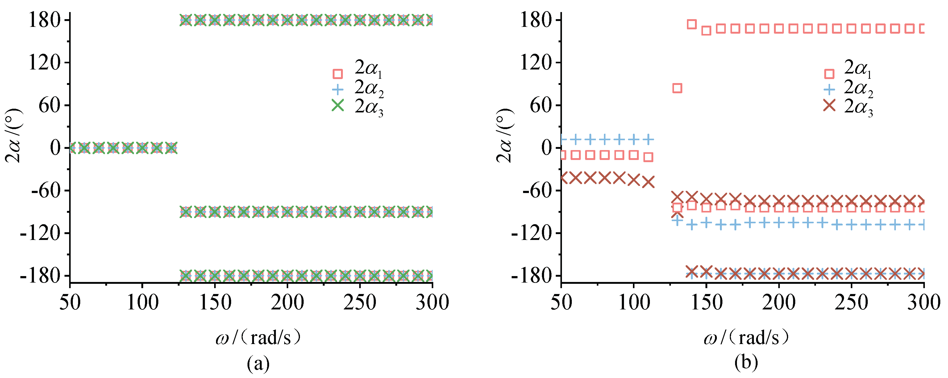
4. Numerical Analysis

The synchronous condition and the stability condition of the system have been studied in Section 3. In this section, the following system parameters are introduced to investigate that the system has several steady-state motions. To simplify the analysis process, k x = k y is chosen. The corresponding parameters are as follows: M = 4370 g , m 0 = 46 g , J = 1750 gm 2 , k x = 70.5 KN / m , k y = 70.5 KN / m and k ψ = 20 KN / m . The natural frequencies are defined as ω x = 127 rad / s , ω y = 127 rad / s , and ω ψ = 107 rad / s .
Equation (8) is used to obtain the phase difference value when the system is stable. Since Equation (8) is a set of transcendental equations, it is not possible to obtain analytic solutions, so bisection method is adopted. Due to the multiple solutions of nonlinear equations, the stability condition of the synchronous state in Equation (13) is used to determine which solution is stable [25]. Applying the parameters in the previous paragraph, phase differences are obtained in Figure 2.
Figure 2a shows the phase differences when the four ERs are identical. When ω 0 127 rad / s , the system is in sub-resonant state. At this stage, the stable phase difference close to 0 ° results in the superposition of the resultant forces of four ER, which makes the vibration body move in a large amplitude circle. When ω 0 > 127 rad / s , the system is in super-resonant state. At another stage, there are two cases of stable phase differences: | 180 ° | and | 90 ° | . These results show that the phase differences have two sets of stable solutions, which means two equilibrium points. Therefore, the system has two synchronous states in super-resonant case.
Because ERs are driven directly by motors, not only the mechanical part will affect the steady-state motion of the vibration system, but the difference of the electrical part will also affect the steady-state motion. To verify vibration synchronization of ERs is an electromechanical coupling process, the different damping torque of the motor is discussed as shown in Figure 2b. The phase differences change correspondingly around 0 ° when system is in sub-resonant state, ω 0 127 rad / s . On the contrary, ω 0 > 127 rad / s , there are still two cases of phase differences around | 180 ° | and | 90 ° | in super-resonant state. The phase difference curves in Figure 2b explain that the electrical part plays a key role in the stable phase difference.
Based on the conclusion in Figure 2, it is found that the system has multiple equilibrium states. To analyze the selective motion characteristics of the system, a force analysis diagram in Figure 3 is used in combination with Figure 2.
Choosing the rotation angles of ERs determined by phase differences in Figure 2a, the force analysis of the rigid body is carried out in Figure 3a when the system is in sub-resonant state, ω 0 127 rad / s . The resultant force of four ERs makes the rigid body move in circular motion, which is consistent with the motion selection principle of the vibration system [20]. The resultant force of ERs is superimposed and the vibration amplitude reaches the maximum value. Hence, the circular motion trajectory can be used to design a kind of vibration screen.
When the system is in super-resonant state, phase differences are | 90 ° | in Figure 3b. Because the resultant forces of four ERs cancel out, the rigid body is at rest, which is in accordance with the principle of minimum potential energy [28]. In another steady-state, phase differences are | 180 ° | as shown in Figure 3c. The resultant forces of four ERs also cancel out as Figure 3b. In the same way, there is no motion on the rigid body.
To sum up, the system chooses vibration as its motion state in the sub-resonant state, whereas it chooses rest as its motion state in the super-resonant state. In particular, the super-resonant has two motion states.

5. Experiment

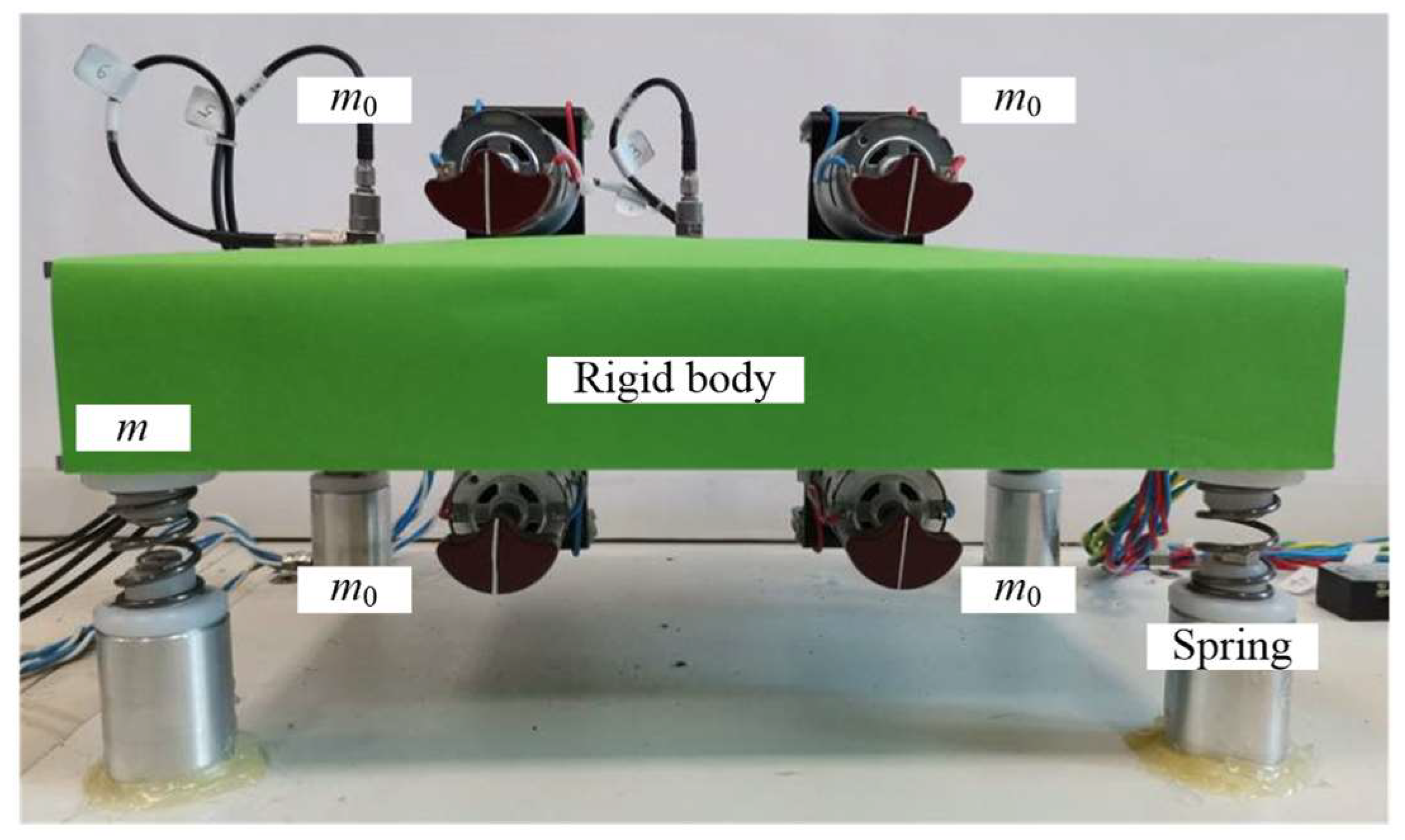
5.1. Experimental Machine

Figure 4 shows experimental machine corresponding to the dynamic model of the system. Four ERs driven by DC motor are symmetrically distributed on the rigid body. In this work, four motors are supplied with the same voltage to investigate vibration synchronization and no motor control scheme is used. Adjusting the voltage of the motor to change the angular velocity of ER, the system can be run in sub-resonant state or super-resonant state. The center and edge of the rigid body are installed with two perpendicular acceleration sensors (type: IEPE, the sensitivity of 20 mv/g), respectively, to measure the acceleration amplitudes of the rigid body in x and y directions. Each ER is installed to a photoelectric sensor (type: NPN, voltage: 5 V) to measure the motor velocity and the phase of the eccentric block. The sensor signal is collected by B&K data equipment (sampling time: 10 kHz). The experimental results with different motion states are shown in Figure 5, Figure 6, Figure 7, Figure 8, Figure 9, Figure 10, Figure 11 and Figure 12. The rotational velocities and phase differences of ERs are obtained by using the pulse interval time of the photoelectric sensor. No signal processing technique is performed on the acceleration amplitude signal. For simplicity, the amplitudes referred to in the following discussion are acceleration amplitudes. The curves are plotted using Origin 9.0.

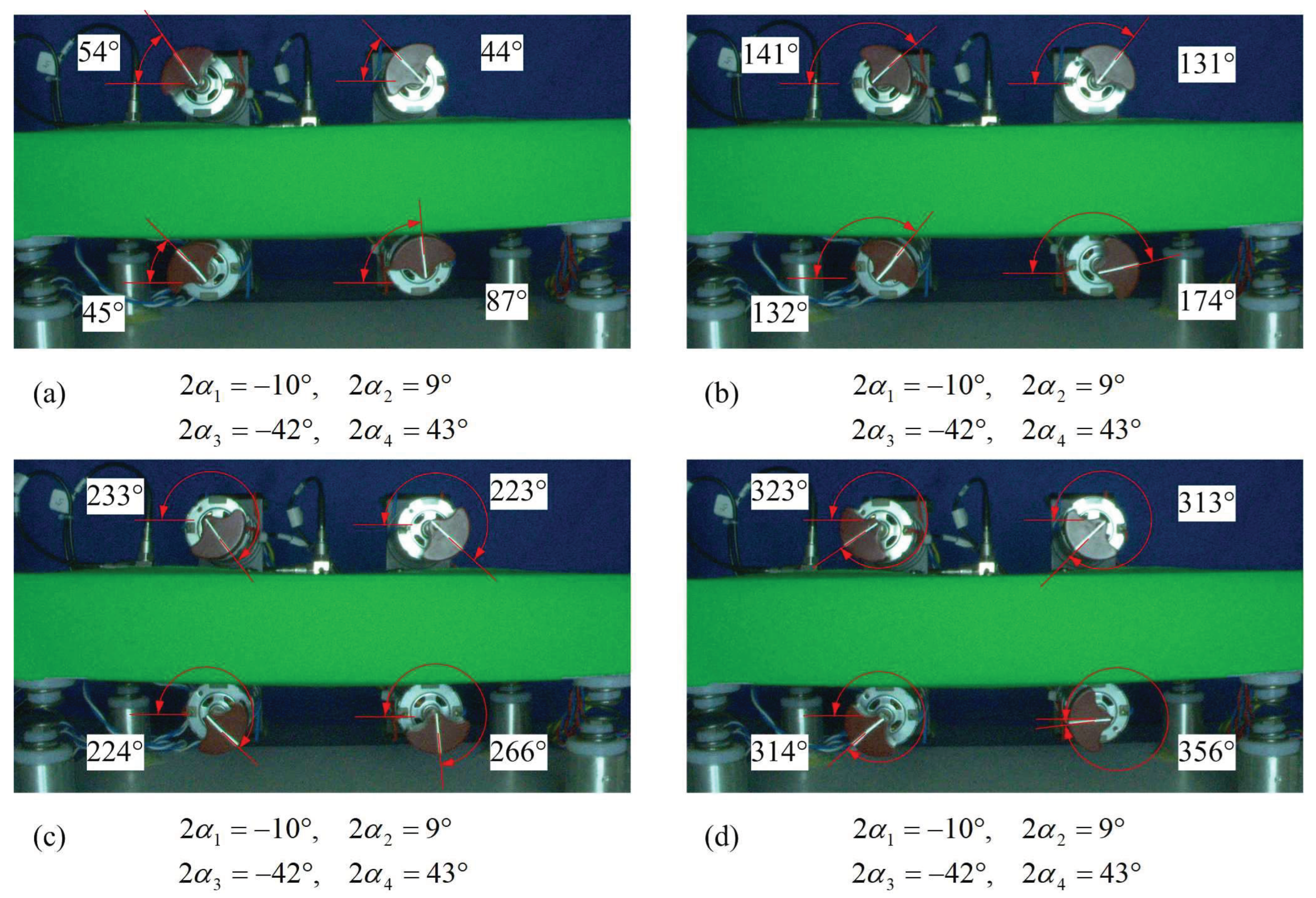
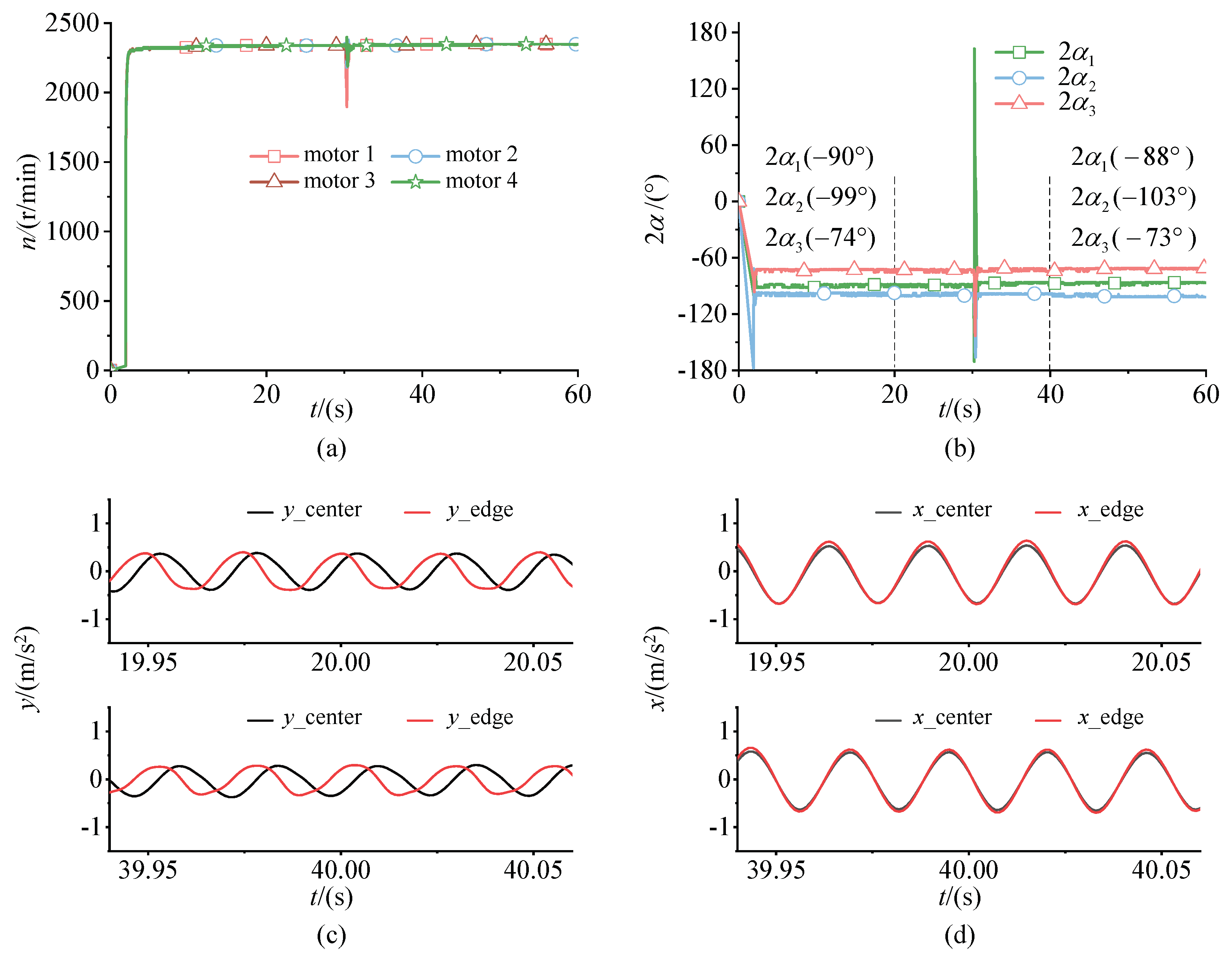
5.2. The System Is in the Sub-Reasonant State

Both time domain curves in Figure 5 and high speed images in Figure 6 are used to study the dynamic characteristics of the system.
Figure 5a shows that the synchronous velocity of ERs is 780 r/min and the corresponding excitation frequency is ω 0 = 82 rad / s . Therefore, the system is in sub-resonant state at this stage. When ERs are supplied with power simultaneously, four ERs quickly perform a steady-state motion because parameters of the system satisfy the synchronous condition. In Figure 5b, the phase differences are 2 α 1 = 10 ° , 2 α 2 = 9 ° , and 2 α 3 = 42 ° when the system runs in synchronous state.
Comparing the acceleration curves in Figure 5c with Figure 5d, the vibration phases of x direction are almost identical between the mass center and the edge at two different times: 20 s and 40 s. However, the vibration phases of y direction have certain differences with those of x direction. There are two reasons: first, the phase differences of ERs are not exactly equal to 0 ° , which make the rigid body swing around the mass center. The sway of the rigid body has more influence on y direction than x direction for the experimental machine in Figure 4. Second, the amplitude in x direction is greater than that in y direction, which is caused by the difference stiffness of the cylindrical spring between x and y direction. In fact, excitation frequency ω 0 = 82   rad / s is more closely related to the natural frequency in x direction. Generally speaking, the motion trajectory of the mass center is a long ellipse whose long axis is x direction.
After 30 s, this disturbance method quickly powering off ER 1 and then powering on ER 1 is adopted to analyze the stability of the system. It can be found that the system quickly recovers to a state similar to that before the disturbance. This is because the vibration amplitude of the rigid body is large, which leads to the coupling torque to be large and strong. To verify the data accuracy from the acquisition equipment, the image method is used for comparison in Figure 6.
During the experiment, a high-speed camera records the instantaneous phases of four ERs at a 50 Hz acquisition frequency. As shown in Figure 6, phase differences obtained by measurement are 2 α 1 = 10 ° , 2 α 2 = 9 ° , and 2 α 3 = 42 ° . This result corresponds well with the data in Figure 5b.

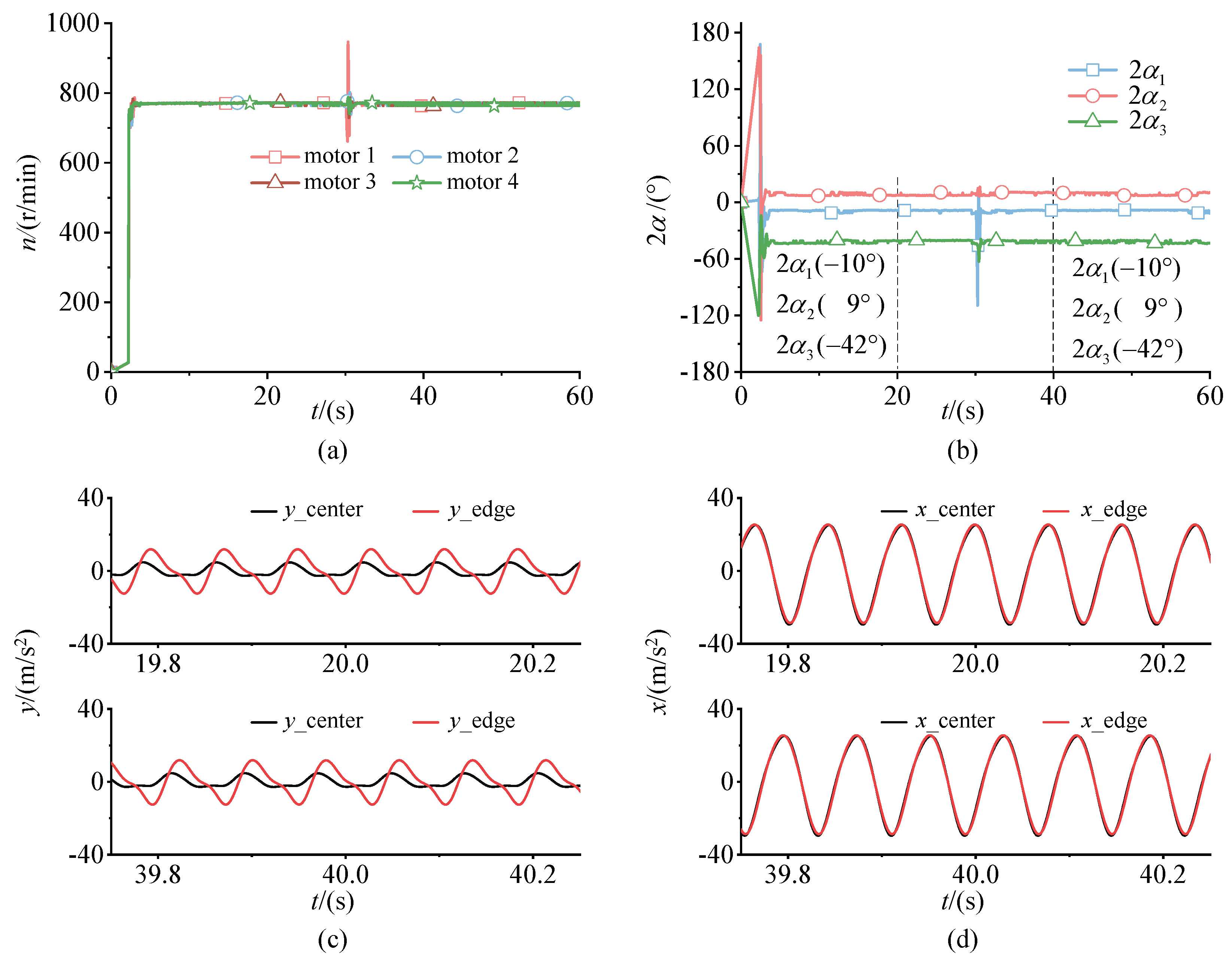
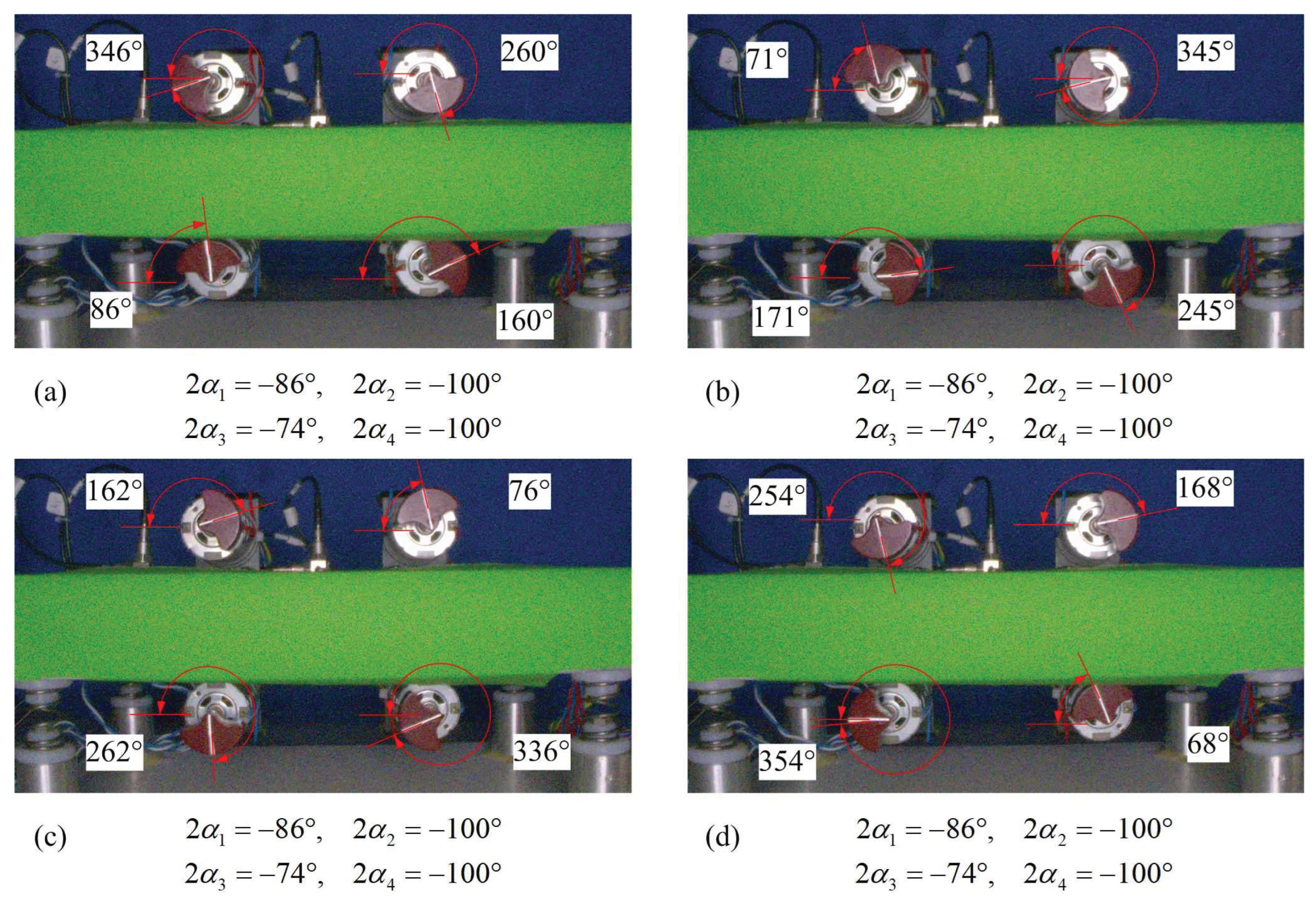
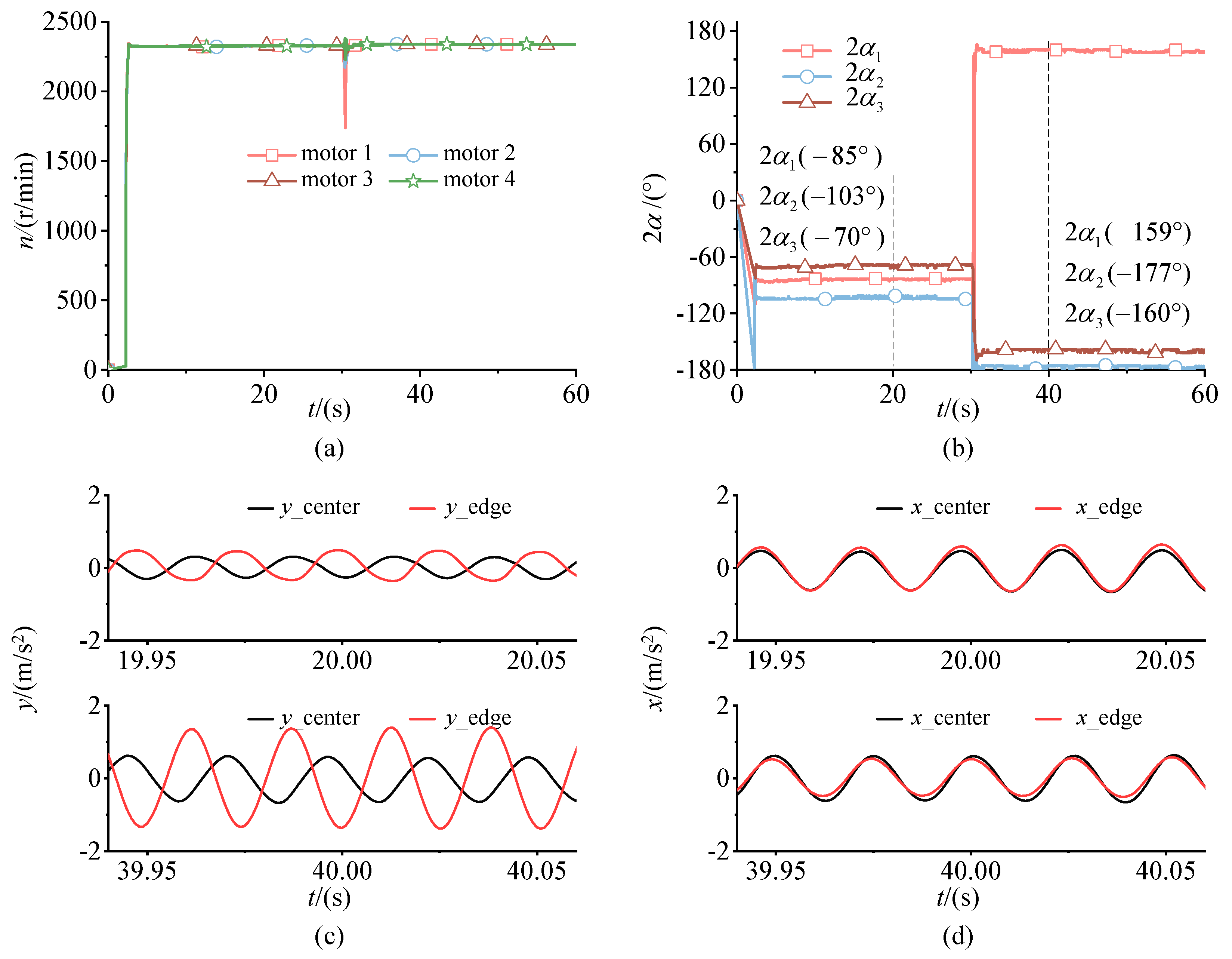
5.3. The System Is in the Super-Resonant State

Adjusting excitation frequency of motor to ω 0   241   rad / s , then system is in super-resonant state. According to Figure 2, there are two sets of steady-state phase differences. Therefore, there are also four sets of changes in super-resonant state, which are analyzed sequentially from Figure 7, Figure 8, Figure 9, Figure 10, Figure 11 and Figure 12.

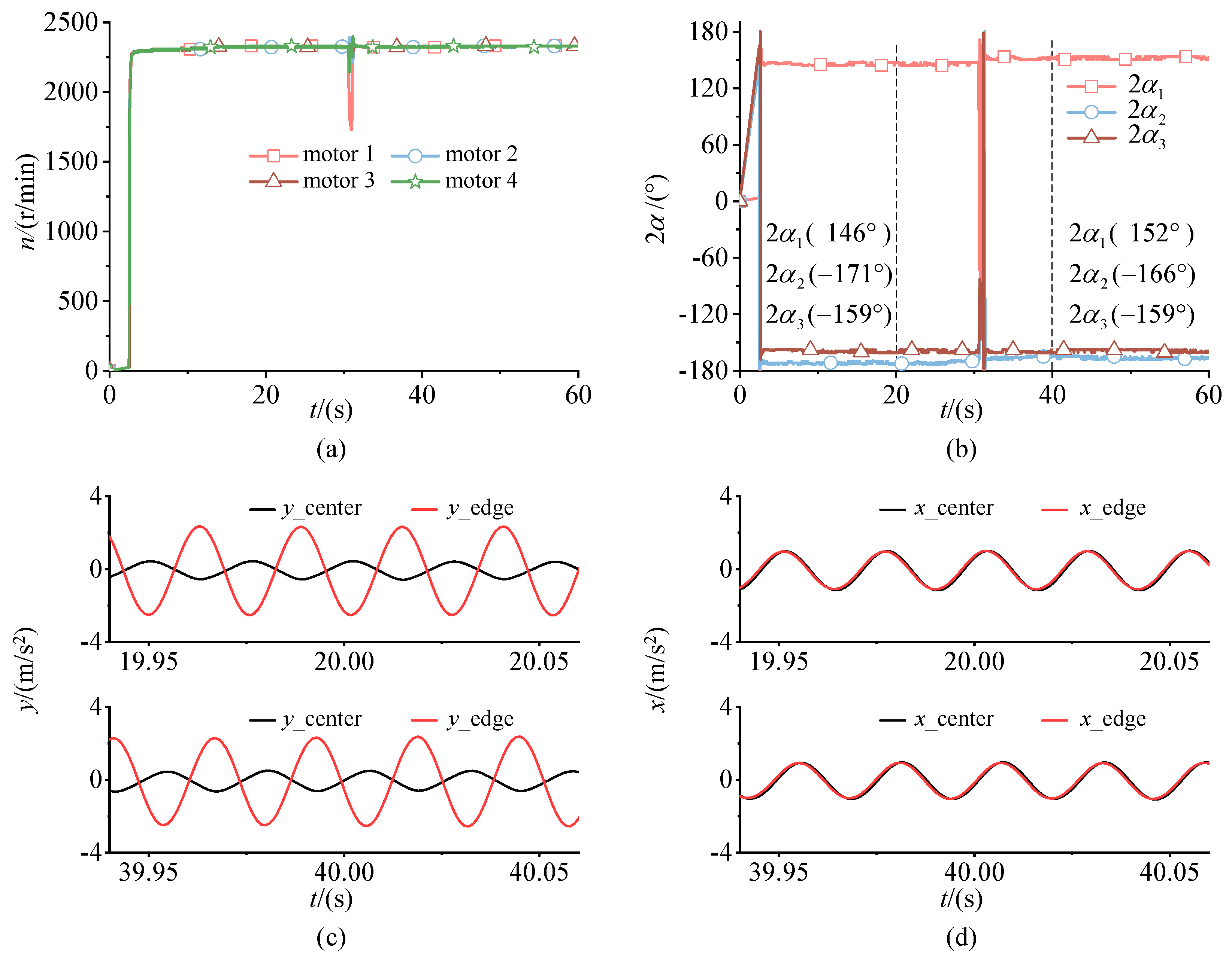
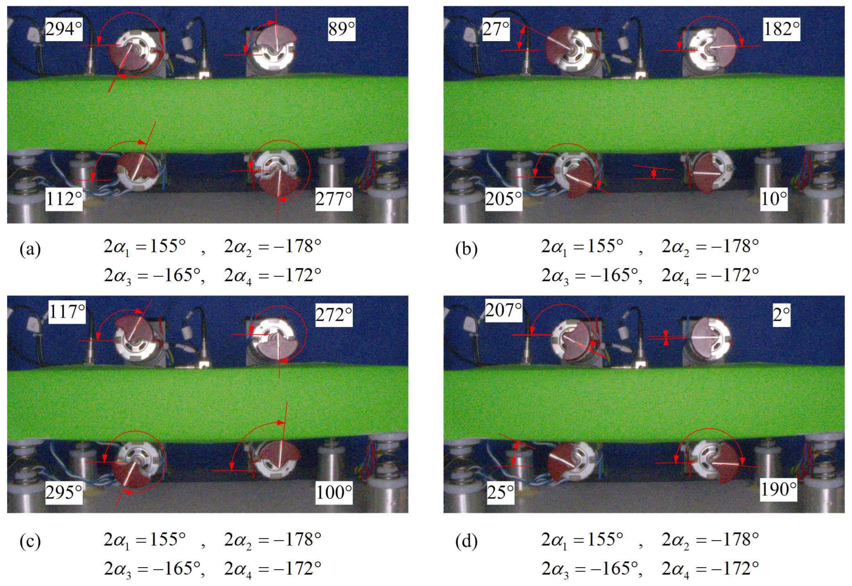
5.3.1. Steady State One

In Figure 7, four ERs quickly run in the synchronous state when ERs are supplied power simultaneously. At 20 s, the synchronous velocity of ERs fluctuate at 2330 r/min, and phase differences are 2 α 1 = 90 ° , 2 α 2 = 99 ° , and 2 α 3 = 74 ° . The disturbance method in Figure 5 is used at 30 s. After the system returns to steady-state motion again, it can be found that the motion state is not changed. At 40 s, the synchronous velocity of ERs fluctuate at 2330 r/min, and phase differences are 2 α 1 = 88 ° , 2 α 2 = 103 ° , and 2 α 3 = 73 ° . Stable phase differences have slight fluctuations at two different moments because of characteristics of small fluctuations when the electromechanical coupling system runs in the state of vibration synchronization.
Comparing the acceleration curves in Figure 7c with Figure 7d, it can be seen that acceleration amplitudes in y direction are not the same phase. Moreover, acceleration amplitudes in x direction are in phase. These motions explain that the motion state of the rigid body is slightly swinging on the mass center. Although curves in Figure 7c,d fluctuates a little bit, it is not that big, which means that forces are mostly cancelling out. Combined with force analysis in Figure 3, the motion state can be well reflected by the phase differences of ERs.
Figure 8 is that phase differences of ERs in super-resonant state are recorded by high-speed camera at 155 Hz. The average values of phase differences are 2 α 1 = 86 ° , 2 α 2 = 100 ° , and 2 α 3 = 74 ° . These results are consistent with those in Figure 7b.

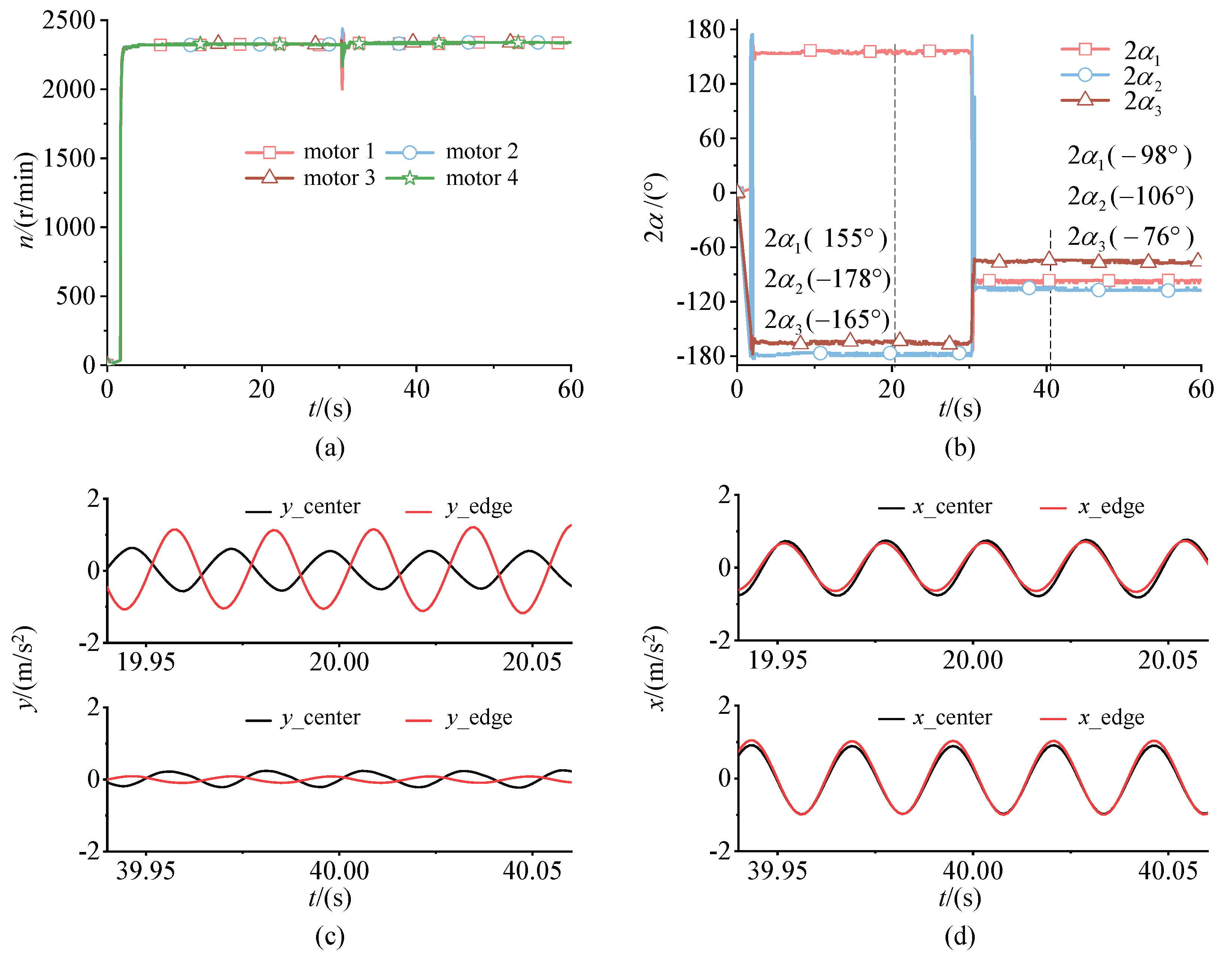
5.3.2. Steady State Two

In Figure 9, the system presents two steady-state motions. At 20 s, the synchronous velocity of ERs fluctuates at 2330 r/min and phase differences are 2 α 1 = 85 ° , 2 α 2 = 103 ° and 2 α 3 = 70 ° . At 40 s, the synchronous velocity of ERs fluctuates at 2320 r/min, which means there’s not much change on the synchronous velocity between 20 s and 40 s. However, the phase difference 2 α 1 changes from 85 ° to 159 ° , the phase difference 2 α 2 from 103 ° to 177 ° , and the phase difference 2 α 3 from 70 ° to 160 ° . The phenomenon illustrates that the system has two motion states in super-resonant stage. This experiment proves that the final motion state of ERs depends on the initial or the disturbed conditions.
From Figure 9c,d, the changes of the acceleration are basically consistent with Figure 7 at 20 s. However, the changes at 40 s are different from those at 20 s. Comparing two different moments, it can be found that magnitudes at 20 s are less than 40 s in x and y directions. Therefore, it can be concluded that the vibration amplitude of the rigid body of the 90 ° phase difference is smaller than that of the 180 ° phase difference. The result also expresses that the offset way of excitation forces of ERs in the 90 ° phase difference is better because the rigid body has a larger swing amplitude when phase differences approach 180 ° .
It is worth noting that the vibration torque T L i of the system at 40 s is larger than that at 20 s, resulting in motor load, which is also large, so the synchronous velocity of ERs will be reduced slightly at 40 s. The phase difference between the two states is not exactly close to 90 ° or 180 ° , which indicates the system is asymmetric. Generally speaking, acceleration phases of y direction are nearly opposite and vibration phases of x direction are almost identically, which follows the principle of minimum potential energy [28].

5.3.3. Steady State Three

In Figure 10, the synchronous velocity of ERs fluctuates at 2320 r/min. At 20 s, phase differences are 2 α 1 = 146 ° , 2 α 2 = 171 ° , and 2 α 3 = 159 ° . At 40 s, the synchronous velocity of ERs fluctuates at 2320 r/min and phase differences are 2 α 1 = 152 ° , 2 α 2 = 166 ° , and 2 α 3 = 159 ° . After the disturbance, stable phase differences have slight changes at two different moments. This is because the synchronous process is an electromechanical coupling process. Since the synchronous motion fluctuates, so does the phase difference. In this work, the time difference of the pulse of the photoelectric sensor is used to calculate the phase difference of ERs. The curves fluctuated due to the algorithm used. In spite of the disturbance, the system still selects the steady-state motion of the 180 ° phase difference. Because the system is asymmetric, the motion state of the rigid body is slightly swinging around the mass center.
Figure 11 is that phase differences of ERs in super-resonant state are recorded by high-speed camera at 155 Hz. The average values of phase differences are 2 α 1 = 155 ° , 2 α 2 = 178 ° , and 2 α 3 = 165 ° . These results are consistent with those in Figure 10b.

5.3.4. Steady State Four

In Figure 12, the system implements another way to change when the disturbance is applied.
The synchronous velocity of ERs fluctuates at 2320 r/min and phase differences are 2 α 1 = 155 ° , 2 α 2 = 178 ° , and 2 α 3 = 165 ° at 20 s. However, phase differences 2 α 1 change from 155 ° to 98 ° , 2 α 2 from 178 ° to 106 ° , and 2 α 3 from 165 ° to 76 ° at 40 s. The synchronous velocity of 40 s fluctuates at 2330 r/min, which has a slight change compared to that of 20 s. Other changes are the same as the previous three experiments.
To sum up, the disturbance method of cutting off power is used to study the selective motion characteristics of the system. It can be found that the system can perform synchronous motion as long as the synchronization condition is available. Further, the experimental results show that the synchronous motion state depends on the initial condition and the disturbance condition. In this vibration machine, the system has five kinds of synchronous states, which shows that the system has selective motion characteristics.

6. Conclusions

This paper takes four co-rotating and circularly distributed ERs to excite a single mass rigid body as research object. The selective motion characteristics of the system are investigated theoretically and experimentally. Conclusions are as follows:
(1) Since the synchronous condition is transcendental equation of the phase differences, not only it has the characteristics of multiple solutions but also it is not possible to obtain an analytical expression. A numerical method is proposed to calculate the phase difference according to the synchronous condition and its stability condition, which is proved by the experiments.
(2) Based on the principle of minimum potential energy, phase differences distribution of four ERs are given according to force analysis, which is verified theoretically and experimentally.
(3) Since vibration synchronization is essentially an electromechanical coupling process, the influence of motor is investigated on the synchronous state. The mechanical part of experimental machine adopts an even number of pairs of ERs symmetrically distributed on the rigid body, and electrical part uses four motors with same specifications. Despite the same type of motor, there are still differences, which can be found from the experimental results.
(4) This kind of vibration system has two synchronous states in super-resonant state and one synchronous state in sub-resonant are proved theoretically and experimentally. Combined with the force analysis, symmetry of the 90 ° phase differences are better than that of 180 ° because the system response of 90 ° is smaller.

Author Contributions

X.C. and L.L. conceived and designed the research. J.L. conducted the theory. J.Z. analyzed the data. X.C. wrote the manuscript. L.L. reviewed and edited the manuscript. All authors reviewed the manuscript. All authors have read and agreed to the published version of the manuscript.

Funding

This research was supported by National Natural Science Foundation of China (Grant No. 51905081), Natural Science Foundation of Hebei Province (Grant No. E2019501117, E2021501014), and the Fundamental Research Funds for the Central Universities (N2223028, N2123026).

Institutional Review Board Statement

Not applicable.

Informed Consent Statement

Not applicable.

Data Availability Statement

Not applicable.

Conflicts of Interest

The authors declare no conflict of interest.

Appendix A

W s = μ x sin γ x + μ y sin γ y + μ ψ r l 2 sin γ ψ ,
a c s i j = μ x sin γ x + μ y sin γ y + μ ψ r l 2 sin γ ψ cos ( β i β j )
b c s i j = μ ψ r l 2 sin γ ψ sin ( β i β j )
a c c i j = μ x cos γ x + μ y cos γ y + μ ψ r l 2 cos γ ψ cos ( β i β j )
b c c i j = μ ψ r l 2 cos γ ψ sin ( β i β j )
W c s i j = r m a c s i j 2 + b c s i j 2 , θ s i j = { arctan ( b c s i j a c s i j ) , a c s i j 0 π + arctan ( b c s i j a c s i j ) , a c s i j < 0
W c c i j = r m a c c i j 2 + b c c i j 2 , θ c i j = { arctan ( b c c i j a c c i j ) , a c c i j 0 π + arctan ( b c c i j a c c i j ) , a c c i j < 0 ,
χ f 1 = 1 2 { W s 1 + W c s 12 cos ( 2 α ¯ 1 + θ s 12 ) + W c s 13 cos ( 2 α ¯ 1 + 2 α ¯ 2 + θ s 13 ) + W c s 14 cos ( 2 α ¯ 1 + 2 α ¯ 2 + 2 α ¯ 3 + θ s 14 ) } ,
χ a 1 = 1 2 { W c c 12 sin ( 2 α ¯ 1 + θ c 12 ) + W c c 13 sin ( 2 α ¯ 1 + 2 α ¯ 2 + θ c 13 ) + W c c 14 sin ( 2 α ¯ 1 + 2 α ¯ 2 + 2 α ¯ 3 + θ c 14 ) } ,
χ f 2 = 1 2 { W s 2 + W c s 12 cos ( 2 α ¯ 1 + θ s 12 ) + W c s 13 cos ( 2 α ¯ 2 + θ s 23 ) + W c s 13 cos ( 2 α ¯ 2 + 2 α ¯ 3 + θ s 24 ) } ,
χ a 2 = 1 2 { W c c 12 sin ( 2 α ¯ 1 + θ c 12 ) + W c c 23 sin ( 2 α ¯ 2 + θ c 23 ) + W c c 24 sin ( 2 α ¯ 2 + 2 α ¯ 3 + θ c 24 ) } ,
χ f 3 = 1 2 { W s 3 + W c s 13 cos ( 2 α ¯ 1 + 2 α ¯ 2 + θ s 13 ) + W c s 23 cos ( 2 α ¯ 2 + θ s 23 ) + W c s 34 cos ( 2 α ¯ 3 + θ s 34 ) } ,
χ a 3 = 1 2 { W c c 13 sin ( 2 α ¯ 1 + 2 α ¯ 2 + θ c 13 ) W c c 23 sin ( 2 α ¯ 2 + θ c 23 ) + W c c 34 sin ( 2 α ¯ 3 + θ c 34 ) } ,
χ f 4 = 1 2 { W s 4 + W c s 14 cos ( 2 α ¯ 1 + 2 α ¯ 2 + 2 α ¯ 3 + θ s 14 ) + W c s 24 cos ( 2 α ¯ 2 + 2 α ¯ 3 + θ s 24 ) + W c s 34 cos ( 2 α ¯ 3 + θ s 34 ) } ,
χ a 4 = 1 2 { W c c 14 sin ( 2 α ¯ 1 + 2 α ¯ 2 + 2 α ¯ 3 + θ c 14 ) W c c 24 sin ( 2 α ¯ 2 + 2 α ¯ 3 + θ c 24 ) W c c 34 sin ( 2 α ¯ 3 + θ c 34 ) } ,
d 11 = W c c 12 cos ( 2 α ¯ 10 + θ c 12 ) / k 2 + W c c 12 cos ( 2 α ¯ 10 + θ c 12 ) / k 1 + W c c 13 cos ( 2 α ¯ 10 + 2 α ¯ 20 + θ c 13 ) / k 1 + W c c 14 cos ( 2 α ¯ 10 + 2 α ¯ 20 + 2 α ¯ 30 + θ c 14 ) / k 1 ,
d 12 = W c c 23 cos ( 2 α ¯ 20 + θ c 23 ) / k 2 + W c c 24 cos ( 2 α ¯ 20 + 2 α ¯ 30 + θ c 24 ) / k 2 W c c 13 cos ( 2 α ¯ 10 + 2 α ¯ 20 + θ c 13 ) / k 1 W c c 14 cos ( 2 α ¯ 10 + 2 α ¯ 20 + 2 α ¯ 30 + θ c 14 ) / k 1 ,
d 13 = W c c 24 cos ( 2 α ¯ 20 + 2 α ¯ 30 + θ c 24 ) / k 2 W c c 14 cos ( 2 α ¯ 10 + 2 α ¯ 20 + 2 α ¯ 30 + θ c 14 ) / k 1 ,
d 21 = W c c 12 cos ( 2 α ¯ 10 + θ c 12 ) / k 2 W c c 13 cos ( 2 α ¯ 10 + 2 α ¯ 20 + θ c 13 ) / k 3 ,
d 22 = W c c 23 cos ( 2 α ¯ 20 + θ c 23 ) / k 2 + W c c 24 cos ( 2 α ¯ 20 + 2 α ¯ 30 + θ c 24 ) / k 2 + W c c 13 cos ( 2 α ¯ 10 + 2 α ¯ 20 + θ c 13 ) / k 3 + W c c 23 cos ( 2 α ¯ 20 + θ c 14 ) / k 3 ,
d 23 = W c c 34 cos ( 2 α ¯ 30 + θ c 34 ) / k 3 W c c 24 cos ( 2 α ¯ 20 + 2 α ¯ 30 + θ c 24 ) / k 2 ,
d 31 = W c c 13 cos ( 2 α ¯ 10 + 2 α ¯ 20 + θ c 13 ) / k 3 W c c 14 cos ( 2 α ¯ 10 + 2 α ¯ 20 + 2 α ¯ 30 + θ c 14 ) / k 4 ,
d 32 = W c c 13 cos ( 2 α ¯ 10 + 2 α ¯ 20 + θ c 13 ) / k 3 + W c c 23 cos ( 2 α ¯ 20 + θ c 23 ) / k 3 + W c c 14 cos ( 2 α ¯ 10 + 2 α ¯ 20 + 2 α ¯ 30 + θ c 14 ) / k 4 + W c c 24 cos ( 2 α ¯ 20 + 2 α ¯ 30 + θ c 14 ) / k 4 ,
d 33 = W c c 34 cos ( 2 α ¯ 30 + θ c 34 ) / k 3 + W c c 14 cos ( 2 α ¯ 10 + 2 α ¯ 20 + 2 α ¯ 30 + θ c 14 ) / k 4 + W c c 24 cos ( 2 α ¯ 20 + 2 α ¯ 30 + θ c 24 ) / k 4 + W c c 14 cos ( 2 α ¯ 30 + θ c 34 ) / k 4 ,

References

  1. Blekhman, I.I.; Fradkov, A.L.; Tomchina, O.P.; Bogdanov, D.E. Self-synchronization and controlled synchronization: General definition and example design. Math. Comput. Simul. 2002, 58, 367–384. [Google Scholar] [CrossRef]
  2. Blekhman, I.I.; Sorokin, V.S. On the separation of fast and slow motions in mechanical systems with high-frequency modulation of the dissipation coefficient. J. Sound Vib. 2010, 329, 4936–4949. [Google Scholar] [CrossRef]
  3. Czolczynski, K.; Okolewski, A.; Blazejczyk-Okolewska, B. Lyapunov exponents in discrete modelling of a cantilever beam impacting on a moving base. Int. J. Non-Linear Mech. 2017, 88, 74–84. [Google Scholar] [CrossRef]
  4. Dudkowski, D.; Czolczynski, K.; Kapitaniak, T. Multistability and synchronization: The co-existence of synchronous patterns in coupled pendula. Mech. Syst. Signal Process. 2022, 166, 108446. [Google Scholar] [CrossRef]
  5. Kibirktis, E.; Pauliukaitis, D.; Miliunas, V.; Ragulskis, K. Synchronization of pneumatic vibroexciters operating on air cushion with feeding pulsatile pressure under autovibration regime. J. Mech. Sci. Technol. 2018, 32, 81–89. [Google Scholar] [CrossRef]
  6. Miklos, A.; Szabo, Z. Simulation and experimental validation of the dynamical model of a dual-rotor vibrotactor. J. Sound Vib. 2015, 334, 98–107. [Google Scholar] [CrossRef] [Green Version]
  7. Gu, D.; Zhang, X.; Zhang, J.; Liu, Y.; Wen, B. Synchronization and coupling dynamic characteristics of an exciter and two cylindrical rollers in a vibrating system. J. Sound Vib. 2019, 456, 353–373. [Google Scholar] [CrossRef]
  8. Chen, X.; Kong, X.; Dou, J.; Liu, Y.; Wen, B. Numerical and experimental investigation on self-synchronization of two eccentric rotors in the vibration system. J. Vibroeng. 2016, 18, 744–758. [Google Scholar]
  9. Chen, X.; Kong, X.; Zhang, X.; Li, L.; Wen, B. On the Synchronization of Two Eccentric Rotors with Common Rotational Axis: Theory and Experiment. Shock Vib. 2016, 2016, 6973597. [Google Scholar] [CrossRef] [Green Version]
  10. Zou, M.; Fang, P.; Hou, Y.; Peng, H. Investigation on multiple-frequency synchronization experiment of vibration system with dual-rotor actuation. Mech. Syst. Signal Process. 2022, 164, 108261. [Google Scholar] [CrossRef]
  11. Li, L.; Chen, X. Times-frequency synchronization of two exciters with the opposite rotating directions in a vibration system. J. Sound Vib. 2019, 443, 591–604. [Google Scholar] [CrossRef]
  12. Zhao, C.; Zhu, H.; Zhang, Y.; Wen, B. Synchronization of two coupled exciters in a vibrating system of spatial motion. Acta Mech. Sin. 2010, 26, 477–493. [Google Scholar] [CrossRef]
  13. Fang, P.; Zou, M.; Peng, H.; Du, M.; Hu, G.; Hou, Y. Spatial synhronization of unbalanced rotors excited with paralleled and counterrotating motors in s far resonance system. J. Theor. Appl. Mech. 2019, 57, 723–738. [Google Scholar] [CrossRef]
  14. Chen, B.; Xia, X.O.; Wang, X. Synchronization and vibratory synchronization transmission of a weakly damped far-resonance vibrating system. PLoS ONE 2019, 14, e0209703. [Google Scholar] [CrossRef] [PubMed]
  15. Shishkin, E.V.; Kazakov, S.V. Application of vibratory-percussion crusher for disintegration of supertough materials. IOP Conf. Ser.-Earth Environ. Sci. 2017, 87, 022018. [Google Scholar] [CrossRef] [Green Version]
  16. Djanan, A.A.N.; Nbendjo, B.R.N.; Woafo, P. Self-synchronization of two motors on a rectangular plate and reduction of vibration. J. Vib. Control 2015, 21, 2114–2123. [Google Scholar] [CrossRef]
  17. Li, Y.; Li, H.; Wei, X.; Wen, B. Self-synchronization theory of a nonlinear vibration system driven by two exciters. Part 1: Theoretical analysis. J. Vibroeng. 2014, 16, 725–734. [Google Scholar]
  18. Zhang, X.; Wen, B.; Zhao, C. Theoretical, numerical and experimental study on synchronization of three identical exciters in a vibrating system. Chin. J. Mech. Eng. 2013, 26, 746–757. [Google Scholar] [CrossRef]
  19. Chen, X.; Li, L. Phase Synchronization Control of Two Eccentric Rotors in the Vibration System with Asymmetric Structure Using Discrete-Time Sliding Mode Control. Shock Vib. 2019, 2019. [Google Scholar] [CrossRef]
  20. Chen, X.; Li, L. Selected synchronous state of the vibration system driven by three homodromy eccentric rotors. J. Low Freq. Noise Vib. Act. Control 2020, 39, 352–367. [Google Scholar] [CrossRef] [Green Version]
  21. Fang, P.; Wang, Y.; Hou, Y.; Wu, Y. Synchronous Control of Multi-Motor Coupled with Pendulum in a Vibration System. IEEE Access 2020, 8, 51964–51975. [Google Scholar] [CrossRef]
  22. Chen, X.; Liu, J.; Li, L. Dynamics of the Vibration System Driven by Three Homodromy Eccentric Rotors Using Control Synchronization. Appl. Sci. 2021, 11, 7691. [Google Scholar] [CrossRef]
  23. Jia, L.; Zhang, J.; Zhou, L.; Wen, B. Multifrequency-controlled synchronization of three eccentric rotors driven by induction motors in the same direction. J. Low Freq. Noise Vib. Act. Control 2019, 38, 615–632. [Google Scholar] [CrossRef] [Green Version]
  24. Liu, L.; Liu, T.; Yue, H.; Zhang, X. Coupling synchronization principle of two pairs counter-rotating unbalanced rotors in the different resonant conditions. J. Low Freq. Noise Vib. Act. Control 2021, 40, 1149–1165. [Google Scholar] [CrossRef]
  25. Zhang, X.; Li, C.; Wang, Z.; Cui, S. Synchronous Stability of Four Homodromy Vibrators in a Vibrating System with Double Resonant Types. Shock Vib. 2018, 2018, 9641231. [Google Scholar] [CrossRef]
  26. Kong, X.; Wen, B. Composite synchronization of a four eccentric rotors driven vibration system with a mass-spring rigid base. J. Sound Vib. 2018, 427, 63–81. [Google Scholar] [CrossRef]
  27. Zhao, C.; Zhu, H.; Wang, R.; Wen, B. Synchronization of two non-identical coupled exciters in a non-resonant vibrating system of linear motion. Part I: Theoretical analysis. Shock Vib. 2009, 16, 505–515. [Google Scholar] [CrossRef]
  28. Blekhman, I.I. Selected Topics in Vibrational Mechanics; World Scientific: Singapore, 2004; pp. 179–251. [Google Scholar]
Figure 1. The vibration machine is excited by four ERs: (a) Dynamic model of the vibration system; (b) Three reference coordinate systems.
Machines 10 00457 g001
Figure 2. Stable phase differences: (a) Identical motor parameters; (b) Different motor damping.
Machines 10 00457 g002
Figure 3. Force analysis of the system in steady-state motion: (a) Sub-resonant phase differences are 0 ° ; (b) Super-resonant phase differences are | 90 ° | ; (c) Super-resonant phase differences are | 180 ° | .
Machines 10 00457 g003
Figure 4. Experimental machine.
Machines 10 00457 g004
Figure 5. Phase differences of ERs change from 0 ° to 0 ° with disturbance: (a) Synchronous velocities of four ERs; (b) Phase differences; (c) Acceleration amplitude in y direction at 20 s and 40 s; (d) Acceleration amplitude in x direction at 20 s and 40 s.
Machines 10 00457 g005
Figure 6. Phase images of four ERs in sub-resonant state during one period of motion.
Machines 10 00457 g006
Figure 7. Phase differences of ERs change from 90 ° to 90 ° with disturbance: (a) Synchronous velocities of four ERs; (b) Phase differences; (c) Acceleration amplitude in y direction at 20 s and 40 s; (d) Acceleration amplitude in x direction at 20 s and 40 s.
Machines 10 00457 g007
Figure 8. Phase images of 90 ° in super-resonance during one period of motion.
Machines 10 00457 g008
Figure 9. Phase differences of ERs change from 90 ° to 180 ° with disturbance: (a) Synchronous velocities of four ERs; (b) Phase differences; (c) Acceleration amplitude in y direction at 20 s and 40 s; (d) Acceleration amplitude in x direction at 20 s and 40 s.
Machines 10 00457 g009
Figure 10. Phase differences of ERs change from 180 ° to 180 ° with disturbance: (a) Synchronous velocities of four ERs; (b) Phase differences; (c) Acceleration amplitude in y direction at 20 s and 40 s; (d) Acceleration amplitude in x direction at 20 s and 40 s.
Machines 10 00457 g010
Figure 11. Phase images of 180 ° in super-resonance during one period of motion.
Machines 10 00457 g011
Figure 12. Phase differences of ERs change from 180 ° to 90 ° with disturbance: (a) Synchronous velocities of four ERs; (b) Phase differences; (c) Acceleration amplitude in y direction at 20 s and 40 s; (d) Acceleration amplitude in x direction at 20 s and 40 s.
Machines 10 00457 g012
Publisher’s Note: MDPI stays neutral with regard to jurisdictional claims in published maps and institutional affiliations.

