1. Introduction
During the design of industrial machines, the objective and performance are often strictly defined [
1]. In order to achieve optimal machine performance, process rates and load cases need to be kept tightly within that design range. Within those set boundaries, alterations to the process are usually difficult. Because industrial applications show a trend towards more customization [
2], there is a need for more flexible drivetrain solutions. Flexibility means that such drivetrain solutions should enable the easy creation of different power or speed variants without the need to design a new motor each time.
Modularity seems a promising solution to handle the request for flexibility and to combat the constraints in traditional machine design [
3,
4]. While the design process could benefit from a modular approach, modularity impacts drivetrain performance.
Torsional vibrations are important factors in many mechatronic processes, impacting machine performance [
5], and therefore design. The influence of torsional vibrations on the lifetime, cost, and performance of a drivetrain has been demonstrated in [
6,
7]. When using a modular setup, the behaviour of the system towards torsional vibrations is affected by this design. In [
8], the negative effects of cascaded motors regarding torsional oscillations was explored. Through the use of a soft start mechanism, oscillations during start-up were suppressed. This paper investigates the effect on torsional vibrations of switching to a modular drivetrain.
1.1. Modularity
A modular drivetrain is often defined as a configuration of individual mechatronic function modules, where each part of the mechatronic application is expressed as a module. Power electronics, electrical machines, and mechanical systems are in this case seen as individual modules [
1,
9]. The overall drivetrain consists of a combination of several modules, as proposed by [
4,
10]. The use of this definition of modularity has already been widely implemented in many industrial applications, including weaving looms [
11], crane applications [
12], electric vehicles [
13,
14,
15], and power electronics [
16].
In these examples of modularity, the mechatronic system is built as a combination of several unique modules. However, [
17] introduced the concept of defining an identical modular module that is repeated several times to form the drivetrain. The module consists of an electric motor, a power electronic converter to control the motor, and part of the mechanical drivetrain, which can interact with other modules and/or the load application. For larger load cases, several modules can be coupled to create the desired sizing of the drivetrain. The benefits of using this modular approach were researched by [
18], and promising results regarding motion dynamics and tolerance to failures were found.
1.2. Torsional Vibrations
Torsional vibrations can have negative consequences on drivetrain performance. Efforts to mitigate these vibrations can be realized through either passive or active means [
19]. Passive approaches use the inertial and/or damping properties of the drivetrain to dissipate the vibrations. This includes introducing series elasticity [
20], viscous damping [
21], flywheels [
22], or centrifugal pendulum absorbers [
23] in the drivetrain. Passive methods can, however, lead to increased energy consumption [
7], reduce the system dynamics, or only work within a narrow frequency range [
24].
Active methods, on the other hand, try to weaken the undesired vibrations through controller strategies. Control methods are usually based on state feedback or adaptive filters [
25,
26]. An active magnetic bearing was used in [
27] to reduce vibrations with overhung rotors. In many cases, however, torsional displacement is not easily measured in the drivetrain. Torque sensors are expensive, and not easily mounted in a transmission. In [
28], model-based estimators were used as a virtual sensor. Active vibration damping methods have already been implemented in hybrid electric powertrains [
19] and electric vehicles [
29,
30]. The above-mentioned techniques, however, always consider a single source of vibrations, and therefore are not readily applicable in the modular approach.
In the modular drivetrain design, multiple identical motors are used. As electromechanical actuators are a source of torque ripple [
31,
32,
33], the modular approach requires attention to torsional vibrations. Efforts to mitigate the resulting torsional vibrations in a modular drivetrain are investigated here. In [
34], interleaving was proposed to reduce torque ripple in a multiphase motor. In this paper, the interleaving strategy is implemented to reduce torque ripple across several cascaded actuators in a modular drivetrain.
A use case for the modular design approach where torsional vibrations are of importance can be found in applications where a long shaft is used for power transfer, for example, a weaving loom. The driveshaft of a weaving loom is driven by one or more motors [
11]. A common issue with these machines is torsional vibration across the shaft, resulting in desynchronization of the weaving process; [
35,
36] studied the shaft’s torsional dynamics regarding the shaft penetration factor and transient stability, while [
37,
38] have proposed reducing the vibrations across a shaft by modeling a predictive control and adjustable speed control. However, this research involves a single input–single output drivetrain, and thus is not directly applicable to a modular drivetrain. Synchronization of actuators was explored in [
39,
40], although focusing on speed and angular position synchronization, not on the induced torque ripple. Another use case for a modular approach is electric vehicles. While multi-motor drive systems have already been used in this context, the focus in the literature to date has mainly been on torque distribution [
41] and energy management optimization [
42].
1.3. Outline of This Paper
The aim of this article is, first, to investigate the impact of using a modular design on the torsional vibrations in the drivetrain, and second, to mitigate these vibrations using an interleaving strategy of the PWM signals. Weaving looms and electric vehicles have been introduced as excellent examples that could benefit from a modular approach; however, they are complicated drivetrains with many factors that influence the behaviour of the application. In order to demonstrate the use of modularity and the effect on torsional vibrations, a simplified drivetrain is presented. In
Section 2, the mechanical modular drivetrain used in our research is explained.
Section 3 elaborates on the motor model and shows simulation results regarding the performance with respect to the torsional vibrations of the modular drivetrain. The interleaving control strategy used to mitigate the assessed negative impact of using a modular drivetrain is explained in
Section 4. In order to support the claimed simulation results, the results of validation measurements are provided in
Section 5.
Section 6 discusses the presented simulations and measurements, and
Section 7 concludes with an overview of the findings.
2. Mechanical Driveline
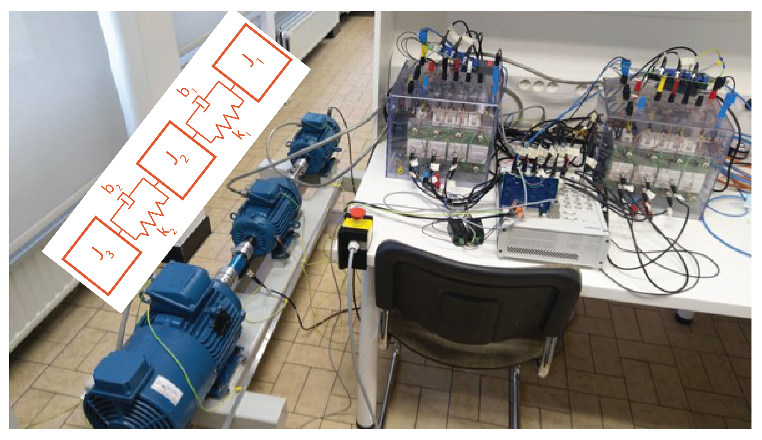
Modularity was previously defined as a system that consists of modules that are repeated several times. In this case, the module, or component block, is composed of an electrical and a mechanical element. The electrical part consists of an asynchronous motor with a speed and current cascade controller and power electronic inverter to generate the PWM signals for motor control. The mechanical element is a shaft interconnected with couplings to link the modules together. The mechanical driveline, illustrated in
Figure 1, is created with two modular modules and a load. A third induction motor is used to generate the load torque. The inertia of the motor represents the load inertia. The modelling was carried out in Matlab/Simscape.
J,
k,
b represent the component’s inertia, stiffness and damping, respectively; the subscripts
,
L,
, and
indicate the used component, i.e., the motor, load, coupling, or shaft, respectively;
T shows the torque; and
shows the position of the motors and load.
2.1. Dynamic Model
The dynamic behaviour of the mechanical components of the driveline was modelled by taking the inertia, stiffness, and damping of each element into account. The component flexibilities were implemented for each coupling and shaft as a two inertia–spring–damper system. This method was chosen over more complex methods such as FEM because it provides an adequate representation and reduces calculation effort. The motor shaft inertias were modelled as well. The torsional flexibility of the motor shaft is not taken into account here, as torsional displacement is not expected at the motor shaft.
The model proposed in
Figure 1 results in a seven inertia system. While describing such a model is possible, it unnecessarily increases calculation time. Because the goal was to model the modular drivetrain, each module was simplified to an inertia–spring–damper system. The model can thus be rewritten as a three-inertia system, two modules, and a load, as illustrated in
Figure 2. This simplification was carried out according to (
1), and the approach is further validated in
Section 2.2, where it is shown that the drivetrain indeed acts as a three-inertia system.
The simplified 3DOF (degrees of freedom) model can then be described with the equations of motion (
2), similar to the 2DOF model presented by [
43]. It is important to note that this model assumes linear system behaviour. High torsion amplitudes and torsion moments, where the behaviour becomes non-linear, are not taken into account.
The eigenvalues
, and
can be calculated with the free vibration system of (
2) according to (
3) [
44]:
J,
K, and the inertia and stiffness matrices are described in (
4), and
is an identity matrix.
From the eigenvalues, the undamped natural frequencies (
and
) of the system can be found with (
5). For this system, the undamped natural frequencies, calculated with the values from
Table 1, are found at 0, 74, and 161 Hz:
In order to use the dynamical model, the parameters from (
1) must be specified. Inertia and stiffness values are easily calculated or found in datasheet information. The damping parameters can be calculated according to (
6). However, implementing the correct damping ratio (
) is difficult. Therefore, in order to properly implement damping into the dynamical behaviour of the mechanical model, a test setup was used to identify the parameters of the dynamic system through frequency response analysis, converting (
2) to a transfer function model. After Laplace transformation and implementing Cramer’s rule, the relations between torques and angular speeds are provided in (
7), with
s the complex variable in the complex frequency domain. The transfer functions (
) are described in
Appendix A Equation (
A1):
2.2. Dynamical Behaviour Validation
To obtain proper damping characteristics, frequency response measurements were performed with the setup shown in
Figure 3, built up in the same manner as the schematic model from
Figure 1. The first module has a steel shaft with a diameter of 18 mm and a length of 108 mm. The second module uses a torque sensor (Lorenz DR-2112) as a shaft. All components are connected with backlash-free servo couplings (KTR Radex-NC). The motor in the first module is equipped with an encoder to measure angular position.
The system transfer function, represented by a Bode plot, was identified using the Matlab Signal processing toolbox. A random uniformly-distributed torque signal at motor M1 was used as the input signal, while the encoder speed was used as the output. This makes it possible to estimate the system transfer function,
, in (
7). During this measurement, motor M2 and the load motor are not energized, and remain connected. In this way, the mechanical system stays identical. Performing this experiment to identify one transfer function provides enough information to estimate all functions. While different excitations propagate differently, the identification is unchanged.
A random torque signal with a magnitude of 20% of the nominal motor torque was applied on motor M1 through field-oriented control. A uniformly distributed random offset of ±3.5% was used. A 1 ms sampling time was used. By fitting the damping ratio,
, in (
6), the damping behaviour of the model can be closely matched to the real setup. Small alterations to the parameters found in the component datasheets were made to fine-tune the model further. The final model parameters used after fitting are listed in
Table 1.
In
Figure 4, the Bode plots from physical measurement and the theoretical model are compared with each other. It is clear that the measured and estimated transfer functions have a similar characterization, with the system resonance modes at 74 and 161 Hz. Note that the measured frequencies above 200 Hz show high oscillations. This is caused by the limitations of the measurement method, and does not properly represent the actual behaviour.
3. Motor Control
To model the asynchronous motors, we used an available motor model according to (
8) in Matlab/Simscape Electrical [
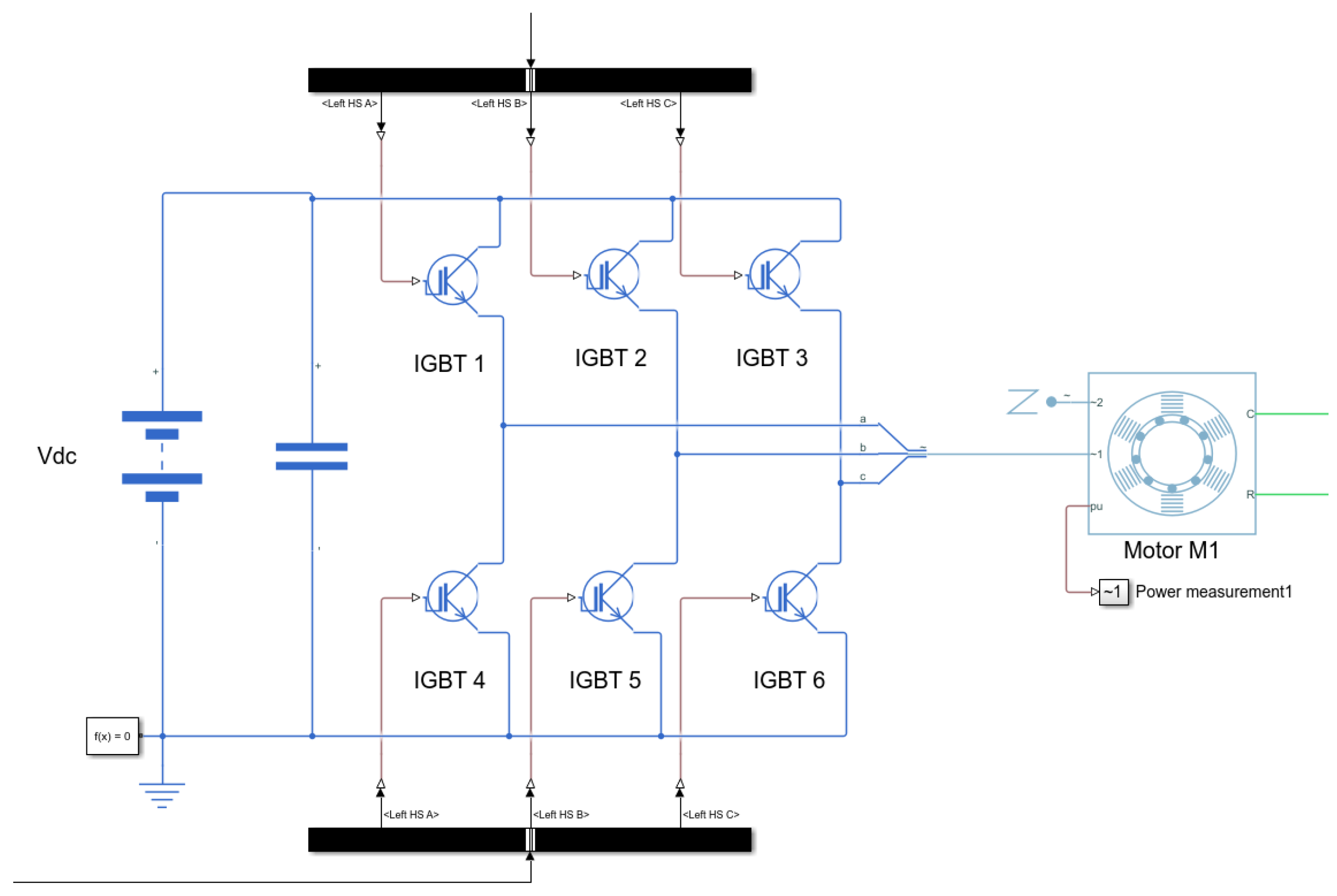
45]. The standard two level inverter was modelled as depicted in
Figure 5. The inverter had a switching frequency of 4 kHz. A field-oriented control was used for each motor. Current control was individual for each module. A PI cascade controller was used for speed regulation. Both modules share the same speed feedback from the encoder positioned at motor M1, as shown in
Figure 3.
With
,
, and
the d-axis, q-axis, and zero-sequence stator voltages,
and
the d-axis and q-axis rotor voltages,
,
, and
the d-axis, q-axis and zero-sequence stator flux linkages,
and
the d-axis and q-axis rotor flux linkages,
,
, and
the d-axis, q-axis, and zero-sequence stator currents,
and
the d-axis and q-axis rotor currents,
and
the stator and rotor resistance,
and
the stator and rotor inductances,
the magnetizing inductance, and
T the rotor torque. An overview of the parameters can be found in
Table 2.
The motor model does not take any efficiency losses or slot harmonics into account. However, a power electronic inverter with sinusoidal PWM introduces an electromagnetic torque ripple that causes an exciting force on the mechanical drivetrain.
To showcase this, simulations with the model were carried out. Steady state behaviour at a constant speed of 500 rpm was studied. A 5 Nm load was set at the load motor. In the modular scenario, both motors M1 and M2 are used and share the load. In
Figure 6, the frequency spectrum of the torque input from motor M2 during the modular scenario is shown. A torque ripple at the PWM switching frequency of 4 kHz is visible. An excitation of the first mechanical resonance, at 74 Hz, is visible as well. For motor M1, similar behaviour is observed.
To evaluate the performance of the modular setup, a benchmark scenario was chosen. Here, only motor M1 is energized and carries the load. Motor M2 remains mechanically connected in order to maintain the same mechanical drivetrain, and is not used. In
Figure 7a the torque at the load during the benchmark is shown. The high-frequency torque ripple at 4 kHz is dampened by the mechanical system, and only a vibration at the resonance frequency remains. The torque ripple has an amplitude of 0.24 Nm. When observing the same signal during the modular scenario, as depicted in
Figure 7b, the ripple increases by 91% to 0.46 Nm. Furthermore, a harmonic of the resonance frequency (2·
) emerges. It can thus be concluded that the use of a modular setup has a negative effect on the torsional vibration behaviour of the drivetrain. An effort to reduce this torque ripple is necessary in order to keep the modular drivetrain design competitive with traditional machine performance.
4. Interleaving for Mechanical Resonance Reduction
The proposed technique to mitigate the negative impact on the electromagnetic torque produced by the current ripple due to the PWM modulation involves interleaving of the PWM carrier waveforms in the different motor modules. Interleaving has previously been used to control the torque ripple at the PWM frequency of a multiphase motor in [
33,
34]; by taking a two-segmented motor system and implementing a phase-shift in the PWM generation of one of the segments, the torque ripple was reduced. The impact on the driven mechanics was not analysed.
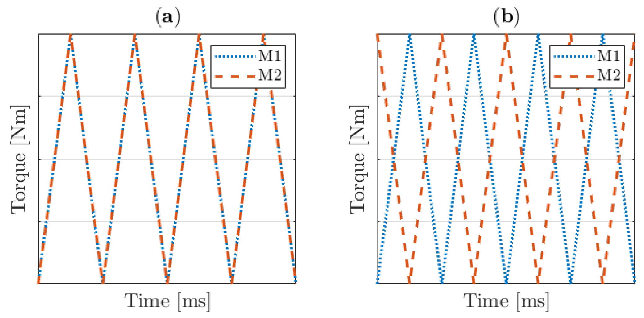
In the present paper, however, two standard three-phase induction motors were used. A phase-shift between the PWM generation of both motors is proposed, as shown in
Figure 8. The torque ripple of each motor is thus not altered, and the impact on the mechanical system level can be investigated. The idea here was to delay the PWM carrier of motor M2 relative to motor M1, thereby offsetting the torque oscillation with respect to motor M1 and bringing both ripples into counter-phase.
4.1. Theoretical Impact of Interleaving on Mechanical Resonances
To investigate the functionality of interleaving, a transfer function model of the mechanical drivetrain was created according to (
9) in order to describe the relationship between the input torques of the motors and the output torque at the load. The model consisted of two transfer functions;
describes the behaviour of a torque input at motor M1 to the load output, while
describes the same for a torque input at motor M2. For a linear system, adding both outputs provides the total torque output of the system. The Bode characteristics of both transfer functions are shown in
Figure 9; the transfer functions are described in
Appendix A Equation (
A3).
The goal of using an interleaving strategy is to impact the behaviour at the mechanical resonance frequencies. For the first mode, at 74 Hz, both signals are equally amplified and in phase; thus, if the phase of one of the signals is shifted 180 degrees, both signals at 74 Hz will counteract one another. However, for the second mode, at 161 Hz, both signals are already in counter-phase. The shift will therefore cause the signals to amplify each other. Because the impact at the lower frequency has been shown to be more common, this possible benefit is more advantageous than the drawback at the second resonance mode. At the PWM frequency of 4 kHz, both transfer functions weaken the input signal significantly, and show little impact on the output.
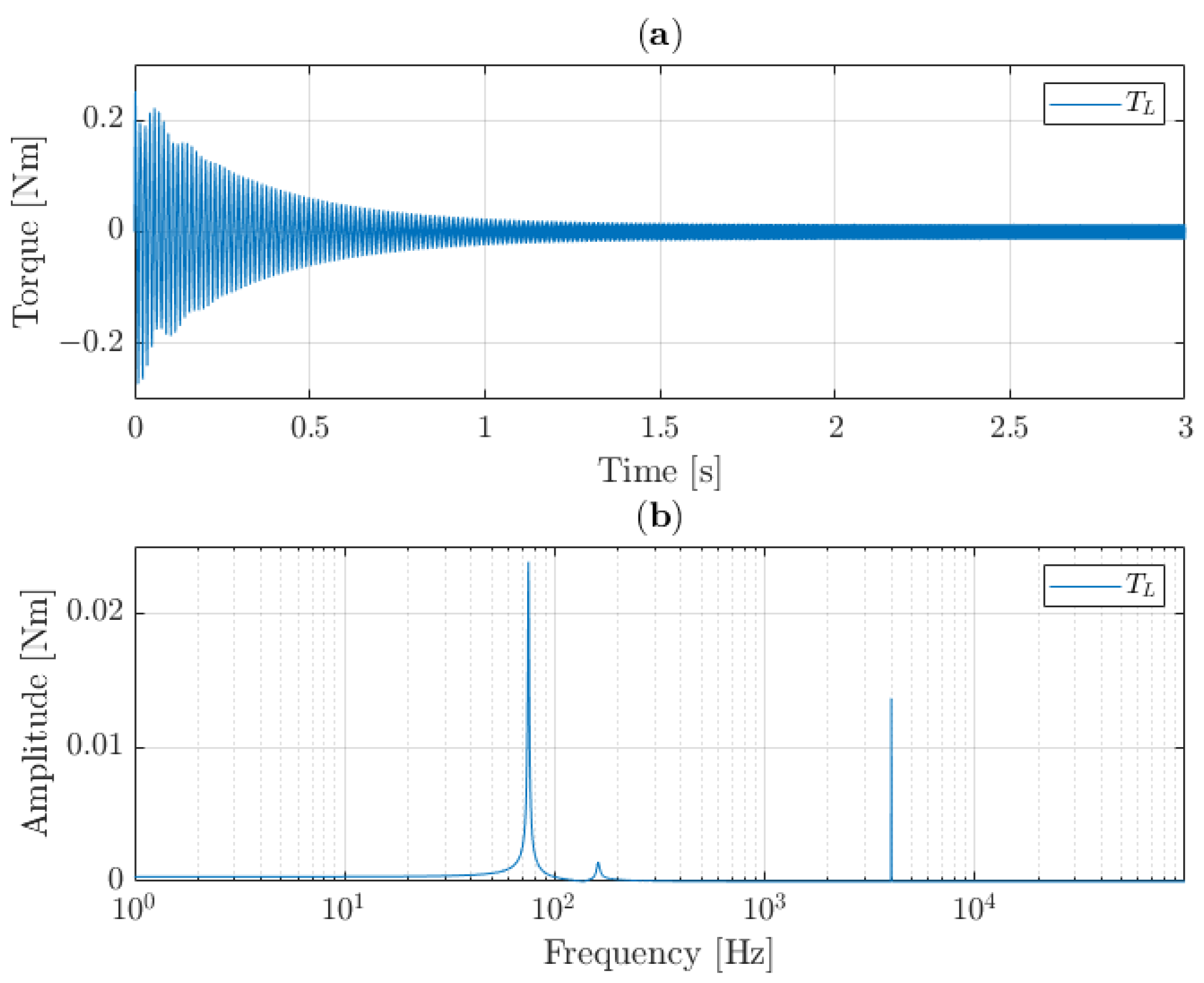
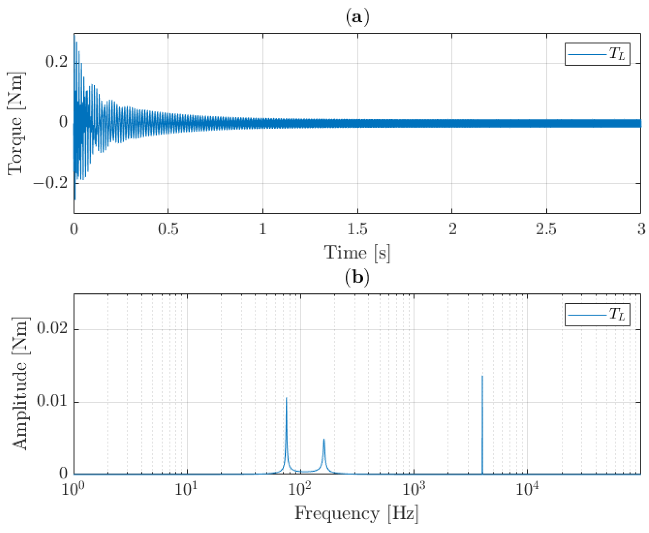
To confirm this approach, the interleaving strategy was first used on a simple sinusoidal input. Both motor inputs received a sinusoidal input according to (
10) with a frequency of 4 kHz and amplitude of 10 Nm, while the torque at the load was monitored. The torque input signal of motor M2 was shifted by an angle
, and the impact of this shift was observed.
In
Figure 10, the result when
is shown. Both signals are synchronized. It can be seen that this results in a transient oscillation at the mechanical resonance frequencies of the system; the 4 kHz is weakened by the mechanics. After the transient period, a small oscillation at 4 kHz remains, and no effect is visible at the mechanical resonance frequency.
The interleaving strategy, with
, is shown in
Figure 11. Here, similar behaviour is visible. After the transient phase, the resonance oscillations die out. Only the weakened sinusoidal input remains. Again, in the steady state of the simulation no effect of the interleaving strategy is visible, as the high frequency is significantly weakened by the mechanical structure. The benefit of the interleaving strategy is visible in the transient phase of this simulation. Using this technique, the oscillation is much smaller in amplitude at the first resonance mode and slightly increased at the second mode, as would be expected by observing the bode characteristics in
Figure 9. It can therefore be concluded that the interleaving strategy only has a beneficial impact on the mechanical resonance of the system during transient behaviour.
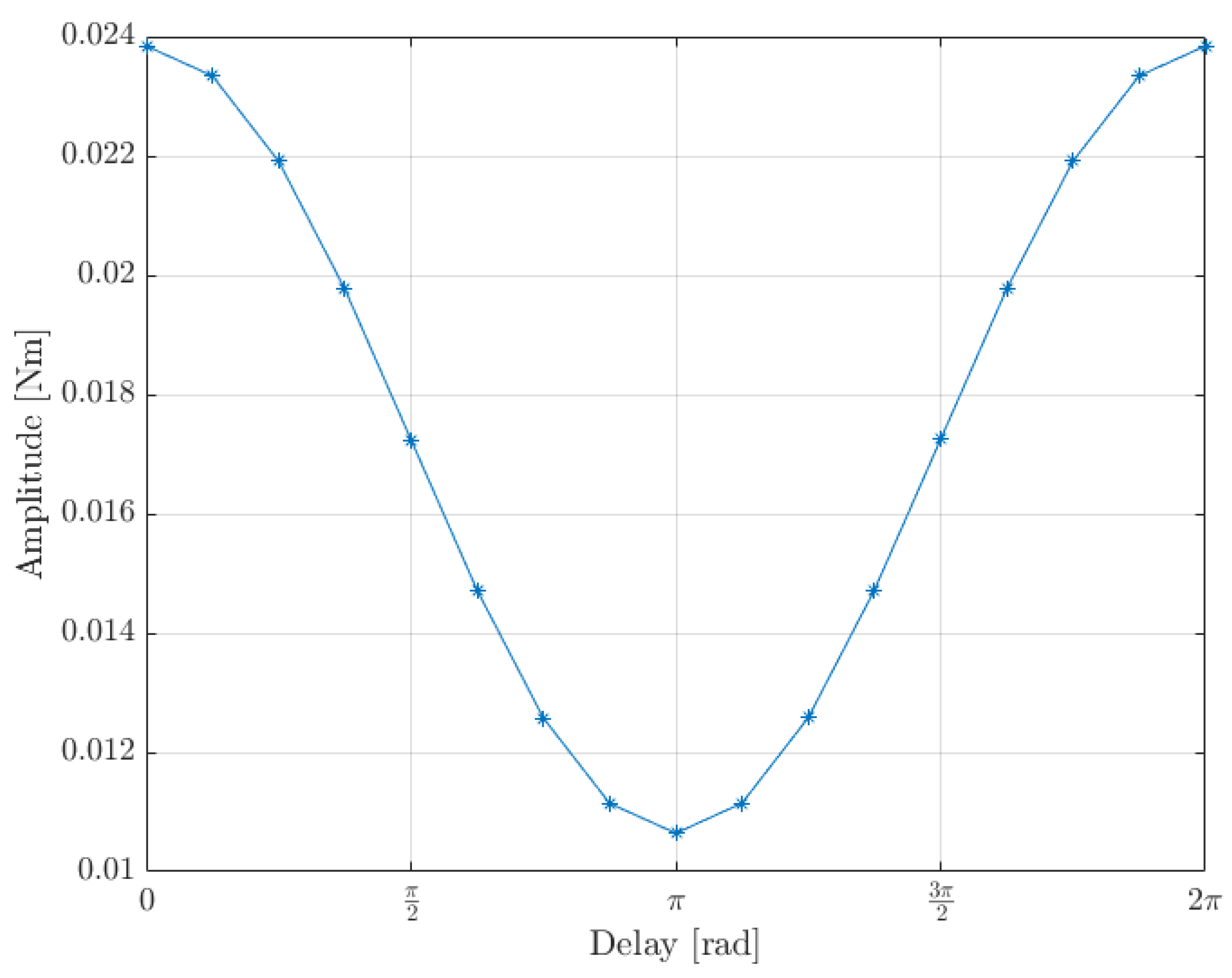
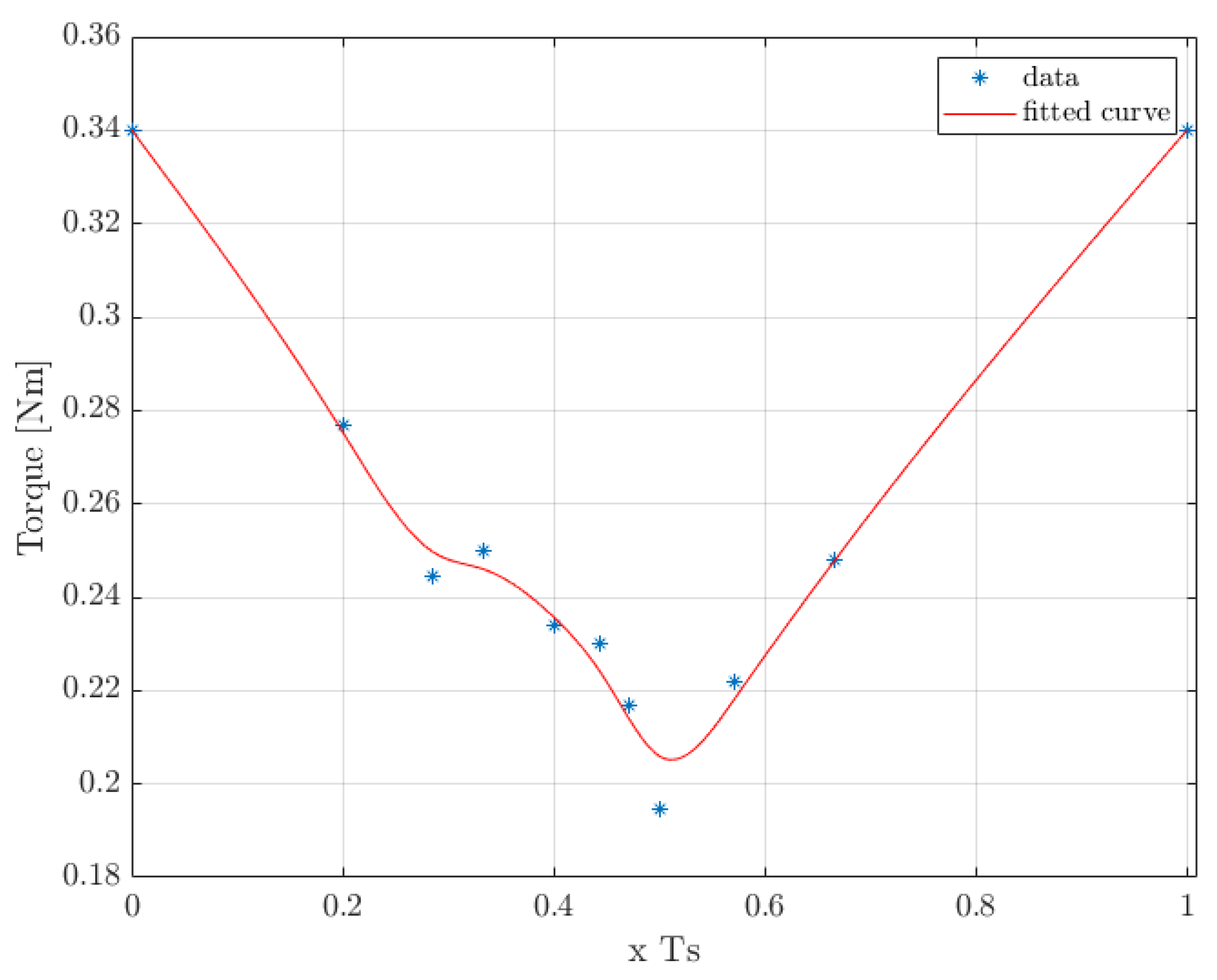
In this implementation of interleaving, a delay of half the signal frequency was chosen. To determine whether or not this was the optimal choice, different delay lengths were compared. In
Figure 12, the amplitude of the first resonance mode is compared for various values of
from 0 to
. By shifting the second motor signal with a varying offset, a clear minimum was found at half the signal frequency.
4.2. Implementation of Interleaving Control on a Modular Drivetrain
In the modular drivetrain under consideration, the PWM generation for the power electronic inverters is the source of the torque ripple; a ripple in the motor current is thereby produced, which in turn results in a ripple in the torque generation. This creates a mechanical resonance oscillation in the drivetrain, even in steady state speed conditions. Therefore, the interleaving strategy could improve the behaviour of the drivetrain and counteract these oscillations.
Figure 7c shows the load torque output during the simulation of the modular drivetrain when the interleaving control strategy is used. Here, the torque ripple is reduced to 0.20 Nm, which is 17% lower than during the benchmark scenario. With this simulation, it can be concluded that the interleaving control strategy has a similar impact on the modular drivetrain, as outlined in
Section 4.1. The oscillations from both motor inputs are brought into counterphase through the interleaving control, and the overall impact at the first resonance mode is thus reduced. However, it should be noted that when using the interleaving control strategy, a harmonic of this resonance frequency (2*
) becomes more pronounced. The harmonic (2*
) oscillation is increased because this frequency is close to the second resonance mode, and therefore the two oscillations are brought back into phase with each other by interleaving, as illustrated in
Figure 9. The impact on the system is therefore increased. Based on these simulation results, it can be concluded that the interleaving control strategy improves the torsional vibration behaviour of a modular design, and makes it competitive with a traditional machine design regarding this performance indicator.
The previous simulations were carried out with a controller PWM switching frequency of 4 kHz. This was chosen to match the operating conditions of the setup used in
Section 5. However, modern power electronics make it possible to run a motor controller at higher PWM switching frequencies. In order to evaluate the impact of the PWM switching frequency on the torsional vibrations in a modular drivetrain, the simulations showcased in
Figure 7 were repeated with a switching frequency of 10 kHz.
In these simulations, it was observed that the overall torque ripple introduced by the motors had a smaller amplitude. As the PWM switching frequency increases, the resulting motor current ripple decreases. Therefore, the resulting torque ripple can be expected to be smaller.
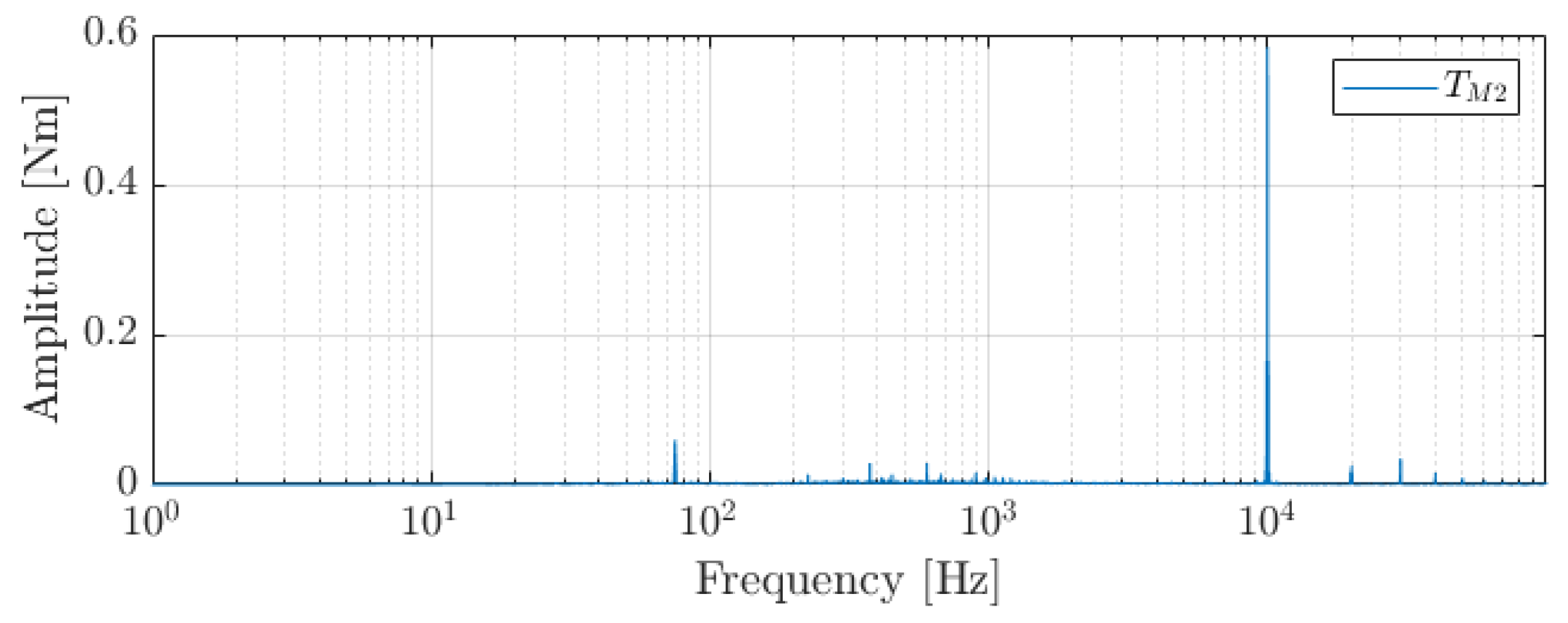
Figure 13 shows the frequency spectrum of the torque input from motor M2. The 10 kHz switching frequency is clearly present, though with a 60% smaller amplitude when compared to the simulations at 4 kHz in
Figure 6.
The comparison between the benchmark and modular drivetrains at 10 kHz is illustrated in
Figure 14. Similar to the previous simulations shown in the modular scenario without any form of torque ripple control, there was a 36% increase in torsional vibrations at the first resonance. When implementing the interleaving control strategy, these vibrations were reduced by 81% compared with the benchmark, a much better result than the 17% reduction simulated at 4 kHz. This indicates that a modular drivetrain design could have a significant beneficial effect on torsional vibrations over traditional designs.
6. Discussion
The goal of this paper is to investigate the impact of a modular design on the torsional vibrations in the drivetrain. A negative impact is observed in the modular design when no control measures were used. Interleaving is proposed as a control strategy to mitigate this negative impact.
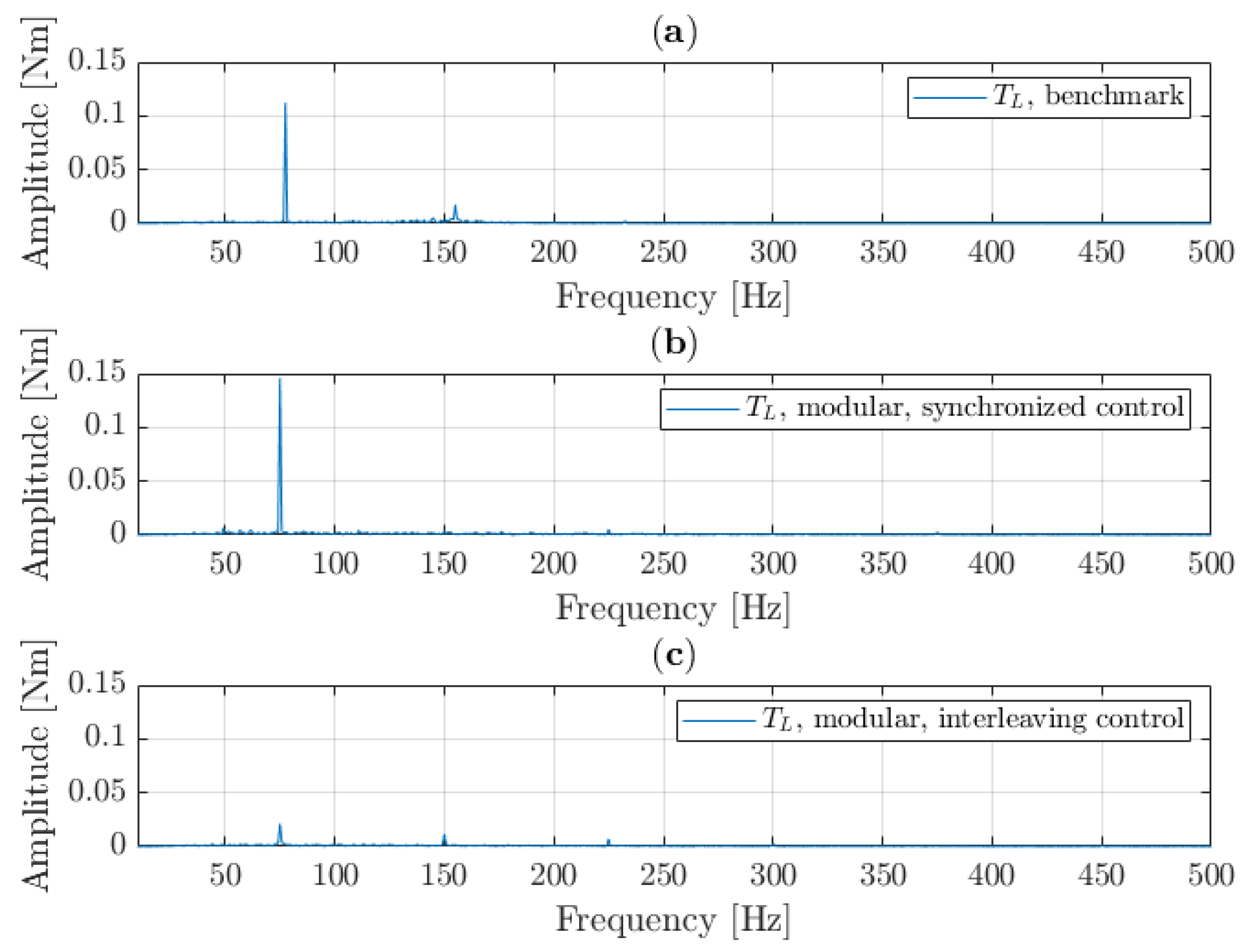
Table 3 summarizes the most important findings of this paper with respect to interleaving in modular drivetrains. The measured drivetrain performance is in line with the simulated behaviour. Overall torsional vibrations at the resonance frequency are slightly lower than in the simulations, e.g., 0.21 Nm measured vs. 0.24 Nm simulated in the benchmark scenario. The behaviour of the modular drivetrain with synchronized control did not impact the performance as negatively as was expected from simulation. Nevertheless, an increase in vibrations of 62% was observed, which is unacceptable. Interleaving proved an effective method to mitigate this negative impact, and reduced the vibrations by 10% compared to the benchmark.
Validation of the simulations using a PWM switching frequency of 10 kHz was not possible due to the limitations of the setup. However, because simulations with a PWM switching frequency of 4 kHz can properly represent the measured behaviour, it is assumed that the simulations with a PWM switching frequency of 10 kHz conducted with the same model represent a decent portrayal of the expected behaviour, thus demonstrating that if a higher switching frequency is used, the interleaving strategy can act as an active method to dampen torsional vibrations in the mechanical drivetrain.
The performed simulations and measurements were focused on the available setup. The results, however, are not limited to this particular drivetrain, and are more widely applicable in modular systems. The above-mentioned examples, such as weaving looms and electric vehicles, likewise face challenges with torsional vibrations. For each drivetrain that can be modelled with the presented model in
Figure 2, the technique of interleaving can be implemented in these applications and should result in similar improvements in drivetrain performance concerning torsional vibrations.
The presented results used steady-state conditions, i.e., constant speed and constant load torque, to evaluate the performance of a modular drivetrain. In subsequent research, more dynamic load cases might be investigated. Implementing a variable load that changes with angular position and/or using varying speed conditions could further highlight the benefits of a modular drivetrain over traditional machine designs in more industry-relevant operational conditions.
7. Conclusions
Modularity is presented in the literature as a novel approach to machine drivetrain design. It shows promising results in creating machines that are more easily adapted to varying load cases. However, using a modular setup has an impact on the performance of the drivetrain. This paper presented the torsional vibrations behaviour of a simplified modular setup. A model of a mechanical drivetrain and electric drives was used to simulate drivetrain behaviour in order to investigate this issue. It was determined that a modular system introduces a negative impact on the drivetrain’s torsional vibrations if the control of the modular drivetrain is not properly implemented.
Interleaving was proposed as a control method to mitigate the negative impact created by the additional source of torque ripple in modular drivetrains. Simulations and experimental validation demonstrated that a modular drivetrain with interleaving control is able to match and even outperform the set benchmark scenario. Therefore, it is concluded that modular drivetrains show competitive potential compared to traditional designs with respect to the issue of torsional vibration.


