Article

X-Shaped Structure-Based Modeling and Control for a Stable Platform with a Series Elastic Actuator

1
Institute of Robotics and Automatic Information Systems, College of Artificial Intelligence, Nankai University, Tianjin 300350, China
2
Tianjin Key Laboratory of Intelligent Robotics, Nankai University, Tianjin 300350, China
3
Institute of Intelligence Technology and Robotic Systems, Shenzhen Research Institute of Nankai University, Shenzhen 518083, China
*
Author to whom correspondence should be addressed.
These authors contributed equally to this work.
Machines 2022, 10(6), 430; https://doi.org/10.3390/machines10060430
Submission received: 22 April 2022 / Revised: 27 May 2022 / Accepted: 27 May 2022 / Published: 30 May 2022
(This article belongs to the Section Automation and Control Systems)

Abstract

:
Stable platforms are widely used in many fields to keep the environment stable for the load under the influence of the motion of the craft and other carriers. However, its stability has always been an important and serious challenge for researchers. In order to further improve its shock absorption performance, a dynamic model based on the stable platform with the series elastic actuator (SEA) is established. Meanwhile, a dynamic reference trajectory based on the X-shaped structure is designed for ignorance of the beneficial nonlinearity in the fixed reference trajectory of the stable platform. In addition, a backstepping control method is proposed to accomplish stronger and faster stabilization with more robustness. Simulations are carried out, and the effectiveness of the proposed method is verified by comparative simulations with a PID controller.

1. Introduction

In order to maintain system stability, it is important to eliminate oscillation and vibration. This problem is widespread in many systems, such as flexible-joint robots and crane systems [1,2,3,4]. Stable platforms are also widely used to maintain a stable working environment for equipment [5,6]. They are used in a variety of bluescenarios such as shipboard and mobile platforms. For example, radar antennas, anti-aircraft guns, gravimeters, and other equipment installed on ships or tanks need to eliminate the impact of environmental-induced ship sway or vehicle bumps [7]; mobile cameras need gimbals as support platforms to eliminate camera shake or displacement interference with picture quality [8]. However, most existing stable platforms are connected by rigid actuators, while there is less research on flexible actuators. Rigid actuators have the advantage of a simple structure and easy implementation, but their output torque accuracy is difficult to meet the requirements with the iterative upgrading of products. In addition, rigid actuators often make the mechanical system get stuck due to assembly errors and other problems. In recent years, flexible actuators have begun to receive attention. The advantages of flexible actuators are that they can achieve more accurate torque output, smoother motion, and higher error tolerance by adding some energy absorption and buffer structures.
The stable platform discussed in this paper adopts the flexible actuator—series elastic actuator (SEA). The SEA connects the elastic element in series between the motor output and the end-effector, which reduces the peak acceleration, and the output is not susceptible to interference from external factors [9]. In comparison with rigid actuators, SEAs have the characteristics of impact resistance, low energy consumption, and high torque output accuracy [10]. SEAs can be divided into linear SEAs and nonlinear SEAs [11]. In detail, early studies focus on linear SEAs, which have been widely used in the field of human–robot interaction [12]. J. Hurst et al. use linear SEAs to reduce the energy loss during robot motion [13]. A. Jafari et al. use them to reduce the peak motor power [14]. Recently, some researchers have used viscoelastic elements or nonlinear mechanical structures to replace the springs in SEAs, thereby facilitating the emergence of nonlinear SEAs. Compared to linear SEAs, nonlinear SEAs have many benefits, such as a larger range of movement and inherent damping [15]. Owing to the built-in elastic element, nonlinear SEAs have a passive immunity mechanism against disturbances. The nonlinear SEA is adopted in the stable platform of this paper. However, in contrast to the active control, the passive immunity mechanism has a delay and cannot respond to the disturbance in a targeted manner [16]. In addition, the existing stable platform based on the SEA cannot exploit the beneficial nonlinearity in the perturbation. Therefore, the X-shaped structure is introduced into the stable platform. It is used as a virtual component to generate the desired trajectory.
The X-shaped structure, inspired by the stability of birds in motion, has been widely studied for car shock absorbers. As a compliant vibration isolation system, the X-shaped structure can take full advantage of the beneficial nonlinear characteristics, including nonlinear stiffness and nonlinear damping, to improve the control performance [6]. The X-shaped structure is increased to two layers; new nonlinear damping is introduced into the X-shaped structure model to improve its damping characteristics, suppress the resonant peak, and maintain the vibration isolation performance in the non-resonant region [17]. A new compensation mechanism is introduced to solve the problem of the input hysteresis [18]. In addition, the neural network is proposed to approximate the unknown dynamics, and the finite-time adaptive control is adopted. In [19], the fuzzy logic system is designed to compensate for system parameter uncertainty, external interference, and input dead time saturation; the tracking error can converge to zero in a limited time. Aiming at making full use of the beneficial perturbation, an energy-saving robust saturation control method is designed; meanwhile, the bounded perturbation and the actuator saturation constraints are taken into consideration to achieve less energy consumption [20]. To sum up, the X-shaped structure is used as a biological vibration isolation system, which allows the system to take advantage of beneficial nonlinear properties and effectively improves control performance. However, this advantage of the X-shaped structure has not been applied to the perturbation suppression of the stable platform.
In this paper, to obtain better stabilization performance, we establish a dynamic model based on a stable platform with the SEA. The X-shaped structure is designed to generate the dynamic reference trajectory for the exploitation of beneficial nonlinearity. Figure 1 shows the overall control block diagram of the stable platform, where the desired trajectory is obtained according to the X-shaped structure. The SEA is controlled as the main actuator component in the stable platform to track the desired trajectory. A backstepping controller is designed. Then, simulations are carried out to verify the effectiveness of the proposed method.
The main contribution of this paper is as follows:
1
The X-shaped structure is introduced to generate the dynamic reference trajectory;
2
A backstepping controller is proposed for the stable platform;
3
Comparative simulations are carried out to verify the effectiveness of the proposed method.
The basic structure of this paper is as follows: the model of the stable platform with the SEA based on the X-shaped structure is established in Section 2, the backstepping controller is proposed in Section 3, and simulations are carried out in Section 4.

2. X-Shaped Structure-Based Modeling for the Stable Platform with the SEA

This section is structured as follows: first, the stable platform and the SEA are introduced; then, the X-shaped structure is introduced to provide the reference trajectory. Our overall control objective is to stabilize the load of the stable platform by trajectory tracking. Detailed analysis will be provided in the subsequent subsections.

2.1. Modeling of the Stable Platform

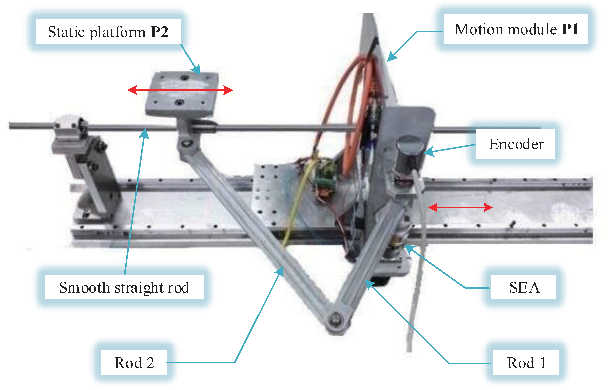
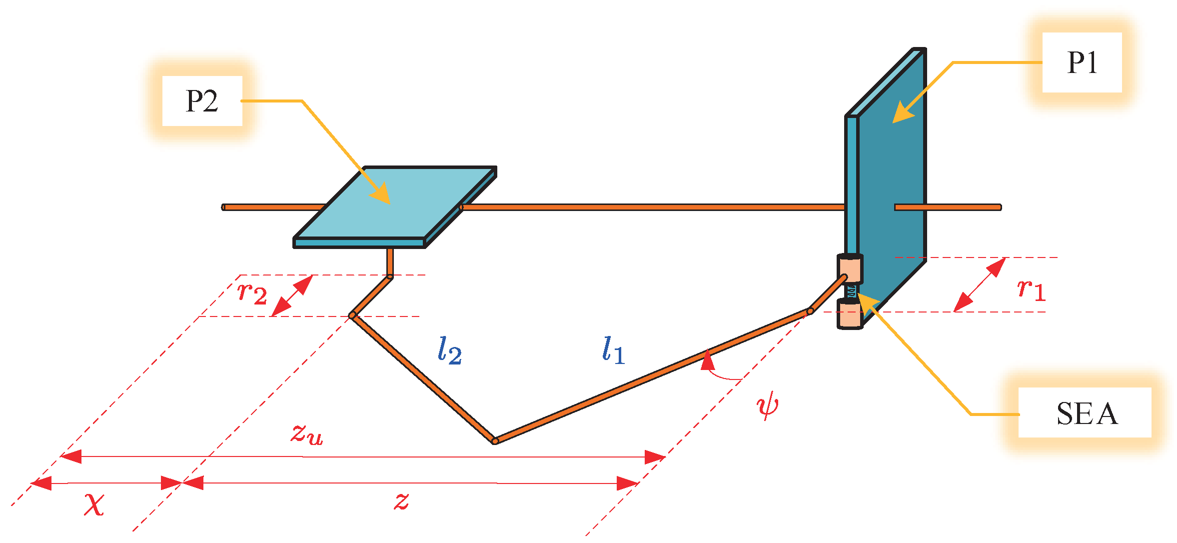
Figure 2 shows the schematic diagram of the stable platform with the SEA [21]. This platform can be divided into the motion module P1 and the static platform P2. P1 and P2 are connected by two rods (named Rod 1 and Rod 2, respectively). P1 is fixedly connected to the smooth straight rod and can slide on the smooth guide rail. P2 can slide on the smooth straight rod. The movement of P1 can be measured by the encoder. The torque output of the SEA can drive Rod 1 to move and change the position of P2. Regarding the motion of P1 under external force as the vibration signal, the control objective is to keep the position of P2 unchanged under the signal. Some relative parameters are listed in Table 1.
As shown in Figure 3, z is set as the distance between P1 and P2. ψ denotes the joint angle between the axis of P1 and Rod 1. According to the geometric relationship, the following equation can be obtained as
z = l 2 2 ( l 1 cos ψ + r 1 r 2 ) 2 + l 1 sin ψ .
The Jacobian matrix of the stable platform can be obtained by deriving z with respect to ψ as follows:
J = ( l 1 cos ψ + r 1 r 2 ) l 1 sin ψ l 2 2 ( l 1 cos ψ + r 1 r 2 ) 2 + l 1 cos ψ .
Here, the mass of Rod 2 is distributed to Rod 1 and P2 in a certain proportion. According to the virtual work principle, the dynamic model of the stable platform can be established as
m b c χ ¨ δ χ = ( τ S E A I a b ψ ¨ ) δ ψ ,
where χ ¨ represents the movement acceleration of P2, δ χ represents the Cartesian space displacement, δ ψ represents the joint space displacement, m b c represents the equivalent mass of P2 and can be calculated by m b c = 1 2 m b + m c , I a b represents the equivalent rotational inertia of Rod 1 and can be calculated by I a b = ( 1 2 m a + 1 2 m b ) l 1 2 , and τ S E A denotes the output torque generated by the SEA.
By substituting δ χ = J δ ψ into (3), the dynamic model of the stable platform can be obtained as follows:
τ S E A = I a b ψ ¨ + J m b c χ ¨ .
Furthermore, the desired output of ψ can be obtained according to the desired output of z based on (1). The desired output of τ S E A can be obtained from the desired output of ψ according to (4). In the range ψ 0 , π 2 , z increases monotonically with the increase of ψ , and there is an inverse function of (1) as follows:
ψ = arccos 0.5 z 2 6 25 z 2 0.25 z 2 + 0.01 z 2 + 0.01 ,
where the values of parameters have been introduced to avoid the expression being too long. The subsequent equations are all dealt with like this.
Considering that χ = z u z can be obtained according to Figure 3 ( z u represents the displacement of P2), by substituting it and (5) into (4), the expected output torque of the SEA is derived as follows:
τ S E A _ d = I a b ψ ¨ + J m b c ( z ¨ u z ¨ ) ,
where ψ ¨ can be calculated as follows:
ψ ¨ = d 2 ψ d z 2 z ˙ 2 + d ψ d z z ¨ = 20 5 z 4 ( 88212.5 z 2 σ 2 1274375 z 4 σ 2 + 6500000 z 6 σ 2 + 6250000 z 8 σ 2 226825 z 2 + 3563125 z 4 21718750 z 6 + 25000000 z 8 + 312500000 z 10 2109 σ 2 + 5166 ) / [ σ 2 3 2 σ 1 2 z 3 ( 20 z 2 σ 2 45 z 2 + 500 z 4 0.8 σ 2 + 2 ) 3 2 ] z ˙ 2 + 0.5 z + 1.25 z 3 σ 4 0.4 z σ 3 + 10 z σ 3 z 2 + 0.01 ( z 2 + 0.01 ) 2 0.25 σ 3 2 z ¨ ,
where σ 1 = 100 z 2 + 1 , σ 2 = 6 25 z 2 , σ 3 = z 2 σ 4 2 0.05 z 2 + 0.02 , σ 4 = 0.06 0.25 z 2 .

2.2. Modeling of the SEA

The SEA is used to provide flexible drive and accurate torque output. The SEA serves as the main driver of the stable platform to provide precise torque output while introducing a passive immunity mechanism. Figure 4 shows the mechanical structure of the SEA. The end-effector is connected with the output end of the motor through the axial spring, and the motor torque indirectly drives the end-effector. The basic principle of operation is that when the end-effector rotates under the action of an external force, it generates a relative angular difference φ with the motor end. Then, the motor drives the rollers to rotate along the circular orbit to deform the three springs in the middle and generate the output torque [22].
From the analysis of the mechanical structure of the SEA, the following equations can be derived as follows [21]:
sin θ = c φ R r , Δ y = ( R r ) ( 1 cos θ ) , F = 3 k s Δ y , τ S E A = F c tan θ ,
where θ denotes the angle of the roller rolling along the circular arc track, c represents the radius of the motor runner, R represents the radius of the circular arc track, r represents the radius of the roller, Δ y denotes the length of the spring deformation, F denotes the total force generated by the three springs, and k s represents the elastic coefficient of the spring. Among them, k s , c, R, and r are known parameters, as shown in Table 2.
Figure 5 shows the simplified structure of the SEA. According to (8), τ S E A is determined by φ , which is expressed as follows:
τ S E A = f ( φ ) = 3 k s c 2 φ 1 1 ( c φ R r ) 2 1 .
The models of the motor and the end-effector are as follows [22]:
J M θ ¨ M + c M θ ˙ M + d 1 = τ τ S E A , J L θ ¨ L + c L θ ˙ L + d 2 = τ S E A ,
where θ M and θ L represent the rotation angle of the motor and the end-effector, respectively, J M and J L represent the moment of inertia of the motor and the end-effector, respectively, c M and c L represent the Coriolis force factors of the motor and the end-effector, respectively, d 1 represents the unmodeled dynamics and perturbation of the motor, d 2 represents those of the end-effector, and τ is the control input.
Redefining two states as x 1 = θ M θ L , x 2 = θ ˙ M , the above SEA model (10) is changed into a new form as follows [23]:
x ˙ 1 = x 2 θ ˙ L , x ˙ 2 = ( τ f ( x 1 ) c M x 2 d ) / J M ,
where d = J M θ ¨ L + c M θ ˙ L + d 1 .
According to the relationship between ψ and θ L ( Δ ψ = Δ θ L ψ ˙ = θ ˙ L ) and the indirectly measurable characteristics of ψ ˙ , θ ˙ L can be regarded as a compensable disturbance; that is, the model can be rewritten as
x ˙ 1 = x 2 d 1 , x ˙ 2 = ( τ f ( x 1 ) c M x 2 d 2 ) / J M ,
where d 1 = θ ˙ L , d 2 = d . The disturbance term d 1 is compensable. Therefore, one does not need to take care of the parameters J L and L , which vary with θ L and θ ˙ L . The transformed model also shows a more obvious result under the effect of the end-effector motion θ ˙ L [24].
In addition, the control objective can be simplified. According to (9), there is a bijection between τ S E A and φ . Thus, the control objective can be transformed as follows [25]:
τ S E A τ S E A _ d φ φ d .
To sum up, the controller is designed to make x 1 track f 1 ( τ S E A _ d ) , where f 1 ( · ) is the inverse function of (9), and τ S E A _ d can be calculated from (6).

2.3. Dynamic Trajectory Based on the X-Shaped Structure

The purpose of introducing the X-shaped structure is to design a dynamic reference trajectory to replace the original, fixed reference trajectory, so that the beneficial nonlinearities in the vibration signal can be exploited [6,17,18,19,20]. The X-shaped structure is composed of connecting rods, joints, and springs. Figure 6 is the model diagram of the X-shaped structure [6]. L 1 and L 2 represent the length of the left and right connecting rods, respectively. θ 1 and θ 2 represent the initial angles with respect to the horizontal direction, and L 1 sin θ 1 = L 2 sin θ 2 holds constantly. k v and k h are the elastic coefficient of the linear spring in the vertical and horizontal directions, respectively. y is the absolute displacement of the load. z u represents the displacement of the base. y r = y z u represents the relative displacement between the load and the base. v ( y r ) = L 1 sin θ + y r 2 is defined. n x = 4 denotes the number of joints. Specific values of the parameters are given in Table 3.
According to Lagrange’s method, the X-shaped structure dynamic model can be obtained as follows [6]:
m c y ¨ r + h 1 ( y r ) + k v y r + μ 1 y ˙ r + μ 2 n x h 2 ( y r ) y ˙ r = m c z ¨ u ,
where
h 1 ( y r ) = k h 2 L 1 cos θ 1 + L 2 cos θ 2 L 1 2 v 2 ( y r ) L 2 2 v 2 ( y r ) v ( y r ) L 1 2 v 2 ( y r ) + v ( y r ) L 2 2 v 2 ( y r ) , h 2 ( y r ) = 1 2 L 1 2 v 2 ( y r ) + 1 2 L 2 2 v 2 ( y r ) 2 .
As for how the X-shaped structure generates the desired trajectory, the following approach is taken. y r , y ˙ r , and y ¨ r generated from the dynamic equation of the X-shaped structure (14) are used to replace z, z ˙ , and z ¨ in (6), respectively, and the desired output torque τ S E A _ d is obtained. Under the action of function f 1 , τ S E A _ d can be converted to φ d .

3. Controller Design

In this section, the backstepping method is proposed for the stable platform with the SEA, and the details are described below.
The controlled object model is (12), and the control objective is to make x 1 track x d , which can be calculated from f 1 ( τ S E A _ d ) . In this paper, the disturbance is not taken into account in the control law design. The model is transformed as
z 1 = x 1 x d , z 2 = x 2 α 1 ,
where α 1 is the virtual controller.
According to (16), the following equation can be obtained as
z ˙ 1 = z 2 + α 1 x ˙ d .
Substituting (12) into (16), z ˙ 2 can be expressed as follows:
z ˙ 2 = ( τ f ( x 1 ) c M x 2 ) / J M α ˙ 1 .
The virtual controller is designed as α 1 = k 1 z 1 + x ˙ d , where k 1 is the positive control gain. The control law is designed as
τ = J M ( k 1 z ˙ 1 k 2 z 2 z 1 + x ¨ d ) + f ( x 1 ) + c M x 2 .
Substituting the control law (19) into the expression of z ˙ 2 (18), the following equations can be obtained as
z 1 z ˙ 1 = z 1 z 2 k 1 z 1 2 , z 2 z ˙ 2 = k 2 z 2 2 z 1 z 2 .
The Lyapunov candidate function is defined as V = 1 2 z 1 2 + 1 2 z 2 2 , and the derivative of V is
V ˙ = z 1 z ˙ 1 + z 2 z ˙ 2 = k 1 z 1 2 k 2 z 2 2 .
Considering that V is positive definite and V ˙ is negative definite, the control law (19) can asymptotically stabilize the system (12) according to Lyapunov theory.

4. Simulation Results

To verify the effectiveness of the proposed method, the comparative simulations of the PID controller and the proposed backstepping controller are carried out. Parameters of the stable platform mechanical structure can be found in Table 1; parameters of the SEA are shown in Table 2; parameters of the X-shaped structure can be referred to in Table 3. The control objective is to make the angle φ track the desired trajectory φ d generated by the X-shaped structure. The parameters of the PID controller are k p = 500 , k i = 1 , k d = 50 , where k p is the proportional coefficient, k i is the integral coefficient, and k d is the derivative coefficient. The parameters of the backstepping controller are k 1 = 100 , k 2 = 100 . k 1 and k 2 represent the convergence rate of z 1 and z 2 , respectively. The initial value of x 1 is 0. A limit of 30 N·m is added to the control input in the simulations of both controllers by considering the motor drive capacity limitations.

4.1. Simulation 1: Effectiveness Verification

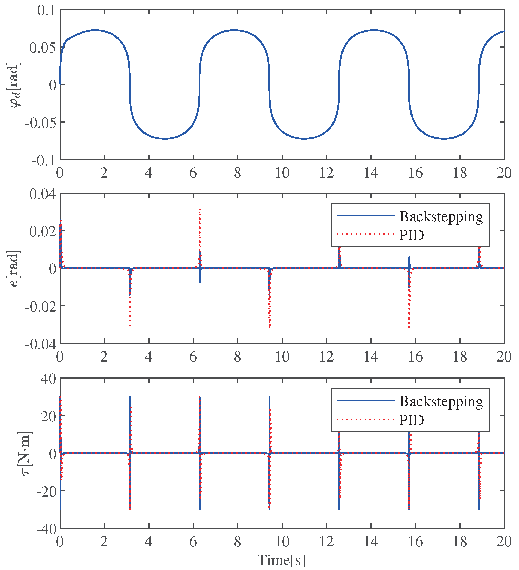
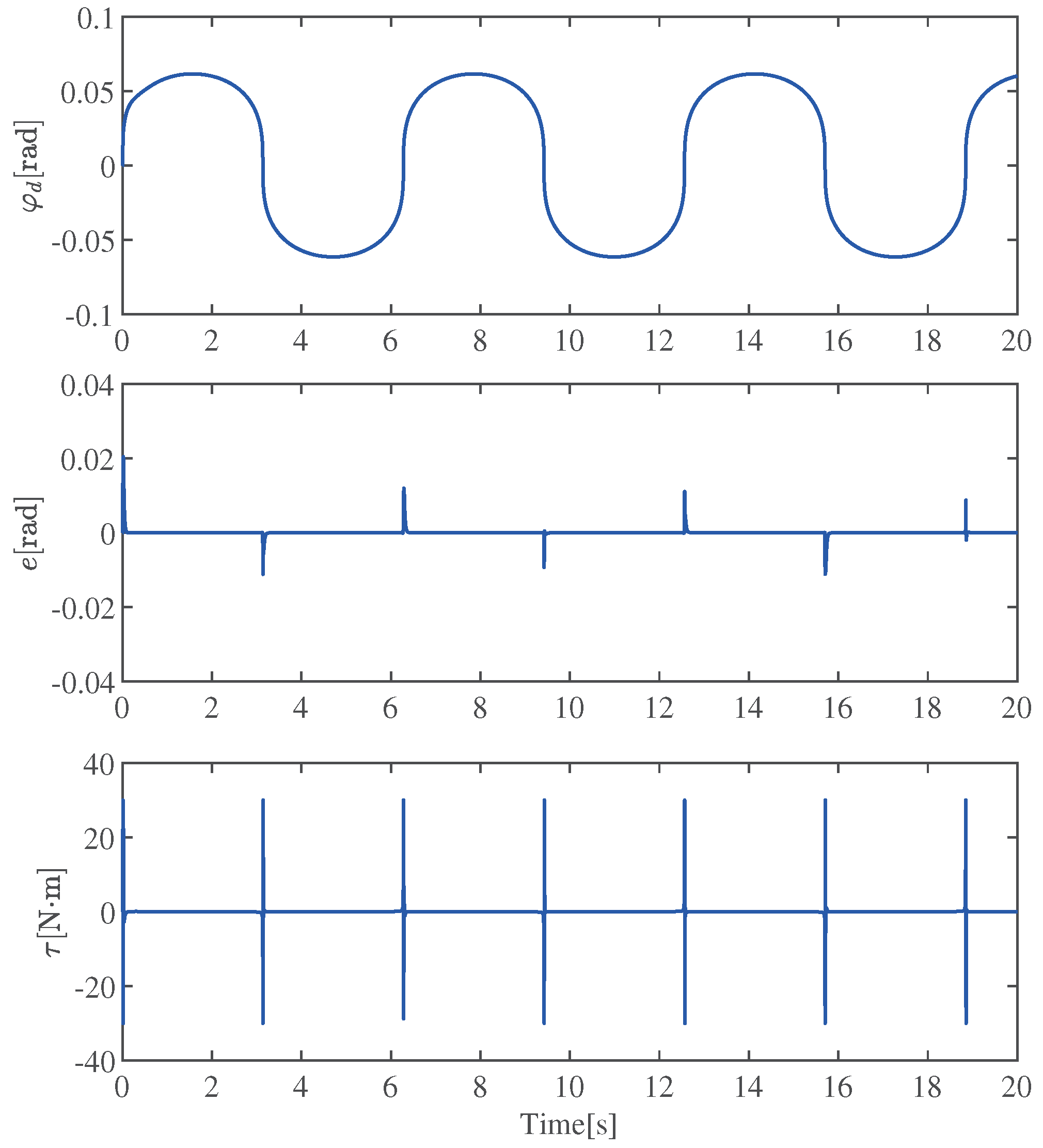
The error is defined as e = x d x 1 , and the tracking results of both controllers are shown in Figure 7. Moreover, the values of the dynamic performance indices are shown in Table 4. t s is defined as the total time that the error exceeds ± 0.0017 rad; v p is defined as the maximum value of e, while v n is defined as the absolute value of the minimum value of e. It can be visualized from Figure 7 that the proposed method has better tracking accuracy than the PID controller and requires less control force. Further, it can be seen from the quantization data in Table 4 that the proposed method’s t s , 0.02 s, is less than that of the PID controller, 0.135 s. In addition, the backstepping v p , 0.026 rad, and v n , 0.014 rad are smaller than that of PID, 0.032 rad, and 0.032 rad.

4.2. Simulation 2: With Disturbances

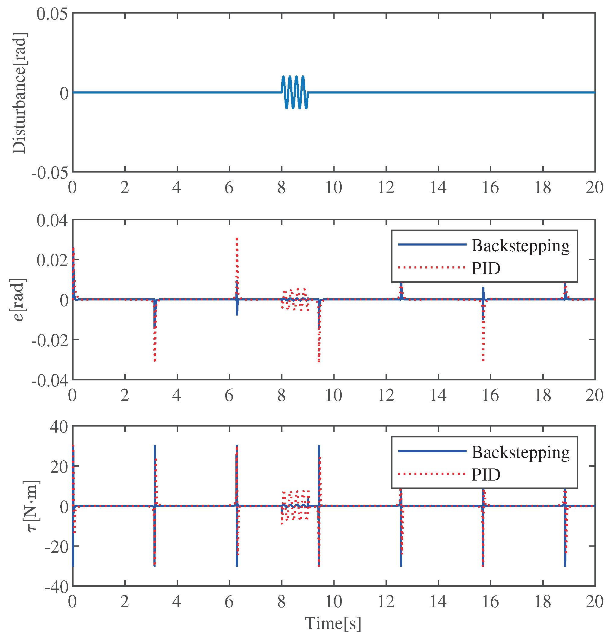
In order to verify the robustness of the controllers, Simulation 2 is performed with the same desired trajectory in Figure 7. The sinusoidal disturbances of amplitude 0.01 rad and the period being 0.25 s between 8 and 9 s are added.
The tracking errors of both controllers are shown in Figure 8. It is obvious from Figure 8 that the backstepping controller has a smaller tracking error. The maximum tracking error of the backstepping controller, 0.0005 rad, is smaller than that of the PID controller, 0.0053 rad. The proposed method can track the φ d of SEA well. In addition, during the perturbation period, the maximum input motor torque τ of the SEA is 3.231 N·m with the backstepping controller smaller than that of the PID controller, 8.603 N·m, which means it has lower hardware drive capability requirements.
Defining a performance index of Simulation 2 as E = 0 20 | e | d t , the index value of the backstepping controller, 0.003, is smaller than that of the PID controller, 0.016. From the data, it can be seen that the backstepping controller has a smaller value of E, which means the backstepping controller has stronger resistance to sinusoidal disturbances than the PID controller.

4.3. Simulation 3: With Parameter Uncertainty

To test the robustness of the controller against parameter uncertainty, m c is changed in Simulation 3 from 10 to 5 kg. Without readjusting the control gain, the proposed method is still able to achieve accurate trajectory tracking, as shown in Figure 9. From Figure 7 and Figure 9, it can be known that the maximum error before and after load mass change are 0.0257 and 0.0204 rad, respectively. The proposed backstepping method can effectively deal with the uncertainty of parameters.

5. Conclusions

In this paper, the dynamic model of the stable platform with the SEA is established. The dynamic reference trajectory based on the X-shaped structure is designed to exploit its beneficial nonlinearity. In addition, the backstepping controller is proposed, and the simulations are carried out to verify the effectiveness of the proposed method. The backstepping controller shows better tracking performance, faster response, and greater robustness against disturbances than the PID controller. Compared with the PID controller, the positive peak of the tracking error of the proposed backstepping controller is reduced by 18.75%, and the negative peak is reduced by 56.25%. Considering the disturbances, the value of the indicator E is reduced by 81.25%. Furthermore, the proposed backstepping method can effectively deal with parameter uncertainty, and the maximum error is changed by no more than 2% before and after changing the parameters. In the future, other more effective control methods will be explored, and the experiment on the physical experiment platform will be conducted.

Author Contributions

Conceptualization, A.T., N.S. and L.S.; methodology, A.T. and T.Y.; software, A.T.; validation, A.T.; formal analysis, A.T.; investigation, A.T.; resources, N.S. and L.S.; data curation, A.T.; writing—original draft preparation, A.T.; writing—review and editing, Q.W. and N.S.; visualization, A.T.; supervision, Q.W. and N.S.; project administration, N.S. and L.S.; funding acquisition, N.S. All authors have read and agreed to the published version of the manuscript.

Funding

This research was funded by the National Natural Science Foundation of China under Grant 61873134, the Natural Science Foundation of Tianjin under Grant 20JCYBJC01360, the China Postdoctoral Science Foundation under Grant 2021M701779, and the Fundamental Research Funds for the Central Universities under Grant 63223058.

Institutional Review Board Statement

Not applicable.

Informed Consent Statement

Not applicable.

Data Availability Statement

Not applicable.

Conflicts of Interest

The authors declare no conflict of interest.

Abbreviations

The following abbreviations are used in this manuscript:
SEASeries elastic actuator
PIDProportional integral derivative

References

  1. Ouyang, H.; Xu, X.; Zhang, G. Energy-shaping-based nonlinear controller design for rotary cranes with double-pendulum effect considering actuator saturation. Autom. Constr. 2020, 111, 103054. [Google Scholar] [CrossRef]
  2. Sun, W.; Su, S.F.; Xia, J.; Nguyen, V.T. Adaptive fuzzy tracking control of flexible-joint robots with full-state constraints. IEEE Trans. Syst. Man Cybern. Syst. 2018, 49, 2201–2209. [Google Scholar] [CrossRef]
  3. Yang, T.; Sun, N.; Fang, Y. Neuroadaptive control for complicated underactuated systems with simultaneous output and velocity constraints exerted on both actuated and unactuated states. IEEE Trans. Neural Netw. Learn. Syst. 2021; to be published. [Google Scholar] [CrossRef]
  4. Liang, D.; Sun, N.; Wu, Y.; Chen, Y.; Fang, Y.; Liu, L. Energy-based motion control for pneumatic artificial muscle actuated robots with experiments. IEEE Trans. Ind. Electron. 2022, 69, 7295–7306. [Google Scholar] [CrossRef]
  5. Hilkert, J. Inertially stabilized platform technology concepts and principles. IEEE Control Syst. Mag. 2008, 28, 26–46. [Google Scholar]
  6. Pan, H.; Jing, X.; Sun, W.; Gao, H. A bioinspired dynamics-based adaptive tracking control for nonlinear suspension systems. IEEE Trans. Control Syst. Technol. 2017, 26, 903–914. [Google Scholar] [CrossRef]
  7. Iqbal, S.; Bhatti, A.I.; Akhtar, M.; Ullah, S. Design and robustness evaluation of an H∞ loop shaping controller for a 2DOF stabilized platform. In Proceedings of the 2007 European Control Conference (ECC), Kos, Greece, 2–5 July 2007; pp. 2098–2104. [Google Scholar]
  8. Patel, B.; Warren, M.; Schoellig, A. Point me in the right direction: Improving visual localization on UAVs with active gimballed camera pointing. In Proceedings of the 2019 16th Conference on Computer and Robot Vision (CRV), Kingston, QC, Canada, 29–31 May 2019; pp. 105–112. [Google Scholar]
  9. Bolívar Nieto, E.A.; Rezazadeh, S.; Gregg, R.D. Minimizing energy consumption and peak power of series elastic actuators: A convex optimization framework for elastic element design. IEEE/ASME Trans. Mechatron. 2019, 24, 1334–1345. [Google Scholar] [CrossRef] [PubMed] [Green Version]
  10. Oh, S.; Kong, K. High-precision robust force control of a series elastic actuator. IEEE/ASME Trans. Mechatron. 2017, 22, 71–80. [Google Scholar] [CrossRef]
  11. Sun, Y.; Tang, P.; Zheng, J.; Dong, D.; Chen, X.; Bai, L.; Ge, W. Optimal design of a nonlinear series elastic actuator for the prosthetic knee joint based on the conjugate cylindrical cam. IEEE Access 2019, 7, 140846–140859. [Google Scholar] [CrossRef]
  12. Bolivar, E.; Allen, D.; Ellson, G.; Cossio, J.; Voit, W.; Gregg, R. Towards a series elastic actuator with electrically modulated stiffness for powered ankle-foot orthoses. In Proceedings of the 2016 IEEE International Conference on Automation Science and Engineering (CASE), Fort Worth, TX, USA, 21–25 August 2016; pp. 1086–1093. [Google Scholar]
  13. Hurst, J.W.; Rizzi, A.A. Series compliance for an efficient running gait. IEEE Robot. Autom. Mag. 2008, 15, 42–51. [Google Scholar] [CrossRef]
  14. Jafari, A.; Tsagarakis, N.G.; Caldwell, D.G. Exploiting natural dynamics for energy minimization using an Actuator with Adjustable Stiffness (AwAS). In Proceedings of the 2011 IEEE International Conference on Robotics and Automation, Shanghai, China, 9–13 May 2011; pp. 4632–4637. [Google Scholar]
  15. Jarrett, C.; McDaid, A. A model inversion procedure for control of nonlinear series elastic actuators. In Proceedings of the 2019 IEEE 16th International Conference on Rehabilitation Robotics (ICORR), Toronto, ON, Canada, 24–28 June 2019; pp. 453–458. [Google Scholar]
  16. Junior, A.G.L.; de Andrade, R.M.; Filho, A.B. Series elastic actuator: Design, analysis and comparison. In Recent Advances in Robotic Systems; IntechOpen: London, UK, 2016. [Google Scholar]
  17. Li, J.; Jing, X.; Li, Z.; Huang, X. Fuzzy adaptive control for nonlinear suspension systems based on a bioinspired reference model with deliberately designed nonlinear damping. IEEE Trans. Ind. Electron. 2018, 66, 8713–8723. [Google Scholar] [CrossRef]
  18. Zhang, M.; Jing, X.; Wang, G. Bioinspired nonlinear dynamics-based adaptive neural network control for vehicle suspension systems with uncertain/unknown dynamics and input delay. IEEE Trans. Ind. Electron. 2020, 68, 12646–12656. [Google Scholar] [CrossRef]
  19. Zhang, M.; Jing, X. A bioinspired dynamics-based adaptive fuzzy SMC method for half-car active suspension systems with input dead zones and saturations. IEEE Trans. Cybern. 2020, 51, 1743–1755. [Google Scholar] [CrossRef] [PubMed]
  20. Zhang, M.; Jing, X. Energy-saving robust saturated control for active suspension systems via employing beneficial nonlinearity and disturbance. IEEE Trans. Cybern. 2021; to be published. [Google Scholar] [CrossRef]
  21. Li, M.; Sun, L.; Zhao, W.; Liu, J. Robust control approach for novel stabilized platform with series elastic actuator. In Proceedings of the 2019 IEEE International Conference on Advanced Robotics and its Social Impacts (ARSO), Beijing, China, 31 October–2 November 2019; pp. 141–146. [Google Scholar]
  22. Wang, M.; Sun, L.; Yin, W.; Dong, S.; Liu, J. A novel sliding mode control for series elastic actuator torque tracking with an extended disturbance observer. In Proceedings of the 2015 IEEE International Conference on Robotics and Biomimetics (ROBIO), Zhuhai, China, 6–9 December 2015; pp. 2407–2412. [Google Scholar]
  23. Gong, X.R.; Chen, X.W.; Yin, W.; Sun, W.C.; Sun, L. Accurate estimation of the spring stiffness in series elastic actuators. In Proceedings of the 2017 IEEE International Conference on CYBER Technology in Automation, Control, and Intelligent Systems (CYBER), Honolulu, HI, USA, 31 July–4 August 2017; pp. 382–387. [Google Scholar]
  24. Wang, M.; Sun, L.; Yin, W.; Dong, S.; Liu, J. Continuous robust control for series elastic actuator with unknown payload parameters and external disturbances. IEEE/CAA J. Autom. Sin. 2017, 4, 620–627. [Google Scholar] [CrossRef]
  25. Wang, M.; Sun, L.; Yin, W.; Dong, S.; Liu, J. Continuous finite-time control approach for series elastic actuator. In Proceedings of the 2016 IEEE Conference on Decision and Control (CDC), Las Vegas, NV, USA, 12–14 December 2016; pp. 843–848. [Google Scholar]
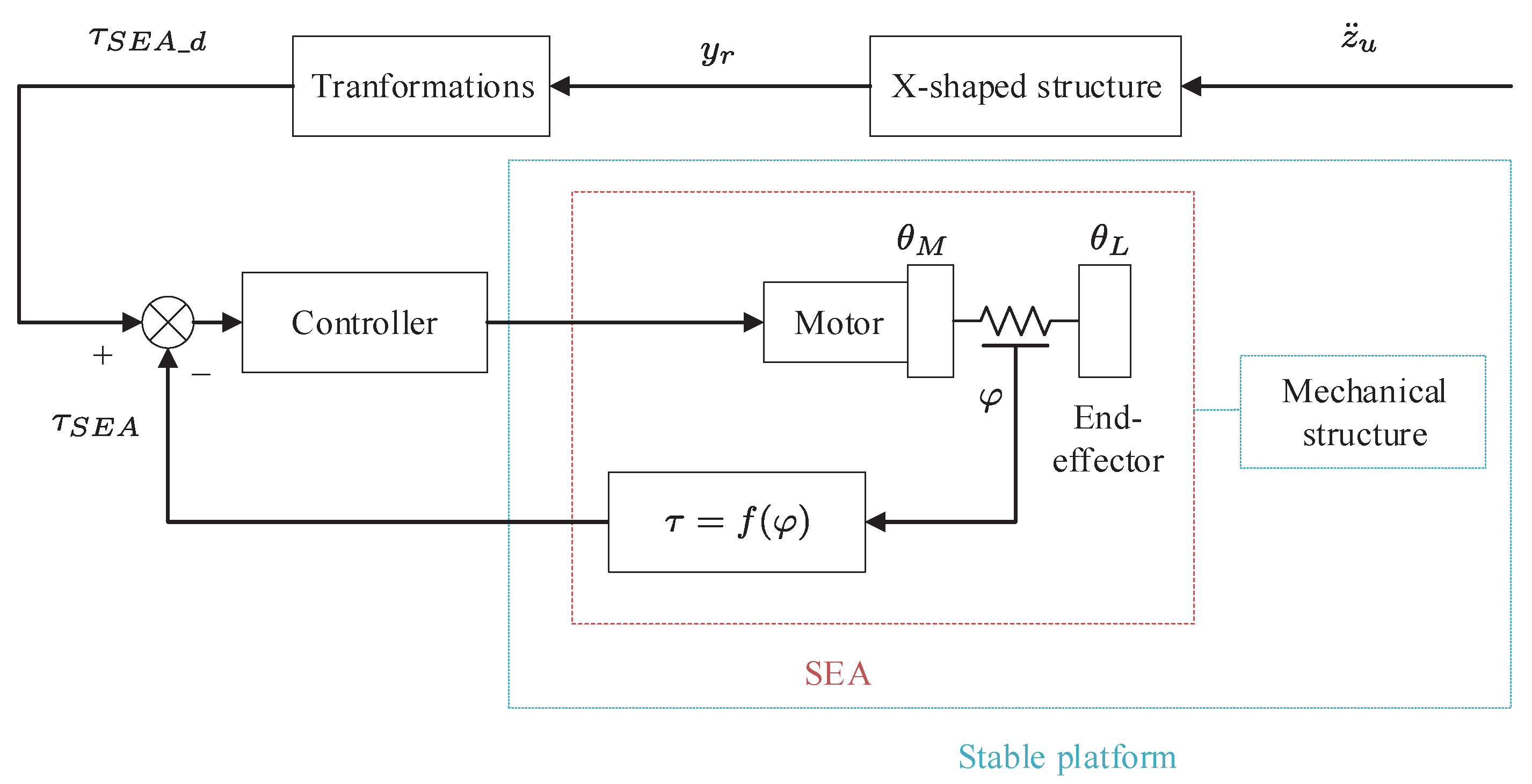
Figure 1. Control block diagram of the stable platform with the SEA based on the X-shaped structure.
Machines 10 00430 g001
Figure 2. Self-built experimental stable platform.
Machines 10 00430 g002
Figure 3. Model of the stable platform with the SEA.
Machines 10 00430 g003
Figure 4. Mechanical structure of the SEA.
Machines 10 00430 g004
Figure 5. Model of the SEA (the end-effector connects to Rod 1).
Machines 10 00430 g005
Figure 6. X-shaped structure (a) with the original state, (b) with the deformation, and (c) the comparison diagram.
Machines 10 00430 g006
Figure 7. Comparative results with m c = 10 kg and no disturbances.
Machines 10 00430 g007
Figure 8. Comparative results with m c = 10 kg and disturbances.
Machines 10 00430 g008
Figure 9. The simulation results with load mass uncertainty.
Machines 10 00430 g009
Table 1. Parameters of the Stable Platform.
ParametersPysical MeaningsValues
l 1 length of Rod 10.2 m
l 2 length of Rod 20.3 m
r 1 distance from P1 to the SEA0.15 m
r 2 distance from P2 to Rod 20.05 m
m a mass of Rod 10.15 kg
m b mass of Rod 20.14 kg
m c mass of the load10 kg
Table 2. Parameters of the SEA.
ParametersValues
k s 13,600 N/m
c0.018 m
R0.020 m
r0.005 m
J M 0.082 kg · m 2
c M 0.75 kg · m 2 / s
Table 3. Parameters of the X-shaped structure.
ParametersValues
k h 500 N/m
k v 250 N/m
L 1 0.1 m
L 2 0.2 m
θ 1 0.167 rad
μ 1 1 Ns/m
μ 2 0.155 Ns/m
Table 4. Values of the Dynamic Performance Indices.
Controllers t s (s) v p (rad) v n (rad)
Backstepping0.0200.0260.014
PID0.1350.0320.032
Improvement85.19%37.50%56.25%
Publisher’s Note: MDPI stays neutral with regard to jurisdictional claims in published maps and institutional affiliations.