1. Introduction
In recent decades, depletion of traditional primary energy sources and harmful effects of fossil fuel emissions have imposed a need for the implementation of more environment-friendly and energy efficient modes of transportation and integration of renewable energy sources. In all areas related to production and consumption of electrical energy, electrical machines are an indispensable component. Previous solutions for the aforementioned applications, based on the use of three-phase machines, are often not the most favorable. The use of multiphase machines and converters, compared to traditionally used three-phase units, is frequently beneficial in eco-friendly applications such as pure electric and hybrid vehicles and vessels, high-power industrial applications, and wind power generation [
1,
2].
Despite intensive research in the field of multiphase machines, there are still a number of challenges in this area that need to be addressed. Adequate stator winding design, i.e., the choice of winding topology and combination of the number of rotor bars and the number of stator slots, can lead to improved performance of multiphase drives [
3,
4,
5]. It is well known that multiphase drives have advantages in post-fault operation (e.g., one open phase) over their three-phase counterparts. For this reason, in order to optimize the control strategy algorithms, two techniques are usually implemented: Minimum losses or maximum torque per amper, which is elaborated in [
6].
Higher order spatial harmonics of stator magnetomotive force (MMF) generate flux density harmonics which cause additional losses in the rotor. Determining the influence of individual spatial harmonics of the MMF on the harmonic losses in the rotor bars and magnetic circuit is very important, as it helps recognize which harmonics should be suppressed during the winding design stage and by means of the control algorithm. Suppression of the most influential MMF harmonics can be introduced as an additional criterion in the design procedure. The influence of MMF harmonics on rotor cage losses has been studied in [
7]. A three-phase induction machine model including effects of time harmonics is presented in [
8] and expanded to include spatial harmonic effects in [
9]. A detailed model of a multiphase machine including MMF spatial harmonics of an asymmetrical six-phase machine is presented in [
10]. However, no detailed analysis of the influence of individual MMF spatial and time harmonics on rotor harmonic (surface) losses in multiphase machines has been reported up to this date.
This paper analyzes the influence of stator winding configuration and phase current waveforms on the rotor harmonic (surface) losses of an asymmetrical six-phase induction machine (6PIM). The specific aspects of MMF distribution in a 6PIM regarding the influence of current components in the non-torque-producing subspace, which is significant in post-fault operation, are given special consideration. The influence of different current components on the generation of losses was emphasized in [
11]. This phenomenon can be important in post fault-operating regimes of the multiphase machines, when current components in various subspaces are present. The currents in the
subspace should be exploited to minimize the losses and maximizing the torque/amper ratio [
12]. A finite element analysis (FEA) based approach is used to calculate the harmonic losses. A dedicated FE model that enables the analysis of the influence of individual harmonics on harmonic losses is developed and introduced. Relating the harmonic losses to specific MMF harmonics is important during the design stage (selecting the stator winding configuration and number of rotor slots) and for the controller design (the control should minimize the MMF harmonics that cause high harmonic losses). Such a detailed analysis of harmonic losses could not be carried out experimentally, and even if it were, would require a different prototype for each analyzed stator winding configuration.
The manuscript is organized through the following sections.
Section 2 presents the basic considerations regarding the design of 6PIM windings, with a special emphasis on the harmonic losses induced in the rotor. In
Section 3, the proposed procedure for the calculation of rotor harmonic losses of a 6PIM with an arbitrary stator winding distribution is presented.
Section 4 presents the results of harmonic loss calculations for several different winding topologies and different phase current waveforms. In
Section 5, a discussion of the obtained results is conducted and the conclusions are derived along with directions of future research work.
2. Main Aspects of 6PIM Stator Winding Design
The starting point of the stator winding design is usually based on the established procedure (methodology) used for the design of three-phase machines and is presented in many electrical machine design handbooks [
13,
14]. The aim of designing the machine windings is to obtain an MMF waveform as close to sinusoidal as possible, while achieving minimal losses and maximal torque per ampere ratio [
15,
16]. A detailed calculation of machine parameters based on the selected stator winding distribution, can be performed using the considerations from [
14,
17,
18,
19]. Recently, an overview was made for the specific problems linked with the design of machines with different phase numbers, focusing on the winding design and calculation of equivalent circuit parameters. In addition to the direct effect of different phase numbers, the impact of injecting higher-order time harmonic components is also analyzed [
20].
In
Figure 1 two configurations of six-phase windings are shown, in which the points indicate homologous ends of windings. In the symmetrical configuration of
Figure 1a, the two three-phase windings comprising the six-phase winding are shifted by 60 electrical degrees. In the asymmetrical configuration of
Figure 1b, the three-phase windings are shifted by 30 electrical degrees.
Since six-phase machines are not yet incorporated as their three-phase counterparts, in practice, the magnetic circuit of a three-phase machine is usually used for the construction of the six-phase machine. In stator winding design process, the number of available slots is related to the spatial distribution of the windings of two three-phase systems. Based on this, it can be concluded that increasing the number of slots has a favorable effect on reducing the content of higher-order harmonics in the MMF excitation. On the other hand, the increased number of phases makes it difficult to achieve an idealy sinusoidal air-gap MMF distribution due to the limited number of slots. Regarding this, it is desirable to use as many slots as possible to achieve a better spatial MMF distribution and to reduce the content of higher harmonics. However, it is important to note that the increasing the number of slots while keeping the same machine volume (circumference) of the machine causes a reduction of the teeth width. The teeth width is limited to a certain minimal value from a mechanical standpoint. Likewise, it is possible that reducing the width of the slot would reduce the available space for the conductors. In doing so, the slot fill factor becomes reduced, because a certain diameter of the conductor is needed for the required current density.
The compromise is to use a stator magnetic circuit with a larger inner diameter, within the limits allowed by the application. Such a multiphase machine has a smaller number of slots per phase than the initial three-phase machine, which results in higher magnitudes of spatial harmonics per phase, which increases losses and, at the same time, heating inside the machine itself. However, the content of spatial harmonics in the resultant MMF may actually be better with a six-phase machine than with three-phase one. On the other hand, the current in the conductors is lower than in three-phase case (more phases for unchanged power), so the disipation is lower. Adequate choice of winding type allows to increase the fundamental harmonics, as well as reduce the spatial harmonics, which are known to cause unwanted torque pulsations, harmonic losses and serious consequences on equipement [
21,
22].
Apart from the distributed windings, which are the most common, 6PIM also uses concentrated windings. Sometimes, due to the increased number of phases, this is often the only feasible option for multi-pole 6PIM applications. In [
23], a comparison of the performance of machines with distributed and concentrated windings is given, where it was concluded that distributed windings have advantages over concentrated windings in terms of increased torque and reduced losses in the rotor cage. The impact of non-sinusoidal power supply on a concentrated-winding 6PIM is processed in [
24], where it has been established that this type of power supply is suitable for operating conditions at higher machine loads, while sinusoidal power supply is advantageous at lower loads.
The time and space dependence of an arbitrary MMF harmonic generated by a single phase is given as:
The designations used in (
1) are defined as follows:
x—observed phase,
—spatial harmonic order,
—electrical angle along the stator circumference,
—time,
—number of series connected turns per phase,
p—number of machine pole pairs,
—the resulting winding factor for th spatial harmonic,
—RMS current value per phase,
—angular frequency of the phase current.
In general, the resulting winding factor for the multi-harmonic component of the MMF is defined as:
where
and
are the distribution and pitch factors for the
th order spatial harmonic, respectively. These two winding factors are defined as:
where
y is the winding pitch,
z is the number of slots per pole, and
m is the number of slots per pole and phase [
4]. To summarize, a larger number of slots gives a better value of the distribution factor, while shortening of the winding pitch gives a better value of the pitch factor. A further improvement in the MMF waveform in terms of reducing slot harmonics can be achieved by skewing of the stator and/or rotor slots.
The use of a two-layer winding with a shortened winding pitch is one of the common techniques that reduces the negative effects due to the existence of higher-order spatial MMF harmonics. Coils of 6PIM with shortened winding pitch often have a better harmonic spectrum than those with full winding pitch. It is concluded that the optimal choice of the slot number is a compromise between reducing losses (reducing the MMF harmonic content), on the one hand, and maintaining the iron core losses at an acceptable value, on the other hand [
19].
Before the mass implementation of PWM converters, the choice between the types of windings was guided by the criterion of eliminating sixth-order harmonics from torque ripples, which is caused by the presence of fifth and seventh stator MMF harmonics [
21]. Particularly, the torque ripple is more pronounced in symmetrical six-phase windings, where circular currents of magnetic equalization are present [
22]. Three-phase and symmetrical six-phase often require pitch shortening to suppress higher-order spatial MMF harmonics (most commonly of the fifth and seventh order). However, in doing so, the fundamental harmonic is reduced as well. For three-phase machines, the optimal winding pitch is in the range from 0.8 to 0.9 [
14]. In the case of symmetrical six-phase windings, the desired value of winding pitch is most often 5/6 [
24]. With the asymmetrical winding configuration, the harmonics of order
are inherently eliminated, and there is often no need for winding pitch shortening to reduce the influence of higher harmonics. For this reason, the asymmetrical six-phase machine is the most common choice for high-power applications [
23,
25].
For the applications where the six-phase drive-group is designed, it is advisable not to use a three-phase machine as a starting machine, but rather to design a dedicated magnetic and electrical circuit. Moreover, with high-power machines, there is an even greater need for purposeful design of windings and magnetic circuit, because with power increasing it is important to reduce losses. Detailed analyses of the winding design methods and their influence on multiphase machine parameters are given in [
20,
25,
26,
27]. When designing the stator winding of a six-phase machine intended to operate at higher power frequencies, special attention should be paid to achieving a distribution of air-gap flux density as close as possible to the sinusoidal form. By doing so, the surface losses caused by higher spatial harmonics are reduced. There are not many papers on the topic of selecting the multiphase machine stator winding topology from the harmonic loss reduction standpoint.
When we consider the existing suggestions for choosing the optimal six-phase winding topology, the number of stator slots and the winding pitch in symmetrical and asymmetrical configurations significantly affect the machine inductances and machine performance. The six-phase machine achieves higher values of starting and peak torque when it has a full winding pitch, compared to the case when the pitch is shortened [
25]. When operating at nominal frequency, where higher breaking torques and small values of the stator current are required, it is desirable to have equivalent inductance of the machine be as small as possible. At higher (PWM) frequencies it is of interest to reduce the current ripple, thus to have a higher value of the equivalent inductance of the machine. The suggested values of winding pitch are proposed in [
25], from the aspect of the desired breaking and starting torque for the six-phase machine. In most scenarios, the six-phase machine is powered from an adequate converter unit, so it is pointless to analyze and compare the value of the starting torque. At the rated supply frequency, it is desirable to reduce the winding pitch by one slot in order to achieve a lower leakage inductance of the six-phase machine. At higher frequencies, in order to obtain the maximum value of the leakage inductance and hence reduce the current ripple, it is desirable to keep the winding pitch in the range from 2/3 to 1 [
24,
25].
To summarize, it is proposed to use a full-pitch stator winding in a 6PIM due to the following reasons:
circulating currents are inherently eliminated, so they do not affect the torque and currents (unlike the symmetrical six-phase topology),
stator leakage inductances are higher with a full-pitch winding, leading to a slight reduction in available torque and fundamental harmonic current, and
stator winding slot fill factor is increased, which allows to increase the phase voltage value, thus compensating for the torque reduction.
All following analyses and discussions are related to the 6PIM. The following subsections provide an overview of harmonic losses and existing 6PIM modeling approaches.
2.1. Harmonic Losses
The assumption of constant parameters, due to the simpler machine model formulation used in most analyses, is physically (and often practically) unjustified. Stator winding design of a 6PIM significantly affects the parameter values and has an impact on the occurrence of the harmonic (surface) losses in the rotor [
28,
29].
Harmonic losses occur in rotor bars and magnetic circuit due to currents induced by higher order air-gap flux density spatial harmonics. The root cause of flux density harmonics and consequential losses are the stator MMF spatial harmonics. Harmonic losses contribute to total losses, thereby reducing overall machine efficiency. Moreover, these losses are concentrated in a small portion of the rotor volume near the outer surface, resulting in high loss density and potential local overheating. It is good practice to take harmonic losses into account, both in efficiency calculations and thermal modeling.
A review of the currently available literature shows that few papers deal with the harmonic losses in the rotor due to high-order stator MMF harmonics [
7]. In particular, the dependence of the MMF distribution on the stator winding topology has already been studied in detail for three-phase machines and approaches for reducing or completely eliminating certain MMF harmonics are well known [
13,
14,
30]. However, certain matters remain unresolved, especially in the field of multiphase machines. The specifics of MMF distribution in multiphase machines should be taken into account when choosing the winding configuration, which has been investigated for the 6PIM to a certain extent, as previously stated. However, the combined effect of particular MMF spatial harmonics at different current electrical harmonics on rotor losses is yet to be addressed in detail. Finally, certain current components of the 6PIM (
plane components) can lead to an increase in higher order MMF harmonics above values achievable in three-phase machines, and hence to higher harmonic losses.
Higher spatial order harmonics are characterized by shorter flux lines which penetrate a smaller part of the rotor volume. Considering this, it is expected that the total harmonic losses will be lower than anticipated. However, the loss density may be very high in a limited volume of rotor bars and teeth. Therefore, a detailed analysis of the influence of individual spatial MMF harmonics on the rotor surface losses is needed to determine which harmonics are the most important to suppress.
As previously stated, the rotor harmonic losses phenomenon is related to the stator MMF distribution. Therefore, this phenomenon should be taken into account when designing the stator winding. While making an effort to reduce harmonic losses, one should take care to maintain the main machine parameters (magnetizing and leakage inductances) at acceptable values.
2.2. Vsd Model of a 6PIM
In order to start the design of a multi-phase drive unit (machine-converter group), a precise machine model, that represents the behavior during all operating modes, is necessary. Due to its advantages over other modeling methods, the Vector Space Decomposition (VSD) model is the most commonly used [
31,
32]. With this approach, the modeling of a 6PIM is based on decomposition of the six-dimensional phase-domain vector space into three orthogonal, two-dimensional subspaces (planes) [
33]:
fundamental () plane,
non-fundamental (), and
zero-sequence () plane.
The first plane is identical to the
plane of a three-phase machine, associated with electromechanical conversion. The
and
planes do not contribute to electromechanical conversion. With this type of decomposition, there are machine variables that are completely uncoupled between the introduced planes, which provides certain advantages from the control aspect [
31,
34].
The VSD model is selected to represent the 6PIM electical quantities in this paper. This model is convenient for spatial harmonic analyses as different vector subspaces are associated with particular MMF spatial harmonics. Namely, the
current components generate the fundamental harmonic and higher-order harmonics of the order
(
). On the other hand, the
plane current components generate harmonics of the order
(
) [
35]. Zero-sequence components generate the third harmonic and its integer multiples. However, as the neutral points of the two three-phase windings comprising the 6PIM stator winding are considered to be isolated in the upcoming analyses, the influence of zero-sequence components will be disregarded. A recent document [
10] investigates the effect of air-gap harmonics mapped into the
and zero subspaces on the modeling and dynamic response of a 6PIM. Afterwards, an improved space harmonic model is proposed and experimentally verified.
3. Materials and Methods
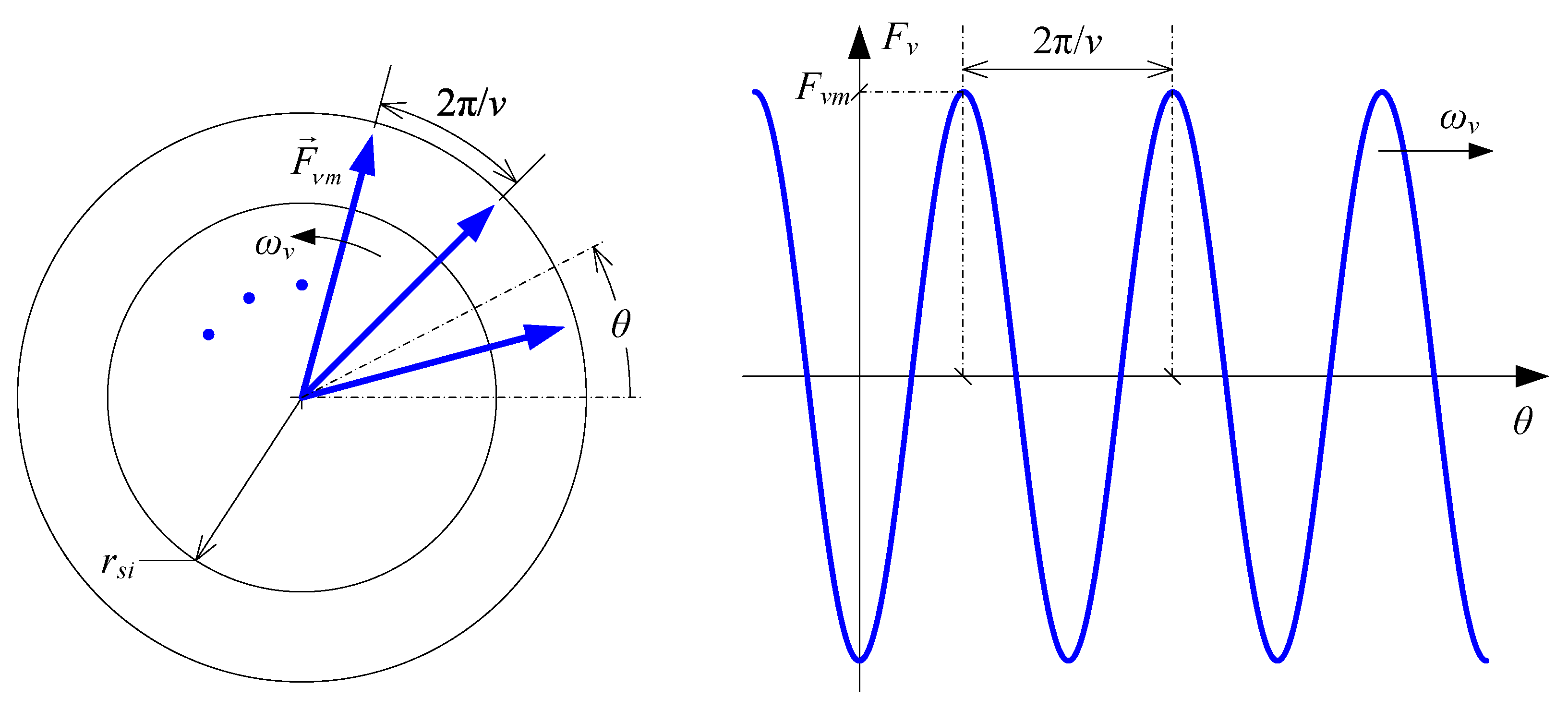
The focus of this study is to determine the contribution of individual stator MMF spatial harmonics to the rotor harmonic losses. An arbitrary MMF harmonic time-space variation, assuming a rotating MMF waveform, is given as:
where
is the electrical angle,
is the magnitude of the
th MMF spatial harmonic, and
is the angular frequency of its variation (rotation). Note that this frequency depends on the frequency of the associated current component as follows:
where
is the frequency of the current harmonic component which generates the
th spatial harmonic. It is important to distinguish the rotating frequency of spatial harmonics from the electrical frequency of the winding current. Note that
can have a positive or negative value, depending on the harmonic order, with positive values corresponding to harmonics of the order
(
), and negative values to harmonics of the order
. In other words, certain MMF harmonics may rotate in a direction opposite to that of the fundamental. The graphical representation of an arbitrary MMF harmonic distribution is given in
Figure 2.
The MMF can be expressed as the line integral of the linear current density along the inner stator circumference. To generate an MMF distribution given by (
4), the corresponding linear current density should have the following form:
where
is the magnitude of the
th harmonic of linear current density, related to the corresponding MMF magnitude as [
13]:
where
is the stator inner radius.
A sinusoidally varying linear current density along the stator circumference needed to generate an MMF waveform given by (
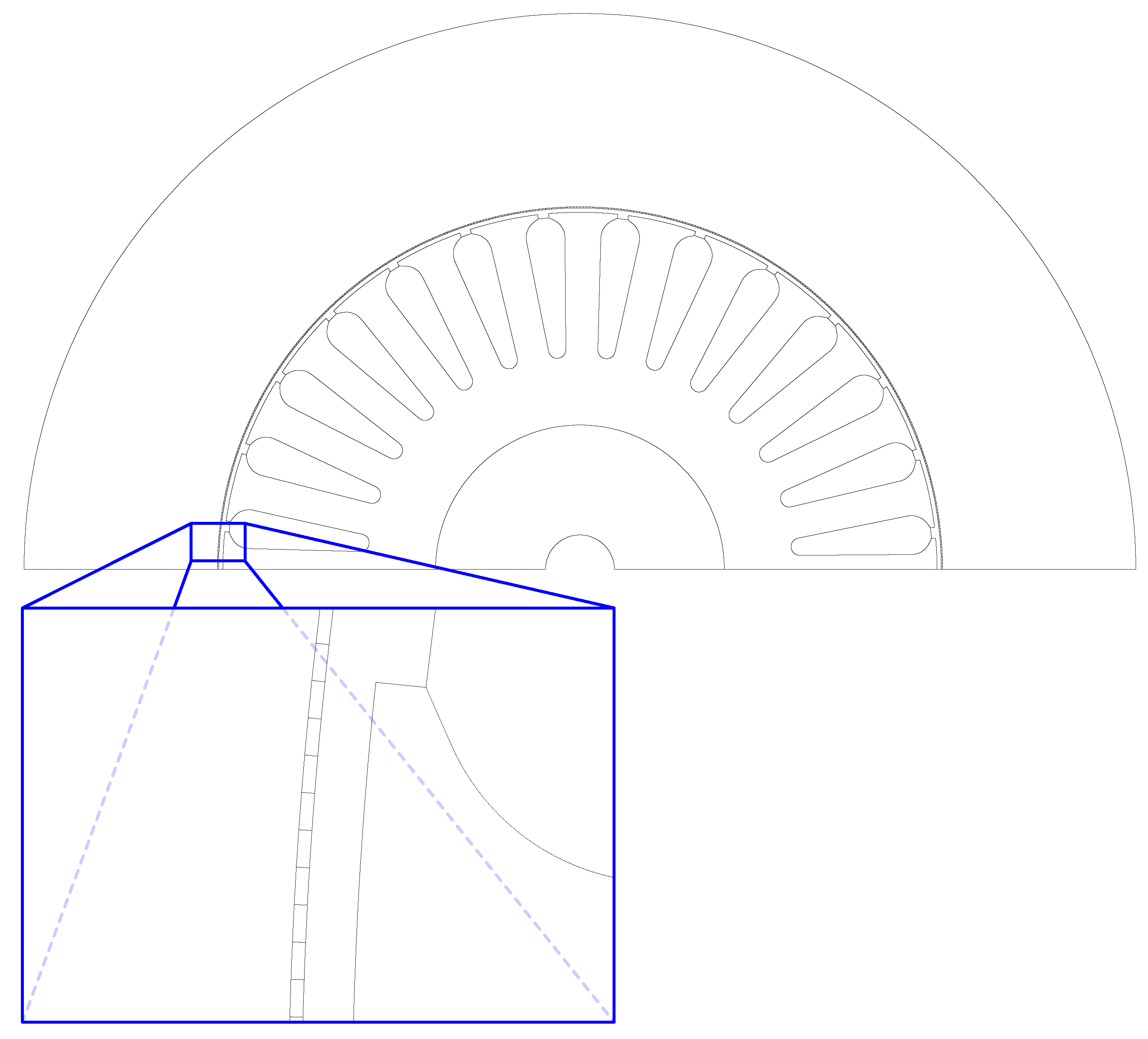
4) is not offered by most commercial FEA software packages. Therefore, dedicated FE model of the investigated machine is developed using the open-source FEMM 4.2 software [
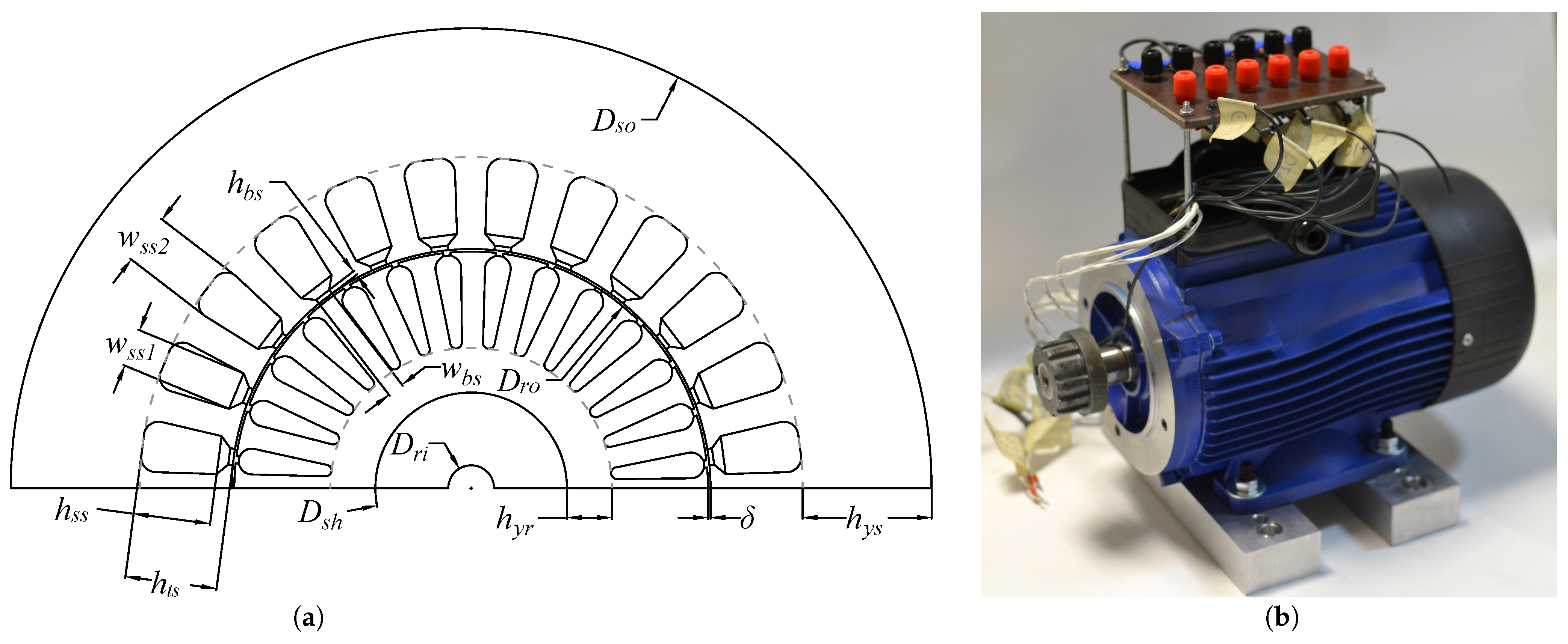
36]. The model is based on the FE model of an existing 2-pole 6PIM prototype with 24 stator slots and 28 rotor slots (bars). The actual stator winding is replaced by a slotless current sheet which approximates a continuous linear current density along the stator inner circumference. The sheet consists of
elementary conductors under two poles, the angular displacement between the conductor being
electrical degrees. According to the Nyquist sampling theorem, spatial harmonics up to the 360th order can be generated with such a winding distribution. The cross-section and design data of the 6PIM prototype are given in
Appendix A and the modified model is shown in
Figure 3. This modified model will be referred to as the LC (Linear Current) model from here on in.
To retain similar magnetic features, the stator outer diameter of the LC model is reduced compared to the original model to keep the yoke height unchanged. To take slotting and teeth saturation into account, the air-gap length is increased according to:
where
is the actual air-gap,
is the effective air-gap, and
is the Carter coefficient of the stator [
30], with an estimated value of 1.1 for the analyzed 6PIM.
To obtain the linear current density distribution given by (
6), the current of the
th elementary conductor of the LC model should be equal to:
Note that the current given by (
9) is a complex quantity. After setting current values for all
conductors, the simulation frequency needs to be set. As the aim of the simulation is to determine rotor harmonic losses, the simulation frequency should correspond to the frequency of currents induced in the rotor. If the
th MMF harmonic is rotating at the angular frequency
, the frequency of rotor currents equals:
where
is the rotating frequency of the
th MMF harmonic and
n is the rotor’s mechanical rotating speed. As previously stated,
can have a positive or negative value depending on the rotation direction of the observed MMF spatial harmonic.
As the LC model allows calculations to be performed for one harmonic at a time, the effect of saturation should be properly accounted for. To due this, each calculation is performed with the FE mesh copied from a solution obtained when only the fundamental MMF harmonic is present. This is done to include main flux saturation, which has the most pronounced effect on the magnetic circuit permeability. The higher order MMF harmonics are then superimposed on the solution obtained for the fundamental MMF to obtain the flux density distribution in a saturated machine.
The loss calculation is conducted for different stator winding types and different supply conditions. In other words, the stator slot number and winding distribution are varied, as well as the phase current waveforms. By doing so, the magnitudes and frequencies of MMF harmonics and resulting losses are varied. The following procedure is repeated for each scenario:
- (1)
The winding distribution and phase current values are defined;
- (2)
The total MMF distribution is determined for the selected winding distribution and phase currents;
- (3)
The MMF spatial harmonic magnitudes are determined by performing Fourier transform on the total MMF waveform;
- (4)
Currents of individual elementary conductors of the current sheet are calculated according to (
9). These values are assigned to the conductors of the FE model;
- (5)
The FEA problem frequency is set according to (
10);
- (6)
The FEA calculation is performed and the losses in rotor bars and magnetic circuit are determined.
Note that steps (4)–(6) are performed for each spatial harmonic individually.
Calculation of losses for each harmonic individually according to the proposed procedure implicitly assumes superposition of losses corresponding to different harmonics. This assumption is valid in terms of bar losses [
8,
9] and eddy-current core losses [
37,
38]. While it is common practice to apply superposition to hysteresis losses as well [
9], more detailed analyses have shown that hysteresis losses generated by higher-order harmonics are more accurately calculated by applying the minor hysteresis loops approach [
37,
38]. Considering that the rotor harmonic frequencies are generally much higher than the fundamental frequency, it is safe to assume that core losses consist mostly of the eddy-current components [
39,
40], rendering the potential error introduced by hysteresis loss superposition tolerable from a practical standpoint.
4. Results
The model described in the previous section is used to analyze the contribution of different stator MMF harmonics to the rotor harmonic losses. The rotor configuration of the original 6PIM prototype (
Appendix A) is retained throughout the analysis. On the other hand, the stator winding distribution is varied, i.e., the harmonic content of the current sheet of the LC model (
Figure 3) is varied accordingly. The stator inner and outer diameter are the same for all analyzed combinations. The following stator slot number/coil pitch combinations are examined (
and
c denote the stator slot number and coil pitch reduction, respectively):
- (a)
, ;
- (b)
, ;
- (c)
, ;
- (d)
, ;
- (e)
, ;
- (f)
, .
The combination (c) corresponds to the actual 6PIM prototype described in the
Appendix A. To maintain the fundamental winding MMF at an approximately constant value, the number of turns per phase is kept the same for all combinations. More precisely, the number of turns per coil is varied as:
where
,
, and
are the number of turns per coil, number of slots, and fundamental winding factor of an arbitrary slot/pitch combination. The same designations without the index “
j” refer to the original 24-slot full-pitch winding (combination (c)).
When no zero-sequence components are present, which is the case in this study, only MMF harmonics of the order
(
) are present. To reiterate, currents in the
plane generate harmonics of the order
(
), whereas the
plane current components generate harmonics of the order
(
) [
35]. Current components in the
plane can appear either at fundamental frequency, due to main flux saturation, winding asymmetry, or supply voltage imbalance, or at high frequencies due to PWM excitation. Currents in the
plane tend to reach high values due to the low input impedance [
4,
24]. It is therefore of interest to examine the cases where
current components are present, as the MMF harmonics generated by these components can be much more pronounced than in the case of an equivalent 3-phase machine. The following scenarios will be analyzed:
- (i)
only fundamental frequency current components in the plane are present;
- (ii)
fundamental frequency current components in the and plane are present;
- (iii)
fundamental frequency current components in the plane along with high-frequency components in both the and plane are present (obtained experimentally under PWM inverter supply).
Scenarios (i) and (ii) are analyzed for each of the winding configurations (a)–(f). Scenario (iii) is analyzed only for the original configuration (c), as the current waveforms used in this scenario are obtained from measurements on the prototype. The rotor rotating speed used is assumed to equal the rated value of
(refer to
Appendix A) in all cases. In the upcoming analyses, MMF spatial harmonics up to the 51st order are considered. Losses in rotor bars and magnetic circuit are obtained for all cases and presented in the following subsections.
4.1. Scenario (i)
Phase currents consisting only of fundamental frequency
components constitute a balanced six-phase system. The phase current waveforms are given as:
where
is the fundamental angular frequency of winding currents (
) and
. The selected value of
is 10% higher than the rated current magnitude (
). Winding currents (
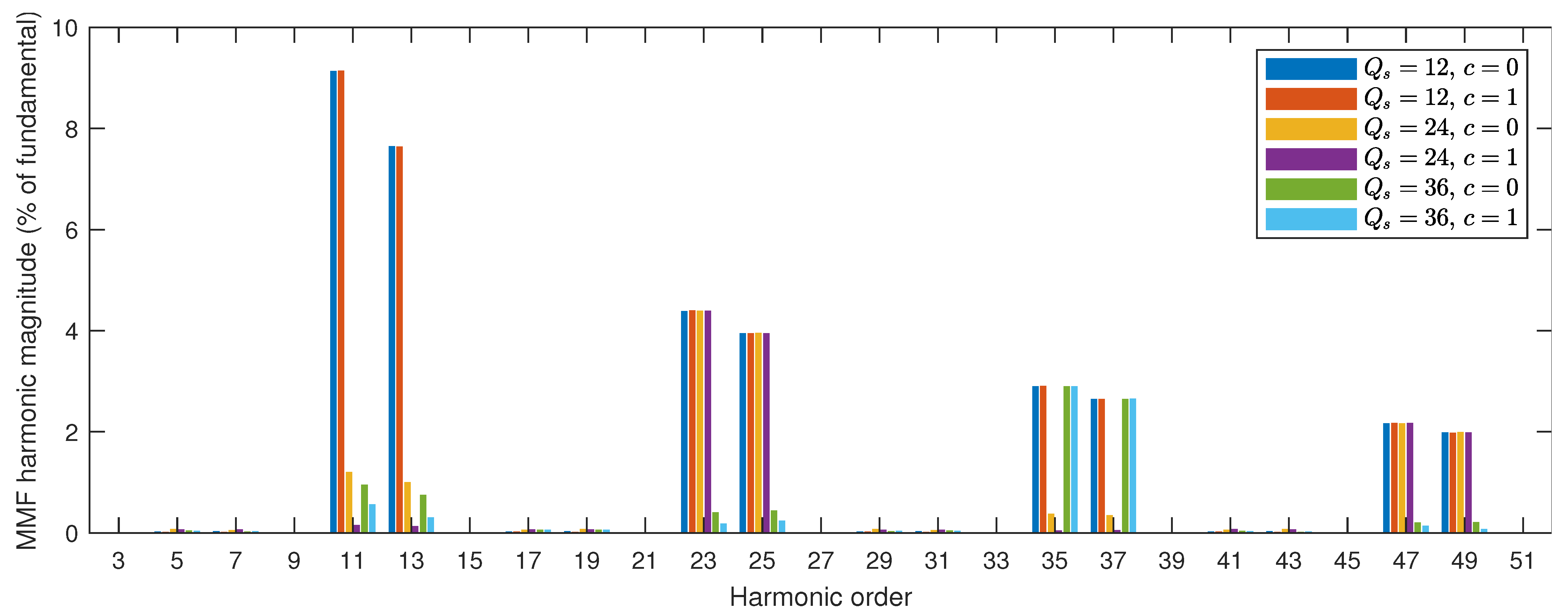
12) generate MMF spatial harmonics, as given in (
4), that rotate at angular frequencies
obtained according to (
5). The corresponding MMF harmonic magnitudes are shown in
Figure 4. As expected, the higher-order harmonics are the most pronounced in the 12-slot configurations (combinations (a), (b)), whereas the 36-slot configurations (combinations (e), (f)) have the lowest harmonic content. The pitch shortening is ineffective in the 12-slot configuration. The most pronounced MMF harmonics occur at slot frequencies, and these cannot be reduced regardless of the winding distribution.
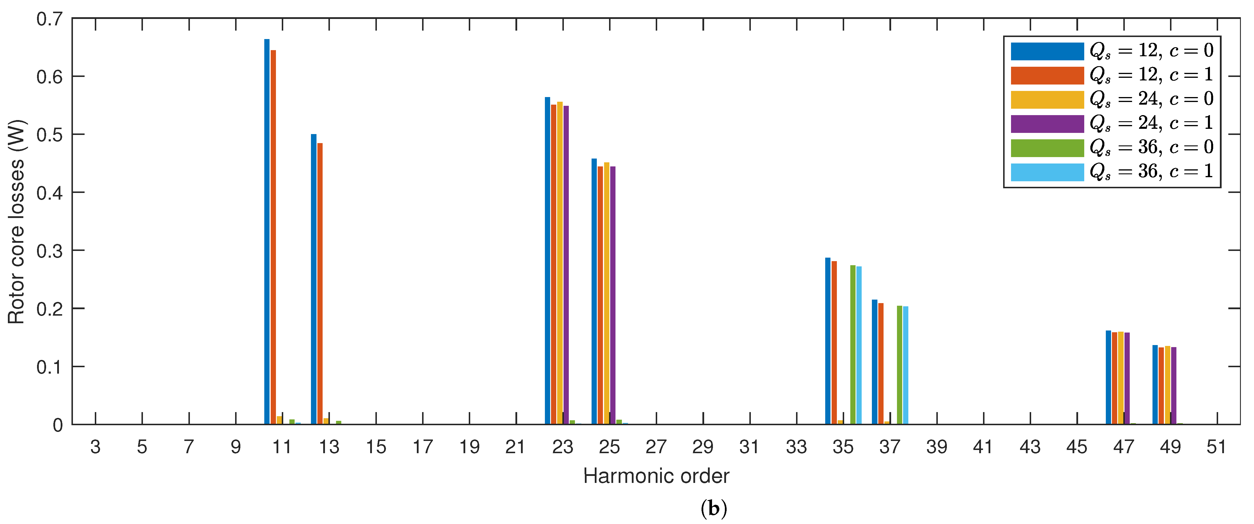
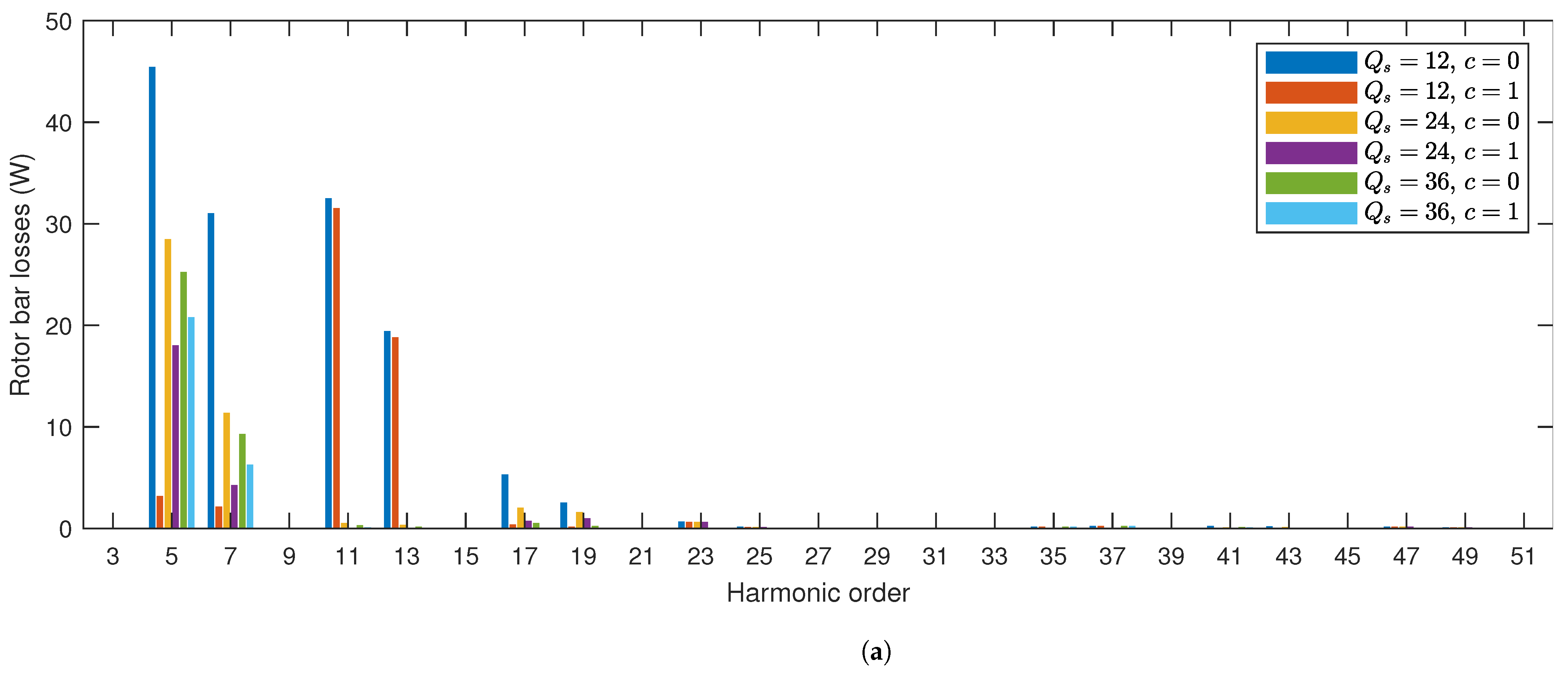
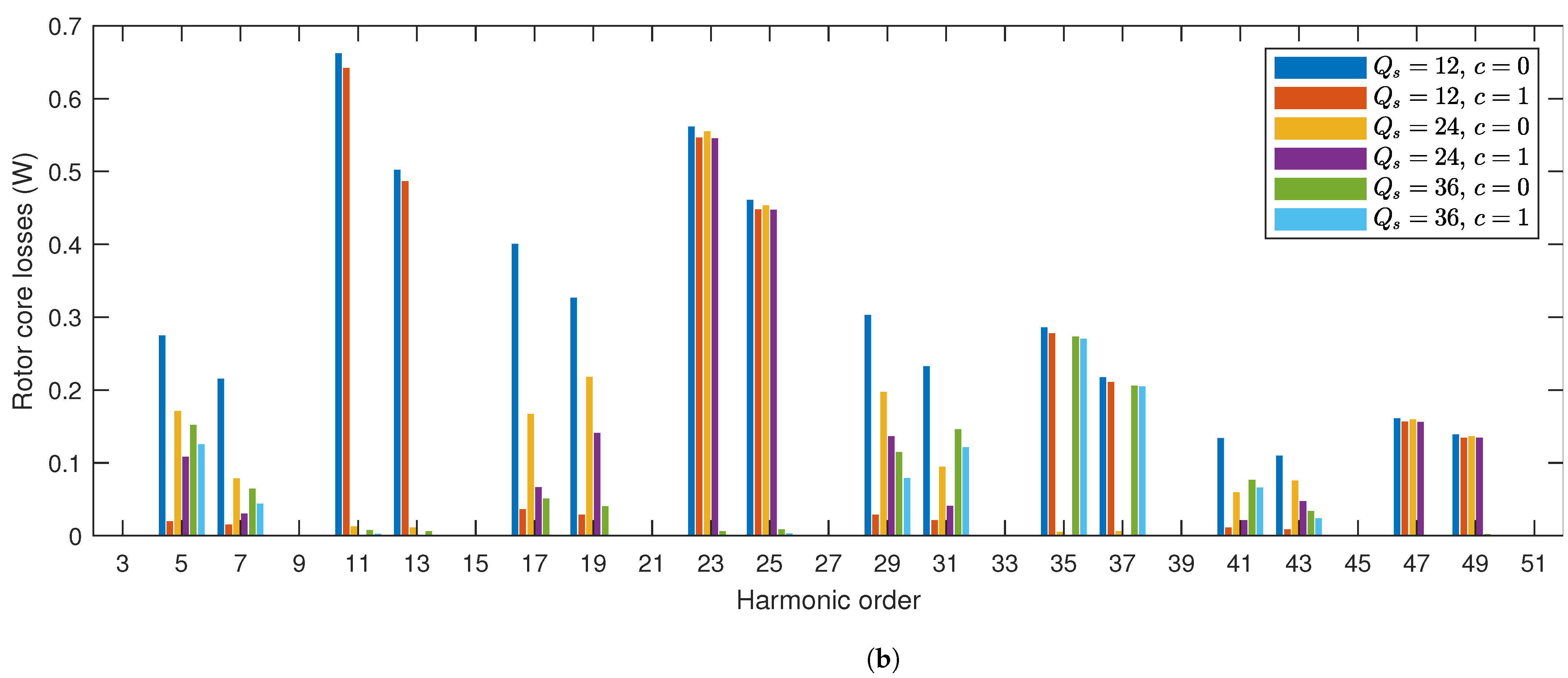
The losses in rotor bars and magnetic circuit determined for the MMF harmonics shown in
Figure 4 are displayed in
Figure 5. As visible in
Figure 5a, significant values of rotor bar losses exist only in the 12-slot configuration, where the 11th and 13th harmonics are dominant. The rotor core losses appear in all configurations, but their value gradually decreases as the harmonic order is increased. The physical interpretation of this reduction in rotor and core losses with an increase in spatial harmonic order will be given in
Section 5. The losses for harmonics up to the 51st order are summed and the total loss values are displayed in
Table 1.
4.2. Scenario (ii)
Phase currents consisting of combined fundamental frequency
and
components are given as:
Values of
and
are the same as in Scenario (i) and
. The value of
close to the rated current magnitude is selected to emphasize the effect of
current components. The MMF harmonic magnitudes corresponding to winding currents (
13) are shown in
Figure 6. The MMF harmonics contributed by the
plane current (11, 13, 23, 25, …) remain unchanged compared to Scenario (i) (see
Figure 4). However, with the introduction of
plane components, new spatial harmonics are introduced, most notably the 5th and 7th, as emphasized by magenta frames in
Figure 6. Note that the coil pitch shortening has a big impact on the magnitudes of MMF harmonics generated by
plane current components, especially in the 12-slot configuration. This is an interesting observation, as the shortened pitch has no influence on the MMF harmonic content of the 12-slot configuration when only
current components are present.
The losses in rotor bars and magnetic circuit determined for the MMF harmonics of
Figure 6 are displayed in
Figure 7. A significant increase in rotor bar losses caused by the 5th and 7th spatial harmonics can be noticed in
Figure 7a. Again, the bar losses are practically negligible for spatial harmonics above the 19th order. The core losses are increased for all harmonics corresponding to the
plane (spatial harmonics of order
), as visible in
Figure 7b. Unlike the bar losses, the core losses become even more pronounced for higher-order harmonics (e.g., the 17th/19th). The nature of these phenomena will be elaborated in
Section 5. The losses for harmonics up to the 51st order are summed and the total loss values are displayed in
Table 2. Due to the presence of the
current component and the corresponding MMF spatial harmonics, the values of losses have increased for all configurations compared to those given in
Table 1. This increase is the most pronounced in the 24 and 36-slot configurations, whereas the 12-slot configuration with a pitch shortening of 1 slot experiences a relatively low increase in rotor losses.
4.3. Scenario (iii)
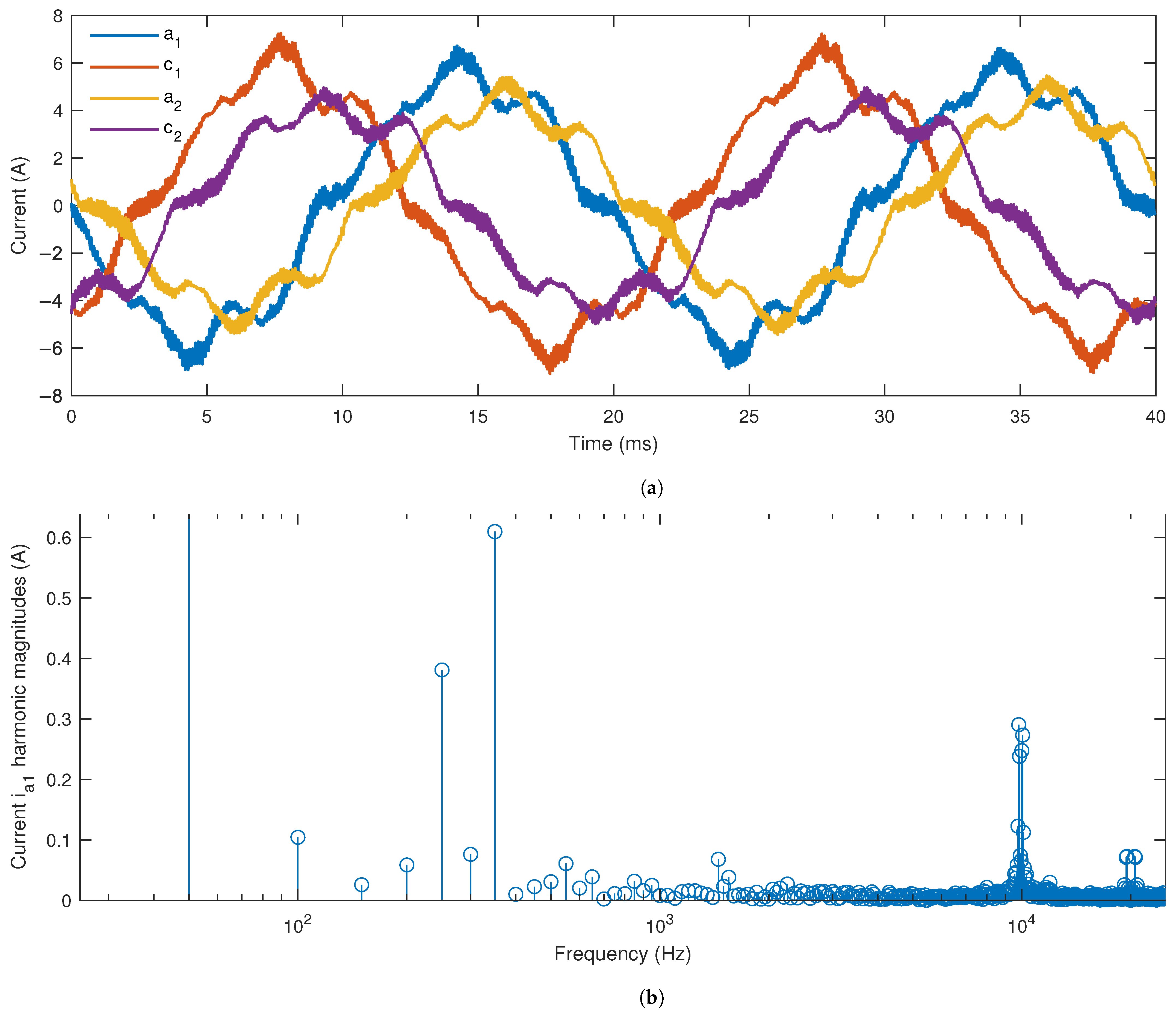
Experimentally obtained phase current waveforms used in this scenario are displayed in
Figure 8a. As the neutral points of the two three-phase windings are isolated, it was sufficient to measure four currents, whereas the remaining two currents are calculated. The 6PIM prototype described in the
Appendix A is supplied from a six-phase PWM inverter with a 10 kHz switching frequency and a 50 Hz fundamental frequency. The motor voltages contain only
plane components, however, the phase currents are not entirely symmetrical due to slight magnetic differences between the phase windings. The magnitude of
plane component of experimental currents is approximately 5 A. The spectrum of phase
currents is shown in
Figure 8b. The most pronounced low-order harmonics are the 5th and 7th, and they can be attributed mostly to saturation effects. High-order harmonics corresponding to current ripple are present around the switching frequency and its multiples.
MMF spatial harmonics magnitudes are determined for selected current harmonics according to (
4). For an arbitrary current harmonic
, the rotating angular frequency of an arbitrary spatial harmonic is determined from (
5) as:
where
is the fundamental frequency. The frequencies of rotor currents, i.e., the FEA simulation frequencies, are determined are then determined by substituting appropriate values into (
10).
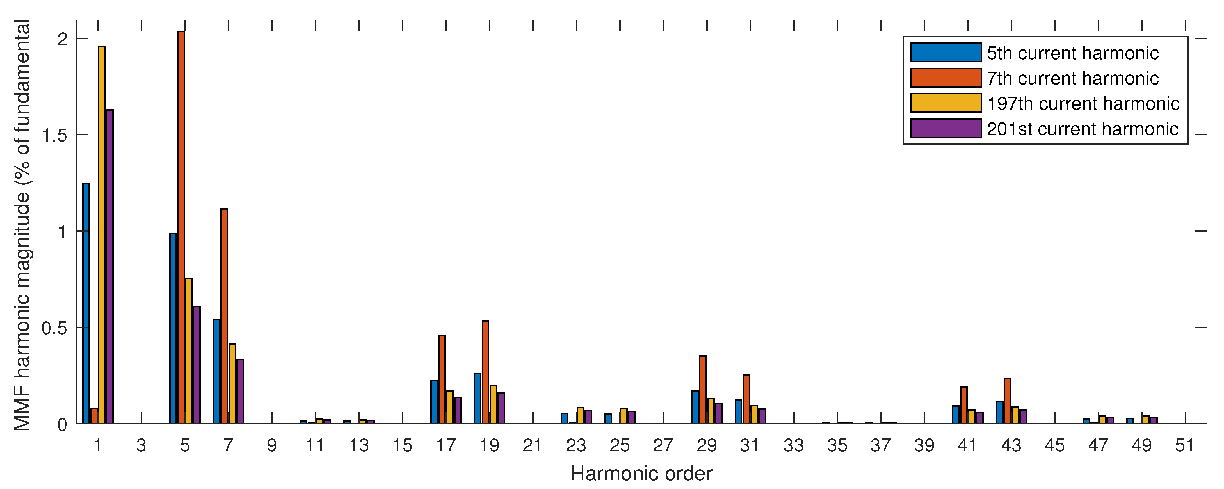
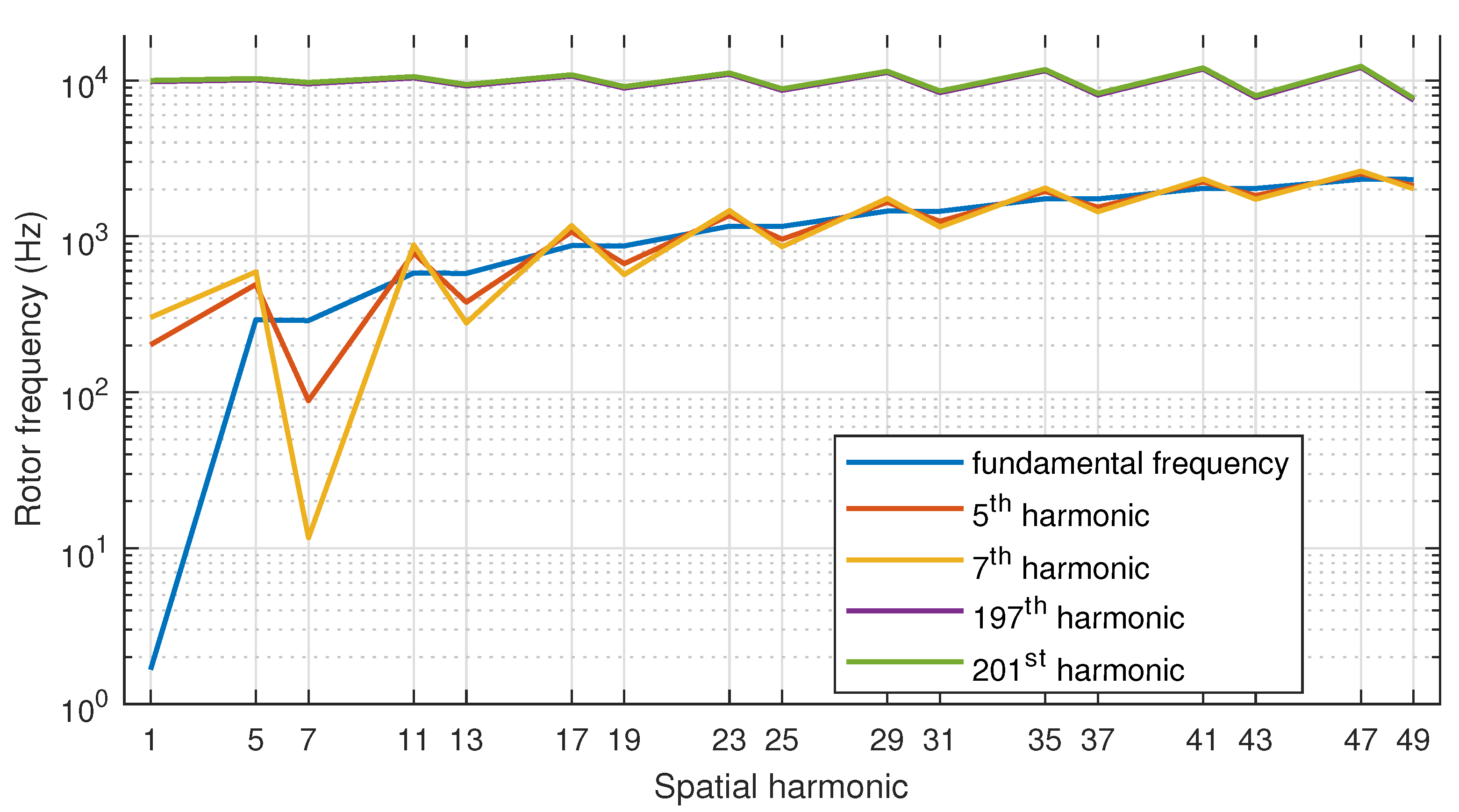
The rotor harmonic losses are calculated using the LC model for the selected current harmonics: 5th, 7th, 197th, and 201st. The goal is to illustrate the effect of both low-order and high-order harmonics on the rotor losses. The high-order harmonic components of the 197th and 201st order are highly pronounced due to their proximity to the switching frequency (see
Figure 8b). The values of rotor current frequencies for the selected current harmonics and analyzed MMF spatial harmonics are calculated according to (
10) and given in
Figure A2 in
Appendix B. Only the 24-slot full-pitch configuration (combination (c)) is analyzed, as the current waveforms correspond to this configuration. The MMF spatial harmonic magnitudes corresponding to the selected current electrical harmonics are shown in
Figure 9. Note that current harmonics contribute both to fundamental and high-order MMF harmonics. As stated previously, the fundamental spatial harmonics are mapped into the
plane, whereas the 5th and 7th harmonics are mapped into the
plane. Therefore, the non-fundamental current harmonics actually generate MMF harmonics in both the
and
plane. The rotor losses caused by fundamental spatial MMF harmonics generating by non-fundamental current harmonics are considered harmonic losses as well and will hence be included in the analysis.
The losses in rotor bars and magnetic circuit are determined for the MMF harmonics shown in
Figure 9, and their values are displayed in
Figure 10. As visible in
Figure 10a, the rotor bar losses are practically negligible for spatial harmonics above the 20th order, similarly to scenarios (i) and (ii). A substantial part of losses is contributed to the high-frequency components, specifically the 5th and 7th spatial harmonic. The high-frequency current components (197th and 201st harmonic) generate MMF harmonics of lower magnitude compared to their low-frequency counterparts (5th and 7th harmonic). However, the rotating frequency of MMF components generated by high-frequency currents is much higher, resulting in higher losses both in rotor bars and core. It is interesting to note that the rotor losses caused by the 7th MMF spatial harmonic generated by the 7th current harmonic are practically negligible, even though the magnitude of the corresponding MMF spatial harmonic has a relatively high value. This is due to the low rotating frequency of this MMF component as seen from the rotor (calculated according to (
10)), which can be observed in
Figure A2 in
Appendix B. To recollect, these rotating frequencies are equivalent to frequencies of induced currents in the rotor bars/core, i.e., to the simulation frequency for the given MMF component. It can be observed from
Figure A2 that the rotating frequencies of the 7th spatial MMF harmonic generated by the 5th and 7th current harmonics are relatively low (
and
, respectively), which explains the low losses generated by this MMF component. On the other hand, the rotor frequencies corresponding to the high-frequency current components are around 10 kHz regardless of the spatial harmonic order, leading to the high values of losses contributed by the high-frequency currents.
The total values of losses generated by each current harmonic are shown in
Table 3. As expected based on the results shown in the diagrams of
Figure 10, the current harmonics in the high-frequency region contribute the most to rotor losses, particularly the core losses.
5. Discussion and Conclusions
This section is intended to summarize the analysis results, provide their physical interpretation, and offer guidelines for minimizing the rotor harmonic losses. By examining the results presented in the previous section, the following observations can be made:
when only fundamental frequency current components are present (scenario (i)), the 12-slot configuration exhibits the highest rotor bar losses, whereas the bar losses of the 24 and 36-slot configurations are negligible;
rotor bar losses are negligible for spatial harmonics above the 19th order in all scenarios;
the winding pitch has very little influence on the MMF distribution and rotor harmonic losses in scenario (i)
the winding pitch has a significant influence on the MMF harmonic magnitudes and harmonic losses attributed to the current components in the plane in scenario (ii);
the presence of current components in the plane in scenario (ii) causes a significant increase in rotor harmonic losses compared to scenario (i);
the high-frequency components of experimentally obtained currents used in scenario (iii) cause a significant increase in losses in both the rotor bars and rotor core, most notably due to the 5th and 7th MMF spatial harmonics.
The listed observations will now be discussed to gain a better understanding of the behavior of 6PIM in terms of harmonic losses.
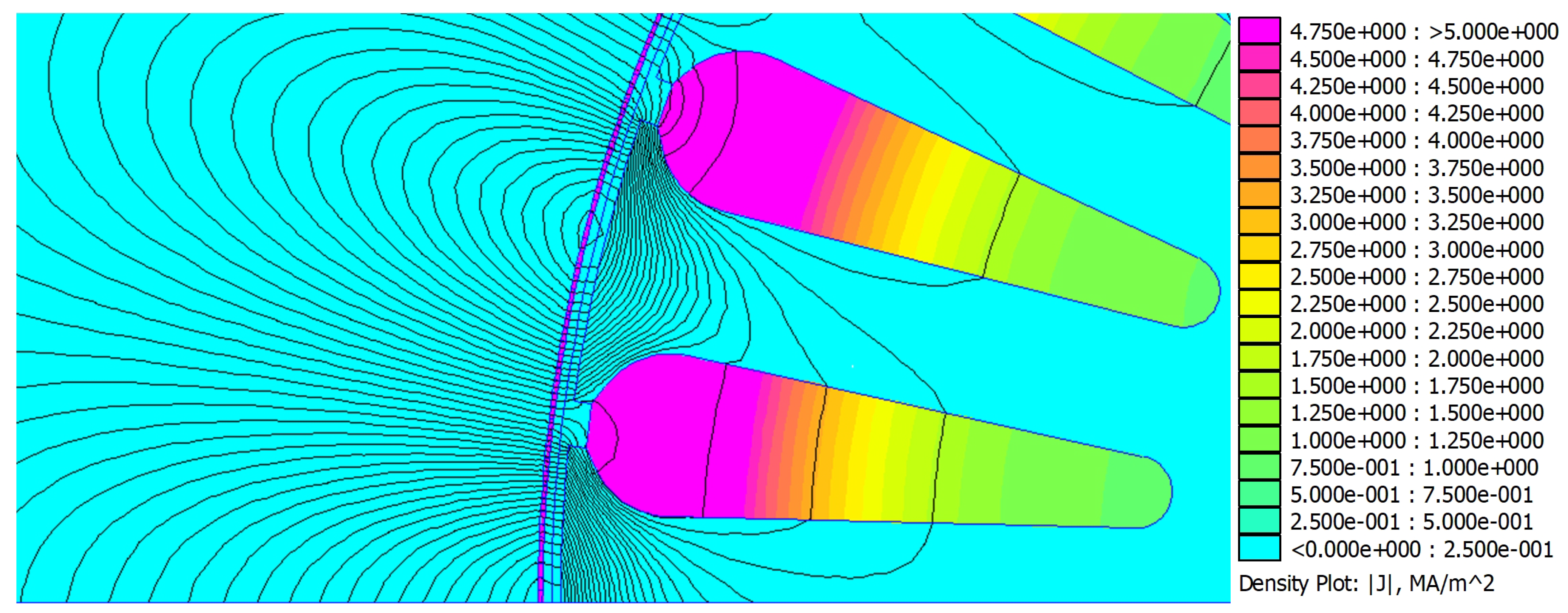
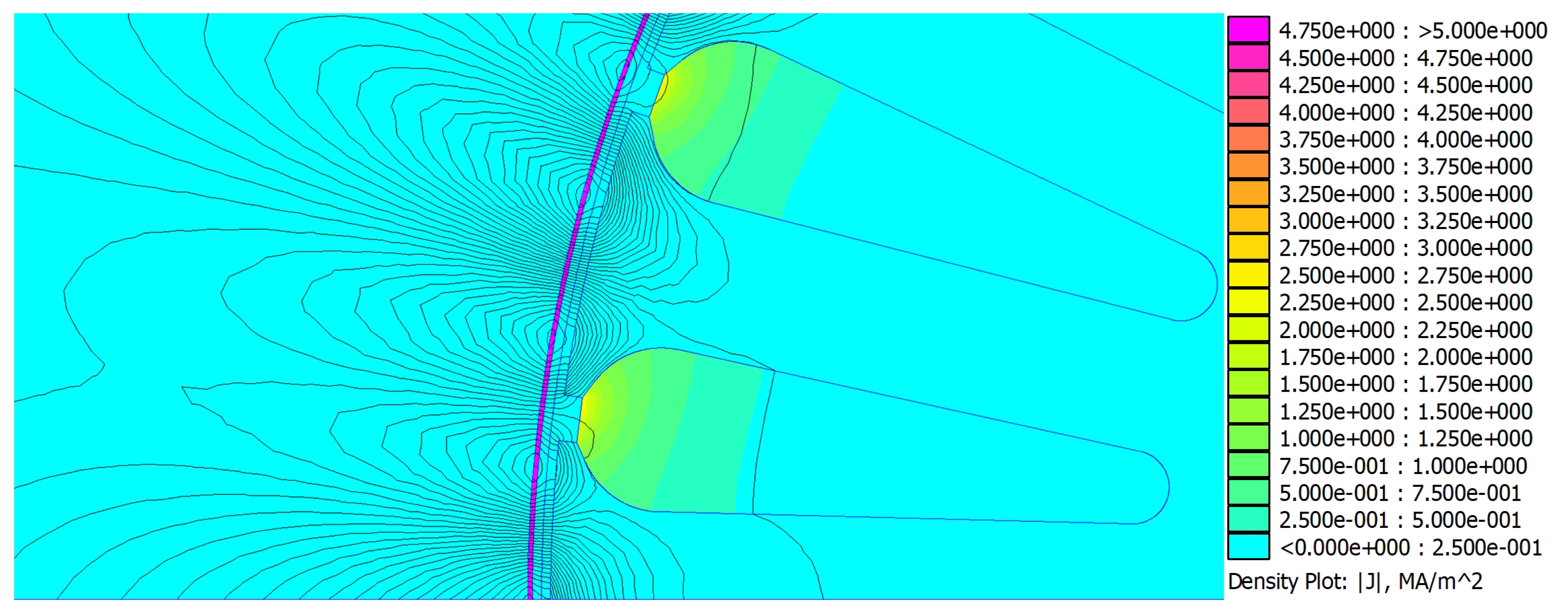
As the order of MMF spatial harmonics increases, the corresponding flux lines become shorter and penetrate a smaller part of the rotor volume. The dominant MMF spatial harmonics of the 12-slot configuration in scenario (i) are of the 11th and 13th order. On the other hand, the dominant spatial harmonics of the 24-slot and 36-slot configurations in scenario (i) are of the order 23/25 and 35/37, respectively. The flux produced by the MMF harmonics of the 12-slot configuration penetrates a larger portion of the rotor bars and core compared to the 24 and 36-slot configurations, which leads to higher induced currents and higher harmonic losses. This also explains the statement regarding low values of rotor bar losses corresponding to MMF spatial harmonics above the 19th order.
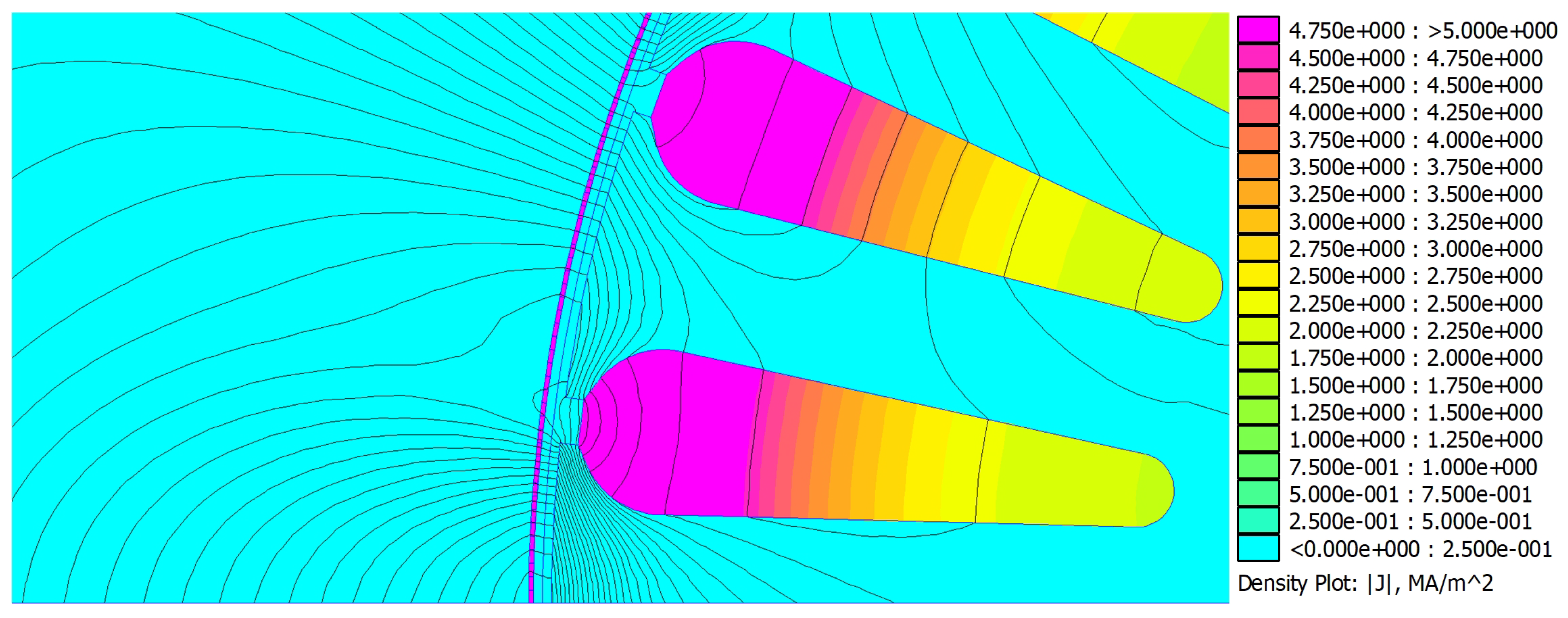
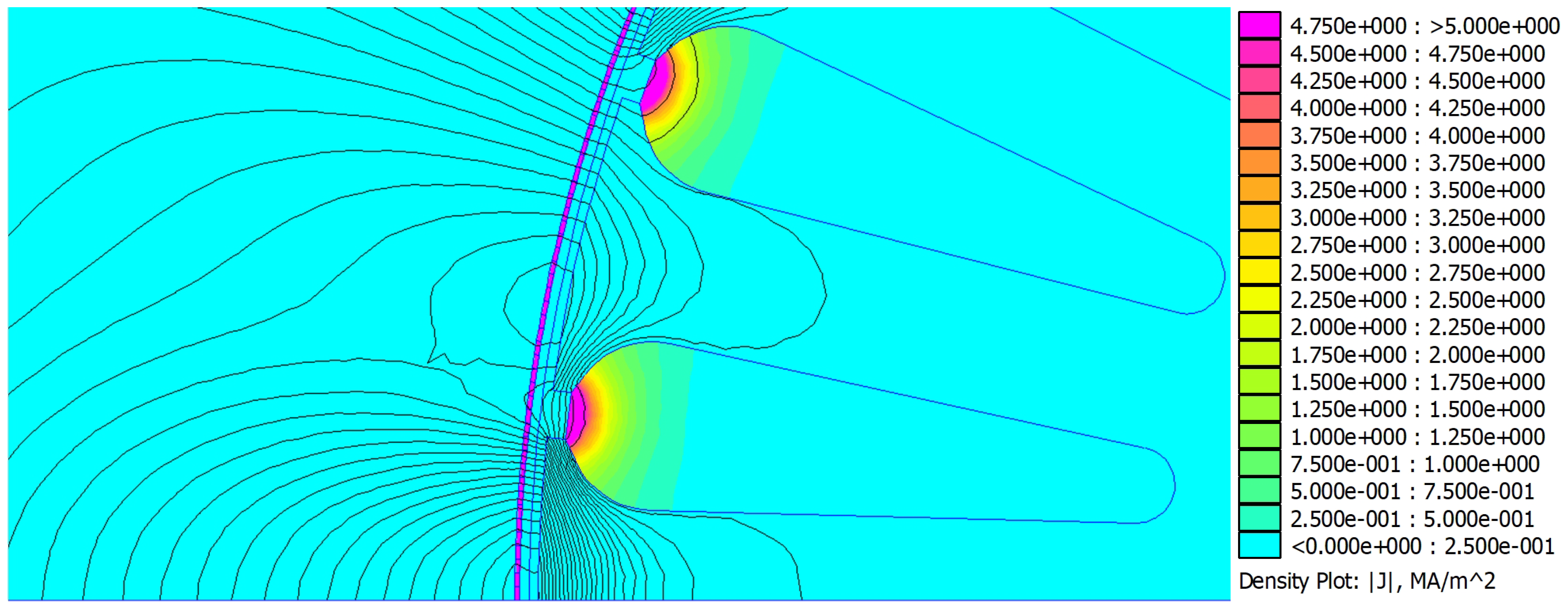
Figure A3 and
Figure A4 in
Appendix B illustrate the difference between the flux distribution and rotor current density of the 12-slot and 36-slot configurations. The displayed results correspond to dominant MMF harmonics in scenario (i) for each configuration.
The higher order harmonics related to the
plane current consist only of slot harmonics, which cannot be attenuated by means of winding distribution. On the other hand, the leakage inductance in the
plane is greatly affected by the winding pitch, as demonstrated in [
25]. The variations in
plane leakage inductance are actually a consequence of reduced MMF harmonics corresponding to the
plane, which explains the reduction of these harmonics due to short pitching observable in
Figure 6.
As stated in
Section 2.2, the current components in the
plane produce dominantly the 5th and 7th MMF spatial harmonics. With
current components at fundamental frequency, the frequencies of induced rotor currents are slightly lower than 300 Hz, as shown in
Figure A2 in
Appendix B. Additionally, the flux lines corresponding to these spatial harmonics penetrate a great portion of the rotor. Therefore, the losses associated with the
current components are distributed in a large volume, and the induced rotor currents are high due to the high frequency. To demonstrate this,
Figure A5 in
Appendix B displays the flux distribution and rotor current density corresponding to the 5th spatial harmonic in scenario (ii).
The high-frequency current components generate MMF harmonics which have rotating frequencies of around 10 kHz relative to the rotor (see
Figure A2). Therefore, the induced currents in rotor bars are expected to be high. Due to the low magnitudes of the high-frequency components, the corresponding MMF harmonics are much lower than those generated by low-frequency current components, as shown in
Figure 9. Still, the increase in harmonic losses caused by these components is not negligible, as can be observed from
Figure 10 and
Table 3. The major portion of losses caused by high-frequency current components is associated with the 5th and 7th spatial harmonic. This means that the high-order current harmonics contain components in the
plane, which increases the overall rotor harmonic losses. The flux density distribution and rotor current density corresponding to the 5th spatial MMF harmonic generated by the 197th current harmonic (scenario (iii)) are displayed in
Figure A6. Note that the current density is very high in a small rotor bar volume, which could lead to local overheating and consequential thermal damage.
The methodology presented in this paper enables calculation of rotor harmonic losses of a 6PIM for arbitrary current waveforms. Furthermore, the contribution of individual MMF spatial harmonics at arbitrary current frequencies can be determined. This provides a useful tool for a more advanced approach to stator winding design of the 6PIM in terms of loss minimization. The possibility of including plane current components in the harmonic loss calculation is very important, as post-fault operation is often required with multiphase machines. The possibility of including high-frequency (PWM) current components in the calculation allows the influence of the applied control algorithm and modulation technique on harmonic losses to be perceived and accounted for. The presented approach can serve as a foundation for new multiphase machine models with improved loss calculation accuracy, leading to better performance prediction in terms of efficiency and thermal calculations.


