Article

Running Experimental Research of a Cable-Driven Astronaut on-Orbit Physical Exercise Equipment

1
National Key Laboratory of Science and Technology on Advanced Composites in Special Environments, Harbin Institute of Technology, Harbin 150080, China
2
College of Mechanical and Electrical Engineering, Harbin Engineering University, Harbin 150001, China
3
College of Mechanical and Electronic Engineering, China University of Petroleum, Qingdao 266580, China
4
School of Mechanical Engineering, Northeast Electric Power University, Jilin 132012, China
*
Author to whom correspondence should be addressed.
Machines 2022, 10(5), 377; https://doi.org/10.3390/machines10050377
Submission received: 29 March 2022 / Revised: 28 April 2022 / Accepted: 13 May 2022 / Published: 16 May 2022
(This article belongs to the Section Bioengineering Technology)

Abstract

:
Manned spaceflight has already become an important approach to space science exploration, while long-term exposure to the microgravity environment will lead to severe health problems for astronauts, including bone loss, muscle atrophy, and cardiovascular function decline. In order to mitigate or eliminate those negative influences, this paper presents a cable-driven exercise equipment that can be applied in a microgravity environment to render multi-functional on-orbit physical exercise modes for astronauts. First, the structure of cable module and the configuration of the equipment were proposed. Second, a two-level controller was provided, including the cable tension distribution algorithm and tension controller of the cable module. A safety protection strategy was proposed to ensure the safety of the astronaut. Furthermore, simulation and running experiment studies of the equipment were conducted, the results demonstrate that the load force of the equipment could achieve a high-level accuracy, and the exercise status of the astronaut could be monitored and protected in the meantime. Therefore, physical exercises could be carried out by the assistance of the equipment to keep astronauts in good shape on-orbit.

1. Introduction

Outer space is the common wealth of mankind, and the exploration of the outer space is also the unremitting pursuit of mankind [1,2,3]. At present, the role of the space industry in the global overall development strategy is increasingly prominent, and the experimental research on space exploration is increasing at an incredible rate. Space exploration activities significantly enhance the progress of human civilization and social development [4]. With the progress of manned spaceflight technology and the completion of the space station, human space activities have been continually exploring deep outer space far from the low Earth orbit. However, the particularity of the space environment, such as the microgravity environment, radiation, and extreme temperature, has brought great challenges to the core of manned spaceflightl—astronauts [5,6]. Aerospace medicine problems have gradually become the main unfavorable factors restricting space exploration. The physical problems caused by entering space mainly include the following aspects: space motion sickness [7], also known as Space Adaptation Syndrome; the decline of motor coordination [8]; a reduced number of red blood cells in blood [9], anemia [10]; and the redistribution of body fluids causes a series of physiological changes [11]; meanwhile, the microgravity environment causes the decline of cardiovascular function [12], osteoporosis [13], muscle atrophy [14], immune function [15], and brain function [16]. Aerospace medical studies illustrate that the health level of astronauts in space can be maintained with the help of lower body negative pressure technology, reasonable physical exercise [17], and medicine [18]. However, astronauts can not carry out physical exercise without the assistance of other devices in a microgravity environment. Thus, a lot of exercise equipment has been developed to provide astronauts requiring exercise load characteristics. Even so, the volume and mass constraints of the spacecraft provide challenges for the development of effective exercise countermeasures [19].
In early 2009, interim Resistive Exercise Device (iRED) [20] had been replaced by Advanced Resistive Exercise Device (ARED) [21] to assist astronauts in conducting deep squats, bench presses and heel raise exercises on the International Space Station (ISS). The ARED uses vacuum cylinders to simulate free weights for resistive exercise. Although a variety of exercises could be carried out by ARED, the volume of it is bulky, the weight of it is heavy, and the only type of exercise that it can provide is strength training, while aerobic exercise is not included.
A Treadmill with Vibration Isolation and Stabilization (TVIS) had been installed and entered service on the ISS in 2000 [22], which is almost the same as the spinning bike in a fitness room. A similar running machine was also equipped at Tiangong-2. However, the TVIS and the running machine at Tiangong-2 only provide one function, which is running. Falling and injury risks are also an issue for astronauts since a moment to lean their body forward or backward can be easily generated by fixing the load point at the waist [23].
X-1 is a lower-limb exoskeleton robot [24,25], jointly developed by NASA and IHMC, and is used for astronauts in space exercises. X-1 exerts a load on the astronaut’s body via a servo motor which will slow down the loss of bone and muscle atrophy. However, the exoskeleton system is not economical and inconvenient to setup or operate since the exoskeleton should adjust to different individual lower-limb lengths. Furthermore, the rigid connections with the astronauts also raise the injury risk.
The future use of exercise for human space mission should have enabled the comprehensive adoption of terrestrial exercise training concepts, including continuous and interval-type aerobic exercise and high-intensity, and multi-set/rep resistance training [26,27]. However, the existing space exercise devices for astronauts demonstrate several flaws: (1) Sole function; (2) Large space occupation; (3) High cost; and (4) Complicated operational process.
In order to overcome these drawbacks, this paper proposes a cable-driven Astronaut on-orbit Physical Exercise Equipment (CAPE). The cable-driven systems have a lot of advantages compared with the rigid systems, such as low manufacturing cost, large workspace, low inertia, light-weight, and high velocity. Benefiting from these outcomes, this type of drive mode has been widely applied in rehabilitation areas. SK Agrawal proposes a cable-driven exoskeleton for gait rehabilitation in lightweight and constraint-free architecture [28]. Robert Riener presents a cable-driven, soft, flexible, and lightweight wearable robot for lower-limbs (Myosuit) [29] and shoulders (Myoshirt) [30] in regaining the patient’s ability to move. Kyu-Jin Cho develops a soft wearable cable-driven robot for the hand that helps people with spinal cord injuries for assisting in daily life [31]. Conor Walsh proposes a cable-driven lightweight exosuit that is able to reduce the metabolic rate for running and walking [32]. These devices are used for actively assisting people with impairment to accomplish movement in activities of daily living (ADLs) or augmenting the capabilities of healthy individuals. However, the CAPE is a device that passively follows the movement of the astronaut and provides required exercise resistance which can be interpreted as a load simulator. Therefore, compared with the aforementioned cable-driven systems, we are more concerned about the force control performance of the CAPE and pay less attention to the position control performance. The CAPE has a number of advantages: (1) Multi-functional; (2) Small space occupation; (3) Low cost; and (4) User-friendly. This paper is organized as follows: an overview of the CAPE was presented in Section 2, including the cable module and system configuration; and a two-level controller and safety protection strategy were described in Section 3. In Section 4, to base a foundation for a running exercise experiment, a simulation study simulation was conducted to verify the validity of the two-level controller and safety protection strategy; then, the hardware-in-loop experiment was carried out, while the conclusion was provided in Section 5.

2. Cable-Driven On-Orbit Astronaut Physical Exercise Equipment (CAPE)
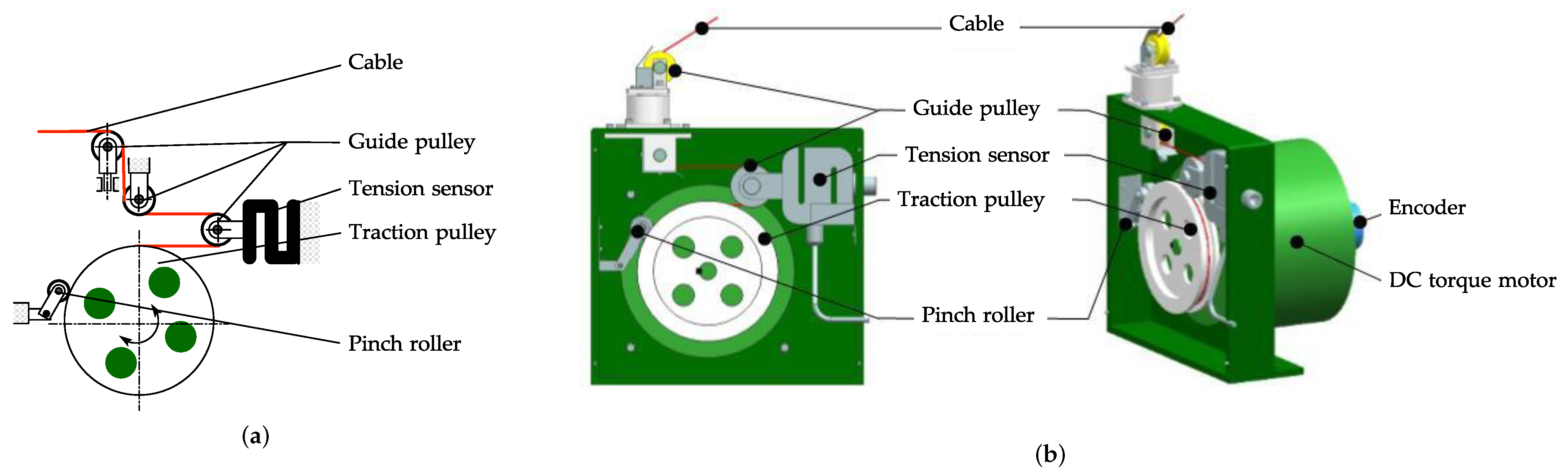
2.1. Cable Module

The cable module structure is shown in Figure 1, where Figure 1a is the schematic diagram of the cable module, and Figure 1b is the three-dimensional drawing of cable module. It is composed of a permanent magnet DC torque motor, encoder, traction pulley, pinch roller, guide pulley, tension sensor, and cable. The function of the pinch roller is to restrict the cable around the traction wheel to prevent skipping. The radius of the cable traction wheel is 0.06 m. The permanent magnet DC torque motor 160LYX06 is adopted, the maximum tension of the cable module is 500 N , and the maximum speed of the cable module is 0.75 m / s .

2.2. Configuration of CAPE

The general configuration of a Cable-driven Astronaut on-orbit Physical Exercise equipment (CAPE) is shown in Figure 2. The CAPE is composed of four load cable modules in green, two protection cable modules in orange, a treadmill, a bench press bar, a bench and two guide pulleys. In this arrangement, the CAPE has the following characteristics:
(1)
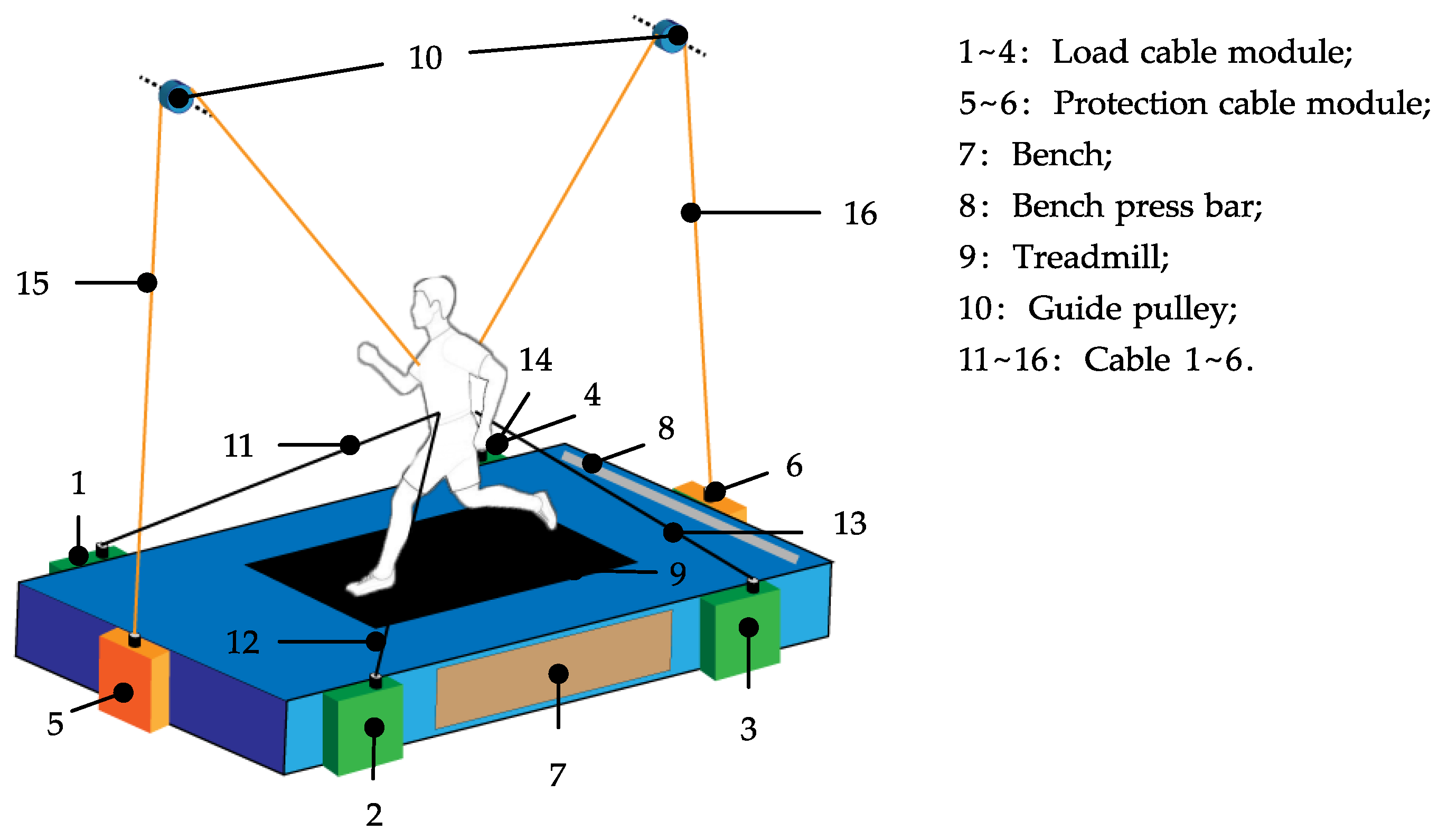
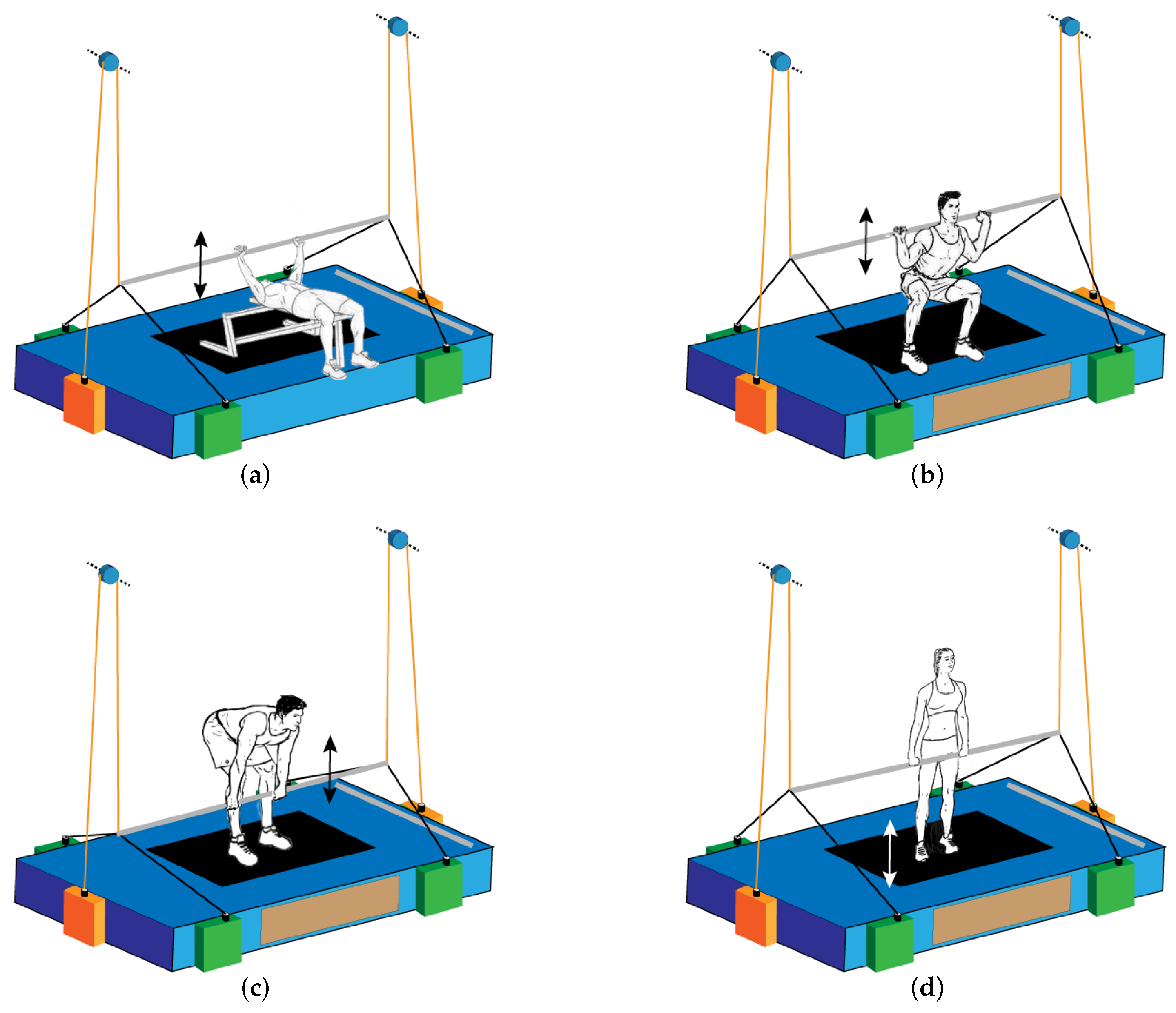
CAPE provides astronauts with a variety of exercise modes, realizing high efficiency without increasing the cost of the equipment. As shown in Figure 2 and Figure 3, with the assistance of CAPE, astronauts are able to carry out bench press, deep squat, deadlift, heel raise, and running exercise. In which running is aerobic exercise, while others are weight-exercises.
(2)
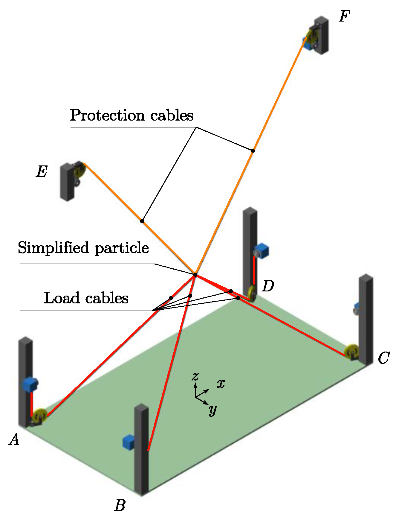
The CAPE can be easily set up by the help of the carabiners at the each end of the cables. Compared with the rigid connections with the human body of most of the existing exercise devices in space, the type of cable-driven will significantly reduce the injury risk. Furthermore, to ensure the safety of the astronaut, CAPE provides a safety protection strategy. As presented in Figure 2, the four green cable modules realize the load force during exercises, and two orange cable modules are responsible for the safety monitoring and the protection of astronauts. Normally, the two orange cable modules follow the movement of astronauts passively, while in some cases to avoid accidents or instability, these two modules collaborate with the other four green cable modules to complete safety protection actions, which is described in Section 3.
(3)
Modular design is adopted to develop the cable module, and the cable modules could be hidden in the floor of the space station. Several advantages are brought by this kind of modular design and arrangement: economical in cost; easy to replace, maintain, and repair; in addition, when the CAPE is inactive, the cable can be coiled on the traction pulley to occupy less space and improve the utilization rate of space, which is significant for the narrow space capsule, and provides an orderly living environment for astronauts.

3. Two-Level Controller and Safety Protection Strategy of CAPE

3.1. Two-Level Controller

The two-level controller consists of a cable tension distribution algorithm and a force controller of the cable module. The tensions of each cable corresponding to the particular load position could be calculated by the tension distribution algorithm. It also enhances the stability of the system and guarantees each cable to stay in a tight state. Force controller realizes a high-level accuracy of each cable tension to improve the system load precision.

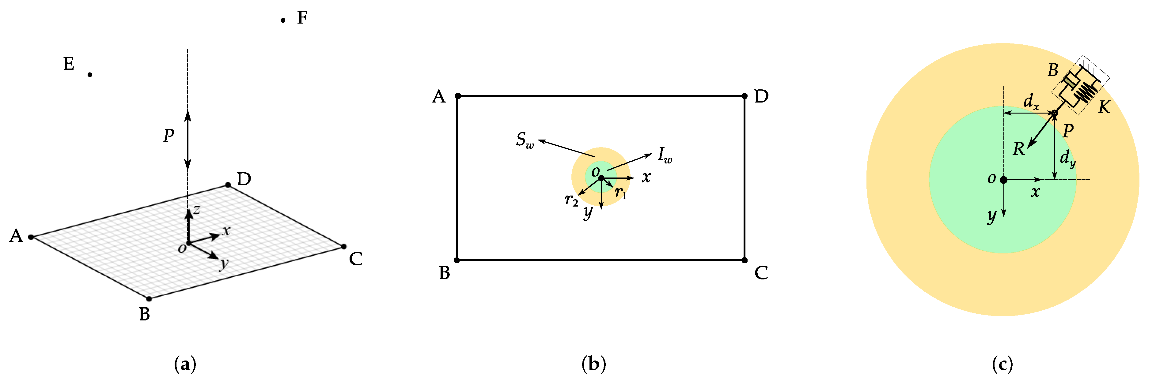
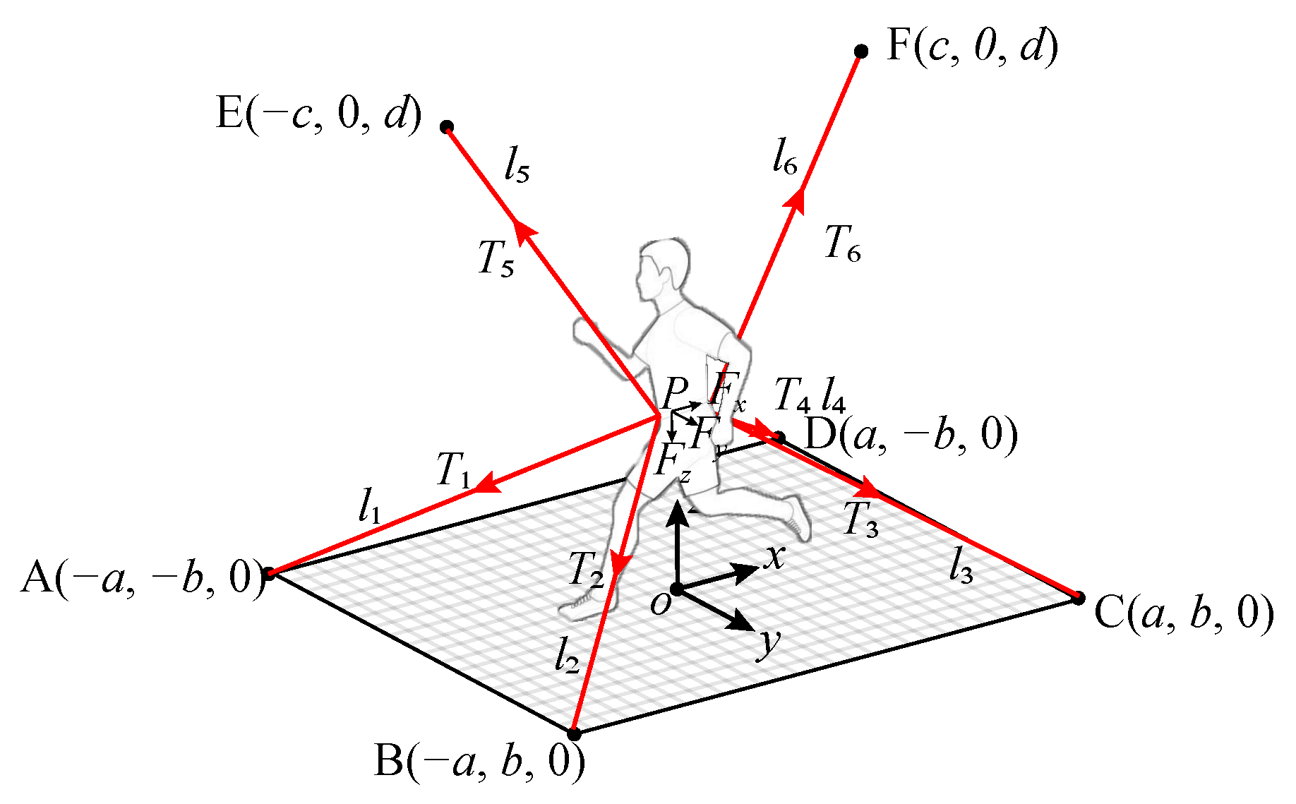
3.1.1. Cable Tension Distribution Algorithm for Running Exercise

The force analysis diagram presents in Figure 4. A, B, C, and D are the points that the four load cables come out from the load modules. E and F are the positions of the two guide pulleys, and the two protection cables that come out from the protection cable modules will pass those two guide pulleys. The Cartesian coordinate system o- x y z is established at the center of the equipment base. The coordinates of each point are A ( a , b , 0 ) , B ( a , b , 0 ) , C ( a , b , 0 ) , D ( a , b , 0 ) , E ( c , 0 , d ) , and F ( c , 0 , d ) , in which a = c = 0.75 m , b = 0.3 m , d = 1.8 m . The tension of each cable is T i ( i = 1 6 ) . The length of each cable is L i ( i = 1 6 ) . The load point is near the pelvis, which can be approximately regarded as the point P ( x , y , z ) where the six cables intersect in the human body. The components of the resultant force at the load point in x, y, and z directions are F x , F y , and F z , respectively. The mathematical relationship among the coordinate of load point P, the length of each cable, and the coordinates of points A to F are presented in Equation (1).
( a + x ) 2 + ( b + y ) 2 + z 2 = l 1 2 ( a + x ) 2 + ( b y ) 2 + z 2 = l 2 2 ( a x ) 2 + ( b y ) 2 + z 2 = l 3 2 ( a x ) 2 + ( b + y ) 2 + z 2 = l 4 2 ( a + x ) 2 + y 2 + ( z d ) 2 = l 5 2 ( a x ) 2 + y 2 + ( z d ) 2 = l 6 2
The coordinates of load point P can be obtained by any three equations in Equation (1). Thus, the top 3 equations are taken to solve the coordinate, and the results are as shown in Equation (2).
x = l 2 2 l 3 2 4 a y = l 1 2 l 2 2 4 b z = 1 2 a b 4 a 4 b 2 4 a 2 b 4 + 2 a 2 b 2 l 1 2 + 2 a 2 b 2 l 3 2 a 2 l 1 4 + a 2 l 2 4 + b 2 l 2 4 + b 2 l 3 4 4 + a 2 l 1 2 l 2 2 + b 2 l 2 2 l 3 2 2 1 2
In order to mimic the force characteristics of running exercise under a gravity environment, the expected load force in x, y, and z directions should be set as the form of ( 0 N , 0 N , F l o a d ) . Therefore, according to the geometric principle, the mathematical relationship between the expected load force and the resultant force at the load point P generated by the four load cables can be demonstrated in Equation (3):
x + a l 1 T 1 + x + a l 2 T 2 + x a l 3 T 3 + x a l 4 T 4 = 0 y + b l 1 T 1 + y b l 2 T 2 + y b l 3 T 3 + y + b l 4 T 4 = 0 z l 1 T 1 + z l 2 T 2 + z l 3 T 3 + z l 4 T 4 = F l o a d
Equation (3) can be rewritten as H T = W , where T = [ T 1 , T 2 , T 3 , T 4 ] T is the vector of cable tension, H R 3 3 × 4 is the structural matrix, W is the expected load force. The equations are nonhomogeneous linear system of equations, thus the form of its solution is the combination of its particular solution and the general solution of the corresponding homogeneous linear system of equations. The minimum norm least-square solution is taken as a particular solution, as shown in Equation (4), where H + = H T ( H H T ) 1 . The general solution of the corresponding homogeneous linear system of equation H T = 0 is T h , as shown in Equation (5), where N u l l ( H ) = N 1 , N 2 , N 3 , N 4 is the one-dimensional null space basis of the structural matrix, and λ is the coefficient; therefore, the general solution of Equation (3) can be written as Equation (6):
T s = [ T 1 s , T 2 s , T 3 s , T 4 s ] T = H + W
T h = [ T 1 h , T 2 h , T 3 h , T 4 h ] T = λ N u l l H
T = T s + T h = H + W + λ N u l l H
The cable tension can be generated within the driving capacity range of the cable module by a reasonable selection of λ . Therefore, λ is the vital factor to improve the force condition of the system. T max = [ T 1 max , T 2 max , T 3 max , T 4 max ] T is the maximum tension that could be produced by the cable module. T min = [ T 1 min , T 2 min , T 3 min , T 4 min ] T is the minimum tension to ensure each cable stay in a tight state when assisting astronauts to carry out exercises, thus T should meet the requirement of Equation (7):
T min T T max
Equation (8) can be obtained by substituting Equation (6) into Equation (7):
T min T s λ N u l l H T max T s
Therefore, the range of the possible value of λ can be written as Equation (9):
λ min λ λ max
where
λ min = max 1 i 4 min 1 i 4 T i min T i s / N i , T i max T i s / N i λ max = min 1 i 4 max 1 i 4 T i min T i s / N i , T i max T i s / N i
Thus, the cable tension distribution problem has been converted to an optimization problem, which is shown in Equation (10). F λ is the objective function; in this case, we select the variance among the four load cable tensions as the optimization goal, which is shown in Equation (11). The variance is one of the critical attributes to measure the stability of the CAPE, the smaller it is, the fewer differences of all cable tensions, and the more stable the system is. It is described as the sum of the square of the difference between each cable tension and E ( T ) . E ( T ) is the mean value of the four cable tensions. Thus, the cable tension distribution algorithm can be interpreted as to select reasonable λ to make the F λ obtain the minimum value:
min F λ s . t . HT = W λ min λ λ max
F λ = 1 4 i = 1 4 T i E T 2 = ξ 1 λ 2 + ξ 2 λ + ξ 3
where T i = T i s + λ N i , E T = i = 1 4 T i / 4 , ξ 1 = Q / 4 N 2 / 16 , ξ 2 = L N / 8 , ξ 3 = M / 4 L 2 / 16 , and the L, M, N, and Q are shown as in Equation (12):
L = T 1 s + T 2 s + T 3 s + T 4 s M = T 1 s 2 + T 2 s 2 + T 3 s 2 + T 4 s 2 N = N 1 + N 2 + N 3 + N 4 Q = N 1 2 + N 2 2 + N 3 2 + N 4 2
Thus, ξ 1 can be simplified as Equation (13).
ξ 1 = N 1 N 2 2 + N 1 N 3 2 + N 1 N 4 2 + N 2 N 3 2 + N 2 N 4 2 + N 3 N 4 2 16
Obviously, the value of ξ 1 is a non-negative number. Then, the final value of λ written as λ * can be determined by the discussion of the value of ξ 1 :
(1)
If ξ 1 > 0 , the objective function F ( λ ) obtains the minimum value when λ = ξ 2 / 2 ξ 1 ; then, there are three cases:
λ * = λ min if λ < λ min , ξ 2 / 2 ξ 1 if λ min λ λ max , λ max if λ > λ max .
(2)
If ξ 1 = 0 , the objective function F ( λ ) can be written as F ( λ ) = ξ 2 λ + ξ 3 ; then, there are three cases:
λ * = λ min if ξ 2 > 0 , λ max if ξ 2 < 0 , Not Applicable if ξ 2 = 0 .

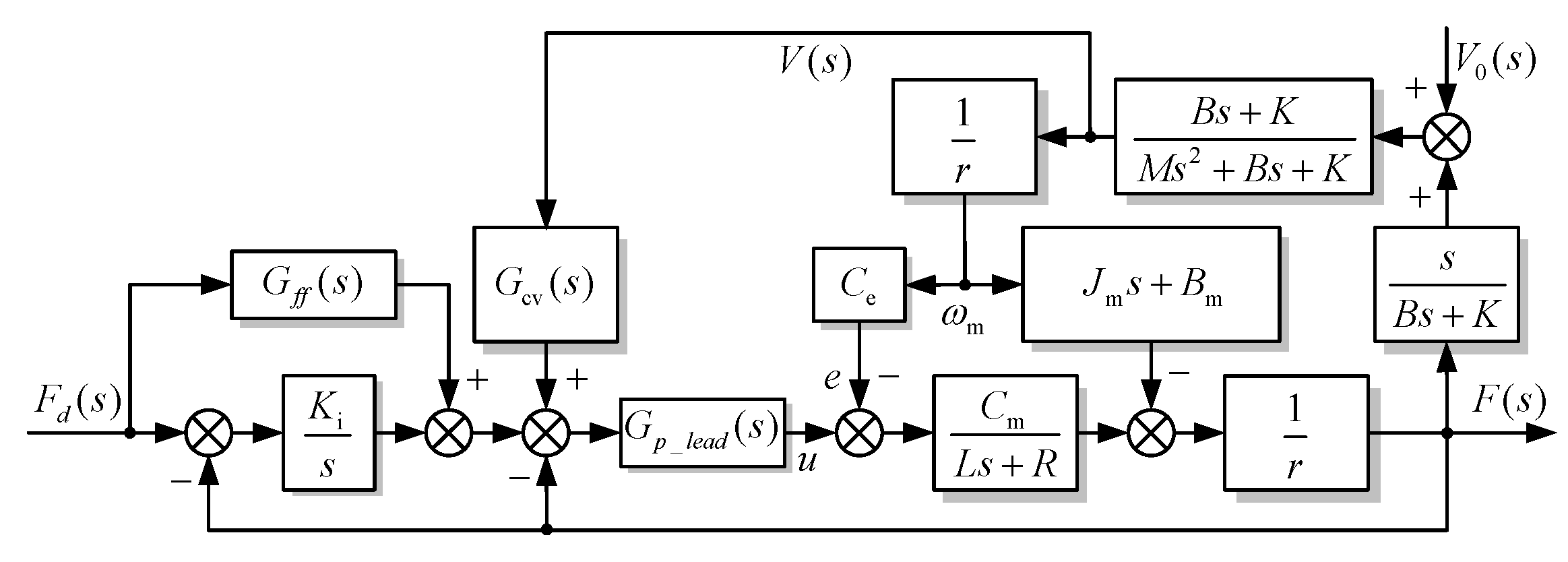
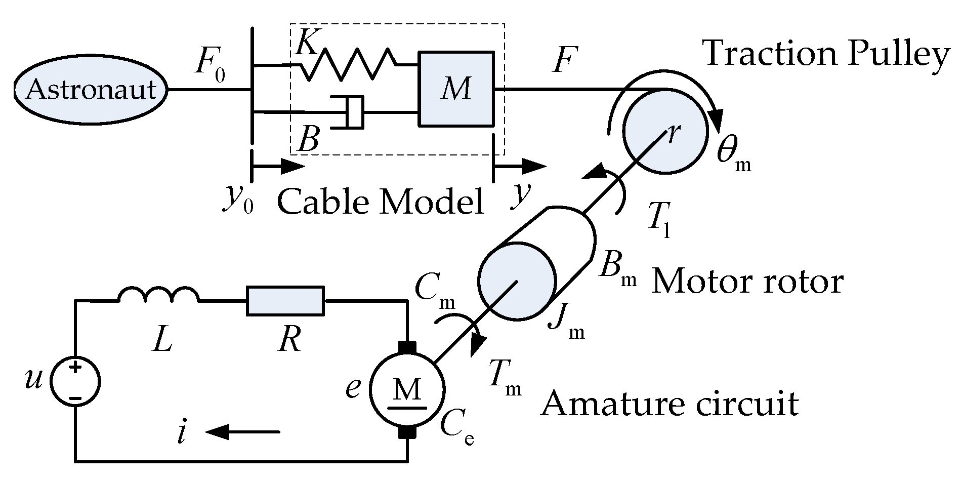
3.1.2. Tension Controller of Cable Module

In order to exert a desired load force on the astronaut’s body, the cable will passively follow the movement of astronaut when carrying out exercise, thus the cable will be set in an uncertain motion, and it should be considered as a disturbance input to the cable module. The mechanism diagram of cable module considering the movement of the astronaut is presented in Figure 5, in which u is input voltage of DC torque motor, y 0 is the displacement of the cable, L represents the DC torque motor inductance, R denotes the resistance of the DC torque motor, r stands for the radius of traction pulley, J m is the total inertia of traction pulley and DC torque motor rotor, B m stands for the motor damping coefficient, C m is the torque constant of DC torque motor, C e is the back-EMF constant of the DC torque motor, M is the mass of cable, B is the damping coefficient of the cable, and K is the stiffness constant of the cable, and T is the output tension of the cable module. The mathematical model of the cable module is shown in Equation (16).
T ( s ) = M 1 ( s ) u ( s ) M 2 ( s ) V 0 ( s )
where V 0 ( S ) = s Y ( s ) , M 1 is the forward transfer function, in which T is taken as the output and u is taken as the input. M 2 is the disturbance transfer function, in which T is taken as the output and V 0 is taken as the input. M 1 and M 2 are presented in Equations (17) and (18), respectively:
M 1 = C m r ( M s 2 + B s + K ) J e L s 3 + ( B e L + J e R ) s 2 + ( B e R + C m C e + K L r 2 ) s + K R r 2
M 2 = ( B s + K ) [ J M L s 2 + ( B m L + J m R ) s + B m R + C m C e ] J e L s 3 + ( B e L + J e R ) s 2 + ( B e R + C m C e + K L r 2 ) s + K R r 2
The tension controller of the cable module is presented in Figure 6. The forward channel compensator consists of an integral link, a local negative feedback link G p l e a d ( s ) , which is shown in Equation (19), and a feed-forward link G f f ( s ) . The disturbance compensator G c v ( s ) is designed based on the structure invariance principle as shown in Equation (20):
G p l e a d ( s ) = K a s 2 ω a n 2 + 2 ξ a n s ω a n + 1 s 2 ω a d 2 + 2 ξ a d s ω a d + 1
G c v ( s ) = M 2 ( s ) G p l e a d ( s ) M 1 ( s )

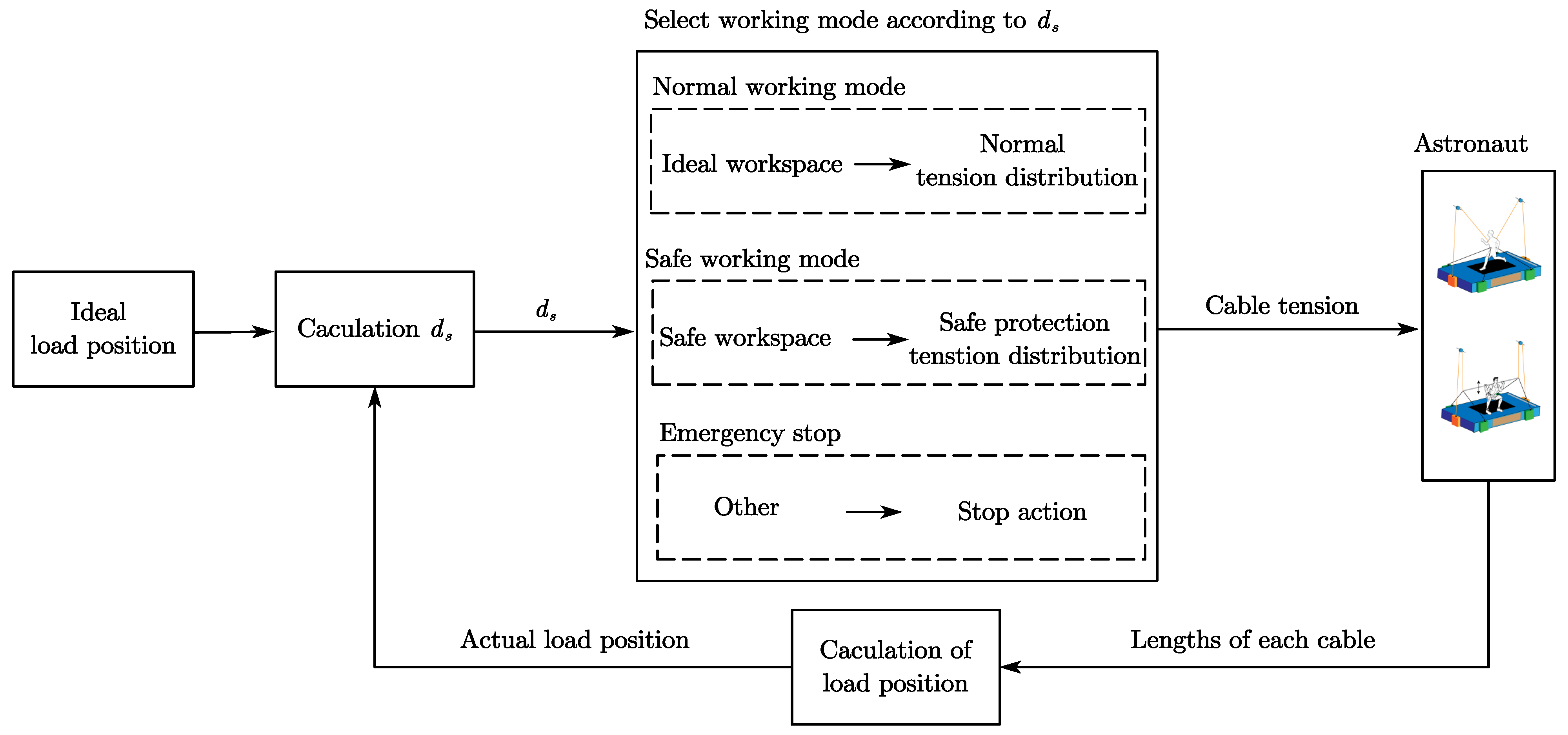
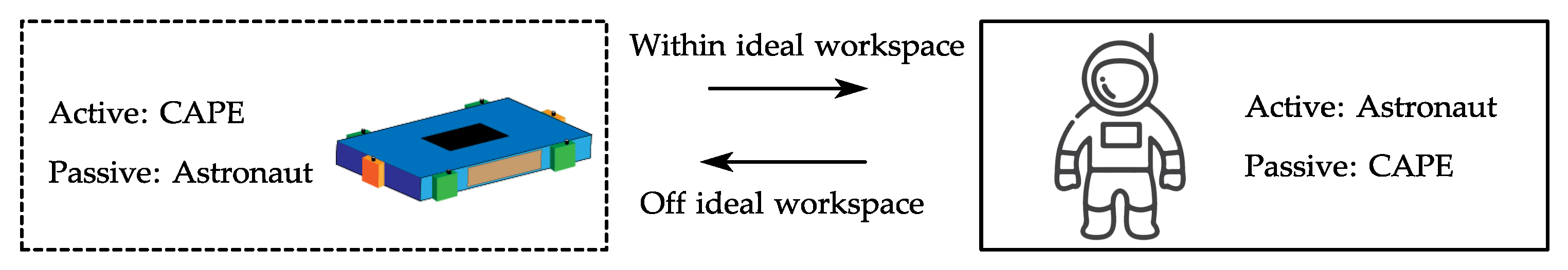
3.2. Safety Protection Strategy

As shown in Figure 7a, in running exercise, the projection of the ideal load point P on the base of the equipment is at the center o. The ideal track of it should be a reciprocating movement along the z direction. However, in the actual exercise process, the loading point P usually moves stochastically.
According to the projection of the distance d s between the load point and the z axis, as shown in Figure 8, the running exercise is divided into three working conditions: normal working mode, the offset is small, and the load point P is within the ideal workspace I w , which is defined as the green circle area with the radius of r 1 in Figure 7b; Safe working mode, the load point P works in the safe workspace S w which is the yellow ring area in Figure 7b, the radius of the external circle is r 2 ; in this condition, the load point will be pulled back to the ideal workspace by the cooperation between the load cables and protection cables; Emergency stop mode, the offset of the load point P exceeds the safe workspace—the astronaut might fall or be injured, so emergency stop action should be taken. In fact, the safety protection policy is equivalent to the switchover of the active and passive of the CAPE, which is illustrated in Figure 9. The actual position of the load point is calculated by the length of each cable, and the working mode of the CAPE is determined by the offset relative to the z-axis; then, the corresponding action will be carried out.
The d s has two components which are the distance in x direction d x and the distance in y direction d y as shown in Figure 7c. The CAPE will produce the horizon force R to pull the load point back if the load point works in the safe workspace ( r 1 d s r 2 ). The force consists of two parts: the static part is a function of offset D with a stiffness of K, which is a spring characteristic; the dynamic part is a function of the offset velocity D with a coefficient of B, which is a damp characteristic. Thus, the tension equation of the CAPE could be rewritten as Equation (21):
x + a l 1 T 1 + x + a l 2 T 2 + x a l 3 T 3 + x a l 4 T 4 = 0 y + b l 1 T 1 + y b l 2 T 2 + y b l 3 T 3 + y + b l 4 T 4 = 0 z l 1 T 1 + z l 2 T 2 + z l 3 T 3 + z l 4 T 4 + d z l 5 T 5 + d z l 6 T 6 = F l o a d x + a l 5 T 5 + x a l 6 T 6 = R x d s y l 5 T 5 + y l 6 T 6 = R y d s R = i ( K D + B h D ) d s = d x 2 + d y 2 D = d s r 1 where i = 1 , if D > 0 i = 0 , if D 0 h = 1 , if D > 0 h = 0 , if D 0

4. Simulation and Experiment of Running Exercise with CAPE

To ensure the safety of the final experiment with a subject, the simulation study was carried out first to verify the effectiveness of the two-level controller and safety protection strategy. Then, the experiment with the subject will be conducted to evaluate the performance of the CAPE.

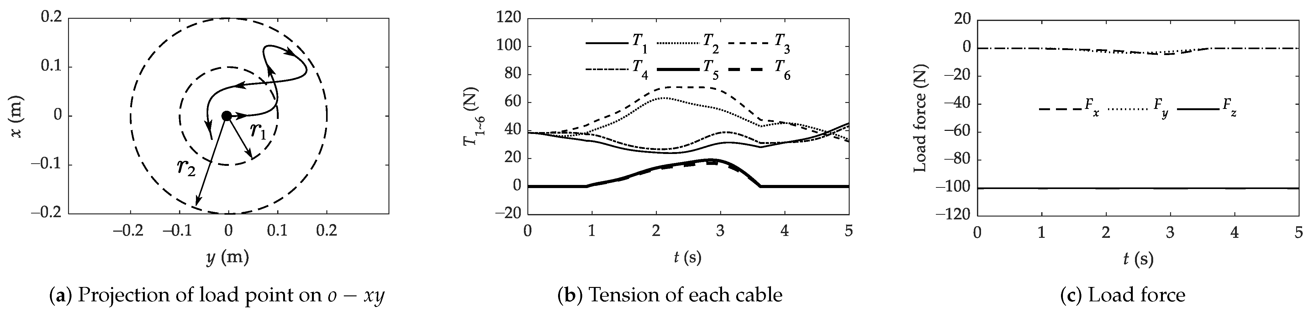
4.1. Simulation of Running Exercise

The simulation model of running exercise with CAPE is established as shown in Figure 10 by utilizing Matlab/Simscape. During the CAPE assisted running exercise, the load point P can be treated as the intersection of the six cables; thus, the astronaut could be simplified as a particle at P. The particle has six degrees of freedom, namely the translation of the x, y, and z-axes and the rotation about each axis. CAPE provides the required load force at the center of the particle.
The forces provided by the astronaut at the particle are demonstrated in Equation (22): in order to verify the effectiveness of the safety protection strategy, horizontal forces were added during the particular time duration in the x-direction F a x and y-direction F a y to drag the particle out of the ideal workspace; F a z is the cosine function about time t. The CAPE exerted the load force in the z-direction F z = 100 N at the particle and provided safe protection. The simulation time was 5 s, the initial position of the load point was ( 0 , 0 , 0.7 ) , and the gravitational acceleration in the environment was 0 m / s 2 . The two-level controller in Section 3 was also established in the simulation model. The final simulation results are shown in Figure 11:
If t [ 0 , 0.3 ] , F a x = 20 N ; Other , F a x = 0 N If t [ 0.5 , 1 ] , F a y = 20 N ; Other , F a y = 0 N F a z = 100 + 20 cos ( 2 π t ) N
The track of the load point in o- x y plane is shown in Figure 11a. In the beginning ( 0 2 s ), the load point P worked in the ideal workspace, while it was deviating to the safe workspace which was affected by the horizontal forces that the astronaut applied. When the load point P entered the safe workspace ( 2 s ), the safety protection strategy was active, and horizontal forces were provided to pull the load point P back to the ideal workspace.
The tension curves of each cable changed over time are shown in Figure 11b. The maximum tension of the load cable was T 3 = 71.0672 N ; the minimum tension of the load cable was T 1 = 23.9249 N . At the beginning, the load point started moving to the safe workspace but was still in the ideal workspace, the safety cable tensions were both 0 N . When the load point moved to the safe workspace, the protection cables shifted to active mode to pull the load point back. Thus, the maximum tension of the protection cable was T 5 = 19.0051 N .
The force curves along with the time change in x-, y-, and z-directions provided by the CAPE for astronauts are shown in Figure 11c, F z was kept at a constant value 100 N . In the beginning, the F x and F y were zero since the load point was in the ideal workspace. When the load point deviated from the ideal workspace, the protection cables started to work, with the combination of load cables to generate horizontal force to pull the load point back. The maximum value of F x was 4.2116 N and the maximum value of F y was 3.2578 N .

4.2. Running Experiment

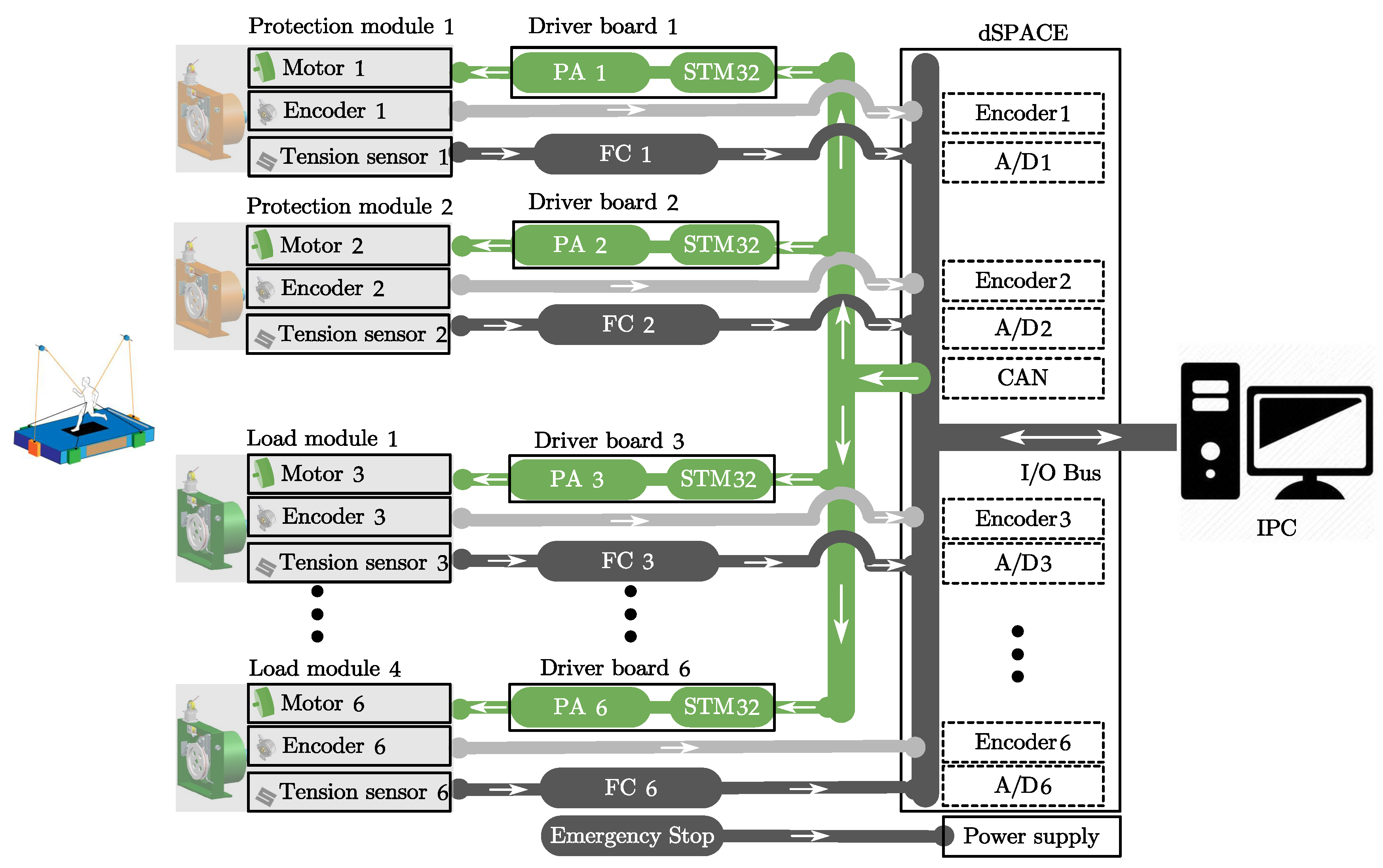
4.2.1. Implementation of the CAPE

Figure 12 shows the prototype of CAPE, including the isometric view, front view, and vertical view. The CAPE consists of four load cable modules, two protection cable modules, driver board, filter circuit, and frame.
The dSPACE hardware-in-loop simulation platform was employed to carry out the running experiment. The overall control plan of CAPE is presented in Figure 13, the flow of CAPE that provided astronaut on-orbit physical exercises can be described as: the host computer (IPC) sends instructions to the slave computer (STM32) through the dSPACE CAN interface; then, the driver board will convert the PWM signal to DC voltage by the power amplifier (PA) circuit to provide power for the torque motor; the cable length and speed will be recorded and transmitted to the host computer in real-time by the encoder through the dSPACE interface; at the same time, the cable tension signal will be processed by the filter circuit (FC) and transmitted to the host computer in real time through the dSPACE A/D interface; next, by the analysis of the aforementioned real-time information, the exercise status of the astronaut could be monitored and an appropriate next step decision could be made by the host computer.

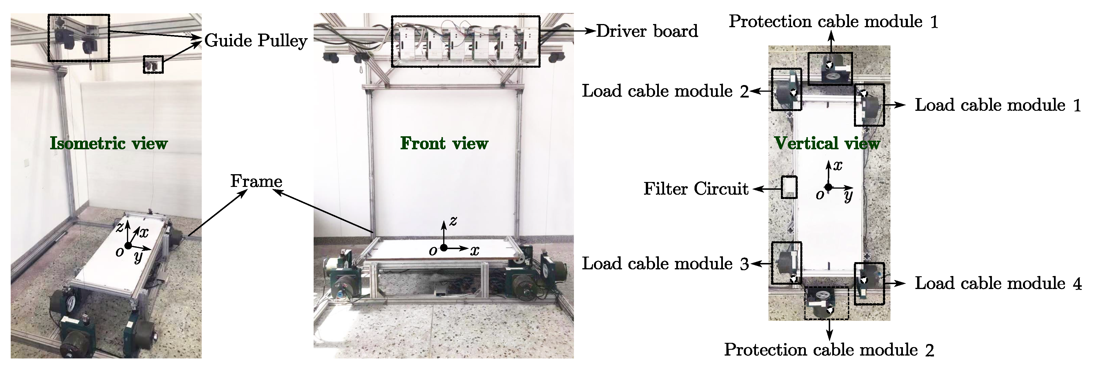
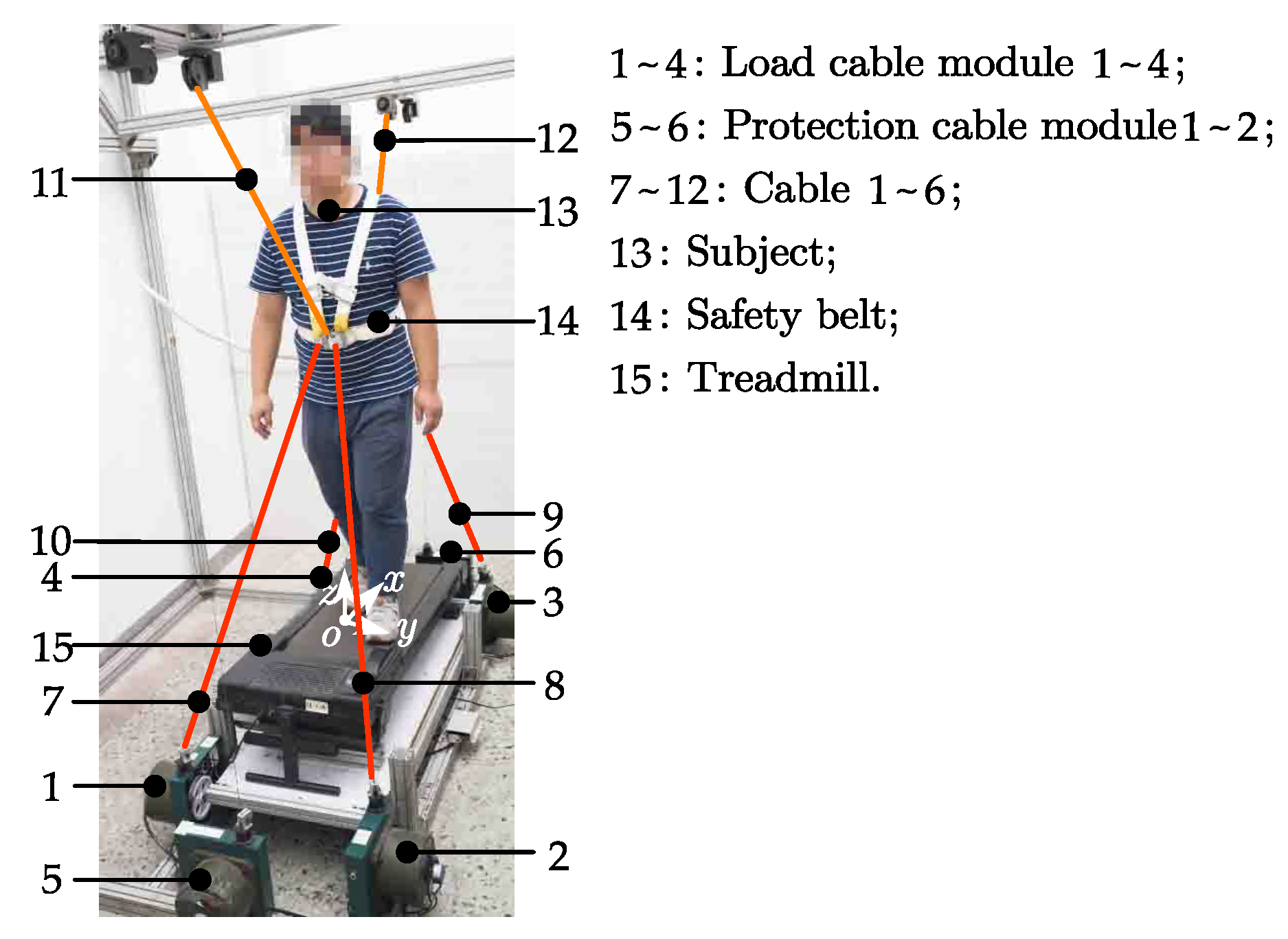
4.2.2. Experiment Platform

The CAPE will eventually be used for the astronaut to carry out exercises in spacecraft; therefore the best experimental environment should be under microgravity. However, the common ways to build a microgravity environment on earth are technically difficult, costly, and usually temporary, like zero-g tower and weightless flight. The main function of the CAPE is to apply the motor-generated load force on the astronaut’s body, the mass of the cable is small, which could be neglected. In other words, the change of gravity will have little impact on the performance of the CAPE. Thus, the running experiment could be conducted on earth with a gravity of 9.8 m / s 2 to verify the effectiveness of the CAPE.
The running exercise experiment is shown in Figure 14. A safety belt with a rope connected to the frame was used to ensure the safety of the subject, and each end of the cables was also fixed on the safety belt. The minimum tension was set to 15 N in cables 5 and 6 to keep them following the movement of the subject in a tight state. The expected load is shown in Equation (23). The subject was asked to run on the treadmill with a load force of 150 N at speed of 1.5 m/s.
F x = 0 N F y = 0 N F z = 150 N

4.2.3. Data Processing
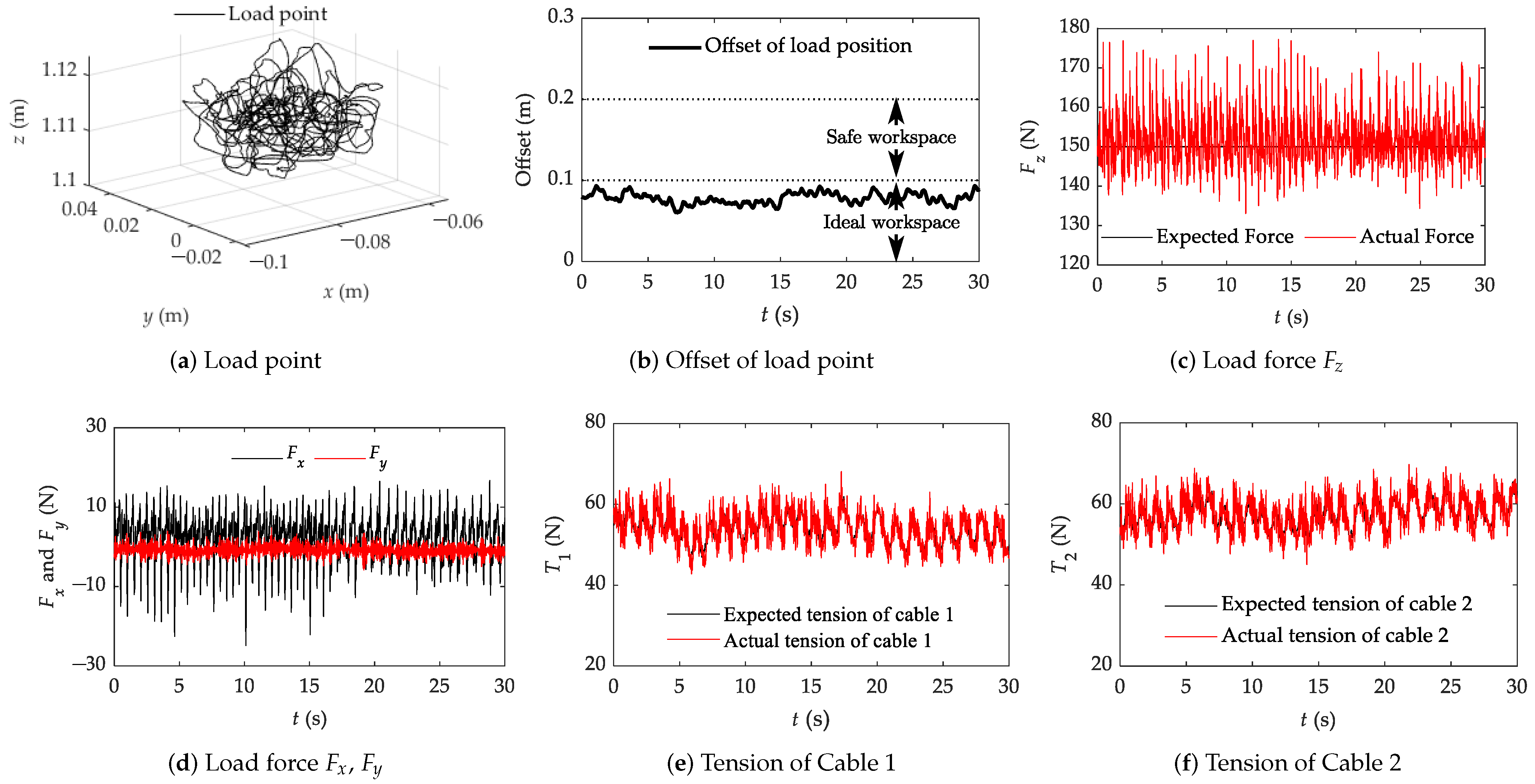
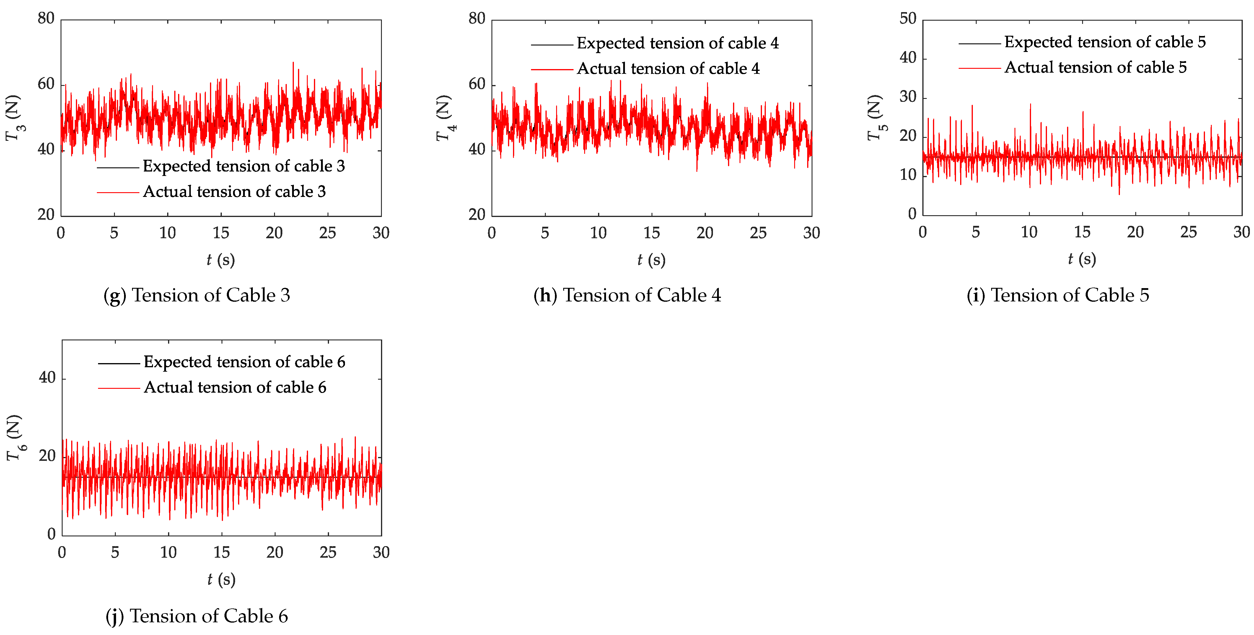
The root mean square error is also adopted to indicate the accuracy of the system, as described in Equation (24). T i a j is the jth actual tension value of cable i in time series and T i e j is the jth expected tension value of cable i in time series. n is the number of the T i a . The load accuracy is calculated to evaluate the tension tracking performance of each cable modular, as presented in Equation (25):
RMSE = j = 1 n ( T i a j T i e j ) 2 n
Load accuracy = ( 1 RMSE max T i e ) × 100 %

4.2.4. Results

The final experiment results are shown in Figure 15. Figure 15a shows the track of the load point P in 3D, and Figure 15b illustrates that the load point P stayed in the ideal workspace during the entire running experiment. The expected and actual load forces in the z-direction are presented in Figure 15c. The actual F z essentially agrees with the expected load force. The actual load force in z fluctuated around 150 N . It should be noted that the error consists of two parts, the system load error and the impact of vibration caused by the running movement of the subject. The root mean square error of actual F z is 6.5770 N and the load accuracy is 95.62%. This demonstrates that the CAPE can provide a load for running.
The horizontal forces are shown in Figure 15d, F x and F y fluctuated around 3 N and 0 N , respectively. The RMSEs of F x and F y are 5.9479 N and 1.5043 N . This indicates that the horizontal forces are small, which have less impact on running exercise.
The tensions curves of cable 1∼6 are shown in Figure 15e–j. As the load point remained in an ideal workspace, the expected tensions of cables 5 and 6 were 15 N during the entire experiment. The RMSEs of each cable tension are 2.5530 N , 2.6252 N , 3.3040 N , 2.9455 N , 2.6220 N , and 3.7572 N . The load accuracies of each cable modular are 95.88%, 95.98%, 94.29%, 94.51%, 82.52%, and 74.95%. In our other study, the load accuracy of cable modular with PID controller only achieves 37.14%, which can not be used in a practical situation. The results also show that the accuracy of cable tensions 5 and 6 are much lower compared to other load cable modules, which is caused by the stiffness of the cable and will lead to the main part of the error when the cable tension is small. Meanwhile, the bigger the cable tension, the smaller the proportion of this part in error, thus the load accuracy will rise.

5. Conclusions

In this paper, a cable-driven astronaut on-orbit physical exercise equipment (CAPE) is described aiming to assist astronauts carrying out multiple physical exercises during space trips as a countermeasure to the negative effect of microgravity: the structure of the cable module based on modular design and the configuration of the CAPE are proposed; Two-level controllers are presented on the basis of the mathematical model of the cable module, including the cable tension distribution algorithm and tension controller; then, the safety protection strategy is also designed; the simulation and experiment of the CAPE-assisted running exercise were carried out. There are several benefits of the CAPE compared with existing devices: multiple exercise modes; easy to set up; take up less space when inactive; easy to replace, maintenance and repair; and the function of safety protection. Both the simulation and experiment results demonstrate: the configuration of the CAPE is reasonable; the tension distribution algorithm of running exercise is accurate, and smooth tension distribution can be achieved; it should be noted that the tension accuracy of the cable module with the controller proposed in Section 3.1.2 is much higher than the precision of PID controller; the safety protection strategy can effectively monitor the astronaut’s exercise status and assist the astronaut back to the ideal workspace to keep safe. In conclusion, the CAPE is economical and space-saving equipment that could assist astronauts to carry out multiple exercises in a microgravity environment with high-precision load force and safety protection. This will greatly help astronauts counteract or mitigate the adverse effects brought by the microgravity environment, maintain the health of bones, muscles, motor coordination, and heart function, and successfully complete space exploration related tasks.
Our future work will concentrate on improving the control strategy to further increase the accuracy of the load force and reduce the horizontal force. The cable tension distribution algorithm of other physical exercises will be conducted and other forms of CAPE assisted physical exercises experiments will also be carried out. We are also developing a new prototype to decrease the weight and volume of the CAPE, which will make the uploading and installation easier.

Author Contributions

Conceptualization, L.L., L.Z. and Y.Z.; Data curation, L.L.; Methodology, L.L. and Y.Z.; Software, L.L.; Supervision, L.Z. and B.W.; Validation, L.L., F.X. and D.S.; Visualization, L.L.; Writing—original draft, L.L.; Writing—review and editing, L.L. and L.Z. All authors have read and agreed to the published version of the manuscript.

Funding

This research was funded by the National Natural Science Foundation of China, Grant No. 6177307.

Institutional Review Board Statement

Not applicable.

Informed Consent Statement

The informed consent has been obtained from the patient(s) to publish this paper.

Data Availability Statement

Not applicable.

Conflicts of Interest

The authors declare no conflict of interest.

References

  1. Komorowski, M.; Fleming, S.; Mawkin, M.; Hinkelbein, J. Anaesthesia in austere environments: Literature review and considerations for future space exploration missions. NPJ Microgravity 2018, 4, 5. [Google Scholar] [CrossRef] [PubMed]
  2. Yang, L.; Du, Z.; Cheng, C.; Shen, P. Building a compound and collaborative governance framework to improve international space sustainability. Glob. Public Policy Gov. 2021, 1, 202–224. [Google Scholar] [CrossRef]
  3. Das, M.C. Space Exploration: It’s Impact on Society—A Critical Review. Int. J. Adv. Technol. Eng. Res. 2018, 1, 92–97. [Google Scholar]
  4. Maffiuletti, N.A.; Green, D.A.; Vaz, M.A.; Dirks, M.L. Neuromuscular electrical stimulation as a potential countermeasure for skeletal muscle atrophy and weakness during human spaceflight. Front. Physiol. 2019, 10, 1030. [Google Scholar] [CrossRef] [Green Version]
  5. Löbrich, M.; Jeggo, P.A. Hazards of human spaceflight. Science 2019, 364, 127–128. [Google Scholar] [CrossRef]
  6. Kandarpa, K.; Schneider, V.; Ganapathy, K. Human health during space travel: An overview. Neurol. India 2019, 67, 176. [Google Scholar]
  7. Hodkinson, P.; Anderton, R.; Posselt, B.; Fong, K. An overview of space medicine. BJA Br. J. Anaesth. 2017, 119, i143–i153. [Google Scholar] [CrossRef] [Green Version]
  8. Seidler, R.D.; Koppelmans, V.; Bloomberg, J.; Mulavara, A.P. 10 Sensory and Sensorimotor Changes with Spaceflight. In Intracranial Pressure in Addition, Its Effect on Vision in Space and on Earth: Vision Impairment in Space; World Scientific: Singapore, 2017; p. 225. [Google Scholar]
  9. Gunga, H.C.; Ahlefeld, V.W.v.; Appell Coriolano, H.J.; Werner, A.; Hoffmann, U. Red blood cells in space. In Cardiovascular System, Red Blood Cells, and Oxygen Transport in Microgravity; Springer: Berlin, Germany, 2016; pp. 35–55. [Google Scholar]
  10. De Santo, N.G.; Cirillo, M.; Kirsch, K.A.; Correale, G.; Drummer, C.; Frassl, W.; Perna, A.F.; Di Stazio, E.; Bellini, L.; Gunga, H.C. Anemia and erythropoietin in space flights. Semin. Nephrol. 2005, 25, 379–387. [Google Scholar] [CrossRef]
  11. Myers, J.; Eke, C.; Werner, C.; Nelson, E.; Mulugeta, L.; Feola, A.; Raykin, J.; Samuels, B.; Ethier, C. Microgravity-Induced Physiological Fluid Redistribution: Computational Analysis to Assess Influence of Physiological Parameters. In Proceedings of the 2016 NASA Human Research Program Investigators’ Workshop (HRP IWS 2016), Galveston, TX, USA, 8–10 February 2016. number GRC-E-DAA-TN29818. [Google Scholar]
  12. Shen, M.; Frishman, W.H. Effects of spaceflight on cardiovascular physiology and health. Cardiol. Rev. 2019, 27, 122–126. [Google Scholar] [CrossRef]
  13. Demontis, G.C.; Germani, M.M.; Caiani, E.G.; Barravecchia, I.; Passino, C.; Angeloni, D. Human pathophysiological adaptations to the space environment. Front. Physiol. 2017, 8, 547. [Google Scholar] [CrossRef]
  14. LeBlanc, A.; Lin, C.; Shackelford, L.; Sinitsyn, V.; Evans, H.; Belichenko, O.; Schenkman, B.; Kozlovskaya, I.; Oganov, V.; Bakulin, A.; et al. Muscle volume, MRI relaxation times (T2), and body composition after spaceflight. J. Appl. Physiol. 2000, 89, 2158–2164. [Google Scholar] [CrossRef]
  15. Crucian, B.E.; Choukèr, A.; Simpson, R.J.; Mehta, S.; Marshall, G.; Smith, S.M.; Zwart, S.R.; Heer, M.; Ponomarev, S.; Whitmire, A.; et al. Immune system dysregulation during spaceflight: Potential countermeasures for deep space exploration missions. Front. Immunol. 2018, 9, 1437. [Google Scholar] [CrossRef] [PubMed]
  16. Van Ombergen, A.; Demertzi, A.; Tomilovskaya, E.; Jeurissen, B.; Sijbers, J.; Kozlovskaya, I.B.; Parizel, P.M.; Van de Heyning, P.H.; Sunaert, S.; Laureys, S.; et al. The effect of spaceflight and microgravity on the human brain. J. Neurol. 2017, 264, 18–22. [Google Scholar] [CrossRef] [PubMed] [Green Version]
  17. Hurst, C.; Scott, J.P.; Weston, K.L.; Weston, M. High-intensity interval training: A potential exercise countermeasure during human spaceflight. Front. Physiol. 2019, 10, 581. [Google Scholar] [CrossRef] [PubMed]
  18. Taddeo, T.A.; Gilmore, S.; Armstrong, C.W. Spaceflight medical systems. In Principles of Clinical Medicine for Space Flight; Springer: Berlin, Germany, 2019; pp. 201–231. [Google Scholar]
  19. Laws, J.; Caplan, N.; Bruce, C.; McGrogan, C.; Lindsay, K.; Wild, B.; Debuse, D.; Wotring, V.; Winnard, A. Systematic review of the technical and physiological constraints of the Orion Multi-Purpose Crew Vehicle that affect the capability of astronauts to exercise effectively during spaceflight. Acta Astronaut. 2020, 170, 665–677. [Google Scholar] [CrossRef]
  20. Smith, S.M.; Heer, M.A.; Shackelford, L.C.; Sibonga, J.D.; Ploutz-Snyder, L.; Zwart, S.R. Benefits for bone from resistance exercise and nutrition in long-duration spaceflight: Evidence from biochemistry and densitometry. J. Bone Miner. Res. 2012, 27, 1896–1906. [Google Scholar] [CrossRef] [PubMed]
  21. Loehr, J.A.; Lee, S.; English, K.L.; Sibonga, J.; Smith, S.M.; Spiering, B.A.; Hagan, R.D. Musculoskeletal adaptations to training with the advanced resistive exercise device. Med. Sci. Sports Exerc. 2011, 43, 146–156. [Google Scholar] [CrossRef]
  22. Scott, J.P.; Weber, T.; Green, D.A. Introduction to the Frontiers research topic: Optimization of exercise countermeasures for human space flight–lessons from terrestrial physiology and operational considerations. Front. Physiol. 2019, 10, 173. [Google Scholar] [CrossRef] [Green Version]
  23. Shuai, L.; Yang, C.Q.; Yang, M.K. Analysis of the Designing Flaws of the Running Machine Facilitated on Tiangong-2. Mech. Manag. Dev. 2018, 33, 4. [Google Scholar]
  24. English, K.L.; Newby, N.J.; Hackney, K.J.; Witt, J.K.D.; Beck, C.E.; Rovekamp, R.N.; Rea, R.L.; Ploutz-Snyder, L.L.; English, K.L.; Newby, N.J. Comparison of Knee and Ankle Dynamometry between NASA’s X1 Exoskeleton and Biodex System 4: 1545 Board #285 May 29, 8. Med. Sci. Sports Exerc. 2014, 46, 419. [Google Scholar]
  25. Rea, R.; Beck, C.; Rovekamp, R.; Neuhaus, P.; Diftler, M. X1: A Robotic Exoskeleton for In-Space Countermeasures and Dynamometry. In Proceedings of the Aiaa Space Conference & Exposition, San Diego, CA, USA, 10–12 September 2013. [Google Scholar]
  26. Scott, J.P.; Weber, T.; Green, D.A. Optimization of Exercise Countermeasures for Human Space Flight—Lessons From Terrestrial Physiology and Operational Implementation. Front. Physiol. 2020, 10, 1567. [Google Scholar] [CrossRef] [PubMed]
  27. Laws, J.M. To the Moon, Mars and Beyond: Recommending Exercise Countermeasures against Musculoskeletal and Cardiovascular Deconditioning during Microgravity Exposure, for Future Spacecraft Applications. Ph.D. Thesis, Northumbria University, Newcastle upon Tyne, UK, 2021. [Google Scholar]
  28. Hidayah, R.; Bishop, L.; Jin, X.; Chamarthy, S.; Stein, J.; Agrawal, S.K. Gait adaptation using a cable-driven active leg exoskeleton (C-ALEX) with post-stroke participants. IEEE Trans. Neural Syst. Rehabil. Eng. 2020, 28, 1984–1993. [Google Scholar] [CrossRef] [PubMed]
  29. Haufe, F.L.; Duroyon, E.G.; Wolf, P.; Riener, R.; Xiloyannis, M. Outside testing of wearable robots for gait assistance shows a higher metabolic benefit than testing on treadmills. Sci. Rep. 2021, 11, 14833. [Google Scholar] [CrossRef] [PubMed]
  30. Georgarakis, A.M. Stability and Mobility: Textile Assistance for the Shoulder for Everyday Life. Ph.D. Thesis, ETH Zurich, Zurich, Switzerland, 2021. [Google Scholar]
  31. Kang, B.B.; Choi, H.; Lee, H.; Cho, K.J. Exo-glove poly II: A polymer-based soft wearable robot for the hand with a tendon-driven actuation system. Soft Robot. 2019, 6, 214–227. [Google Scholar] [CrossRef]
  32. Kim, J.; Lee, G.; Heimgartner, R.; Arumukhom Revi, D.; Karavas, N.; Nathanson, D.; Galiana, I.; Eckert-Erdheim, A.; Murphy, P.; Perry, D.; et al. Reducing the metabolic rate of walking and running with a versatile, portable exosuit. Science 2019, 365, 668–672. [Google Scholar] [CrossRef]
Figure 1. Cable module. (a) schematic diagram of cable module; (b) 3D drawing of the cable module.
Machines 10 00377 g001
Figure 2. Configuration of CAPE.
Machines 10 00377 g002
Figure 3. Exercise modes assisted by CAPE. (a) bench press; (b) deep squat; (c) deadlift; (d) heel raise.
Machines 10 00377 g003
Figure 4. Force analysis diagram of running exercise.
Machines 10 00377 g004
Figure 5. Mechanism diagram of cable module.
Machines 10 00377 g005
Figure 6. Tension controller of the cable module.
Machines 10 00377 g006
Figure 7. (a) ideal track of load position in running exercise; (b) projection of load position on the base of CAPE; (c) countermeasure strategy for load position offset.
Machines 10 00377 g007
Figure 8. Safety protection strategy block diagram of CAPE.
Machines 10 00377 g008
Figure 9. The passive and active switchover of CAPE.
Machines 10 00377 g009
Figure 10. Simulation model.
Machines 10 00377 g010
Figure 11. Simulation results. (a) projection of load point on the o- x y plane; (b) tension of each cable; (c) load force.
Machines 10 00377 g011
Figure 12. Prototype of CAPE.
Machines 10 00377 g012
Figure 13. Overall control plan of CAPE.
Machines 10 00377 g013
Figure 14. Running experiment.
Machines 10 00377 g014
Figure 15. Running experiment results. (a) Track of load point; (b) Offset of load point; (c) Load force F z ; (d) Load force in x and y directions; (e) Tension of Cable 1; (f) Tension of Cable 2; (g) Tension of Cable 3; (h) Tension of Cable 4; (i) Tension of Cable 5; (j) Tension of Cable 6.
Machines 10 00377 g015aMachines 10 00377 g015b
Publisher’s Note: MDPI stays neutral with regard to jurisdictional claims in published maps and institutional affiliations.

