Review

Review on Motion and Load-Bearing Characteristics of the Planetary Roller Screw Mechanism

Shaanxi Engineering Laboratory for Transmissions and Controls, Northwestern Polytechnical University, Xi’an 710072, China
*
Author to whom correspondence should be addressed.
Machines 2022, 10(5), 317; https://doi.org/10.3390/machines10050317
Submission received: 29 March 2022 / Revised: 24 April 2022 / Accepted: 26 April 2022 / Published: 28 April 2022
(This article belongs to the Section Machine Design and Theory)

Abstract

:
Studying the motion and load-bearing characteristics of the planetary roller screw mechanism is the basis for the structural design and performance optimisation of the mechanism. The mechanical structures and working principles of different kinds of planetary roller screw mechanisms are summarised. Published papers on kinematic, load-bearing and dynamic models of the planetary roller screw mechanism are reviewed. Based on the slip state in point contacts at the screw–roller and the nut–roller interfaces, the kinematic models are divided into three types. The finite element method and numerical theory are the two main methods used to develop the load-bearing models. Current dynamic models differ mainly concerning whether they take the rotation of the screw into consideration. In this work, each kind of model is presented in detail along with relevant literature. The main conclusions for each type of model are discussed, and an overview of the future evolution of motion and load-bearing characteristics of the planetary roller screw mechanism are given.

1. Introduction

The planetary roller screw mechanism (PRSM) is a mechanical device used to convert rotational motion into linear motion or vice versa. The most important feature of the PRSM is the use of rollers as the load-bearing and motion transmission elements between the screw and nut. This enables the PRSM to provide more load-bearing points than the ball screw mechanism (BSM) and makes it easy to obtain a larger curvature radius at the contact point. Due to its high power-to-density ratio, high precision and long lifetime, PRSM is more suitable for small pitch transmission. Moreover, the PRSM is an important component of the modern electromechanical servo actuator (EMA).
Compared with the pneumatic and hydraulic servo actuators, the EMA has the advantages of lightweight, high efficiency, convenient installation and maintenance, low operation cost, and no gas or liquid leakage [1]. Thus, the PRSM is widely used in aviation [2,3], aerospace [4,5], ships, vehicles [6], and medical and other fields. For example, the EMA in the thrust vector control system of the European ‘Vega’ launch vehicle used PRSM as its actuator, which successfully passed the tests of vibration, temperature, humidity, durability and vacuum [7]. In 1992, the PRSM was applied to Rolls-Royce aircraft engines and achieved an average trouble-free time of 8711 h [8]. The PRSM installed on the international space station was subjected to a lifetime test in the ESTL laboratory in Britain, which showed that all the samples met the requirements of five years of on-orbit fault-free work [9]. Research by the INSA/Toulouse laboratory in France showed that if the BSM in the EMA of the spoiler plate in a Boeing 787 was replaced by the PRSM, the total weight of the EMA would be reduced by 33% [10]. In addition, the PRSM has the advantages of easy installation, strong rigidity and good dynamic performance [11]. As a result, the PRSM has been applied to a variety of military and civilian products and equipment such as welding robots, electric-pneumatic hybrid actuators [12], machine tools [13], vehicles, ships, marine equipment, aircraft [14,15] and medical equipment [16,17].
Earlier work on the PRSM has included research on meshing characteristics [18,19,20], load distribution [21,22], kinematic analysis [23], lubrication and wear [24,25], manufacturing [26] and thermal modelling [27]. Studying the motion and load-bearing characteristics of the PRSM is the basis for the structural design and performance optimisation of the mechanism. Establishing a complete model considering kinematic, load-bearing and dynamic characteristics is essential for exploring the influence of structural parameters, errors and operating conditions on the meshing, movement, force and deformation of the parts of the mechanism. The abovementioned work is the basis for the drive, control and motor design of the PRSM-based EMA. Developing high-performance PRSMs and promoting their applications is important both theoretically and for practical engineering applications.
Therefore, it is useful to summarise the mechanical structures and working principles of the planetary roller screw mechanism and study its motion and load-bearing characteristics. The rest of this paper is organised as follows: Section 2 introduces the mechanical structures and working principles of the PRSM. Section 3 summarises and analyses the published kinematic, load-bearing and dynamic models. Section 4 suggests an outline of the future evolution of motion and load-bearing characteristics of the PRSM.

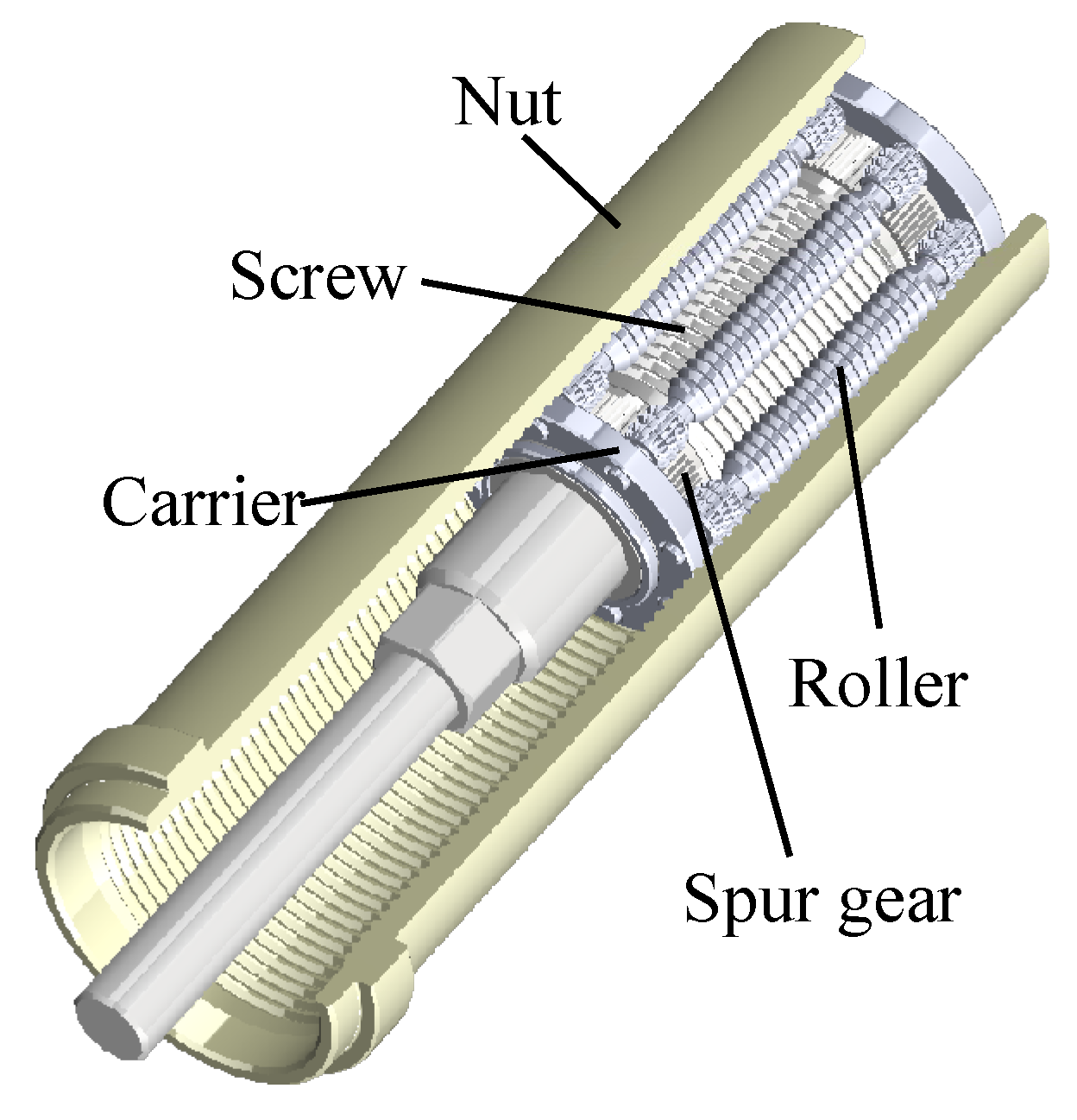
2. Mechanical Structure

The planetary roller screw mechanisms involved in this paper are mainly divided into three types: the standard planetary roller screw mechanism, the inverted planetary roller screw mechanism and the multi-stage planetary roller screw mechanism. This division is based on differences in mechanical structure and motion pattern between the contacting components.

2.1. Standard Planetary Roller Screw Mechanism (Standard PRSM)

The standard planetary roller screw mechanism (the standard PRSM) mainly consists of the screw, nut, rollers, ring gears, and carriers, as shown in Figure 1. The screw and nut have multi-start threads with triangular profiles. The roller has a single-start thread with a rounded profile. Multiple rollers are assembled in a planetary arrangement between the screw and nut with two ring gears fixed at both ends of the nut. The spur gear is machined at both ends of the roller in order to eliminate the inclined torque on the roller caused by the helix angle of the screw. To ensure that the roller rolls normally, the spur gear engages with the internal ring gear installed in the nut so that the axis of the roller will be parallel to the axis of the screw. When the screw rotates, the rollers roll inside the nut. The nut will move forward one lead of the screw for each rotation of the screw.

2.2. Inverted Planetary Roller Screw Mechanism (Inverted PRSM)

The working principle of the inverted planetary roller screw mechanism (the inverted PRSM) is the same as that of the standard PRSM, as shown in Figure 2. Different from the standard PRSM, the inverted PRSM uses the nut as the driving part and the screw as the output part. When the nut rotates, the rollers roll inside of the nut, and the screw will move forward one lead of the nut once the nut turns around. There is no relative axial displacement between the roller and screw, so the length of the roller thread and the screw thread is the same. The external spur gear is machined at both ends of the screw thread. The external meshing of the spur gear of the screw and roller is similar to the internal meshing of the spur gear of the roller and ring gear in the standard PRSM.

2.3. Multi-Stage Planetary Roller Screw Mechanism (Multi-Stage PRSM)

The multi-stage planetary roller screw mechanism (the multi-stage PRSM) is a mechanical device that consists of several single-stage PRSMs for converting rotational motion into long-stroke linear motion. The structure of a two-stage PRSM is shown in Figure 3. As Figure 3 shows, there are two PRSMs. Each one mainly consists of a screw, a nut, rollers, carriers and ring gears, where #1 and #2 denote the corresponding parts belonging to the first and second stages. The screw and nut have multi-start threads with straight flanks. The rollers have a single-start thread with a rounded profile. Multiple rollers are equally spaced between the screw and nut through the carriers, and two ring gears are fixed at both ends of the nut to ensure that the roller axes are parallel to the screw axis and roll normally. In each stage, the nut and screw are connected by two thrust bearings to transmit tensile/compression loads and reduce friction loss. All stage screws except the first are hollow inside. Splined shafts are used to connect all stages of the PRSM so that the external spline and the internal spline of the screw can cooperate together to transmit torque.
The rotation of each stage of the nut and the degree of freedom of movement of the first stage screw are usually restricted in engineering applications. When the first stage screw rotates, the screws in the other stages will rotate and drive the corresponding nut to move axially. Simultaneously, all stage screws except the first will also move axially under the drive of the nut of the upper stage. The mechanism has the advantage of giving an increased linear stroke for nearly the same closed length as a standard PRSM. As the axial motion of the nut can be transferred to the screw in the multi-stage PRSM, its output speed is much higher than the standard PRSM.

3. Published Models

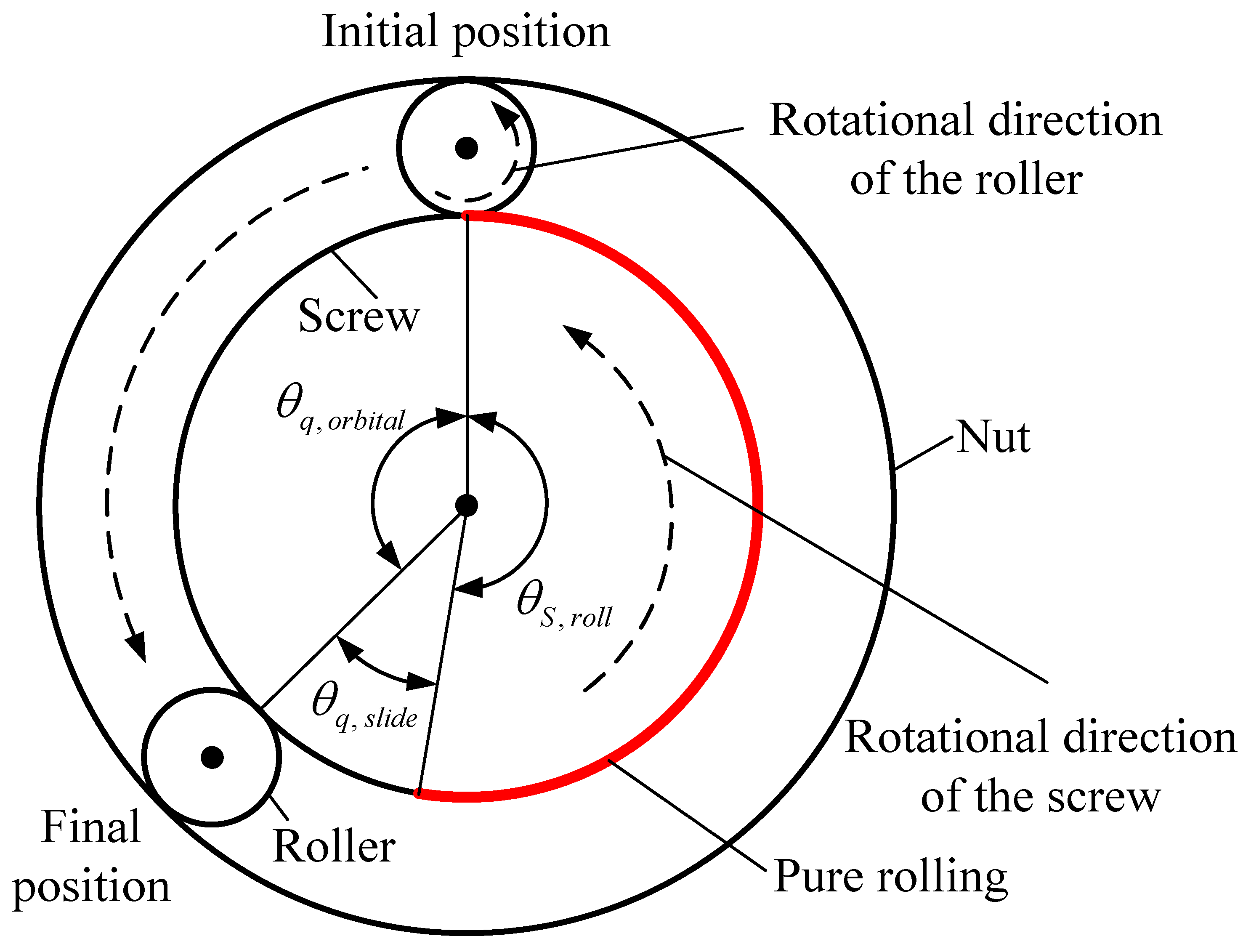
3.1. Kinematic Models

The planetary roller screw mechanism (PRSM) has the characteristics of multi-interface and multi-point contact between the screw and roller and between the nut and roller during the transmission process. When assembly and manufacturing errors are taken into account, the meshing and motion states of the screw, roller and nut will show complex changes. Developing kinematic models considering errors and investigating the influence of errors on the meshing and motion states of the PRSM is significant both for improving the performance and for designing the dimensional tolerance of this mechanism.
Published kinematic models can be mainly divided into three types: pure rolling models with no slip, models including slip between the screw and roller, and models including slip between the nut and roller. The pure rolling model is based on the hypothesis that the screw–roller and the nut–roller are all in pure rolling condition, which means there is no slip between the screw and roller or between the nut and roller. This model can be applied to working principle and motion state analyses of the PRSM. Based on the pure rolling model, Jin et al. [28], Chen et al. [29] and Dang et al. [30] deduced the matching relationship among different structure parameters, which are pitch diameter, thread pitch, rotation direction and number of starts of the screw, roller and nut in the PRSM. Hojjat et al. [31] indicated that there was a slip tendency between the screw and roller during the meshing transmission.
As shown in Figure 4a, Hojjat et al. [31] analysed the forces by comparing the roller–screw with a box on a conveyor and then proposed the slide threshold between the screw and roller. Based on this, they derived an equation for the axial movement of the roller, Δ x R .
Δ x R = P ( n S + d S d R n R )
where Δ x R is the axial movement of the roller per one rotation of the screw. P is the pitch of threads. d S and d R denote diameters of the screw and roller. n S and n R are the number of starts of the threads on the screw and roller. The slip tendency between the screw and roller is illustrated in Figure 4b. In Figure 4b, n R = + 1 or n R = 1 denotes whether the roller thread is right- or left-handed. Equation (1) was also verified by an experiment. The results showed that the roller–screw can be used for both fine transmission of ‘large pitch and small lead’ and fast transmission of ‘small pitch and large lead’. The friction between the screw and roller can drive the roller to roll around the thread of the screw. However, the fact that the roller and screw cannot have the same axial velocities at the contact point, even if these two elements have the same velocities at the tangent of the index circle, was ignored in this research.
For the model including a slip between the screw and roller, Velinsky et al. [32] found that the slip must occur at the screw–roller interface of the PRSM, which will not affect the displacement of the nut, as shown in Figure 5. In Figure 5, θ S , r o l l is the pure rolling angle of the screw. θ q , o r b i t a l and θ q , s l i d e are the orbital angle and slide angle of the roller, respectively. The sum of those angles is equal to the rotational angle of the screw θ S .
θ S = θ S , r o l l + θ q , o r b i t a l + θ q , s l i d e
According to Equation (2), the equation of the slip velocity at the screw–roller interface is derived in Ref. [32], which includes the revolution of the roller and the axial moment of the nut. In addition, the slip state at the screw–roller interface was analysed considering elastic deformation, based on which the transmission efficiency of the PRSM was calculated. This model revealed that the slip velocity at the screw–roller interface may be uncertain, although the actual contact points of the screw and roller were not taken into consideration. Ma et al. [33] studied the relative slip and axial displacement of the roller and screw in the inverted PRSM. The results showed that: (1) the axial movement of the roller does not affect the lead of the mechanism; (2) the axial slip must exist at the nut–roller interface; and (3) the slip velocity at the screw–roller interface can be reduced effectively by decreasing the deviation of the pitch circle. Ma et al. [34] then examined the lead characteristics of the PRSM under different rotation combinations of the screw and roller, considering the slip of the screw and roller. The results showed that the slip between the screw and roller does not affect the axial velocity of the nut when the screw and roller have the same thread rotation directions. However, when the screw and roller have different thread rotation directions, the PRSM can be used for the fine transmission of ‘large pitch and small lead’.
The abovementioned kinematic analyses of the PRSM all assumed that the nut and roller are in a pure rolling state. Taking the slip between the nut and roller into consideration, Johns et al. [23] developed a kinematic model of the PRSM and analysed the axial migration of the rollers relative to the nut. The results indicated that due to the role of the ring gear, the relative slip state at the screw–nut interface can be obtained by the kinematic model. However, a dynamic model (including the contact, friction, mass and so on) needs to be developed to calculate the relative slip velocity at the roller–screw interface. Liu et al. [35] derived equations for calculating axial movement velocities of the screw and nut in the PRSM according to a principle that states that the normal relative velocity at the contact point of the two rigid bodies is zero. The results showed that the axial movement velocity of the nut is related to the contact points at the screw–roller interface when the helical angles and rotation directions of the screw, roller and nut in the PRSM are the same.
In order to take the actual contacting points at the screw–roller interface into consideration, Fu et al. [36] proposed a kinematic model based on the constraint that the set defined by the roller floating region is not empty. The boundary of the roller floating region and the path of the motion transmission from the screw to the nut were obtained, followed by an analysis of the influence of the run-out errors and position errors on the roller floating region, axial clearance and transmission error, as shown in Figure 6. In Figure 6, e denotes the run-out error and φ is the phase angle of a run-out error. Sandu et al. [37] developed a static model capable of calculating the slip velocity at an arbitrary point on the contacting trajectory.

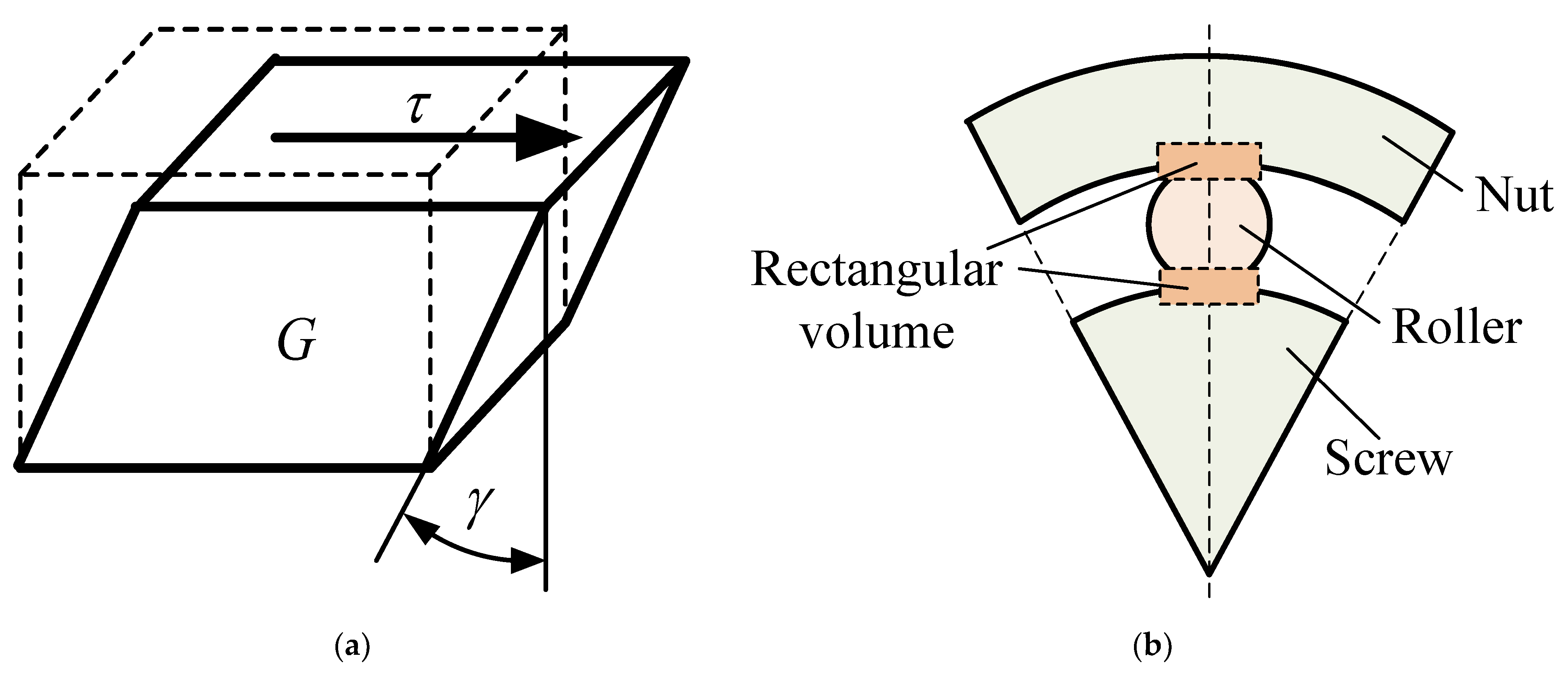
3.2. Load-Bearing Models
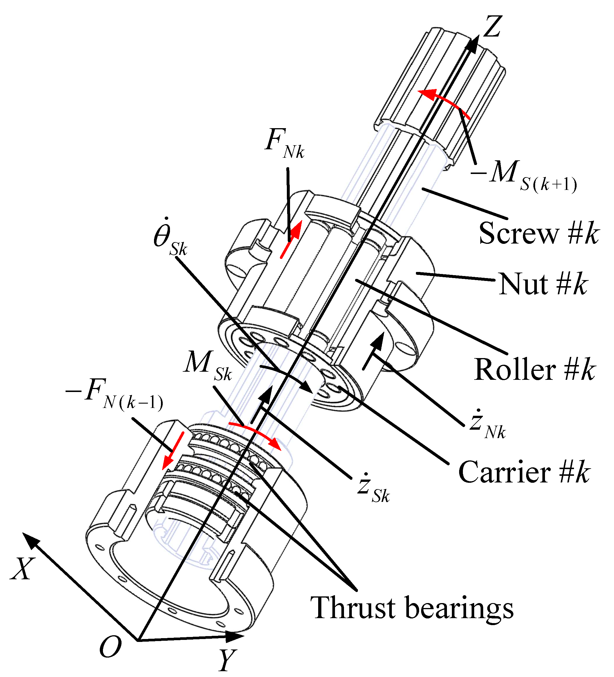
As a rolling screw transmission device, the PRSM has an outstanding advantage of large load-bearing capacity. The transmission accuracy and service life of the PRSM are important performance indicators, but they are affected by load-bearing characteristics, such as thread force, axial stiffness, thread load distribution, and friction and wear. Under high-load conditions, the load-bearing characteristics are directly related to the performance of the PRSM.
The published PRSM load-bearing models are mainly divided into models based on finite element software and models based on numerical theory. For the load-bearing models based on finite element software, Ma et al. [38] studied the influence of the contact angle and helix angle on the axial elastic deformation of the PRSM under different axial loads. The results showed that the Hertzian contact deformation was the main deformation, and the axial deformation decreased with the increase in contact angle and helix angle. In order to take the axial deformation of the rollers into consideration, Ryś et al. [39] developed a PRSM load distribution model by equating the force–deformation relationship between each pair of thread teeth to the shear stress–strain relationship of multiple rectangular elements, as shown in Figure 7. In Figure 7a, τ is the shear stress at the surface of the rectangular volume, and γ is the shear strain. The ratio between the τ and γ is equal to the shear modulus G. According to Equation (3), the stiffness of the rectangular volume is calculated.
τ γ = G
Since both the screw and the nut in PRSM are in point contact state with the roller, a large error will be introduced if the formula in Sun et al. [40] is directly used to calculate the deformation of the screw, roller and nut thread.
Lisowski et al. [41] created a finite element model of the contact of the single pair thread in the PRSM and obtained the stress and thread deformation curve. They also proposed a load model of the PRSM with reference to the direct stiffness method. Lisowski et al. [42] then analysed the load distribution of the PRSM under the influence of random pitch error and calculated the stiffness coefficient of the interactions between the screw–roller and the roller–nut using the finite element method. In addition, Lisowski et al. [43] proposed an optimisation of thread root undercut in the PRSM. Using a three-dimensional finite element (3D FE) method, Abevi et al. [44] proposed a sectorial model of the inverted PRSM involving an entire roller, as shown in Figure 8. The axial stiffness and the load distribution under both compressive and tensile loads were investigated, and complementary experiments were carried out to measure the axial deflection of the screw and rollers. The results showed that the external load was unequally shared over rollers and contacting threads, which was due to manufacturing and positioning errors.
In order to save computing time, Abevi et al. [21] used beam elements, bar elements, non-linear spring elements and rigid-body elements to model the different components of the PRSM and their interactions (Figure 9), assuming that all materials were in the elastic range. The results obtained from this approach were compared to those computed with a three-dimensional finite element model, which suggested that the calculations were very accurate. Taking different assembly methods and force states into consideration, Liu et al. [45] proposed a finite element analysis model of the PRSM and systematically analysed the load distribution under different working temperatures. The results showed that the cumulative deformation of the screw and nut in the axial direction had a significant impact on the load distribution. Zu et al. [46] designed a high-load PRSM under aerospace conditions, followed by a study of the bearing characteristics and the equivalent finite element model of the PRSM.
Based on Hertzian contact theory, Yang et al. [47] proposed a calculation model for the deformation and axial static stiffness of the PRSM and obtained the axial stiffness curve. Using the direct stiffness method, Jones et al. [48] developed a stiffness model of the PRSM. As shown in Figure 10a, this approach modelled the entire mechanism as a large spring system, from which the load distribution across the threads of the individual components can be calculated. In Figure 10a, kS, kq and kN are the stiffness of the springs of the screw, roller and nut, respectively. kSq and kNq are the non-linear stiffness at the screw–roller and nut–roller interfaces. The values of kS, kq and kN are obtained by using Hooke’s law. The non-linear stiffness, kSq or kNq, includes the contact stiffness and thread stiffness in Ref. [48]. This method improves the accuracy of the stiffness model because no simplification is required. However, the thread stiffness is equivalent to the annular plate model with a contact force, as shown in Figure 10b, which cannot reflect the influence of thread parameters on the thread stiffness.
To improve the load distribution of the roller thread, Ma et al. [49] demonstrated a model including errors based on the relationship of deformation compatibility on two contact sides of the roller. The results showed that the smaller the load, the larger the fluctuation of load distribution on the teeth of the roller thread; the negative errors had the advantage of decreasing load ratios of the first three teeth of the roller thread. This research can help to guide the reasonable control of errors in the manufacturing process of the PRSM. Based on this, Ma et al. [50] then proposed a load distribution model of the PRSM, which can comprehensively take the coupling of errors, wear and temperature changes into consideration.
Considering different installation configurations, Zhang et al. [51] offered a model for calculating load distributions of threads in the PRSM. As shown in Figure 11, this method modelled the screw, roller and nut in the PRSM into a combination of coil spring and leaf spring. A matrix equation was developed according to the relationships of deformation compatibility and force equilibrium. The effects of installations, load conditions, structural parameters and thread form parameters on the load distributions of thread were taken into consideration. The results showed that the uneven load distributions on threads were mainly due to the accumulative axial deformations of the screw and nut. To distribute the load uniformly over the threads of the PRSM, Zhang et al. [22] provided an improved approach in which the thread form parameters of the roller and nut were redesigned and the contact conditions of the roller with the screw and nut were changed. Based on this, Zhang et al. [52] proposed a thread load balance design method for the PRSM, including structural parameter design and thread tolerance design.
Based on differential geometry and Hertzian contact theory, Guo et al. [53] created a new type of axial stiffness model with improved accuracy of static and dynamic analysis, followed by an experiment to verify this model. Zhang et al. [54] proposed a model to calculate load distribution over threads of the PRSM with pitch deviation and studied the effects of pitch deviation on load distribution of the PRSM through numerical analyses. The experimental results showed that pitch deviations led to the fluctuation of load distributions over threads. Taking radial load and machining errors into consideration, Du et al. [55] developed mechanical models of the PRSM and calculated contact loads of all threads by applying Hertzian contact theory and thread cumulative deformation. The results showed that the contact forces over threads periodically changed under radial loads and that variation of machining errors dramatically changed load distribution and fatigue life. Yao et al. [56] proposed a static model of the PRSM considering errors. Liu et al. [57] proposed a meshing method of a convex–concave contact planetary roller–screw mechanism and analysed its meshing bearing characteristics.

3.3. Dynamic Models

Velinsky et al. [32] showed that for the standard PRSM, there must be sliding between the screw and roller, and this sliding will not affect the axial displacement of the nut. This means that the rotation and revolution speeds of the rollers in the PRSM cannot be obtained by kinematic analysis alone. Therefore, in order to obtain the force and motion state of the PRSM, it is necessary to carry out dynamic research on the mechanism. Jones et al. [23] pointed out that the rotational speed of the roller and carrier was related to the friction characteristics between the screw and roller in the PRSM. Moreover, the mass of the moving parts, the rotational speed of the driving parts and the external load will affect the dynamic characteristics of the PRSM. To improve the transmission performance of the PRSM, it is important to explore the dynamic characteristics under different structural parameters and working conditions.
The main difference between present dynamic models is whether they take the rotation of the screw into consideration. As regards models that considered the screw rotation, Jones et al. [58] proposed a dynamic model of the PRSM based on the Lagrange equation. The rotation of the screw and the revolution of rollers were chosen as generalised degrees of freedom. The transient and steady-state results of the revolution of rollers under step inputs were calculated. While using the Lagrange equation has the advantage of avoiding force analyses of the screw, roller, nut and carrier, the force state of each component cannot be obtained directly from the dynamic equations. In order to solve this problem, Fu et al. [59] developed a non-linear six degrees of freedom dynamic model, in which the load distribution coefficient was introduced to describe the load distribution among threads of PRSM and studied the transient and steady-state behaviours of the PRSM under a heavy and light external load. Fu et al. [60] then proposed an efficient dynamic model by combining the Lagrange method and Newton’s section law to reduce computation time. Taking elastic deformations into account, Fu et al. [61] proposed a dynamic model of the double-nut planetary roller–screw mechanism. To examine the dynamic characteristics, Ma et al. [62] proposed a finite element model of single-stage PRSM and explored the dynamic characteristics of the PRSM based on the explicit dynamic finite element method. He [63] and Ma et al. [64] proposed a dynamic model of single-stage PRSM based on the bond graph theory, accounting for friction, axial clearance and screw stiffness. Wu et al. [65] developed a purely torsional model of single-stage PRSM based on Hertzian contact theory and examined the relationship between nature frequencies and the number of rollers.
Some dynamic models did not take the screw rotation into consideration. Yue et al. [66] developed a three-dimensional model of single-stage PRSM and investigated the influences of supporting patterns, working positions of nut and centrifugal force on PRSM’s inherent frequencies through finite element simulation. Guo et al. [67] developed a dynamic model of single-stage PRSM considering thread meshing stiffness based on Hertzian contact theory and conducted a PRSM dynamic experiment to verify the model.
The research mentioned above mainly focused on single-stage PRSM. Based on the structural characteristics of the multi-stage PRSM, Li et al. [68] analysed the motion and force in and between the different stages (Figure 12). In Figure 12, FN(k−1) and FNk are the forces acting on the nuts at the (k−1)th and kth stages. MNk and MN(k+1) are the torques acting on the screws at the kth and (k + 1)th stages. The torques of the screw #1 (k = 1) and the force acting on the nut at the last stage are assumed to be given in Ref. [68]. θ ˙ S k and z ˙ S k are the rotational and axial velocities of the screw #k. The axial velocity of the nut #k, z ˙ N k , is given as
z ˙ N k = z ˙ S k + θ ˙ S k L S k 2 π
where LSk is the lead of the screw #k. The rigid-body motion equations of the multi-stage PRSM were derived by using Newton’s second law, and the method for solving the motion equations was given in Ref. [68]. The influence of the friction coefficients in and between the different stages on the dynamic characteristics of the multi-stage PRSM was discussed. In order to reduce the computing time, Li et al. [69] proposed an efficient dynamic model of multi-stage PRSM based on the Lagrange method. The structure and motion analysis of a two-stage PRSM in Ref. [69] were presented as shown in Figure 13. In Figure 13, θ ˙ S 1 , θ ˙ S 2 , θ ˙ P 2 and θ ˙ q 2 are the rotational velocities of the screw #1, screw #2, carrier #2 and roller #2. Because screw #1 and screw #2 are connected by a splined shaft, the rotational velocities of the screws are equal.
θ ˙ S 1 = θ ˙ S 2
Equation (5) is used to calculate the rotational velocity of the screw in each stage of the mechanism in Ref. [69]. The transient and steady-state behaviours of multi-stage PRSM were simulated, and the influence of friction coefficients and thread pitches on motion and forces acting on the multi-stage PRSM was analysed.

4. Conclusions

A review of motion and load-bearing characteristics for the planetary roller screw mechanism has been presented in this paper. The published kinematic models are divided into three types: pure rolling models with no slip, models including slip between the screw and roller, and models including slip between the nut and roller. The published load-bearing models are divided into models based on finite element software and models based on numerical theory. The published dynamic models are divided into two groups according to the motion of the screw. Although previously published papers make a great contribution to the study of the PRSM, the following issues should be considered in further research.
1.
Under the influence of errors, the meshing and motion states of each element of the PRSM need to be calculated, and the dynamic interactions of the meshing, movement and deformation of the elements need to be explored as well. In the multi-stage PRSM, the position and movement of one stage of the screw and nut will affect those of the next stage of the screw and nut, which is likely to cause complex motion coupling under the effect of errors.
2.
The load sharing among rollers should be considered in the load-bearing models. The influence of the bending and torsional stiffness of the screw on the load-bearing characteristics of the PRSM needs to be investigated. For the multi-stage PRSM, the bending and torsion deformation of the screws need to be taken into account in strength check, instability analysis and transmission accuracy calculation due to the uneven load distribution caused by errors.
3.
The influence of manufacturing and assembly errors on the motion, force and deformation of the PRSM needs to be comprehensively analysed. A dynamic analysis of the PRSM considering errors and elastic deformation is very important to reveal the dynamic bearing characteristics of the mechanism and to design a high-speed and high-dynamic PRSM-based EMA.

Author Contributions

X.L. summarised the published models and wrote the paper; G.L. provided guidance and edited the manuscript; X.F. prepared the figures; S.M. edited the manuscript. All authors have read and agreed to the published version of the manuscript.

Funding

This paper is supported by the National Natural Science Foundation of China (Grant No. 51905428, 51875458), the Key Project of the National Natural Science Foundation of China (Grant No. 51535009), (Grant No. 2019YFB2004700), Natural Science Basic Research Plan in Shaanxi Province of China (Grant No. 2020JQ-178).

Institutional Review Board Statement

Not applicable.

Informed Consent Statement

Not applicable.

Data Availability Statement

Not applicable.

Acknowledgments

We would like to thank David Bowen for providing the language help in this paper.

Conflicts of Interest

The authors declare no conflict of interest. The funders had no role in the design of the study; in the collection, analyses, or interpretation of data; in the writing of the manuscript, or in the decision to publish the results.

References

  1. Mare, J.C.; Fu, J. Review on signal-by-wire and power-by-wire actuation for more electric aircraft. Chin. J. Aeronaut. 2017, 30, 857–870. [Google Scholar] [CrossRef]
  2. Gruszecki, J.; Grzybowski, J.; Rzucidło, P. Electro-mechanical actuators for general aviation fly-by-wire aircraft. Aviation 2005, 9, 19–25. [Google Scholar] [CrossRef]
  3. Vander, F.L.; Schlegel, C.; Christmann, M.; Regula, G.; Hill, C.; Giangrande, P.; Maré, J.; Egaña, I. Implementation of a modelica library for simulation of electromechanical actuators for aircraft and helicopters. In Proceedings of the 10th International Modelica Conference, Lund, Sweden, 10 March 2014. [Google Scholar] [CrossRef] [Green Version]
  4. Albright, J.; Moore, D. Development and implementation of electromechanical actuators for the X-38 atmospheric test vehicles. In Proceedings of the AIAA Atmospheric Flight Mechanics Conference and Exhibit, Honolulu, HI, USA, 18–21 March 2008. [Google Scholar] [CrossRef]
  5. Cleayssen, F.; Janker, P.; Leletty, R.; Sosniki, O. New actuators for aircraft, space and military applications. In Proceedings of the 12th International Conference on New Actuator, Bremen, Germany, 14–16 June 2010. [Google Scholar]
  6. Kawamoto, Y.; Suda, Y.; Inoue, H.; Kondo, T. Electro-mechanical suspension system considering energy consumption and vehicle manoeuvre. Veh. Syst. Dyn. 2008, 46, 1053–1063. [Google Scholar] [CrossRef]
  7. Vanthuyne, T. An electrical thrust vector control system for the VEGA launcher. In Proceedings of the 13th European Space Mechanisms and Tribology Symposium, Vienna, Austria, 23–25 September 2009. [Google Scholar]
  8. Lemor, P.C. The roller screw: An efficient and reliable mechanical component of electro-mechanical actuators. In Proceedings of the 31st Intersociety Energy Conversion Engineering Conference, Washington, DC, USA, 11–16 August 1996. [Google Scholar] [CrossRef]
  9. Pochettini, P.; Ballesio, M.; Gallieni, D.; Gill, S. Hexapod/Sage III roller screws lifetime and lubrication tests. Eur. Space Agency-Publ. 1999, 438, 49–56. [Google Scholar]
  10. Budinger, M.; Reysset, A.; Halabi, T.; Vasiliu, C.; Maré, J. Optimal preliminary design of electro -mechanical actuators. Proc. Inst. Mech. Eng. Part G J. Aerosp. Eng. 2014, 228, 1598–1616. [Google Scholar] [CrossRef] [Green Version]
  11. Liu, G.; Ma, S.J.; Tong, R.T.; Guan, D. New development and key technology of planetary roller screw. J. Mech. Transm. 2012, 36, 103–108. [Google Scholar]
  12. Csonka, G.; Waldron, K.J. Characterization of an electric-pneumatic hybrid prismatic actuator. J. Mech. Robot. 2010, 2, 021008. [Google Scholar] [CrossRef]
  13. Munn, P. A roller screw with special qualities. In Proceedings of the 22nd International Machine Tool Design and Research Conference, London, UK, 1 April 1982. [Google Scholar] [CrossRef]
  14. Sokolov, P.A.; Blinov, D.S.; Ryakhovskii, O.A.; Ochkasov, E.E. Promising rotation–translation converters. Russ. Eng. Res. 2008, 28, 949–956. [Google Scholar] [CrossRef]
  15. Arriola, D.; Thielecke, F. Model-based design and experimental verification of a monitoring concept for an active-active electromechanical aileron actuation. Mech. Syst. Signal. Process. 2017, 94, 322–345. [Google Scholar] [CrossRef]
  16. Ohashi, Y.; Andrade, A.D.; Muller, J.; Nose, Y. Control System modification of an electromechanical pulsatile total artifical heart. Artif. Organs 1997, 21, 1308–1311. [Google Scholar] [CrossRef]
  17. Sasaki, Y.; Chikazawa, G.; Nogawa, M.; Nishida, H.; Koyanagi, H.; Takatani, S. Evaluation of a roller screw linear muscle actuator for an implantable ventricular assist device using trained and untrained latissimus dorsi muscles. Artif. Organs 1999, 23, 262–267. [Google Scholar] [CrossRef] [PubMed]
  18. Jones, M.H.; Velinsky, S.A. Contact kinematics in the roller screw mechanism. J. Mech. Des. 2012, 135, 451–459. [Google Scholar] [CrossRef]
  19. Fu, X.J.; Liu, G.; Ma, S.J.; Tong, R.T.; Lim, T.C. A comprehensive contact analysis of planetary roller screw mechanism. J. Mech. Des. 2017, 139, 98. [Google Scholar] [CrossRef]
  20. Sandu, S.; Biboulet, N.; Nelias, D.; Abevi, F. An efficient method for analyzing the roller screw thread geometry. Mech. Mach. Theory 2018, 126, 243–264. [Google Scholar] [CrossRef]
  21. Abevi, F.; Daidie, A.; Chaussumier, M.; Sartor, M. Static load distribution and axial stiffness in a planetary roller screw mechanism. J. Mech. Des. 2016, 138, 012301-1–012301-11. [Google Scholar] [CrossRef]
  22. Zhang, W.J.; Liu, G.; Tong, R.T.; Ma, S.J. Load distribution of planetary roller screw mechanism and its improvement approach. Proc. Inst. Mech. Eng. C J. Mech. Eng. Sci. 2015, 230, 3304–3318. [Google Scholar] [CrossRef]
  23. Jones, M.H.; Velinsky, S.A. Kinematics of roller migration in the planetary roller screw mechanism. J. Mech. Des. 2012, 134, 061006-1–061006-6. [Google Scholar] [CrossRef]
  24. Auregan, G.; Fridrici, V.; Kapsa, P.; Rodrigues, F. Experimental simulation of rolling-sliding contact for application to planetary roller screw mechanism. Wear 2015, 332–333, 1176–1184. [Google Scholar] [CrossRef]
  25. Xie, Z.J.; Xue, Q.H.; Wu, J.Q.; Gu, L.; Wang, L.Q.; Song, B.Y. Mixed-lubrication analysis of planetary roller screw. Tribol. Int. 2019, 140, 105883. [Google Scholar] [CrossRef]
  26. Zhang, D.W.; Zhao, S.D.; Wu, S.B.; Zhang, Q.; Fan, S.Q.; Li, J.X. Phase characteristic between dies before rolling for thread and spline synchronous rolling process. Int. J. Adv. Manuf. Technol. 2015, 81, 513–528. [Google Scholar] [CrossRef]
  27. Qiao, G.; Liu, G.; Ma, S.J.; Wang, Y.W.; Li, P.; Lim, T.C. Thermal characteristics analysis and experimental study of the planetary roller screw mechanism. Appl. Therm. Eng. 2019, 149, 1345–1358. [Google Scholar] [CrossRef]
  28. Jin, Q.Z.; Yang, J.; Sun, J.L. Motion characteristics and parameter selection of the planetary roller screw mechanism. Manuf. Technol. Mach. Tool 1998, 1998, 13–15. [Google Scholar]
  29. Chen, M.L. Transmission performance of the differential screw mechanism. J. Mech. Transm. 2008, 2008, 98–100. [Google Scholar]
  30. Dang, J.L.; Liu, G.; Ma, S.J.; Tong, R.T.; Luo, H. Motion principle and simulation analysis of inverted planetary roller screw mechanism. J. Syst. Simul. 2013, 25, 1646–1651. [Google Scholar]
  31. Hojjat, Y.; Agheli, M. A comprehensive study on capabilities and limitations of roller screw with emphasis on slip tendency. Mech. Mach. Theory. 2009, 44, 1887–1899. [Google Scholar] [CrossRef]
  32. Velinsky, S.A.; Chu, B.; Lasky, T.A. Kinematics and efficiency analysis of the planetary roller screw mechanism. J. Mech. Des. 2009, 131, 011016-1–011016-8. [Google Scholar] [CrossRef]
  33. Ma, S.J.; Liu, G.; Tong, R.T.; Zhang, W.J. Kinematic analysis of an inverted planetary roller screw considering roller pitch circle mismatch. China Mech. Eng. 2014, 25, 1421–1426. [Google Scholar] [CrossRef]
  34. Ma, S.J.; Zhang, T.; Liu, G.; Tong, R.T.; Fu, X.J. Kinematics of planetary roller screw mechanism considering helical directions of screw and roller threads. Math. Probl. Eng. 2015, 2015, 1–11. [Google Scholar] [CrossRef] [Green Version]
  35. Liu, Y.Q.; Wang, J.S.; Cheng, H.X.; Sun, Y.P. Kinematics analysis of the roller screw based on the accuracy of meshing point calculation. Math. Probl. Eng. 2015, 2015, 1–10. [Google Scholar] [CrossRef] [Green Version]
  36. Fu, X.J.; Liu, G.; Ma, S.J.; Tong, R.T.; Lim, T.C. Kinematic model of planetary roller screw mechanism with run-out and position errors. J. Mech. Des. 2018, 140, 032301-1–032301-10. [Google Scholar] [CrossRef]
  37. Sandu, S.; Biboulet, N.; Nelias, D.; Abevi, F. Analytical prediction of the geometry of contact ellipses and kinematics in a roller screw versus experimental results. Mech. Mach. Theory 2019, 131, 115–136. [Google Scholar] [CrossRef]
  38. Ma, S.J.; Liu, G.; Tong, R.T.; Zhang, X.C. Finite element analysis of axial elastic deformation for planetary roller screw. J. Mech. Transm. 2012, 36, 78–81. [Google Scholar]
  39. Ryś, J.; Lisowski, F. The computational model of the load distribution between elements in planetary roller screw. J. Theor. Appl. Mech. 2014, 52, 699–705. [Google Scholar]
  40. Sun, J.L.; Jin, Q.Z. A study of static stiffness of planetary roller screw. J. Hubei Inst. Technol. 1993, 8, 24–29. [Google Scholar]
  41. Lisowski, F. The analysis of displacements and the load distribution between elements in a planetary roller screw. Appl. Mech. Mater. 2014, 680, 326–329. [Google Scholar] [CrossRef]
  42. Lisowski, F. The specific dynamic capacity of a planetary roller screw with random deviations of a thread pitch. J. Theor. Appl. Mech. 2017, 55, 991–1001. [Google Scholar] [CrossRef] [Green Version]
  43. Lisowski, F. Optimization of thread root undercut in the planetary roller screw. Tech. Trans. 2017, 9, 219–227. [Google Scholar] [CrossRef]
  44. Abevi, F.; Daidie, A.; Chaussumier, M.; Orieux, S. Static analysis of an inverted planetary roller screw mechanism. J. Mech. Robot. 2016, 8, 041020-1–041020-14. [Google Scholar] [CrossRef]
  45. Liu, S.M.; Liu, G.; Ma, S.J.; Tong, R.T.; Zhang, W.J. Research of the load distribution of planetary roller screw mechanism under different working temperatures. J. Mech. Transm. 2016, 40, 14–19. [Google Scholar]
  46. Zu, L.; Zhang, Z.; Gao, L. Design and bearing characteristics of planetary roller screws based on aerospace high-load conditions. Adv. Mech. Eng. 2018, 10, 1–11. [Google Scholar] [CrossRef]
  47. Yang, J.J.; Wei, Z.X.; Zhu, J.S.; Du, W. Calculation of load distribution of planetary roller screws and static rigidity. J. Huazhong Univ. of Sci. Tech. 2011, 39, 1–4. [Google Scholar]
  48. Jones, M.H.; Velinsky, S.A. Stiffness of the roller screw mechanism by the direct method. Mech. Based Des. Struct. Mach. 2014, 42, 17–34. [Google Scholar] [CrossRef]
  49. Ma, S.J.; Liu, G.; Fu, X.J.; Zhang, W.J. Load distribution of rollers considering errors in planetary roller screw mechanism. J. Harbin Inst. Technol. 2015, 47, 98–102. [Google Scholar] [CrossRef]
  50. Ma, S.J.; Liu, X.F.; Liu, G.; Peng, C.; Guo, H. Load distribution of planetary roller screw mechanism with error, thread wear and temperature change. J. Northwestern Polytech. Univ. 2017, 35, 655–660. [Google Scholar]
  51. Zhang, W.J.; Liu, G.; Ma, S.J.; Tong, R.T. Load distribution of planetary roller screw mechanism with different installations. J. Northwestern Polytech. Univ. 2015, 33, 229–236. [Google Scholar] [CrossRef]
  52. Zhang, W.J.; Liu, G.; Tong, R.T.; Ma, S.J. Thread load balance design method of planetary roller screw mechanism. J. Northwestern Polytech. Univ. 2016, 34, 499–507. [Google Scholar] [CrossRef]
  53. Guo, J.N.; Peng, H.; Huang, H.Y.; Liu, Z.S. Analytical and experimental of planetary roller screw axial stiffness. In Proceedings of the IEEE International Conference on Mechatronics and Automation (ICMA), Takamatsu, Kagawa, Japan, 6–9 August 2017. [Google Scholar]
  54. Zhang, W.J.; Liu, G.; Ma, S.J.; Tong, R.T. Load distribution over threads of planetary roller screw mechanism with pitch deviation. Proc. Inst. Mech. Eng. C J. Mech. Eng. Sci. 2018, 233, 4653–4666. [Google Scholar] [CrossRef]
  55. Du, X.; Chen, B.K.; Zheng, Z.D. Investigation on mechanical behavior of planetary roller screw mechanism with the effects of external loads and machining errors. Tribol. Int. 2021, 154, 3304–3318. [Google Scholar] [CrossRef]
  56. Yao, Q.; Zhang, M.C.; Liu, Y.S.; Ma, S.J. Multi-objective optimization of planetary roller screw mechanism based on improved mathematical modeling. Tribol. Int. 2021, 161, 98. [Google Scholar] [CrossRef]
  57. Liu, R.R.; Cheng, Y.H.; Du, X.; Cheng, B.K. Meshing and bearing characteristics of convex-concave contact planetary roller screw mechanism. J. Harbin Inst. Technol. 2022, 54, 49–57. [Google Scholar] [CrossRef]
  58. Jones, M.H.; Velinsky, S.A.; Lasky, T.A. Dynamics of the planetary roller screw mechanism. J. Mech. Robot. 2016, 8, 014503-1–014503-6. [Google Scholar] [CrossRef]
  59. Fu, X.J.; Liu, G.; Tong, R.T.; Ma, S.J.; Lim, T.C. A nonlinear six degrees of freedom dynamic model of planetary roller screw mechanism. Mech. Mach. Theory 2018, 119, 22–36. [Google Scholar] [CrossRef]
  60. Fu, X.J.; Liu, G.; Ma, S.J.; Tong, R.T.; Li, X. An efficient method for the dynamic analysis of planetary roller screw mechanism. Mech. Mach. Theory. 2020, 150, 22–36. [Google Scholar] [CrossRef]
  61. Fu, X.J.; Liu, G.; Li, X.; Ma, S.J.; Qiao, G. Dynamic modeling of the double-nut planetary roller screw mechanism considering elastic deformations. J. Comput. Nonlinear Dynam. 2021, 16, 103851. [Google Scholar] [CrossRef]
  62. Ma, S.J.; Liu, G.; Zhou, J.X.; Tong, R.T. Dynamic characteristic analysis of a planetary roller screw in operating process. J. Vib. Shock. 2013, 32, 167–171. [Google Scholar]
  63. He, J.P.; Liu, G.; Ma, S.J.; Tong, R.T. Bond graph based dynamic characteristic modeling and simulation of planetary roller screw mechanism. J. Vib. Shock. 2015, 34, 66–73. [Google Scholar]
  64. Ma, S.J.; Zhang, T.; Liu, G.; He, J.P. Bond graph-based dynamic model of planetary roller screw mechanism with consideration of axial clearance and friction. Proc. Inst. Mech. Eng. C J. Mech. Eng. Sci. 2018, 232, 2899–2911. [Google Scholar] [CrossRef]
  65. Wu, L.P.; Ma, S.J.; Wan, Q.; Liu, G. Dynamic model of planetary roller screw mechanism with considering torsional degree of freedom. In Proceedings of the 6th International Conference on Mechatronics and Mechanical Engineering (ICMME 2019), Wuhan, China, 9–11 November 2019. [Google Scholar] [CrossRef] [Green Version]
  66. Yue, L.L.; Wang, W.Y.; Hu, B.G. Dynamic characteristic analysis based on finite element simulation for planetary roller screw. Mech. Eng. Autom. 2014, 2, 16–18. [Google Scholar]
  67. Guo, J.N.; Peng, H.; Huang, H.Y.; Liu, Z.S. Theoretical investigation and experimental study on planetary roller screw dynamics. J. Propuls. Technol. 2018, 39, 1814–1848. [Google Scholar]
  68. Li, X.; Liu, G.; Song, C.Y.; Fu, X.J.; Ma, S.J.; Wan, Q. Rigid-body dynamic analysis of multi-stage planetary roller screw mechanism. J. Northwestern Polytech. Univ. 2020, 38, 1001–1009. [Google Scholar] [CrossRef]
  69. Li, X.; Liu, G.; Fu, X.J.; Ma, S.J. Lagrange-method-based dynamic analysis of multi-stage planetary roller screw mechanism. Mech. Sci. 2021, 12, 471–478. [Google Scholar] [CrossRef]
Figure 1. Structure of the standard planetary roller screw mechanism.
Machines 10 00317 g001
Figure 2. Structure of the inverted planetary roller screw mechanism.
Machines 10 00317 g002
Figure 3. Structure of the two-stage planetary roller screw mechanism.
Machines 10 00317 g003
Figure 4. (a) Comparing the roller–screw with a box on a conveyor; (b) graphical illustration of slip tendency in Ref. [31].
Machines 10 00317 g004
Figure 5. The angular motion of the roller and the screw including slip in Ref. [32].
Machines 10 00317 g005
Figure 6. (a) Run-out errors of the roller; (b) run-out errors of the nut, ring gear and carrier in Ref. [36].
Machines 10 00317 g006
Figure 7. (a) Load and displacement of rectangular volume; (b) location and dimensions of rectangular volumes in Ref. [39].
Machines 10 00317 g007
Figure 8. Sectoral model scheme of the simplified inverted PRSM in Ref. [44].
Machines 10 00317 g008
Figure 9. Discrete model of the inverted PRSM in Ref. [21].
Machines 10 00317 g009
Figure 10. (a) Spring network diagram for non-preloaded PRSM; (b) annular plate with a contact force acting on a point in Ref. [48].
Machines 10 00317 g010
Figure 11. Load distribution calculation model in Ref. [51].
Machines 10 00317 g011
Figure 12. The analysis of the motion and force of the stage kth in Ref. [68].
Machines 10 00317 g012
Figure 13. Structure and motion analysis of a two-stage planetary roller screw mechanism in Ref. [69].
Machines 10 00317 g013
Publisher’s Note: MDPI stays neutral with regard to jurisdictional claims in published maps and institutional affiliations.

