Article

A Novel Fish-Inspired Robot with a Double-Cam Mechanism

1
Key Laboratory of Mechanism Theory and Equipment Design of the Ministry of Education, Centre for Advanced Mechanisms and Robotics, Tianjin University, Tianjin 300072, China
2
School of Mechanical Engineering, Tianjin University, Tianjin 300072, China
3
Scuola Superiore Sant’Anna, The BioRobotics Institute, 56127 Pisa, Italy
4
Department of Excellence in Robotics and AI, Scuola Superiore Sant’Anna, 56127 Pisa, Italy
*
Author to whom correspondence should be addressed.
Machines 2022, 10(3), 190; https://doi.org/10.3390/machines10030190
Submission received: 25 January 2022 / Revised: 28 February 2022 / Accepted: 2 March 2022 / Published: 6 March 2022
(This article belongs to the Special Issue Advances in Underwater Robot Technology)

Abstract

:
Fishes have evolved different excellent swimming strategies. To study the influence of tail fin swing on the swimming performance of bionic robot fish, with one joint under the same tail swing frequency and amplitude, we designed a novel robot fish, driven by a double-cam mechanism. By designing the profile of the cam in the mechanism, the robot fish can achieve different undulatory motion trajectory of the caudal fin under the same tail swing frequency and amplitude. The mechanism simulated the undulatory motion of crucian carp. We studied the influence of undulatory motion on the swimming speed of robot fish, which was analyzed by dynamic analysis of the undulatory motion and experiments. According to the experimental results, we can find that the swimming speed of the robotic fish is different under various wave motions. When other conditions are the same, the speed that the robot fish can achieve by imitating the swing motion of the real fish is 1.5 times that of the robot fish doing the cycloid motion. The experimental results correspond to the kinetic analysis results. Furthermore, it is proven that the robot fish with a low caudal peduncle stiffness swims faster under a low swinging frequency, and the speed of a robot fish with a high caudal peduncle stiffness is higher under a high tail swinging frequency.

1. Introduction

Oceans cover 71% of the earth’s surface and determine its climate and ecology [1]. Oceans also represent a large genetic stock; this stock has evolved into a large variety of aquatic life, occupying almost 99% of the available living space volume, most of which remains unexplored by human beings.
Underwater robots can explore oceans and aquatic environments; the main approaches comprise of main propeller and biomimetic propulsion systems. Currently, propeller propulsion has achieved success in certain applications; however, the corresponding noise disturbs the environments of ocean life [2], leading to failures in monitoring and/or protecting ocean life. Bio-robots have shown good potential for being implemented (and even assimilating) into aquatic living communities. They use their super-streamlined bodies to exploit fluid-mechanical principles, achieving extraordinary propulsion efficiencies, acceleration, and maneuverability [3].
Fish have evolved different excellent swimming performances [4]; these are being increasingly exploited by engineers to develop biomimetic underwater robots that outperform traditional underwater vehicles. Considering the propulsion mode, the undulatory motions of fish can be generally divided into a body/caudal fin propulsion mode (BCF mode) and central fin/counter fin propulsion mode (MPF mode) [5]. The BCF mode, which forms thrust through trunk bending and caudal fin swing, produces a high swimming speed, high efficiency, and fast starting performance [6]. Therefore, the BCF mode is suitable for long-time, long-distance, and high-speed swimming, as well as for instantaneous acceleration or quick steering. It has been estimated that 85% of fish use BCF as the main propulsion mode [7]. Therefore, research on biomimetic fish is mainly based on the BCF mode.
Traditionally, the design of BCF bionic fish relies on the use of driving elements, such as motors and hydraulics. In addition, robotic fish driven in the traditional way usually have multiple rigid linkages [7]. A typical example is the “Robo tuna”, a bionic robotic tuna developed by MIT in 1994, which has eight joints and reaches a speed of 2 m/s [4]. A self-propelled, dolphin-like robot, developed by the Tokyo Institute of Technology and comprised of two joints, had a body length of 1.75 m and could reach a maximum speed of 1.15 m/s [7]. In 2014, Mathieu et al. developed amphibot-III, a bionic eel robot fish with eight joints [7]. In Beijing University of Aeronautics and Astronautics, researchers have developed a series of thunniform bionic robotic fish, with two parallel joints for the tail peduncle and caudal fin, driven by a two-axis servo motor [8,9]. In 2006, the Harbin Institute of Technology successfully developed a two-joint carangiform fish robot, denoted as “HRF-I,” with a swimming speed of 0.5 m/s. In 2010, researchers at the University of Science and Technology of China developed a four-joint bionic robotic fish based on the morphological structure and motion form of carangiform fish [10]. In general, relative to bionic fish robots with multiple joints, robots with single joints have a simpler structure, smaller size, and higher Strouhal number and can cruise in narrow spaces (e.g., in rivers and offshore). Therefore, in this study, we focused on the design and study of bionic fish driven by a single joint. Currently, several bionic fish with single joints have been developed. In 2008, BIRG, of the Federal Institute of Technology in Lausanne, developed a robotic fish “boxybot,” i.e., an ostraciiform bionic fish robot driven by a motor through a gear; it could rotate, swim forward and backward, and dive [11]. In 2012, the “BLRF-I” series of carangiform bionic robot fish were developed at the Beijing Institute of Technology, with steering gear driven directly and a modular design. This modular design allowed for forming single-joint, two-join, and three-joint bionic fish, based on changing the steering gear unit. Among them, the single-joint robot fish could achieve a maximum tail swing frequency of 1.4 Hz, and its swimming speed was approximately 0.08 m/s (0.27 BL/s) [12]. In 2013, Michigan State University developed a single-joint robot fish with one motor driven by a chain, which was used to study a dynamic model of a robot fish driven by a caudal fin. The robot fish could swing its tail at approximately 2.7 Hz [13]. In addition, some researchers have used a motor to drive the crank rocker [14] and shaper mechanisms [15] to realize the fin swing of the tail. In 2016, Institute of Precision Engineering designed a novel robot fish with active and compliant propulsion mechanism, with a maximum swimming speed that reached 2.15 body length per second and instantaneous maximum turning speed of 269°/s. [16]. In 2020, Marche Polytechnic University designed a carangiform swimming robot through a multiphysics simulation environment that moved from ostraciiform to carangiform locomotion [17].
Based on the above literature, it can be seen that most recent fish robots driven by a single joint utilize several methods to make the caudal fin swing, including direct [12] or indirect [11,13] driving, using motors and driving via linkage mechanisms [14,15]. However, when a robot fish is driven by a motor (directly or indirectly), only the caudal fin swings [11,13]; the fish body and caudal peduncle are rigid and remain stationary, which is not consistent with the actual swimming postures of fish. Moreover, achieving a high tail swing frequency is difficult in this driving mode [12,13], and it is difficult to control the complex tail swing motions. When a linkage mechanism (such as a four-bar linkage) is used for driving the robot fish, the nonlinear relationship between the input and output makes it difficult to obtain the desired undulatory motion of the caudal fin; thus, this approach requires high-level control and accurate kinetic modeling of the undulatory motion. Therefore, this paper proposes a design method of a single-joint bionic robotic fish based on a conjugate cam mechanism, which can realize a specific tail swing of the robotic fish under the uniform rotation of a single motor and greatly reduces the requirements for the accuracy of the control system. Various swinging postures can be imitated by changing the profile of the cam, in order to improve the precision of motion of the robotic fish.
Besides, research on bionic robot fish mainly focuses on the influences of the swing frequency and amplitude on the propulsion efficiency and rarely on customized undulatory motions. However, different undulatory motions can also influence the swimming performance, even when the swing amplitude and frequency are identical. Therefore, in this study, we designed a new double-cam mechanism for realizing a customizable undulatory motion profile via a single-joint rotation of a robot fish. By modifying the cam profile, the caudal fin could swim with different undulatory motions, and high-frequency motion could also be obtained by increasing the motor rotation speed.
The organization of this article is as follows. In Section 2, we describe the calculation method and process for designing the cam profile according to the pattern of motion. In Section 3, we performed a kinetic analysis to solve for the required drive torque for the two motion patterns. In Section 4, we describe the overall structure‘s design and fabrication. In Section 5, we list and analyze the experimental data. In Section 6, we summarize the previous content.

2. Mechanism Design

To obtain a desired trajectory of undulatory motion, it is very difficult to use a four-bar linkage or its derived mechanisms, as the parameters of these mechanisms have complex relationships with their output trajectories. In contrast, a cam mechanism is beneficial for achieving this goal, and it is accurate and reliable. Therefore, a cam mechanism was chosen as the transmission mechanism of the bionic robotic fish, so as to obtain a customized swing motion of the caudal fin. Considering that the swing motion of a caudal fin is bidirectional, a coaxial double-cam mechanism was proposed, where the cam contour was ensured to be in contact with two rollers simultaneously; this meant that it was a conjugate cam mechanism. A schematic of the mechanism is shown in Figure 1.
In Figure 1, frame O-C-B-D is the follower of the proposed double-cam mechanism. Point O is the swing center of the follower. Point A is located at the center of the mutual shaft of both cams, and point B is fixed to the rear body near the caudal peduncle. C and D are the centers of the rollers. Rod O-C (O-D) is the pendulum rod of the followers, and the length is l. L is the distance from point O to point C. Figure 1 shows an intermediate status, when B is moving from B′ to B″, where the cam pushes the roller C to rotate clockwise and roller D keeps contacting another cam. This process is a half-cycle process.
In another half-cycle, the cam pushes roller D to drive the follower to rotate anticlockwise and B moves from B″ to B′; the roller C continues contacting another cam. The above motion can be implemented by designing special profiles for the double-cam. Based on this design, the continuous rotation of the double-cam can drive the follower to swing back and forth. The rear part of the fish robot has a corresponding swing motion with the follower. The structural parameters of the fabricated prototype are listed in Table 1.
To study the effect of the undulatory motion of the BCF model on the swimming performance of bionic robotic fish, two types of motion were investigated. The first was the swing law of the caudal fin of a real fish. Through the processing and analysis of the video of carangiform swimming motion [18], the body shape of undulatory motion can be extracted, and the swing angle change of the fish tail in a swimming cycle is obtained. This meant that the swing angle change of the follower in the rotation period of the cam could be obtained. The real fish motion law was fitted and described using Equation (1). In addition, another typical periodic motion law of the follower was proposed for comparison, namely the cycloid motion, as expressed in Equation (2).
φ = a 0 + a 1 cos   ( ω θ ) + b 1 sin   ( ω θ )
φ = φ m a x [ θ β 1 2 π sin   ( 2 π θ β ) ]
In the above formulas, φ is the swing angle of the pendulum rod. The parameters of Equation (1) were as follows:   a 0 = 18.29 ,   a 1 = 18.36 ,   b 1 = 0.1931 ,   ω = 0.01756 .   φmax is the maximum swing angle of the pendulum rod and was set as 36°, according to Equation (1); θ is the cam rotation angle. To ensure that the robot fish swam in a straight line, the back-and-forth movement trajectory needed to be consistent during the continuous swing of the bionic fish. Therefore, the value range of θ in Equations (1) and (2) was 0~180°. The same motion law was used in the second half of the cycle. In addition, the value of β (the moving angles of push travel (return travel) of the double-cam mechanism) is 180°. Based on the motion trajectory of the follower and structural parameters, the cam profile was designed. The theoretical profile description of the cam, in coordinates, is given by Equation (3).
{ x C = L sin θ l sin ( φ + φ 0 + θ ) y C = L cos θ l cos ( φ + φ 0 + θ )
In Figure 1, φ0 is the initial angle of the follower, where B locates at B′ and can be calculated using Equation (4).
φ 0 = arccos L 2 + l 2 R b 2 2 l L
The pressure angle is an important indicator influencing the performance of the force transmission. From the theoretical profile of the cam in Equation (3), it can be seen that in the cam rotation cycle, the relationship between the follower swing speed v and normal line n-n of the cam profile is always in the position, which is shown in Figure 1. The pressure angle can be expressed using Equation (5). To verify that the designed cam had good transmission performance, we calculated its pressure angles. The pressure angles of the cams for the two types of motion laws were calculated, and both were lower than 40°.
α = arctan [ cot ( φ + φ 0 ) l ( 1 + φ ( θ ) ) L sin ( φ + φ 0 ) ]
Considering the diameter of the roller, the practical profile of the cams (in coordinates) was calculated as follows:
{ x N = x N + R r [ L sin θ   +   l ( 1   +   φ ( θ ) ) sin ( φ   +   φ 0   +   θ ) Δ ] x N = y C R r [ L sin θ     l ( 1   +   φ ( θ ) ) cos ( φ   +   φ 0     θ ) Δ ] Δ = L 2   +   l 2 ( l   +   φ ( θ ) ) 2     2 L l ( l   +   φ ( θ ) ) cos ( φ   +   φ 0 )
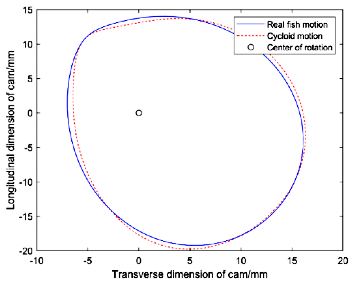
According to Equation (6), two cam profiles for the two periodical motions in Equations (1) and (2) could be obtained, as shown in Figure 2.
In Figure 2, we show the theoretical profiles of the cams that achieve the two wave motions. The cams can rotate around the center of rotation. The robot fish is equipped with these two cams to realize the movement of real fish and cycloid movement.

3. Kinetic Analysis

The power for driving the bionic robot fish was derived from the torque provided on the single joint via the motor. The double-cam mechanism transmitted the torque to the force acting on the rear part of the fish robot (point B in Figure 1); this caused the caudal fin to oscillate from one side to another. The motion of the caudal fin propelled water, thereby driving the movement of the fish robot. The propelling force in the forward direction of the fish body made the fish body swim forward. A dynamic analysis was performed when the caudal fin propelled water, as shown in Figure 3. In the subsequent experiments, we need to compare different wave motion forms under the same oscillation frequency, which naturally requires the same oscillation frequency variation range of the two wave motions. Due to the different force conditions of the two motion patterns, the requirements for the motor torque are also different. For this reason, we will perform a kinetic analysis on the maximum input torque required under the two motion patterns.
It is very difficult to analyze and calculate the irregular surface of the fish, so that some assumptions need to be added [19]. Here, we assume that the force acting on the skin of the fish is equal to the projected surface of the water-facing surface during the fish’s swing, that is, a straight line in the top view, as shown in the figure below.
There are two states in the period of fish tail swing. One is when the caudal fin swings to both sides from the middle position (x-axis), as shown in Figure 3a. At this moment, the caudal fin moves in a circular arc, and the swing speed of the caudal fin can be simplified as v in the vertical direction. It can be expressed as v = ϑ l p . lp is the length of the swinging part of the caudal fin. It is assumed that the swimming speed of robot fish is U at 4 Hz swinging frequency. Then, the speed of the fish tail in the global coordinate oxy is:
V f = ( U + v sin ϑ ) 2 + ( v cos ϑ ) 2
Then, the lift and resistance of the fish tail in the water can be estimated using Equations (8) and (9), respectively.
F 1 = 1 2 C 1 ρ S v f 2
F d = 1 2 C d ρ S v f 2
In the above, C1 and Cd is the lift coefficient and resistance coefficient. Additionally, ρ is the density of the water. S is the soaking area of the fish tail, ignoring the deformation in the process of movement, and was estimated according to the model. It was assumed that Φ was the angle between V f and U, denoted as follows:
Φ = arctan v cos ϑ U + v sin ϑ
Then, the angle between the lift F1 and tailstock lp was Φ = π 2 ϕ ϑ . Therefore, the moment of the caudal fin in each quarter period of swinging from the middle position to both sides can be calculated as:
M d = F 1 l p | sin Φ | + F d l p | cos Φ |
Figure 3b shows that the caudal fin swing back to the middle position (x-axis) from both sides. Similar to the approach above, V f and ϕ were calculated as follows:
v f = ( U v sin ϑ ) 2 + ( v cos ϑ ) 2
ϕ = arctan v cos ϑ U v sin ϑ
The angle between the lift F1 and tailstock lp was Φ = π 2 ϕ + ϑ . The moment of the caudal fin in each quarter-cycle of swinging back to the middle position from both sides could be calculated using Equation (11). In this way, we obtained the resistance moment that needed to be overcome in the entire period of the caudal fin swing. The torque was obtained by the motor driving the follower through the cam. Equation (14) is obtained from the law of fixed-axis rotation.
M q + M d = J α p
Here, Mq is the torque of cam to the follower, and J is the moment of inertia of the tail; α p is the angular acceleration of the tail. The angle between C-O and C-A, in Figure 1, is represented as γ and expressed as follows:
γ = arcsin L sin ( φ + φ 0 ) L 2 + l 2 2 L l cos ( φ + φ 0 )
According to the position relationship in Figure 1, the driving torque of the motor to the cam can be obtained as follows:
M = M d sin ( | π 2 γ + α | ) L 2 + l 2 2 L l cos ( φ + φ 0 ) l cos α
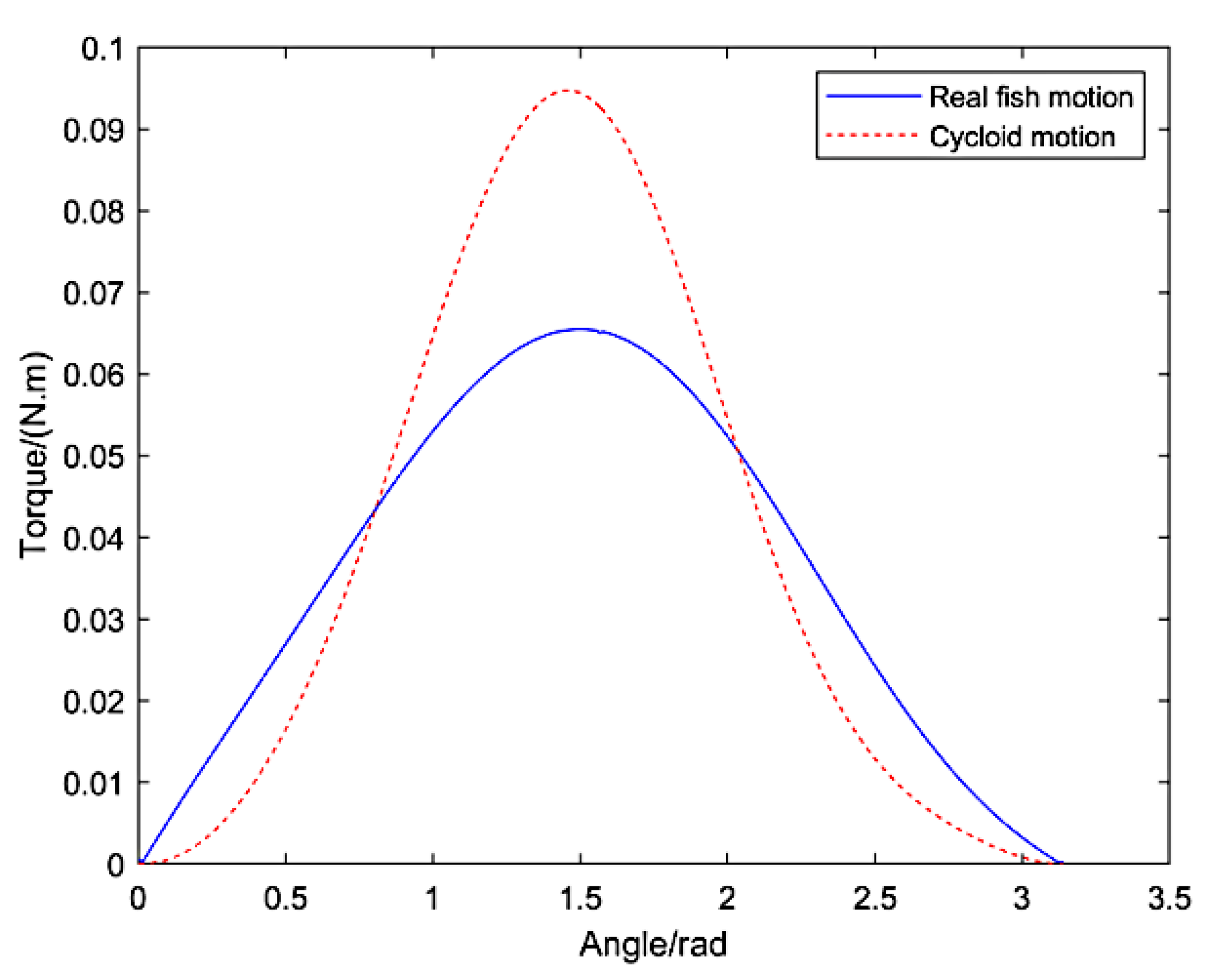
After the parameter values in the equation were given, the driving torque of the motor was drawn, as shown in Figure 4.
As shown in Figure 4, to ensure that the robot fish reached the same swimming speed under the two motion laws, the peak torque output of the motor under the cycloid motion law was higher than that under the real fish law. The curves in the figure were integrated to solve for the work done by the motor. The work under the real fish motion law was 0.1141 J, and that under the cycloid motion law was 0.1228 J. When comparing the two motions, it can be seen that the robot fish requires less energy to reach the same speed under the real fish law. Through the dynamic analysis of the robot fish and solution of the motor output torque, required to reach the same swimming speed under the two laws, it can be concluded that the performance of robot fish is better under the real fish motion law. In addition, the swimming performance of the robot fish is affected by the motion laws.

4. Structural Design and Fabrication of the Bionic Robotic Fish

The structure of the robotic fish was designed based on the shape of the crucian carp, as shown in Figure 5. The overall size of the robot fish was 320 × 65 × 130 mm, and it weighed 1.1 kg. A sealing groove was designed to connect the anterior and rear parts of the fish robot to avoid water leakage. The material of the fish head (including the head and the anterior part of the body) was UV curable resin, which was fabricated using 3D printing technology. A brushless DC motor (Maxon DCX 32L motor with a GPX32A reducer and Escon Module50/5 servo controller, parameters are shown in Table 2), battery (2000 mAh), and control system were installed in the anterior part of the fish robot. The torque output of the motor was transmitted to the cam via a pair of bevel gears. The cam drove the follower to swing, corresponding to its profile, and the end of the follower was pinned on the rear part of the fish robot. The fish tail (including the rear part of the body, caudal peduncle, and caudal fin) was made of nylon, which has good flexibility, and the tensile modulus was 1600 mpa, while the bending modulus was 1300 mpa. The stiffness of the caudal peduncle could be modulated by changing the sizes of the upper and lower “spines.” The “ribs”, connected on the “spine”, could support the fish skin. A lithium battery was used for the power supply, and the power supply voltage was 24 V. To make the system compact and simple, an Arduino Nano board, based on ATmega328, was selected as the low controller, where Bluetooth and wireless communication modules were embedded. Based on receiving signals from a high controller, a pulse width modulation signal was used to control the rotation of the motor at the desired frequency. There was a hole in the lower part of the fish head, leading to a wire that acted as a switch. When the fish was in water, the circuit was connected; when it left the water, the circuit was cut off.

5. Experimental Test and Results

To verify the performance of the proposed fish robot, experiments were conducted on the fish robot’s swimming with two types of double-cam mechanisms. The swimming speed of the robotic fish was also investigated at different frequencies of the caudal fin swing and under different motion trajectories. The experimental platform comprised of the developed robotic fish prototype, a pool, and a camera. The size of the pool was 3.6 × 2 × 1 m. The camera was suspended above the swimming path of the robot fish. In addition, there were coordinate grids in the pool. The time interval and moving distance of the robot fish were extracted from the video of the stable swimming state (set the frequency and amplitude of fish tail swing to be constant, when the fish swimming speed does not change significantly after a period of time) of the robotic fish, and the swimming speed of the fish was calculated.
Figure 6 shows a series of photos, derived from a video, in which the robotic fish swims in one cycle during stable swimming. The frequency of the tail fin swing is 4 Hz, and T represents the swing period. From the experimental results, it can be seen that the robotic fish can achieve stable swimming, and that the swimming posture is similar to that of real fish, such as the fish in the video above [18].

5.1. Influence of Motion Law on Swimming Speed

The swimming performance is influenced by the undulatory motion of the caudal fin, which can be modulated by the cam design. Meanwhile, the frequency of the undulatory motion is also a key factor in the swimming performance. In the experiments, we measured the variation in the swimming speed with the caudal fin swing frequency when the robot fish reached stable swimming in two motions. Figure 7 shows the velocity curves under two types of caudal peduncle stiffness; “BL” in the figure denotes the body length of the robotic fish.
It can be seen in Figure 7 that there are differences in the swimming speeds of the robotic fish under different motions. In the two groups of experimental data, the swimming effect of the robot fish under the real fish motion law is better than that under the cycloid motion law. This is consistent with the kinetic analysis results. In the most evident group of data, the results show that the swimming speed of the robot fish can reach 1.2 BL/s under the real fish motion law at the frequency of 4 Hz. However, at the same frequency, the robot fish only can reach 0.8 BL/s under the cycloid motion law. The swimming performance of the real fish motion is approximately 50% better than that of the cycloid motion. In addition, the Strouhal number can well-reflect the swimming efficiency of the robotic fish [20,21]. The results show that the Strouhal number of the robot fish under the real fish motion is lower than under the cycloid motion law, which indicates that the robotic fish is more efficient under the real fish motion. The experimental results show that, for a single-joint-driven robot fish with the same swing amplitude, even if the swing frequency is the same, different caudal fin motions will lead to different swimming performances.

5.2. Influence of Motion Law on Acceleration Performance

Through the above dynamic analysis, it can be seen that the ability of the robot fish to push water differs under different undulatory motions. Therefore, the influence of the motion law on swimming performance can be determined based on the resultant acceleration ability of the robot fish. In the experiment, we measured the acceleration process of the robot fish before reaching stable swimming under the two types of motion laws and different tail swing frequencies, as shown in Figure 8.
In the case of a high frequency of tail swing, the speed of the robot fish is high, duration of the acceleration process is short, and error of the measured data is large. If the frequency of the tail swing is too low, the acceleration process is relatively close, under the two types of motion laws, and the data gap is small. Therefore, the acceleration processes of the robot fish with tail swing frequencies of 3, 2.5, and 2 Hz, as well as the two motion laws, are selected for measurement. At all frequencies, the robot fish accelerates within 10 s and reaches a stable swimming stage. Figure 8a shows the acceleration change curve of the robot fish during the process of swimming. As can be seen from the figure, for robot fish with the same motion law, the acceleration at a high frequency is higher than that at low frequency during a period of time at the beginning of acceleration. This shows that with the increase in tail swing frequency, the stronger the acceleration ability of the robot fish, and the shorter the time to reach the steady speed. Under the same tail swing frequency, the acceleration ability of the robot fish is different under different undulatory motions. The acceleration ability of the robot fish under the real fish motion is better than that under the cycloid motion. As shown in Figure 8b, the time at which the robot fish reaches a stable swimming speed can be obtained. The speed of the robotic fish fluctuates slightly after reaching stable swimming, and the fitting curve always shows an upward trend. Therefore, 90% of the maximum speed of the robot fish is selected as the stable speed for comparing the arrival times. Under the real fish undulatory motion, the time to reach the stable swimming speed at frequencies of 3, 2.5, and 2 Hz are 2.5, 3.5, and 5.9 s, respectively. Under the cycloid motion, the time to reach the stable swimming speed at 3, 2.5, and 2 Hz tail swing frequencies are 3.0, 4.4, and 6.1 s, respectively. The acceleration ability showing the largest difference between the two motion laws shows that the real fish motion is approximately 20% higher than that of the cycloid motion. The experimental results again prove that, for a bionic robotic fish with the same amplitude of swing, different caudal fin motions will lead to different swimming performances, even at the same frequency of tail swing.

5.3. Influence of Caudal Peduncle Stiffness on Swimming Speed

We also explore the influence of the caudal peduncle stiffness on swimming speed, because we found that it has an inevitable influence on the swimming performances of fish robots. The thickness of the “spine” on the caudal peduncle was altered to change the stiffness of the caudal peduncle. The fish tails had thicknesses of 1, 1.5, and 2 mm, respectively. The swimming speeds of the two types of motions, with different stiffness values for the caudal peduncle, are shown in Figure 9.
It can be seen from Figure 9 that, under a low frequency, the robot fish with a low caudal peduncle stiffness has the best swimming performance and higher swimming speed. When the tail swinging frequency is in the range of 1 to 1.5 Hz, the swimming speed of the robot fish with a 1 mm caudal peduncle thickness reaches the peak value at approximately 0.3 BL/s, which is much higher than the values for the other two types of caudal peduncle thickness. However, with the increase in the tail swinging frequency, the swimming speed gradually decreases. After 3 Hz, the speed is 0, and the robotic fish can hardly swim. With the increase in the tail swinging frequency, the robot fish with a larger caudal peduncle stiffness shows a better swimming performance. When the tail swinging frequency is 4 Hz, the swimming speeds of the robot fish with 1.5 and 2 mm caudal peduncle thicknesses are much higher than that of the robot fish with a 1 mm caudal peduncle thickness. However, the swimming speeds of the robot fish with 1.5 and 2 mm caudal peduncle thicknesses are similar. This is because the highest swinging frequency is not high enough to distinguish the swimming speeds of the robot fish with the 1.5 and 2 mm caudal peduncle thickness. Overall, the effect of caudal peduncle stiffness on the swimming speed of robot fish is related to the swinging frequency. The speed of a robot fish with a low caudal peduncle stiffness is higher under a low swinging frequency, and the speed of a robot fish with a high caudal peduncle stiffness is higher under a high tail swinging frequency.

6. Conclusions

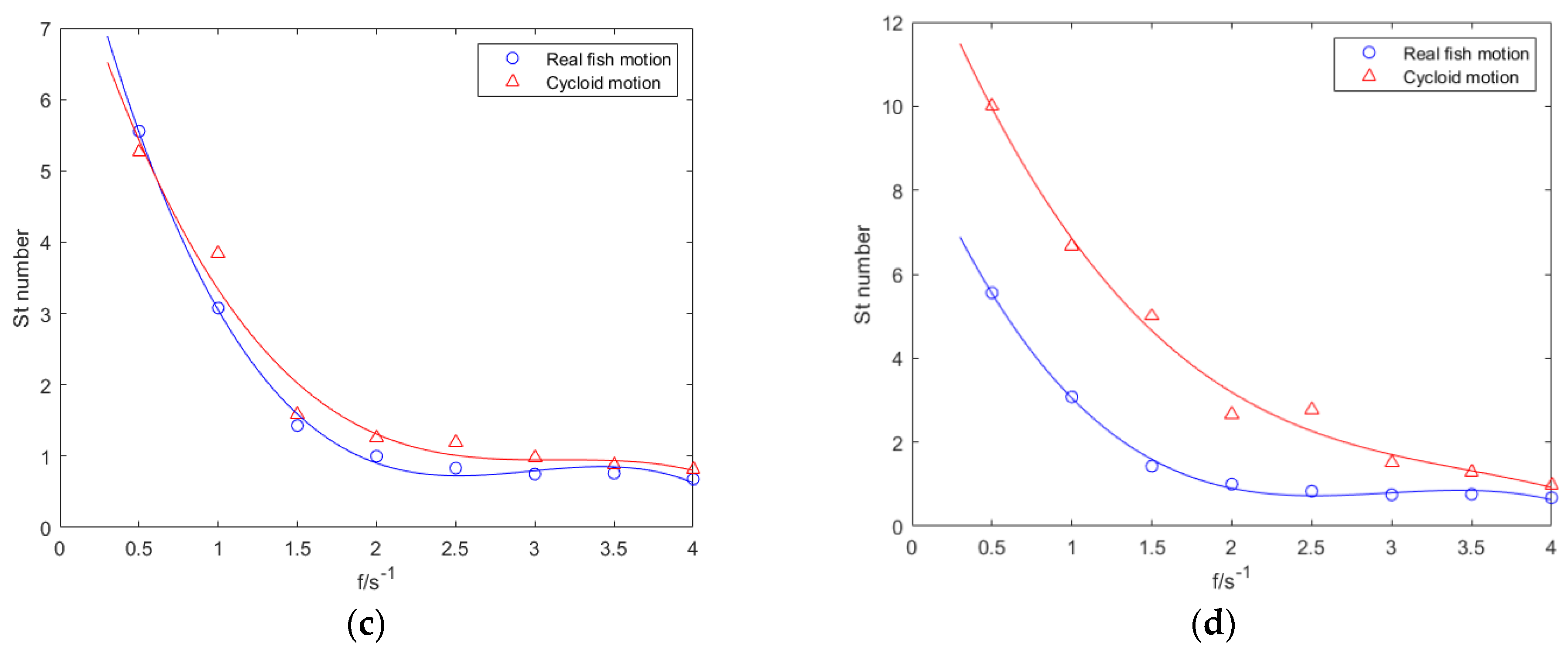
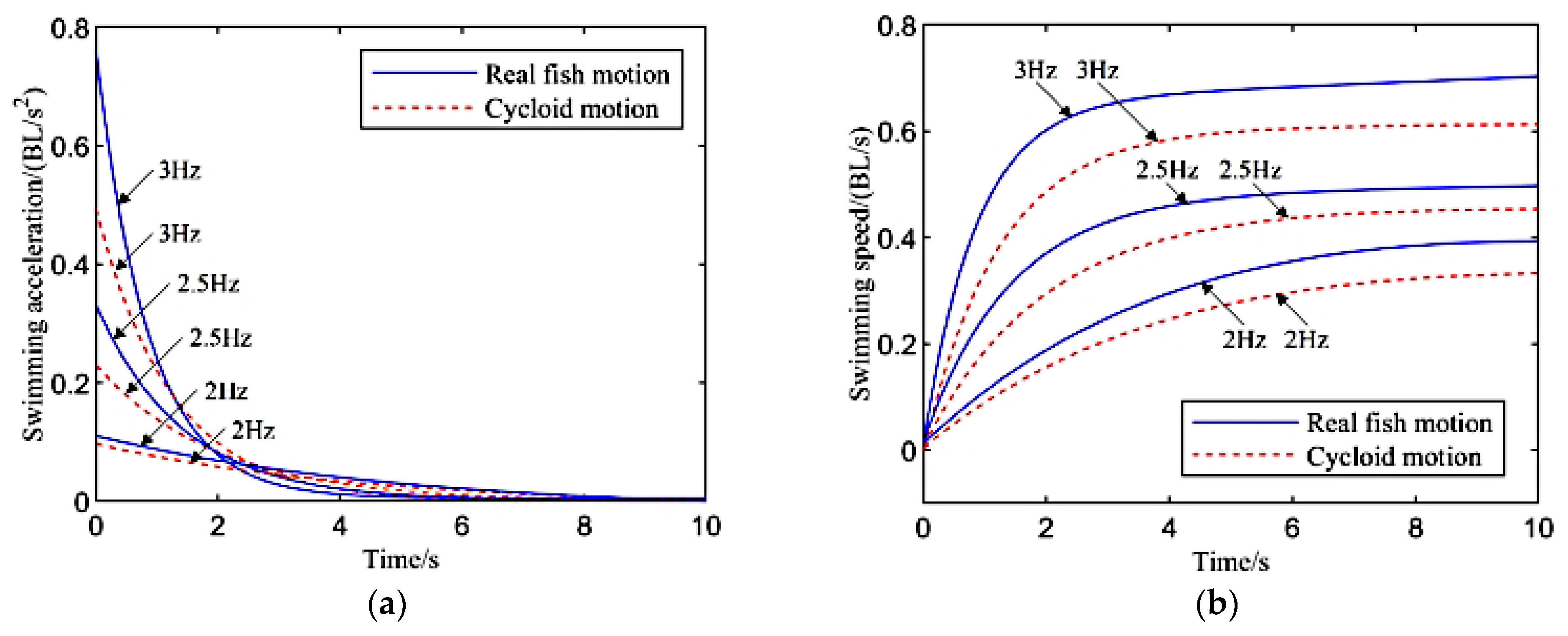
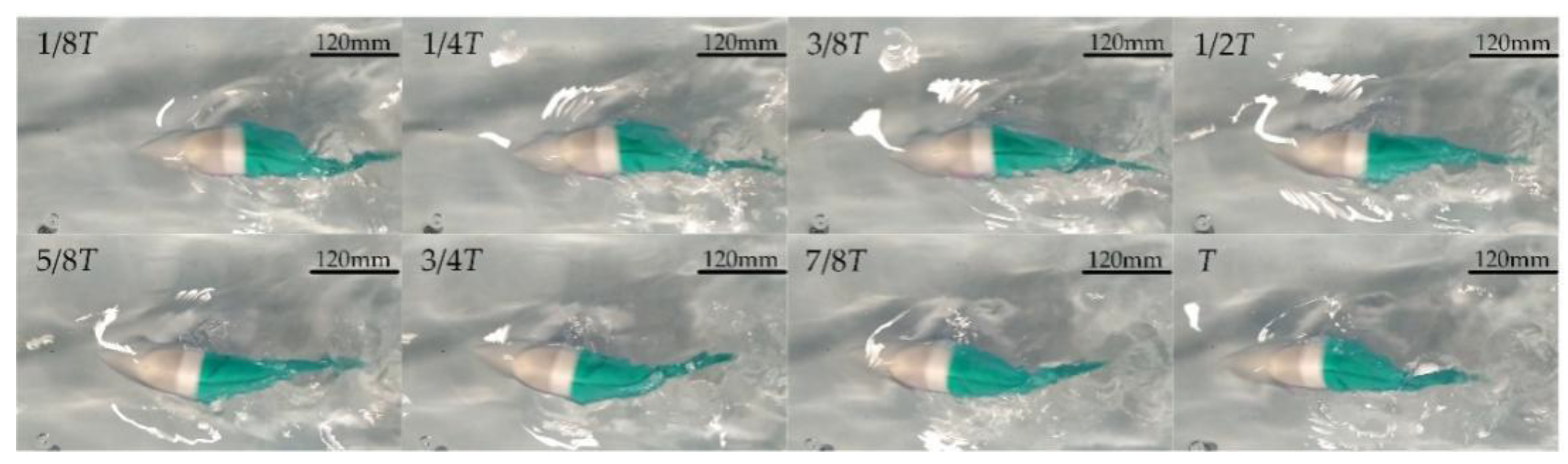
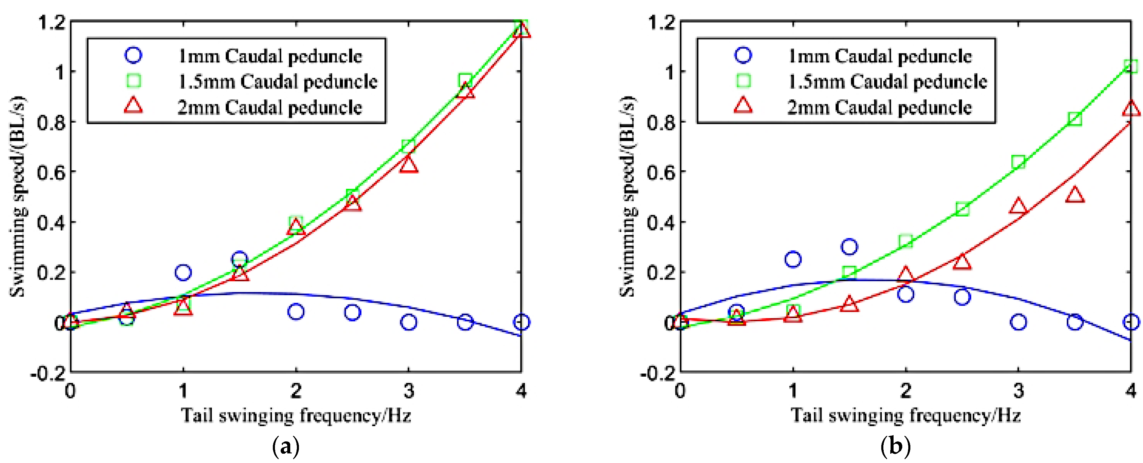
In this study, a novel double-cam fish robot was developed based on one active joint, where its caudal fin was driven by a newly proposed double-cam mechanism. Since the change of the cam profile can output a specific motion form, under the condition that the motor rotates at a constant speed and does not rotate in the same direction, this mechanism can help researchers modulate the undulatory motion of the caudal fin, so that the desired swimming performance can be obtained accurately. A dynamic analysis of the mechanism was conducted, and the results showed that different tail swinging motions affected the swimming effect of the robot fish. To verify the efficiency of the proposed mechanism, a prototype of a fish robot with two cams was developed; it was able to implement two motions, i.e., cycloid and real fish motion. By changing the thickness of the caudal peduncle in the robot fish, the stiffness of the structure was changed. The experiments were conducted using a fish robot with the two above-mentioned motions. The results show that the swimming speed of the robot fish is different for each undulatory motion. Under the current motor selection, the designed robot fish can achieve a tail swing frequency of 4 Hz and swimming speed of 0.38 m/s (1.2 BL/s). Regardless of the caudal peduncle stiffness, the swimming speed of the robot fish is faster when it reproduces the real fish motion of the caudal fin under the same frequency and amplitude of tail swing, and the maximum swimming speed can reach 1.2 BL/s. The robot fish with cycloid motion only reaches 0.8 BL/s. The maximum influence of the undulatory motion on the swimming performance reaches 50%. We discussed the influence of the undulatory motion on the acceleration ability of the robot fish. At frequencies of 3, 2.5, and 2 Hz, the acceleration ability of the robot fish is stronger when it reproduces the real fish motion of the caudal fin. In the early stage of swimming, the acceleration of the robot fish is higher at all frequencies when it reproduces the real fish motion of the caudal fin. Under the real fish motion, the times required for the robot fish to reach steady swimming are 2.5, 3.5, and 5.9 s at frequencies of 3, 2.5, and 2 Hz, respectively. Under the cycloid motion, the times are 3.0, 4.4, and 6.1 s, respectively. Compared the two types of motions, the acceleration time of the real fish motion is over 20% shorter than that of the cycloid motion at 2.5 Hz. The experimental results show that the performance of robot fish is better when it reproduces the real fish motion of the caudal fin, which is consistent with the kinetic analysis results. Furthermore, the swimming performance is also influenced by the stiffness of the caudal peduncle, which is related to the undulatory frequency of the caudal fin. The speed of a robot fish with a low caudal peduncle stiffness is higher under a low swinging frequency, and the speed of a robot fish with a high caudal peduncle stiffness is higher under a high tail swinging frequency.
In the future, fish robots will be tested in natural waters, such as the sea. Moreover, additional sensors will be embedded in this fish robot to explore the real environment of the sea.

Author Contributions

Conceptualization, Z.S.; methodology, Z.F. and Z.S.; writing—original draft preparation, Z.F.; writing—review and editing, R.K., D.R. and P.D. All authors have read and agreed to the published version of the manuscript.

Funding

This work was supported by the National Natural Science Foundation of China (NSFC) (grant number 51975401, 51875393), for a major consulting project of academy-local cooperation of Chinese Academy of Engineering (2021DFZD2).

Institutional Review Board Statement

Not applicable.

Informed Consent Statement

Not applicable.

Data Availability Statement

The data used in this study are openly available in the public domain.

Conflicts of Interest

The authors declare no conflict of interest.

References

  1. Costanza, R. The ecological, economic, and social importance of the oceans. Ecol. Econ. 2000, 1, 199–213. [Google Scholar] [CrossRef]
  2. Low, K.H. Locomotion and Depth Control of Robotic Fish with Modular Undulating Fins. Int. J. Autom. Comput. 2006, 3, 348–357. [Google Scholar] [CrossRef]
  3. Triantafyllou, M.S.; Michael, S.; Triantafyllou, G.S. An efficient swimming machine. Sci. Am. 1995, 3, 64–70. [Google Scholar] [CrossRef]
  4. Liao, J.C. A review of fish swimming mechanics and behaviour in altered flows. Philos. Trans. R. Soc. B Biol. Sci. 2007, 362, 1973–1993. [Google Scholar] [CrossRef] [PubMed] [Green Version]
  5. Breder, C.M. The locomotion of fishes. Zoologica 1926, 4, 159–297. [Google Scholar] [CrossRef]
  6. Wang, A.; Liu, G.; Wang, X.; Fu, B. Development and analysis of body and/or caudal fin biomimetic robot fish. J. Mech. Eng. 2016, 52, 137–146. [Google Scholar] [CrossRef]
  7. Sfakiotakis, M.; Lane, D.M.; Davies, J.B.C. Review of fish swimming modes for aquatic locomotion. IEEE J. Ocean. Eng. 1999, 24, 237–252. [Google Scholar] [CrossRef] [Green Version]
  8. Liang, J.; Zou, D.; Wang, S.; Wang, Y. Trial voyage of SPC-II fish robot. J. Beijing Univ. Aeronaut. Astronaut. 2005, 31, 709–713. [Google Scholar]
  9. Liang, J.; Zheng, W.; Wen, L.; Wang, T.; Xie, C. Propulsive and maneuvering performance of two joints biorobotic autonomous undersea vehicle SPC-III. In Proceedings of the 2009 IEEE International Conference on Robotics and Biomimetics (ROBIO), Guilin, China, 19–23 December 2010. [Google Scholar]
  10. Wu, W. Experimental Research on the Propulsion Performance of Carangiform Robotic Fish. Master’s Thesis, Deptartment Machenical School, University of Science and Technology of China, Hefei, China, 2010. [Google Scholar]
  11. Lachat, D.; Crespi, A.; Ijspeert, A.J. BoxyBot: A swimming and crawling fish robot controlled by a central pattern generator. In Proceedings of the First IEEE/RAS-EMBS International Conference on Biomedical Robotics and Biomechatronics, 2006. BioRob, Pisa, Italy, 20–22 February 2006. [Google Scholar]
  12. Wang, F.; Wang, Q.-L.; Wang, Z.-Y.; Dai, Y.-P. Cruising performance analysis and experiments of biomimetic robotic fish. J. Univ. Sci. Technol. Beijing 2012, 34, 80–84. [Google Scholar]
  13. Wang, J.; Tan, X. A dynamic model for tail-actuated robotic fish with drag coefficient adaptation. Mechatronics 2013, 23, 659–668. [Google Scholar] [CrossRef]
  14. Cheng, Y.; Shuai, C. Kinematic Analysis and Simulation of the One-Link and Fin-Driven Robot Fish. J. Ocean. Technol. 2018, 37, 7–14. [Google Scholar]
  15. Ge, L.; Li, Z. The speed optimization of robotic fish propelled by caudal fin. J. Lanzhou Jiaotong Univ. 2016, 35, 18–23. [Google Scholar]
  16. Zhu, J.; White, C.; Wainwright, D.K.; di Santo, V.; Lauder, G.V.; Bart-Smith, H. Tuna robotics: A high-frequency experimental platform exploring the performance space of swimming fishes. Sci. Robot. 2019, 4, eaax4615. [Google Scholar] [CrossRef]
  17. Costa, D.; Palmieri, G.; Palpacelli, M.-C.; Scaradozzi, D.; Callegari, M. Design of a Carangiform Swimming Robot through a Multiphysics Simulation Environment. Biomimetics 2020, 5, 46–56. [Google Scholar] [CrossRef]
  18. Zhong, Y.; Du, R. Design and Implementation of a Novel Robot Fish with Active and Compliant Propulsion Mechanism. In Proceedings of the 2016 Robotics: Science and Systems Conference, Ann Arbor, MI, USA, 18–19 June 2016. [Google Scholar]
  19. Vu, M.T.; Van, M.; Bui, H.P.; Do, Q.T.; Choi, H.S. Study on dynamic behavior of unmanned surface vehicle-linked unmanned underwater vehicle system for underwater exploration. Sensors 2020, 20, 1329. [Google Scholar] [CrossRef] [Green Version]
  20. Maertens, A.P.; Triantafyllou, M.S.; Yue, D. Efficiency of fish propulsion. Bioinspiration Biomim. 2015, 10, 046013. [Google Scholar] [CrossRef] [PubMed] [Green Version]
  21. Piskur, P.; Szymak, P.; Przybylski, M.; Naus, K.; Jaskólski, K.; Żokowski, M. Innovative energy-saving propulsion system for low-speed biomimetic underwater vehicles. Energies 2021, 14, 8418. [Google Scholar] [CrossRef]
Figure 1. Schematic diagram of the proposed double-cam mechanism.
Machines 10 00190 g001
Figure 2. The two cam profiles for achieving real fish motion and cycloid motion.
Machines 10 00190 g002
Figure 3. Force analysis of undulatory motion of fish robot: (a) caudal fin swings to both sides from the middle position (x-axis); (b) caudal fin swing back to the middle position (x-axis) from both sides.
Machines 10 00190 g003
Figure 4. The driving torque for each motion.
Machines 10 00190 g004
Figure 5. The structural model of the proposed robotic fish.
Machines 10 00190 g005
Figure 6. Sequence photos of robotic fish swimming.
Machines 10 00190 g006
Figure 7. Velocity and St number of the fish robot when it swims in two motions at different frequencies. (a) Velocity of 1.5 mm-thick caudal peduncle. (b) Velocity of 2 mm-thick caudal peduncle. (c) St number of 1.5 mm-thick caudal peduncle. (d) St number of 2 mm-thick caudal peduncle.
Machines 10 00190 g007aMachines 10 00190 g007b
Figure 8. Acceleration ability of robotic fish under different undulatory motions: (a) the acceleration during swimming; (b) the velocity during swimming.
Machines 10 00190 g008
Figure 9. Swimming speeds of three types of motions with different stiffness of the caudal peduncle: (a) real fish motion; (b) cycloid motion.
Machines 10 00190 g009
Table 1. The dimension parameters of the double-cam mechanism.
ParameterValue
Center distance L/mm20
Length of pendulum rod l/mm18
Radius of base circle of cam Rb/mm10
Roller radius Rr/mm4
Table 2. Parameters of the DCX 32L motor.
ParameterValue
Norminal voltage U/V24
Normial speed n/rpm453
Normial torque T/NM
Normial current I/AReduction ratio
0.57
2.875/3:1
Publisher’s Note: MDPI stays neutral with regard to jurisdictional claims in published maps and institutional affiliations.

