1. Introduction
To reduce uncertainties early in product development, it is necessary to validate the product, which requires knowledge about the behavior of the system [
1,
2,
3]. The necessary system knowledge can be determined by experimental investigations with prototypes in powertrain test benches, whereby non-existent components must be simulated [
2,
4].
Frontloading can shorten development times in product development and avoid late design changes [
5,
6]. In the industry, validation is very important, as is evident from the wide range of testing and validation activities.
For the validation of product series, problems result because, often, not all subsystems are available for early experimental investigations. Validation can, therefore, only be postponed to later phases in the development process, or be carried out via simulation.
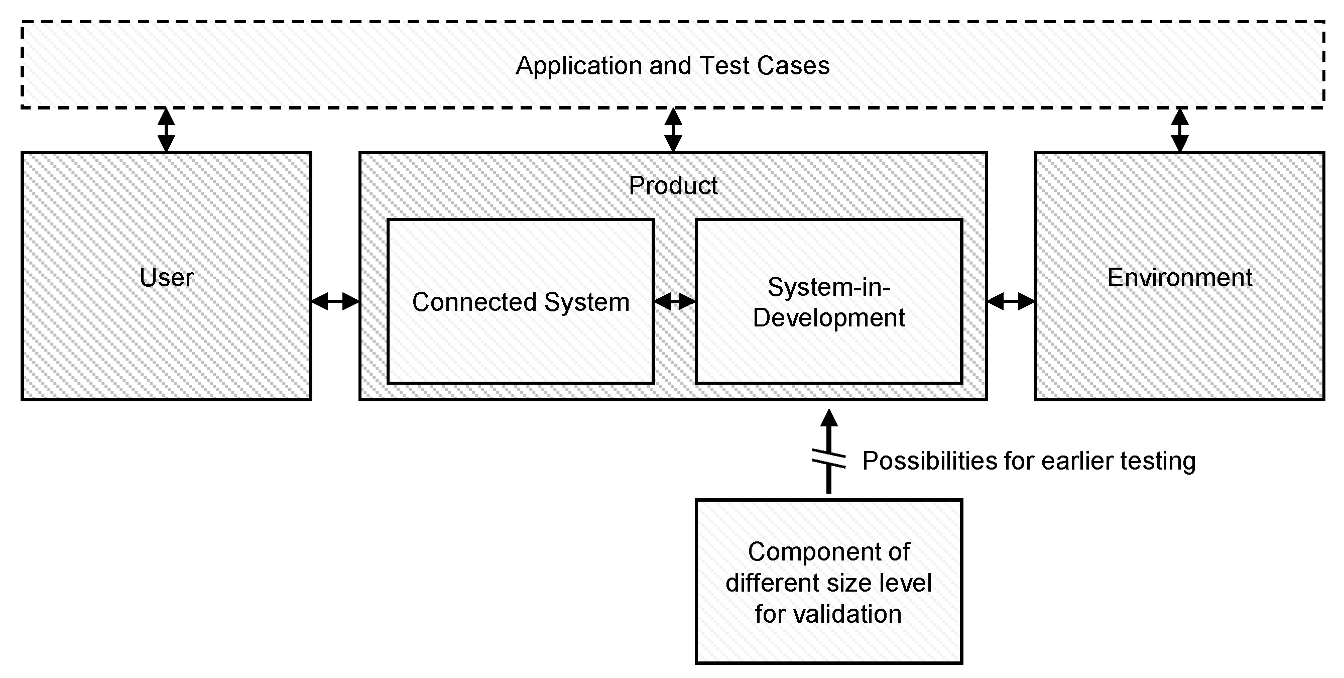
Especially in early development phases, the consideration of interactions is a challenge, especially if not all components and subsystems of the product are available for experimental investigations (see
Figure 1). Investigations into the overall system with realistic conditions are, thus, difficult.
A challenge in the early validation of powertrain components is the suitable integration of powertrain components into the overall system to map the interactions.
For practical testing and validation activities, it is important to integrate the system under investigation into the overall system. The XiL approach can be used for this purpose [
7,
8,
9]. The X-in-the-Loop (XiL) approach enables functional testing of a component or subsystem (System-in-Development, abbr. SiD) in test benches by integrating the remaining subsystems as physical or virtual models (as Connected Systems) [
3,
7,
8,
10]. Opportunities for early testing are provided by the use of early prototypes instead of using serial parts. Often, only subsystems of different size levels can be used for early validation as prototypes, for instance in wind tunnel experiments [
11] (see
Figure 1).
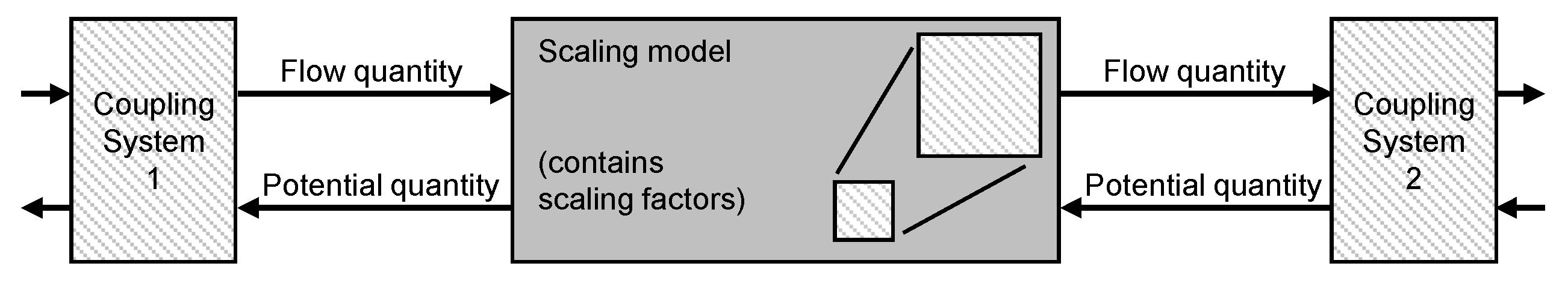
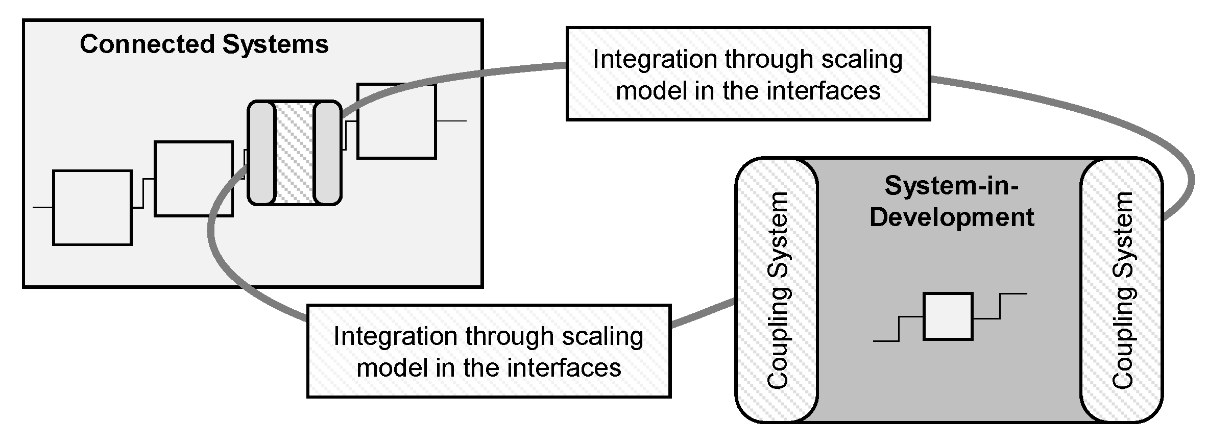
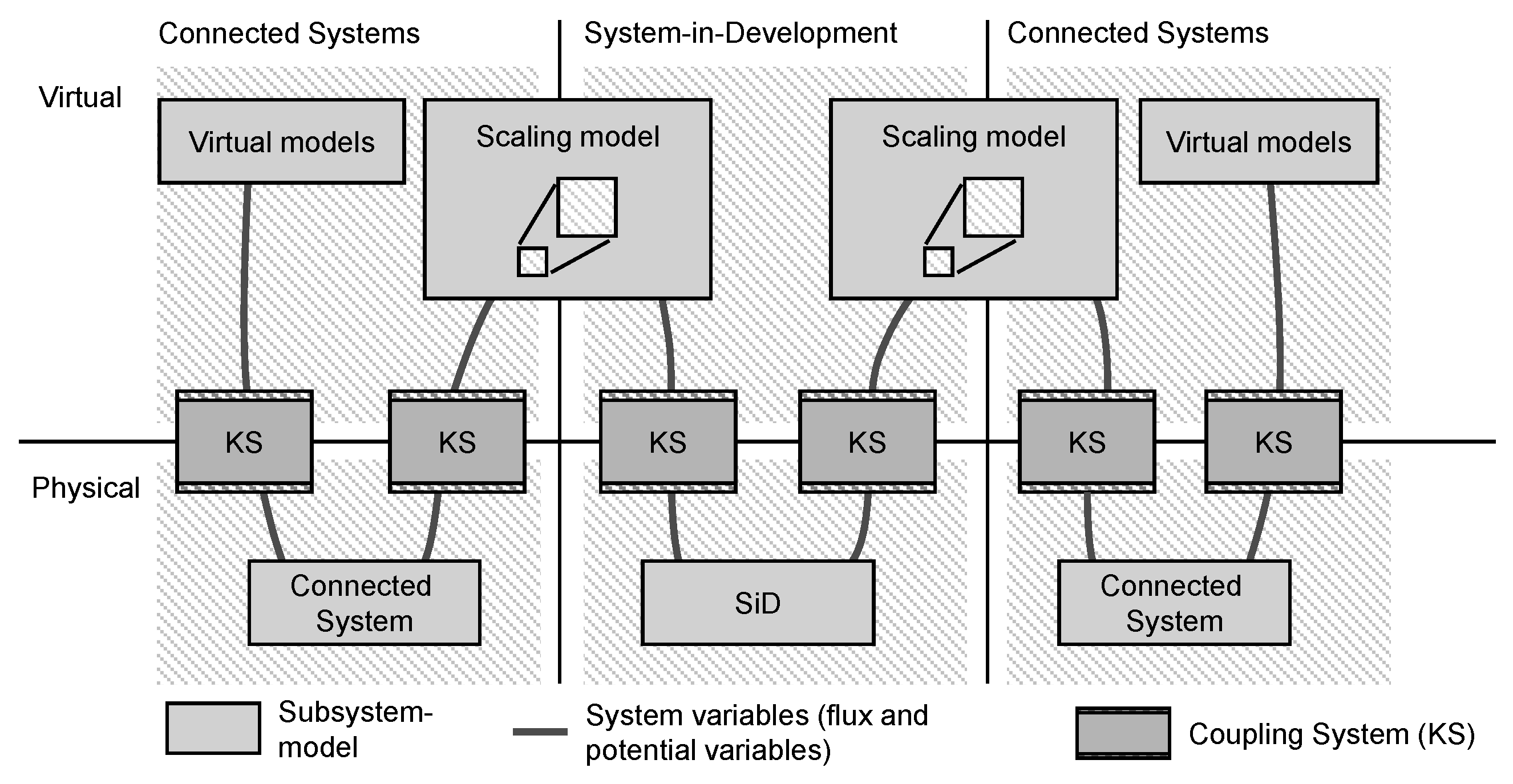
If only subsystems of a different size can be used as prototypes, an adaptation of the investigation test bench is necessary. For the integration of scaled prototypes in the context of X-in-the-Loop investigations, adapted coupling systems are required. The integration can be done by coupling systems (
Figure 2). Coupling systems can allow the integration of geometrically scaled drive components in X-in-the-Loop investigations.
Coupling Systems and Scaling Models to Support Validation
Coupling systems are used for the integration of powertrain components. These coupling systems connect the component or subsystems under investigation in test benches with the interacting subsystems, which are either physical or virtual. The virtual coupling of subsystems on the test bench is used in distributed validation to couple several test benches across different locations.
Approaches also exist in the implementation of virtual shafts to connect testbeds. The theoretical background is well known in control engineering. A review of the last 20 years on the synchronization of multi-motor systems was presented by Perez–Pinal et al. [
12]. It is important to consider interactions in the coupling of torque and speed between the interacting systems.
Andert et al. use an approach to connect different subsystems of drive trains by a virtual shaft [
13]. The aim of this approach is to couple test facilities for components to a virtual powertrain test bench with a control logic that emulates a mechanical shaft connection. The superimposed controller synchronizes speed and torque like a rigid shaft connection with low inertia and high stiffness. This infrastructure allows a flexible configuration of hybrid and conventional powertrains with virtualized interaction [
13].
In addition, there is an approach for the adaption of power quantities within the virtual coupling [
14,
15]. The integration of differently scaled subsystems, which are to be tested simultaneously on a test bench, is presented. Within the coupling systems, the power quantities are adapted to the scaled subsystem. Adaption can be made for the power quantities of a rotatory motion, for torque and angle of rotation [
14].
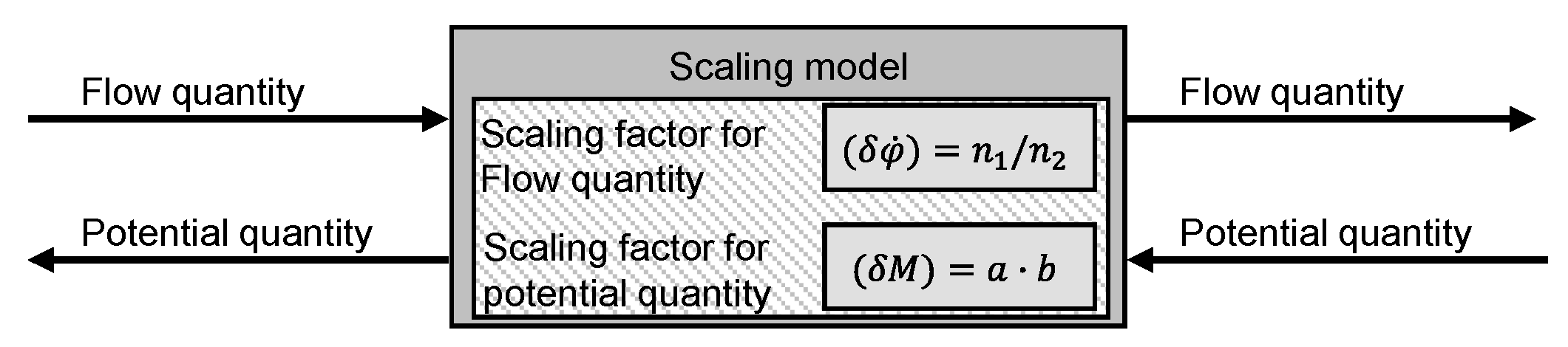
The virtual coupling enables the modification of mechanical quantities in a rotational powertrain by scaling. The general structure of this virtual coupling is shown in
Figure 2. Studies with scaled subsystems also exist in the field of mechatronic systems and wind turbines [
16,
17,
18,
19,
20,
21].
Two examples of previous research [
14,
15] demonstrate virtual coupling and the integration of performance scaling within XiL test benches. In an initial investigation, scaling of rotational variables was used to enable simultaneous testing of powertrain subsystems with different scaling on a XiL test bench. This was demonstrated using the example of different performance scaling of the spring preload force of an overload clutch from a powertrain.
The results of the investigation [
14] show that the rotational mechanical quantities can be adapted using scaling laws obtained from a similarity analysis. The scaling model makes it possible to adapt the system quantities between the subsystems and, thus, predict the behavior of the product, even if differently scaled subsystems were used on the XiL powertrain test bench.
In a further investigation [
15], the scaling of the performance quantities was considered through a simulation using the example of an aerospace actuator. The aim was to take into account differences in size and, thus, different load capacities, and to compensate for them with a scaling model. Using the example of a torque limiting clutch from a geared rotary actuator out of an aircraft, the influences of the rotational inertia of the drive shaft on the scaling are analyzed in a simulation study. The determining influence is taken into account by the integration of virtual inertia within the scaling [
15].
In previous XiL-investigations [
14,
15], the individual differing properties of the scaled powertrain components were already taken into account in the scaling model.
The problem is that an analysis of the scaling model for early investigation of geometry variations has not yet been performed in XiL-experiments. The following investigation addresses the question of whether the scaling enables a functional investigation of geometrically scaled drive components in X-in-the-Loop investigations.
The aim of the paper is the functional investigation of geometrically scaled drive components by integrating scaled prototypes in an X-in-the-Loop test bench. Using the example of an overload clutch with detents, component variants of different size levels are investigated in tests with performance scaling. For this purpose, an exemplary adaptation of the geometry of the overload clutch and its validation with the performance scaling is considered.
The following hypothesis is formulated: “The scaling enables the geometry testing of scaled components. Using a scaling model in X-in-the-Loop test bench, geometrically scaled drive components can be tested for functional properties, and geometry variants can be evaluated for product engineering.”
For the investigation, a scaling model is considered concerning the early investigation of geometry variants in the XiL test stands. Using the example of an overload clutch, two different geometry variants are examined in scaled component tests, taking into account the interacting system.
2. Methods of Scaled Virtual Coupling for XiL-Test Bench
This chapter describes the approaches used to perform scaled component tests considering the interacting system. First, the used approach is shown in general, and implementation in a XiL test bench is presented. Based on this, the derivation of the scaling model to adapt the rotational quantities between size variants of a cordless screwdriver is presented.
2.1. Approach and Theory of Virtual Coupling
To integrate the scaled drive train components, an adaptation of the transmitted power within the coupling systems is necessary. The following approach (see
Figure 3) can be used as a basis for integrating the scaled prototypes into the overall system and an investigation in XiL test benches.
The approach for adapting power between interconnected subsystems (
Figure 3) is based on the virtual coupling [
23] and virtual shaft concepts [
13].
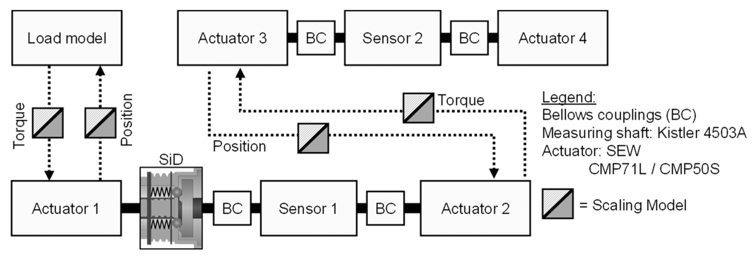
Virtual coupling refers to the decoupling of mechanically connected subsystems in a powertrain test bench and their coupling via virtual connections. The approach can be used to set up XiL test benches for early validation using reduced-size prototypes. The following subsystems shown in
Figure 4 are necessary for the implementation:
System-in-Development (SiD): Is the subsystem to be developed whose functionality is to be verified.
Connected system represents the remaining subsystems of the system under development (SiD). It is physically present and forms the remaining system model. This is needed to represent the interactions with the SiD and to integrate it into the overall system.
Coupling systems connect the Connected System and the System-in-Development. With the help of scaling models, they translate physical performance quantities into virtual system quantities and vice versa.
The structure (
Figure 4) can be used for the implementation of system-specific test benches. From this, an example of XiL architecture for scaled tests (
Figure 4 can be derived. The implementation for scaling the rotational mechanical quantities is shown below.
In general, the system-in-development (SiD) is connected to the remaining system only via coupling systems (KS) and the virtual domain. The coupling systems consist of sensor-actuator systems that adapt the system quantities from virtual to physical quantities and in reverse. Servo motors are used as actuators, which are supplemented by additional sensors to detect torque and speed. The flow and potential quantities are continuously exchanged between the coupling systems in real-time and can be adapted by the scaling models. These coupling systems allow the adaptation of the rotational power quantities through a scaling model. The integration of scaling via virtual coupling is shown in
Figure 5.
The selection of actuators and control requirements depends on the dynamic requirements of the investigation. For dynamic systems with interactions between the interacting systems, the requirement of the real-time capability of the virtual coupling has to be considered when selecting the sensor-actuator systems. Virtual coupling can be evaluated using the criteria shown in Gwosch et al. [
22]. A scaling model can then be integrated via the virtual coupling to adapt the mechanical performance variables.
2.2. Example System and Component Variants of the Overload Clutch
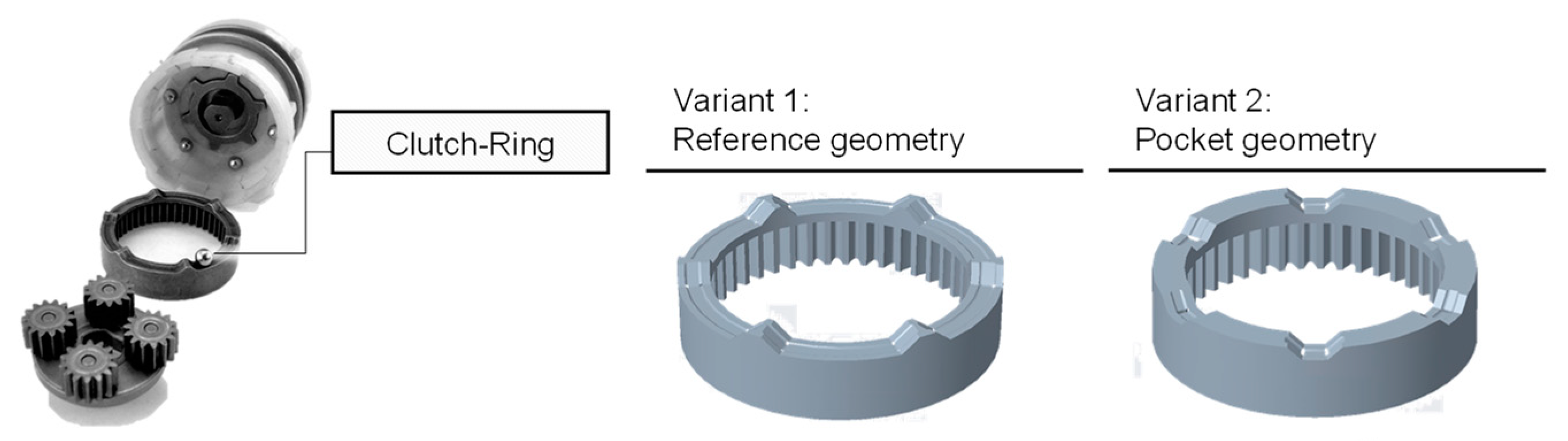
The scaling model is investigated in component tests to evaluate geometry variants of geometrically scaled drive components. The influence of the different geometry variants is investigated in both scaled and unscaled component tests. For this purpose, two prototypically implemented component variants of the clutch ring are examined concerning the release characteristics of the overload clutch on a XiL test bench.
To investigate the release characteristics, key values in the torque curve of the output shaft are considered. The scaled geometry variants are integrated via virtual coupling systems and scaling to enable scaled component tests, taking the rest of the system into account. Via the scaling, an adaptation of the torques and speeds between the considered subsystems is possible.
Two clutch systems from cordless screwdrivers are used as an example system. A cordless screwdriver in the 10.8-Volt version (Cordless screwdriver GSR 10 8 Li of the power tool manufacturer Robert Bosch GmbH [
24]) and a cordless screwdriver in the 18-Volt version (Cordless screwdriver GSR 18-2 Li of the power tool manufacturer Robert Bosch GmbH [
25]) is used here. Both clutch systems use the same operating principle but differ in terms of the size level, which is related to the battery voltage (size level 10 V/size level 18 V).
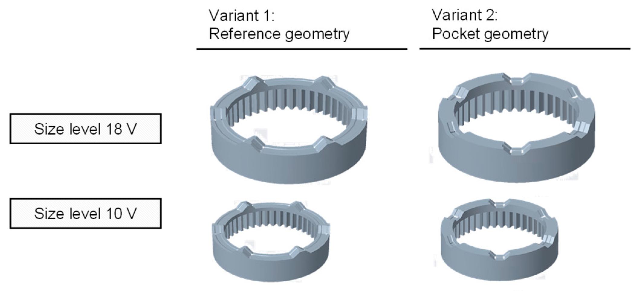
To test the formulated hypothesis, two variants of the clutch ring of a cordless screwdriver are investigated on a XiL test bench. The variants differ in the raceway geometry of the clutch ring (See
Figure 6). Variant 1 corresponds approximately to the original geometry of the series component, and is used as a reference. Variant 2 was adapted in geometry and contains a pocket geometry. Comparable geometries of the component variants have already been used by Gwosch [
26].
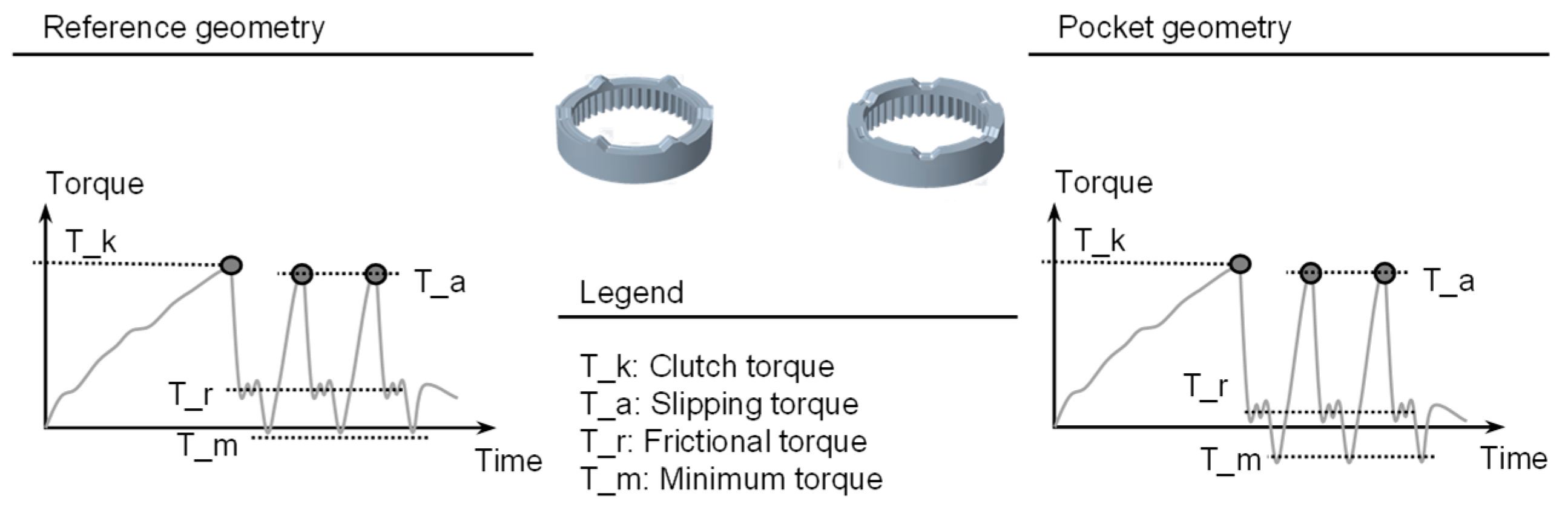
A theoretical consideration of the torque curve for active overload clutch is shown as a qualitative curve in
Figure 7 based on investigations of Gwosch [
26] and simulation results from Steck et al. [
27].
Description (based on research in [
26]) of qualitative progression: If the applied torque exceeds the clutch torque, the balls move over the detents of the clutch ring and the clutch disengages. The torque then drops. Repeating contact between the detent balls and the driver of the clutch ring causes further torque increases. The functional behavior depends on the geometric properties of the clutch and the dynamic behavior of the driveline. Gwosch showed in investigations an influence of the behavior depending on the raceway geometry [
26]. A deviating frictional torque is expected for the pocket geometry compared to the reference geometry.
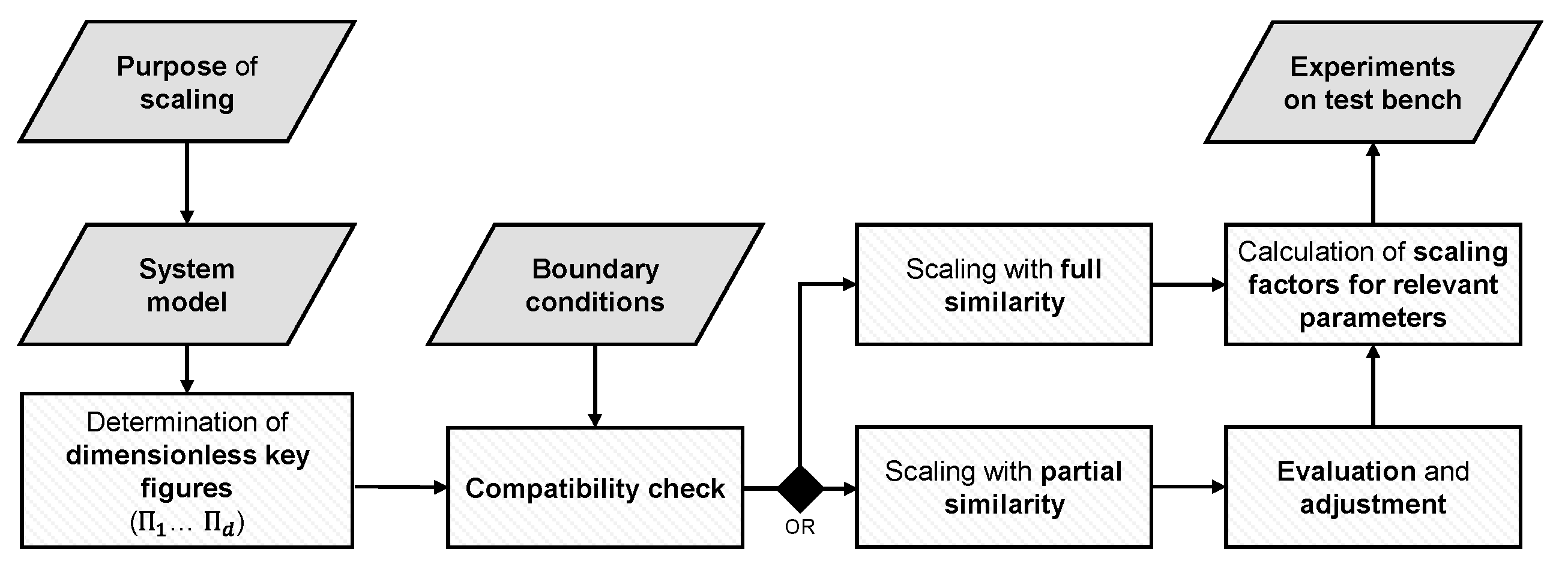
2.3. Derivation of Scaling by Similarity Ratios
Necessary for the derivation of the scaling (based on research in [
14,
15]) is a sophisticated model understanding, which takes into account all relevant parameters of the investigation target. Relevant parameters are based on the system understanding of the components under consideration and experimental investigations in the reference system, as well as the requirements for the component currently in focus and under development.
Based on these model differences, similarity mechanics and dimensional analysis can be used to derive the scaling factors. The general procedure is shown in
Figure 8.
For rotational mechanical systems, the mechanical parameters M, , and l can be used as the main variables of the system since they represent the model differences of the scaled and unscaled systems and the physical quantities in the virtual clutch. The rotational power variables are adapted depending on the scaling factors. Based on the scaling of the size step, an adaptation of the torques is performed, and additionally, the speeds between the subsystems are scaled.
Based on a modeling of the clutch, the relevant parameters, which are called the relevance list, were analyzed by dimensional analysis. The dimensions of the relevant parameters are classified according to the {MLT} system, the dimensions are mass (M), length (L), time (T) [
28,
29,
30]. The parameters
,
and
are used as main quantities of the system, since they represent the differences of the scaled and unscaled system.
The dimensionless ratios are calculated based on the dimensionless quantities and their relationships. The calculated ratios are then checked for consistency. In case of inconsistencies, not all dimensionless ratios can be considered, resulting in partial similarity.
For the coupling system study example, the scaling factors are derived below. The following
Table 1 shows the result of the dimensional analysis for the investigation of both size variants of the cordless screwdrivers. In this study, friction effects were not considered in the scaling models.
Result of the dimensional analysis. The parameters , , and (torque, angular velocity, and diameter) are used as the main quantities of the system since they represent the difference of the scaled and unscaled system and the physical quantities in the virtual coupling.
The two size levels of the clutches do not differ in terms of the used materials and the manufacturing processes. Due to the characteristics of the XiL test bench, the properties of the prototype, and the purpose of the scaling, the following boundary conditions are relevant:
The diameter of the clutch () is scaled by the factor . Thus, the ratio between the diameter () of the scaled and unscaled system is described by .
The height of the clutch ring () is scaled with . There is no complete geometric scaling of the size level. The height of the clutch ring is responsible for the preload of the spring and, thus, determines the clutch torque. This length is scaled with .
The torque is given by the spring force multiplied by the diameter of the clutch ring. As a result, the torque is scaled with
The transmission ratio is already a dimensionless key figure that describes the ratio of the number of teeth of the gears.
The speed is scaled by the factor . The differences in the transmission ratio determine the scaling of the speed.
Time scaling is not permitted. This is necessary to be able to represent the interactions between the subsystems. Therefore, a ratio between the time of the scaled and unscaled system is defined such that there is no scaling .
The same material should be used, i.e., there is no scaling for the material: . Since the same material is used for all tests, any differences that may occur in the friction condition are not taken into account.
The boundary conditions do not allow a complete geometric scaling, because the diameter and the height of the clutch cannot be scaled with the same factor. The verification of the ratios shows a discrepancy for the moments of inertia. Due to the partial similarity of the geometric dimension, the inertia of the clutch ring is not scaled to the same degree. Additionally, there is a discrepancy between the scaling of the inertia and the scaling of the moments of inertia. The external torque is scaled by the factor (
) while the moment of inertia is scaled by a different factor due to the different geometry. To account for the two states of the planetary gear in interaction with the clutch, the scaling of the speed is split. There are adaptations of the speed before and after the clutch. The check with the boundary conditions results in a partial similarity for these component tests in this publication. Finally, the following scaling factors result (see
Table 2).
The scaling factors and are used to calculate the power quantities (flow and potential quantities) on the test bench:
The scaling of the applied torque depends on the ratio of the coupling dimensions. From this follows the scaling of the torque with (
Scaling of the angular velocity is according to: (
The calculation of the performance variables (see
Figure 9) is performed within the control system in real-time during the operation of the test bench. The adapted mechanical quantities are then applied to the interacting subsystems in the coupling systems.
The scaling factors (given in
Table 2) are used to calculate the power quantities (flow and potential quantities) on the test bench. For implementation, the scaling factors are integrated into the virtual coupling at the test bench.
3. Experimental Setup
In the following, the test bench setup (experimental setup) for evaluating the scaling for geometry variation is shown. The implementation of the test bench is based on the approach presented in Chapter 2.1 Using clutches from two cordless screwdrivers as an example, the scaling model for investigating geometry variation is considered. In individual investigations, the clutch from one cordless screwdriver was used to evaluate the influence of geometry on the release behavior in scaled investigations.
This chapter presents the experimental setup of the scaled component tests to evaluate scaling. In addition, the component variations of the overload clutch are described. The series of tests for performing the scaled component tests on a XiL test bench is then shown. Based on the scaled component tests with different geometries, the analysis of the approach for the investigation of scaled geometries is carried out.
3.1. Test Setup
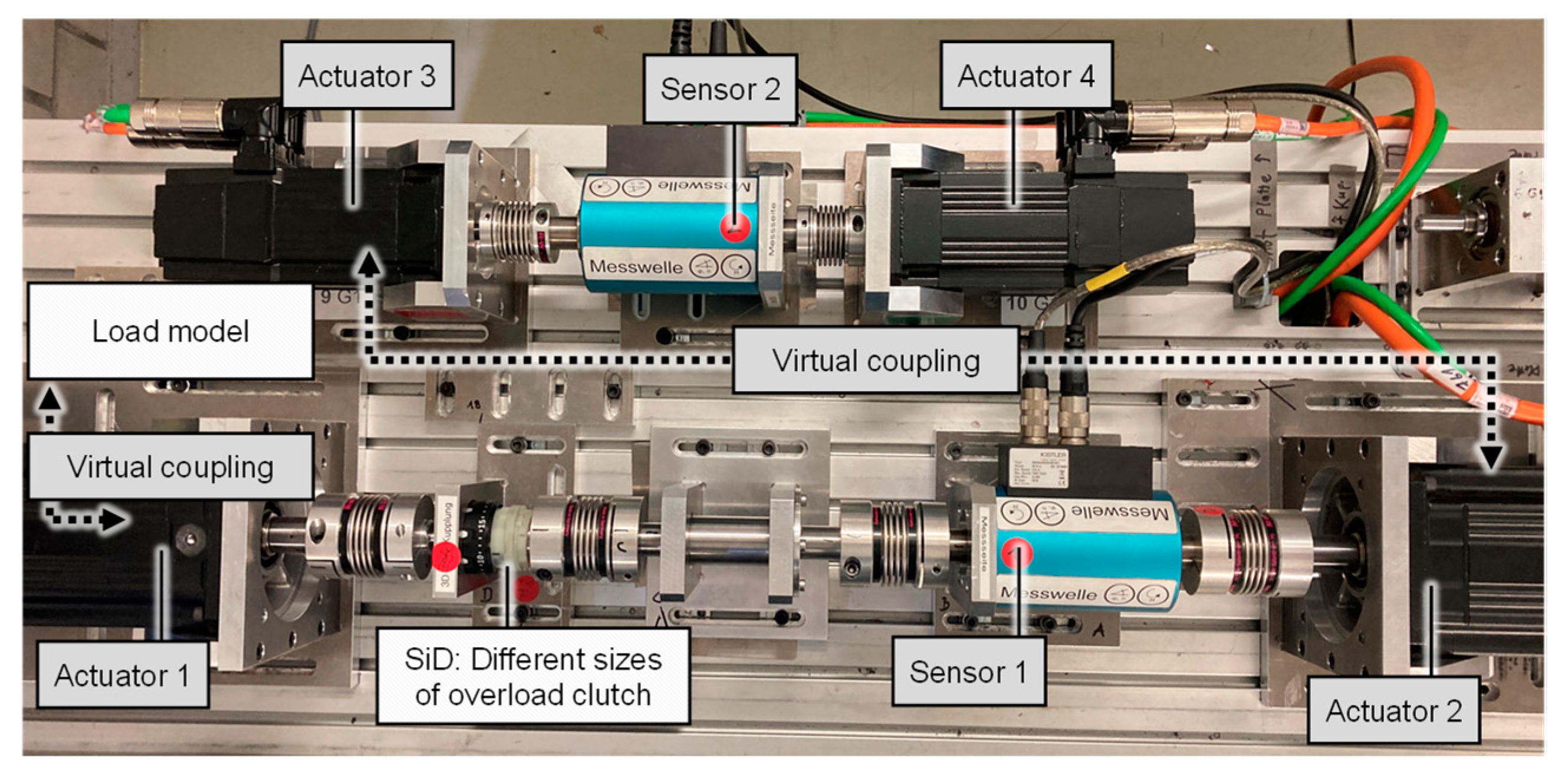
The test setup is based on the approach shown in Chapter 2.1. The component variants of the clutch rings can be inserted into the overload clutch on the test bench (
Figure 10 The investigation is exemplified on the scaled-components-in-the-loop (sCiL) test bench [
14,
15,
22] with the investigation setup shown in
Figure 11. The test bench is operated in closed-loop mode. The individual drive train systems can be positioned and aligned via standardized base plates. The accuracy and the real-time capability of the signal transmission must be taken into account. It is important that the influence of the coupling systems on the signal transmission is as low as possible, and that no negative deviations occur.
The investigations are carried out with a generic load model. The load torque is obtained from the angle of rotation via a constant load factor. The load model and the virtual models of the XiL-architecture can be considered as a digital twin. The speed of the drive shaft is used as the default value, which is kept at a constant value of 100 rpm after a ramp-up phase.
The scaling models are integrated within the virtual coupling between the Systems under Development. The coupling systems are realized with sensor-actuator systems and a centralized or decentralized control system. The implemented test setup is shown in
Figure 11.
3.2. Execution of the Component Tests
In Gwosch [
26], the component variants were manufactured from the material AlSi10Mg using an additive manufacturing process. In this publication, additively manufactured components made of polymer were used for geometry variants due to manufacturing restrictions. To be able to investigate the influence of the geometry variation, both geometry variants are produced using the same manufacturing process and the same material.
The clutch rings used in this investigation are shown in
Figure 12. Both component variants of the clutch ring are made of photopolymer (Photopolymer VeroWhitePlus from manufacturer Stratasys. Material properties are given in [
31].) by an additive manufacturing process. The raceway of the clutch ring was oriented upward during additive printing to realize a smooth surface. The geometry of the clutch rings was measured in terms of overall height before testing. Consideration of different manufacturing processes and material properties in the scaling is not part of this investigation.
The test series differ in terms of the used geometry variant and the used scaling model to adapt the performance quantities between the different scaled clutch to the environment. For the scaled tests (10 V Scaled), the small clutch (size level 10 V) is included in the scaled environment. The differences in power quantities are compensated for by the scaling model. This is compared to two experiments without a scaling model at two different size levels (size level 10 V and 18 V). The release characteristics of the two geometry variants are compared both in the scaled (size level 10 V Scaled) and unscaled experiments (size level 10 V and 18 V).
To evaluate the scaling model for the investigation of geometry variants, the following test series are carried out and compared concerning the release characteristics:
Unscaled component in unscaled environment (Standard case in size level 10 V)
Unscaled component in performance scaled environment (relevant case in scaled size level 10 V)
Size scaled component in scaled environment (Case for evaluation in size level 18 V)
These experiments are performed for two different geometry variants, so in total 6 different experiments. The coupling torque and the frictional torque are considered as evaluation variables of the release characteristics.
The characteristic values are plotted in
Figure 7. The selected evaluation variables are relevant for the derivation of target variables in the development since the safety function of the clutch depends on them. The filtered torque at measuring shaft 2 in
Figure 10 is selected as the measured variable. The test is repeated 21 times for each variant. A total of 126 tests were performed.
4. Results of the X-in-the-Loop Integration of Scaled Prototypes
In this chapter, scaled component testing is presented considering the rest of the system. This is then followed by the evaluation of the scaling for the early evaluation of design decisions.
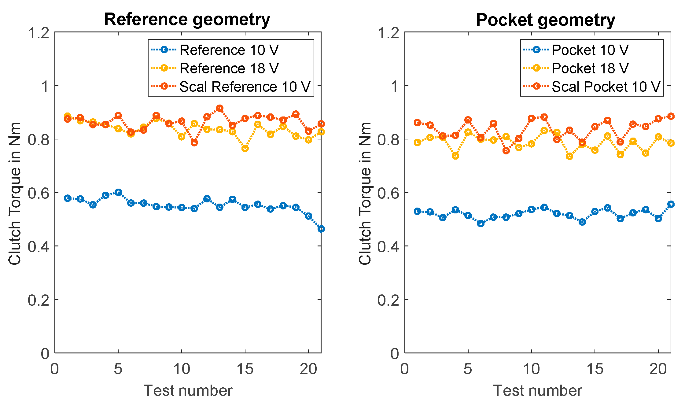
The results for the evaluation of the geometry variants are summarized in
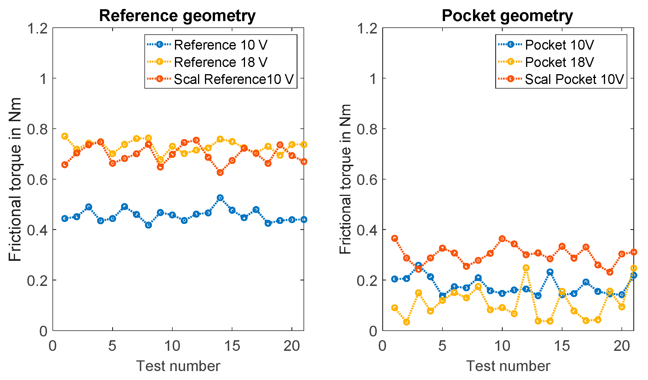
Table 3. It can be seen that the scaling model within the coupling systems allows an adaptation of the clutch torques of the different variants. For the frictional torque, the results show a difference between reference geometry and the pocket geometry.
Table 3 shows the mean values of the clutch torque and the frictional torque of the two geometry variants for measuring shaft 2.
To check the functionality of the scaling, the coupling torques were evaluated. The clutch torques of the reference geometry and pocket geometry are shown in
Figure 13. The mean value of the clutch torques is at a comparable level for the two variants. Here, there is a good agreement between the clutch torques of the scaled tests (10 V Scaled) and the tests of the size level 18 V. It is shown that it is indeed possible to adapt the coupling torques by scaling.
In addition, the characteristic value of the frictional torque was considered in the investigations. For the reference geometry, there is good agreement between the frictional torques of the scaled tests (10 V Scaled) and the tests of the size level 18 V. For the pocket geometry, the frictional torque is at a lower level for all size levels (see
Figure 14). For both geometry variants, some outliers can be identified (see
Figure 14).
In summary, there is a difference between the mean values of the frictional torque parameter for the reference geometry and the pocket geometry. At a comparable clutch torque level, the frictional torque of the pocket geometry is lower than that of the reference geometry. In the scaled tests, the frictional torque of the pocket geometry is also lower compared to the reference geometry. For the mean values of the frictional torque, there is a deviation in the comparison of the scaled investigation (10 V scaled) with the unscaled variant (18 V).
5. Discussion
In the following, the scaled component tests and the approach with a scaling model within the coupling system are discussed.
The hypothesis formulated at the beginning of this paper: “Scaling enables geometry investigations of scaled components. By using a scaling model in an X-in-the-Loop test bench, geometrically scaled drive components can be tested for functional properties and geometry variants can be evaluated for product development.” This is reviewed below.
The results in this paper show how scaling models support the XiL-investigation of geometry variants for scaled components.
For the example system of a clutch out of an electric screwdriver, the match between scaled investigations and non-scaled investigations is good for the evaluation variable of the clutch torque. By changing the raceway geometry of the clutch ring, the release characteristic of the overload clutch can be adapted and investigated in scaled experiments. These results confirm a dependence of the behavior on the raceway geometry similar to investigation results presented by Gwosch [
26].
It is not necessary to adapt the scaling to the geometry variants, provided that no additional physical effects (e.g., friction) become relevant as a result of the geometric changes, which are not currently taken into account. In scaled investigations, subsystems of different size levels can be used to test variants with different geometries for their functional performance.
The results of the scaled component tests confirmed an influence of the geometry on the frictional torque at the output shaft of the cordless screwdriver drive train. The scaled component tests show a deviation in the frictional torque of the pocket geometry compared with the reference geometry. The frictional torque here is well below the clutch torque. These differences show that not all effects responsible for this characteristic point in the torque behavior are taken into account in the scaling model. Due to the relatively low frictional torque, effects may be present here that are less important to the clutch torque. In the case of changing friction conditions during the rotational motion, it is therefore difficult to map the friction conditions in the scaling model.
To represent the friction behavior for the present clutch in the scaling model, further investigations are necessary to analyze the friction conditions as a function of the material pairings and the position-dependent effective surface pairs. The friction ratios determined can then be taken into account in the scaling models using known friction models. To integrate the friction models into the scaling, the friction models must take into account the scaling parameters and map effects on the performance variables. For an evaluation of the friction-dependent function, adaptation to the scaling model is necessary.
With the use of the sCiL test bench and the developed scaling, the influence of a modified raceway geometry on the torque curve in the drive train of the cordless screwdriver can be investigated under defined boundary conditions even before prototypes of the follow-on product are available.
The coupling systems of the sCiL environment allow the power quantities of the rotational motion to be adapted according to the scaling models. The coupling systems consist of servo motors, rotational position sensors, and torque sensors (sensor-actuator systems). The challenge regarding the sensor-actuator systems is the accuracy with which the power quantities are determined and then reapplied. For this purpose, the accuracy and the real-time capability of the signal transmission must be taken into account. It is necessary to check whether the signal transmission is fast enough or not.
Further developments of the control system at the sCiL test rig offer the potential to further improve the quality of the mapping of the interactions between the subsystems under consideration and to reduce the influence of the coupling systems. In particular, the mechanical influences of the actuators are to be reduced so those investigations can also be carried out in more demanding dynamic ranges.
The presented component tests are suitable for estimating the influence of geometry adaption on the function with scaled investigations. The scaling model allows the influence of geometry on the frictional torque and the clutch torque to be predicted. The ratios of the parameters are comparable for geometry adaptation. This means that the scaling model and the approach of the test bench can be used for the early validation of development variants regarding geometry adaptation.
The scaled investigations enable the influence of the geometry change to be evaluated on the powertrain test bench in the early phases of product development. The scaled experiments can also be used to build a model and derive a digital twin. The digital twin can then support during the product life cycle. The investigations and the models derived from them can also be used to validate errors and investigate possible improvements.
When deriving the scaling, it is important to consider the relevant parameters and properties. If relevant effects are neglected, deviations in the evaluation of the scaled systems and the transfer to systems of other sizes level may result. Existing system knowledge, experiments, and research results can be used to identify the relevant parameters.
The internal system conditions and loads on the components in the drive train of the cordless screwdriver can differ despite the same clutch torque. An evaluation of the applied loads is already possible to some extent through the virtual coupling on the sCiL test bench. The system behavior at the selected interfaces can, thus, be recorded in detail.
The investigated component variants differ from the series components in terms of material and manufacturing process. This can lead to deviations if the findings are transferred directly to the series component. The influence of tolerances and the material must be verified in further investigations concerning the scaling models. The evaluation of the torque at the drive shaft enables the safety function of the clutch to be assessed.
If the relevant effects are taken into account in the scaling model, an evaluation is possible in the early phases of product development. In scaled investigations, the influence of geometry adaptation can already be estimated. If additional effects occur that are not taken into account in the scaling model, then only limited statements can be made about the behavior that depends on them. If the derivation of quantitative target values is necessary for validation, then the relevant effects must be taken into account in the scaling.
The scaling model makes it possible to investigate the influence of geometry variants on the functionality already with scaled components.
Quantitative evaluation of geometry parameters in early development phases can ensure the functionality of the subsequent product. The further development and design of the clutch ring are, thus, supported at an early stage and validated by objective measurements.
With the help of scaled variant testing, target values can already be derived from subsystems of different scales before serial parts can be used in investigations on test benches. The results of the scaled component tests confirmed that the derived scaling model enables the evaluation of geometry variants in scaled investigations for the considered effects.
6. Conclusions
In the context of scaled component tests, the possible applications of the scaled components-in-the-loop test bench were demonstrated as an example for the early validation of two geometry variants. As a result of the investigation, system knowledge is available regarding geometry changes for the components of the overload clutch. The results of the experiment confirmed the scaling model and also the entire approach. The approach shown in chapter 2 can serve as a basis for further scaled investigations also with other systems.
The paper shows that a scaling model in an X-in-the-Loop test bench can be used to test geometrically scaled drive components concerning functional properties and to evaluate geometry variants for product engineering. Scaling models allow for the influence of geometry variants to be evaluated in scaled tests at an early stage.
This study shows the possibilities of scaling for investigating geometry adaption for scaled components on XiL test stands.
Differences concerning friction ratios are not currently taken into account in the scaling model. In further studies, the influence of other effects such as friction could be investigated and taken into account in the scaling. Therefore, it is necessary to analyze further effects such as different stiffness, friction, and other differences of the components concerning design and function. The differences between scaled and unscaled XiL-based experiments could be addressed so that an even more accurate prediction of real behavior is possible.
Extending the scaling model to include friction models to adapt the performance variables could lead to improved validity in the future. The proposed approach offers potential for powertrain re-design. By adjusting the performance variables in the interfaces, different subsystems can also be studied together; for example, novel powertrain systems. Further studies on other subsystems are necessary to consolidate the approach and support frontloading in more applications with scaled experiments.


