Abstract
Twisted and coiled polymer (TCP) actuators are becoming increasingly prevalent in soft robotic fields due to their powerful and hysteresis-free stroke, large specific work density, and ease of fabrication. This paper presents a soft crawling robot with spike-inspired robot feet which can deform and crawl like an inchworm. The robot mainly consists of two leaf springs, connection part, robot feet, and two TCP actuators. A system level model of a soft crawling robot is presented for flexible and effective locomotion. Such a model can offer high-efficiency design and flexible locomotion of the crawling robot. Results show that the soft crawling robot can move at a speed of 0.275 mm/s when TCP is powered at 24 V.
1. Introduction
Soft robots have lately received great attention from both academia and industry due to their high safety and strong environmental adaptability [1,2]. Traditional rigid-bodied robots are made of hard materials and are used extensively in manufacturing because of their high efficiently and high accuracy in performing single tasks. While they are lack of compliance and adaptability due to their rigidity. Different from those rigid robots, soft robots that are made of elastic materials partly or entirely (such as silicone or other functional polymers), are capable to change their structures and work effectively in unstructured environments with excellent resilience [3]. Their high compliance and infinite degrees of freedom make them ideal for mimicking the behavior of natural creatures [4,5].
Lots of the soft robots are inspired by natural creatures, such as octopus [6,7], fish [8,9], elephant trunk [10,11], and inchworms [12,13]. Those bionic soft robots are capable of achieving adaptive and complex motion patterns such as grabbing [14], climbing [15], swimming [16], crawling [17], and jumping [18]. While crawling is one of the motions that has been studied intensely, as it is particularly suitable for tasks such as drug delivery, rescue, and infrastructure inspection [19]. Classical crawling robots driven by DC motor suffer from bulky and complicated structures, making them unsuitable for interaction with humans and unstructured environments [1], even though they have the advantages of fast respond speed and high accuracy. Soft crawling robots that are compliant, load-carrying, lightweight, and low-cost are capable of completing these tasks. However, by far, the performance of these robots (such as robot step, speed and load capacity) are still far away from real application and their performance is highly dependent on both actuator materials and configuration design. Lots of studies employed emerging soft actuation materials to drive crawling robots: dielectric elastomers (DEs) [20], ionic polymer–metal composites (IPMCs) [21], and shape memory alloys (SMAs) [22]. The DEs is a popular choice for its high-power density. Cao et al. designed a crawling robot with two paper-based feet, using electro-adhesion force for stable locomotion, showing a crawling speed of 0.02 body length/s (about 1.7 mm/s) [23]. Ji et al. developed crawling robot driven by relatively low-voltage (450 V) DE actuators reaches speed of 30 mm/s [24]. The unique merits of IPMC such as lightweight, high flexibility and low voltage (<5 V) were explored to design soft crawling robots too [19]. Those robots usually consist of IPMC legs and an elliptically shaped body, which is capable of expanding and contracting along with gripping of legs for locomotion, allowing the robot to move at a speed of 0.157 mm/s [25]. Aside from DEs and IPMCs, the SMAs have also been used in actuating soft crawling robots because of their high power density (50 W/g) [26], high stress (up to 200 MPa) [27] and silent operation. Kim et al. used SMAs to fabricate a crawling robot by mimic the muscular activations of caenorhabditis elegans [28]. Taking advantage of the large-strain smart actuators, the crawling robot can move at a speed from 0.157 mm/s to 30 mm/s. However, limitations of those materials exist: large voltage (10–100 MV/m) is required for DEs, and it is difficult to produce electrodes [26]; IPMCs have low work density (0.02 W/g) and low stress (up to 0.3 MPa) [29]; SMAs show small contraction (up to 5% for NiTi SMA) and significant hysteresis during actuation [30].
Recent studies proposed a novel type of actuator named twisted and coiled polymer (TCP) actuators. Those actuators possess high work density (5.3 W/g), inherent compliance, relative high actuation strain (over than 30%), high stress (over 32 MPa), long durability (up to 1 million working cycles), and nonhysteretic stroke that proved by Haines under actuation temperature of 20–120 °C, making it possible to design a more compact and effective robot [31,32].
TCP actuators have been preliminarily researched for crawling robot applications [33,34]. Yang et al. developed a crawling robot based on a supercoiled polymer artificial muscle (SCPAM) made from silver coated nylon fiber. In Yang’s design, a slippery part made of resin is located at its edge to form a variable-friction leg. Leg contraction was provided by the SCPAM. On wooden surface ground, inching locomotion with speed of 0.245 mm/s was achieved [33]. Similar crawling robot was presented by Tang et al., while in their design, only a single TCP actuator was used [34]. Paper clips and hot melt glue were served as robot feet to obtain anisotropic friction. Paper clips have less friction force than the hot melt glue (higher friction coefficient). When crawling, the bar-like soft body can generate inchworm-liked bending deformation by heating nickel-wound TCP actuators. The velocity of the crawling robot is 1.2 mm/s when the range of actuation temperature is 60–100 °C with a cycle of 5 s. However, this crawling robot has a poor load capacity.
It is still lack of study that could accurately describe TCP actuation through mathematical model especially when such materials combine with extra components to form functional units. The study is critical as the development of control system for TCP based actuator and robot relying on it. In this paper, we introduced leaf springs to provide pre-stretch for TCP actuators to be functional. The advantage of leaf springs is the rapid, stable resilience for the TCP actuators to recover their initial states. The deformation and recovery force of leaf springs are designable to ease the manufacturing and control procedure. Leaf springs have been modeled well by Chen et al. [35]. Our previous work proposed a model to describe the actuation behavior of TCP. Both models fully explained the relationship between force and displacement. A new model could be obtained if we use force and displacement to combine them. That means leaf springs and TCP actuators can be set parallelly to create a unit and a precise model can be easily deducted.
Those units can be sequentially aligned to form robots. A simplified crawling robot was demonstrated to testify such concept. In order to support crawling motion, feet with tiny spikes are installed to the unit because spikes could provide asymmetry force. Different locomotion modes are designed by simply adjusting the actuating temperature range and heating rate. The deformation-force curve of leaf springs is designable and complemented with TCP actuators compared with other recovery structure (such as silicone shell) to form a controllable and effective locomotion unit. Development of the leaf springs model and TCP actuator model can ease and improve the design of the control system. The performance of the robot (such as speed, step and load capacity) can be predicted and improved by these models.
2. Inchworm-Inspiration for the Soft Crawling Robot
Inchworm is a type of caterpillar that has a smooth body and a novel gait. As shown in Figure 1a, it can be divided into four main parts: legs, head, thorax, and abdomen. In contrast to most caterpillars, inchworms do not have legs throughout their body. At their rear end, there are two or three pairs of prologs while at front there are pairs of true legs. They are capable of deforming their soft bodies with a large degree of freedom, which enable them to propel through various environments. This remarkable adaptability and biologically simple structure make them good models for designing soft crawling robots.
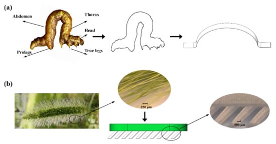
Figure 1.
Structure of a bio-inspired soft crawling robot (a) Inchworm-inspired leaf spring used in proposed soft crawling robot. (b) Spike-inspired robot feet [36].
The looping locomotion of the inchworm can contract their body to achieve relatively high speeds [37]. In our bio-mimic soft robot prototype, the TCP actuators will provide contraction and driving force, making the leaf springs deform like inchworms. Then, the ability to anchor to the ground is necessary to compel the robot to move through the ground. The leaf springs will deform horizontally with a constant body height and go through low passages. This working mechanism can also provide body stabilization and is good for carrying loads. Inspired by the special vibration behavior of setaria viridis spikes as shown in Figure 1b, the robot feet could be designed like the spike to generate an asymmetric force so that the robot can move in the desired direction [36]. This special behavior depends on the material’s elastic property and the structure of its spikes. The diameters and length of slant awns are 60–110 mm and 6–10 mm respectively, with an inclination angle of 40–60°. The forward direction is not equivalent to the backward direction because of the spike’s slant awns. The normal force FN between the awn and the sawtooth can be expressed as FN = G*A*α, where G is the awn’s shear modulus, A represents the contact area between the awn and the sawtooth, α is the awn’s deflection angle. The asymmetry friction force can be generated by the interaction between the awns and the ground. Therefore, a higher speed can be obtained by increasing the interacting area.
2.1. Soft Crawling Robot Design
3D model of the proposed soft crawling robot is shown in Figure 2c. The body and the robot feet are connected by the connection part. When subjected to voltage, the TCP actuators contract along the axial direction. Two TCP actuators allow the fast contraction of the robot body. The passive cooling speed in the cooling stage is improved by exposing the main part of the TCP actuators. Two leaf springs provide pre-tension for TCP actuators and a quick recovery for the robot body to its original state after the voltage is removed.
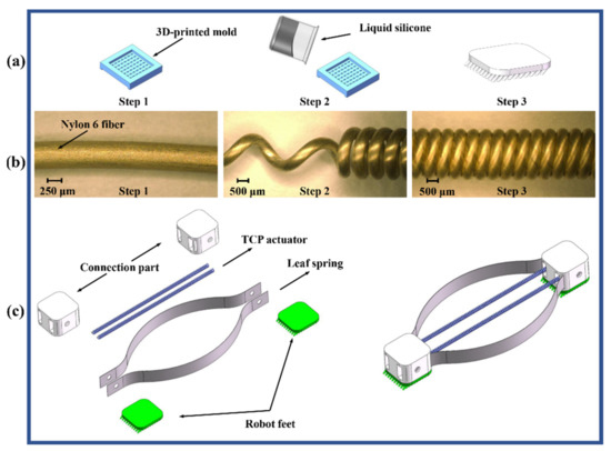
Figure 2.
Fabrication process of proposed soft crawling robot. (a) Fabrication process of the robot feet. (b) Fabrication process of the TCP actuators. (c) Fabrication process of proposed soft crawling robot.
2.2. Fabrication Process
The Shieldex conductive fiber (PN: 40024104600, Nylon 6, Shieldex®, Newark, NY, USA) was used to produce TCP actuators. This conductive fiber can be heated expediently without the help of other treatment because Joule heat would be generated when it is electrically activated. The fabrication process of the TCP actuators included two major steps:
- (a)
- Twist insertion and coiling. The process parameters are similar to our previous works [38,39]: A DC motor was attached to one end of the fiber sample to insert twist continuously by motor rotating. A hanging weight of 300 g was fixed to the other end. Then the twisted fibers were winded around a 1.38 mm diameter tribolet to form a helical structure.
- (b)
- Annealing and training. To relieve residual stress and prevent the untwist of samples, the TCP actuators were annealed at a temperature of 140 °C for 90 min in previous fabrication steps. Then, the TCP actuators were trained with the electric input (24 V, 10 cycles). During training, a hanging weight of 120 g was attached.
The crawling robot feet was made by silicon rubber (EcoflexTM 00-50, Smooth-On, Inc, Macungie, PA, USA), which is cured in a 3D-printed mold; such a process is shown in Figure 2a. Bubbles in liquid silicon was eliminated by vacuum. The shear modulus of Ecoflex-50 silicone can reach up to 82 KPa, which is helpful to enhance the asymmetry friction force of robot feet. The general micro-structure of robot feet was closed to the setaria viridis spike, while the size is larger. The inclination angle of robot feet is set as 45° according to the structure of spikes. The diameter of robot feet is set as small as possible to increase the interacting area and asymmetry friction force. The constrain is mainly from the manufacturing resolution of 3D printer. Connection parts was also 3D printed and the design of leaf springs (65 Mn steel alloy) is described in Section 3.2.
2.3. Experimental Conditions
The crawling robot was controlled by a microcontroller (AT89C51, Microchip Technology©, Chandler, AZ, USA). Upon actuation, a laser displacement meter (HG-C1100, Panasonic©, Osaka, Japan) and a micro force sensor (JLBS-M2, Jnsensor©, Bengbu, China) was used to measure the displacement and contraction force of the crawling robot respectively. The data were collected with a sampling frequency of 100 Hz through a DAQ modules (USB-4716-AE, Advantech©, Shanghai, China).
3. Model Formulation
3.1. Modelling TCP Actuator
Our previous work presented an elastic-rod-theory-based model to explain the quantitative relationship between stroke and fabrication load [38,39]. The elastic rod theory was used in the model to describe the relationship between twist-coiling process of TCP actuators and fabrication parameters (such as fabrication load). In the model, the tensile actuation can be accurately predicted when fabrication parameters are determined.
The stroke of TCP actuators can be described as:
where E denotes Young’s modulus, means the change of temperature, μ denotes Poisson’s ratio, αt is coefficient of thermal expansion, L represents unloaded coil length, F denotes fabrication load, N means number of coil turns, d is fiber diameter, and lc is fiber length in the coil.
The relationship between TCP temperature and actuation time could be derived from Newton’s law of cooling:
where represents the power of electrical supply, is heat capacity, represents the absolute thermal conductivity, means the temperature of TCP actuators, and denotes the ambient environment temperature.
The actuation process of our crawling robot mainly consists of two stages: heating-pull stage and cooling-push stage. In the heating-pull stage, the TCP actuators driven by the input electrical power will contract and pull the latter part of the robot. For the given input voltage, the input electrical power can be expressed as:
where denotes the input voltage, and represents the electrical resistance of actuators. If we combine Equations (2) and (3), we get
According to Equation (4), the temperature of TCP actuators in heating-pull stage can be expressed as:
Combine Equations (1) and (5), the relationship between tensile strain and actuation time will be:
The displacement–time curve of TCP under varied actuation voltage can be seen in Figure 3. In the cooling-push stage, the electrical power supply will be turned off, and the TCP will return to initial length to push the front section of the robot. Hence, in the cooling-push stage, the input electrical power will be:
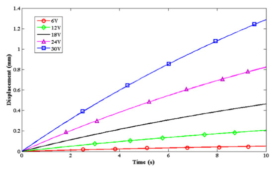
Figure 3.
Displacement–time curve of TCP under varied actuation voltage.
Combine Equations (2) and (7), the temperature of TCP actuators in the cooling-push stage can be expressed as:
3.2. Modelling Leaf Spring
Two elastic leaf springs are designed to produce pre-tensions of the TCP actuators, and also provide rapid, stable resilience for the TCP actuators to recover their initial states, as shown in Figure 4.
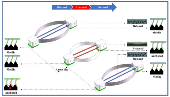
Figure 4.
The crawling mechanism of the proposed soft crawling robot.
Unlike commonly used linear springs, the readily bendable leaf springs radially expand when linearly compressed. The radial expansion improves the linear motion range, however, the large deformation is difficult to analyze and thus restricts the application of the leaf spring. According to our prior works [35,40], the integrated leaf springs can be approximated by a number of serial-connected small segments. Then, a 6-DOF linkage, composed of rigid bodies and elastic joints, can be constructed to approximate each small segment, based on the principal axes decomposition of structural compliance matrix [41]. Thereafter, the force-deflection behavior can be analysed based on the kinetostatics of the equivalent linkages. Using the POE formula for kinematic modelling [42], the configuration of the tip frame of the constructed mechanism glt, as well as the balance of the elastic deformation can be represented as
where represents the joint variables of the approximated spring. are the joint twists. is the spring’s initial pose in the local frame. 2n denotes the number of the joints. corresponds to the overall joint stiffness matrix, where and are the compliance for bending and torsion, respectively. E, G, δ, Ixx, and Izz are the elastic modulus, the shear modulus, the length of the small segment, and the moments of inertia in the bending and the torsion direction. Jθ is the Jacobian matrix. F represents the external wrench applied to the tip of the leaf spring.
Later, an optimization model to accomplish the force-deflection analysis can be expressed as
where relate to the variables of the optimization problem. denotes the target pose for the tip-frame of each leaf spring.
Thus, the gradient of the objective function can be written as
where is a configuration-dependent stiffness item.
Thereafter, the update theme for the variables in this equilibrium problem can be expressed as
which should be iteratively repeated until c approaches zero and the variables converge stably. Consequently, the force generated under the equilibrium configuration and the displacements of all the approximated joints can be simultaneously obtained, in terms of the resultant F and θ. Hence, the radial expansion and the resilient force of the leaf spring during the linear compression can be evaluated. Figure 5 illustrates the deformation statuses, as well as the generated force of a single leaf spring under different compression levels. With these predictable parameters, the TCP actuator, the leaf spring, can be designed in an appropriate manner to ensure the crawling process.
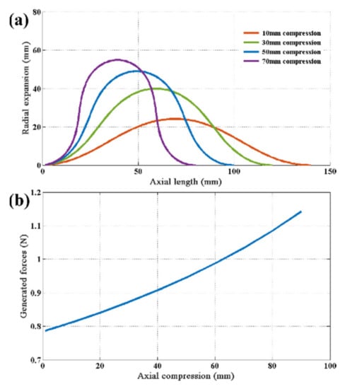
Figure 5.
Predicted deformation and force of a single leaf spring. (a) Deformation statuses under four compression levels. (b) Force-deformation curve during axial compression.
3.3. System-Level Model of the Crawling Robot
The model of TCP actuators and leaf springs in Section 3.1 and Section 3.2 can be incorporated into a system level model for designing and optimizing soft robotics utilizing TCP actuators. The total force of the crawling robot can be represented as
where represents the contraction force of TCP muscles, denotes the recovery force of the leaf spring and can be obtained in Equation (12), f is the friction force.
The contraction force of TCP muscles can be represented as [39]:
where d denotes fiber diameter, is Poisson’s ratio, D represents coil diameter of TCP, N means the number of coil turns, ∆L presents the change of coil length, T means the TCP temperature.
The material of the robot feet is silicone (friction coefficient: . For constant mass, the friction force can be represented as:
where Gg denotes gravitational force and means the friction coefficient.
The robot step S can be calculated as:
where represents the length change of TCP actuators defined in Equation (1) and is the probability of slippage.
According to ref [43], the probability of slippage can be defined as:
where erf() denotes the error function, is the contraction force of the robot, and Fs represents the static friction between the robot and the ground.
The contraction force of TCP muscles should be larger for quick pulling of the crawling robot in the actuation stage. The leaf spring provides a recovery force to return to the original state of robot body in the recovery period. The leaf spring can also offer pre-tension of TCP muscles in the original state for their free contraction. In the actuation stage, the total force of the crawling robot has to stay above zero to keep the robot crawl. Figure 6 illustrates the total force of the crawling robot and three separate components. The total force can be designed by adjusting the contraction force of TCP muscles and the recovery force of the leaf spring . The total force of the crawling robot is always larger than zero, as shown in Figure 6. Thus, when the slip of the robot feet is neglected, the displacement of the crawling robot can be approximately calculated by Equation (6).
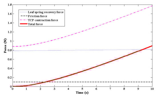
Figure 6.
Predicted force of the crawling robot.
To summarize, performance prediction of the robot can be accomplished as follows: by nailing fiber type, TCP diameter and processing parameters, the force and stroke are fixed (through Equations (1) and (14)). Thus, for the chosen TCP fibers, by only adjusting the input voltage and its applying time, the speed can be easily calculated (Equations (1)–(8), (16) and (17)) and the load capacity can be estimated through Equations (13)–(15). Hereby, the overall performance of the TCP—leaf based soft crawling robot can be deducted from those basic parameters. Twisting those basic parameters will receive a different output.
4. Results
4.1. Model Validation
The crawling robot was placed on the table for model validation. The heating power was offered by a DC power supply. When the electrical power was applied, the measurement of the displacement and force were completed by a laser displacement meter and a micro force sensor, respectively.
Figure 7 shows the displacement and force comparison between the prediction results and the experimental data of the crawling robot. The calculated results fit the fact precisely. For the displacement-actuation time model, the small discrepancy mainly comes from the restoring force generated by the leaf springs. The maximum step and force are around 5 mm and 0.7 N respectively when TCP actuators is actuated at 24 V electrical power. According to Equations (6) and (13), the displacement and force of the crawling robot can be optimized for desired performance requirements by selecting the ideal design parameters of the leaf springs and TCP actuators. It shows that our model can accurately predict the movement of the robot, making it feasible to control the speed of the robot and design different modes of locomotion.
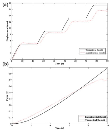
Figure 7.
Predicted and experimental results of the crawling robot. (a) Displacement-time curve. (b) Force-actuation time curve.
4.2. Multicycle Performance Optimization
The TCP actuator is thermally driven to produce tensile actuation. Generally, the period of heating is longer than that of cooling stage, which bring about an asymmetric locomotion of crawling robots [33,34]. It can present difficulties with robot control and stability of crawling. According to Equations (5) and (8), actuation temperature difference can be adjusted to obtain a near-symmetric actuation period. It is not difficult to achieve approximate symmetry by carefully programmed actuation cycles.
As shown in Equations (5) and (8), the real temperature of TCP actuators is determined by the actuation time and cooling time. Thus, they will influence the speed and displacement of the crawling robot according to Equation (1). To design multiple locomotion modes of the crawling robot, we set up experiments to test the characteristics of the robot under different temperature ranges with wide amplitude changes. The actuation period for different temperature ranges of TCP actuators is programed by TCP models in Section 3.1, as shown in Table 1 and Figure 8. Cooling speed is influenced by the temperature of the environment and TCP actuators. When the ambient temperature is constant, the cooling speed will increase with the temperature of TCP actuators. Thus, the TCP actuators have a faster cooling speed and a shorter actuation period in the high-temperature phase, which brings about a faster crawling speed.

Table 1.
Actuation period of TCP actuators under different working temperature ranges.
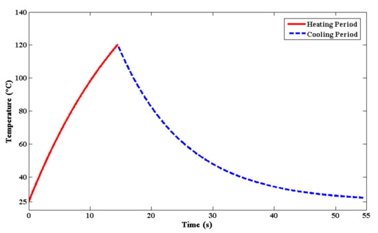
Figure 8.
Temperature of the TCP actuators during heating and cooling period. The red line shows the heating stage while the blue line means the cooling stage.
The crawling robot was actuated under temperature from 30 °C to 120 °C (as shown in Figure 9 and Video S1). Although the amplitude for different temperature ranges is constant (50 °C in this paper), the step displacement of the crawling robot become larger when it was actuated in a higher temperature range. The reason has been explained in previous work [31,32,39,44]: for Nylon fibers, the tie molecules tend to contract when they are expanded, while the crystalline bridges will show approximately equal resistance to keep the inter-crystal separation distance [31,44]. This distance is determined by the phase proportion and moduli of those two parts. When the temperature of TCP actuators become larger than the glass transition temperature (76 °C for Nylon material), the compression force becomes larger to shorten the inner separation distance because of the increasement of the amorphous tie molecules modulus, while the crystalline bridges show little variation in the modulus [31]. Thus, the contraction procedure of TCP actuators will be accelerated at a temperature above the glass transition temperature. For the same magnitude of the temperature rising, the high-temperature phase will bring about a larger contraction and robot step. A faster crawling speed of the proposed robot could be achieved by adjusting the actuation temperature difference.
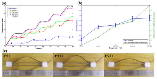
Figure 9.
Locomotion characteristics of proposed soft crawling robot. (a) Displacements of the crawling robot under varied temperature ranges. (b) Velocity and minimum traversable spacing at different temperature ranges. (c) Linear locomotion of the crawling robot at 70–120 °C without active cooling.
The recovery force offered by the leaf springs is also important when improving the speed of the crawling robot. When the voltage is applied, TCP actuators will contract to pull the rear part of the crawling robot and to compress the leaf springs. Meanwhile, the strain of TCP actuators increases with temperature before inter-coil contact, which brings about a greater compression of leaf springs [31]. After the deformation of the leaf springs reaches its maximum, the electrical power will be turned off, then the leaf springs will recover to their initial state to push the front part of the crawling robot. Leaf springs can provide a larger and controllable recovery force to obtain a faster crawling speed. The deformation and force of the leaf springs is predictable, which is complex and hard for traditional silicone body and springs [33,45]. Furthermore, when using springs as a pre-tension supplier, the actuation strain will be limited because of inter-coil contact. The leaf springs can offer external stress to provide room for contraction during actuation.
The velocity of the crawling robot increases from 0.062 mm/s to 0.275 mm/s when the range of actuation temperature changes from 30–80 °C to 70–120 °C as shown in Figure 9b. The maximum velocity could be further improved by employing the electrical power of a higher voltage to shorten the heating time. However, high actuation temperature will also impact the capacity of crawling through a narrow space. TCP actuators will show more contraction in high temperature, and bring about larger deformation of the leaf springs. The minimum traversable spacing will change from 6 mm to 8 mm when the range of actuation temperature changes from 30–80 °C to 70–120 °C. There is a contradictory between crawling velocity and minimum traversable spacing. This means that the crawling velocity may be sacrificed when the robot travels through a narrow space.
4.3. Load Capacity Testing
The load capability tests of the robot were conducted to test the locomotion under different payloads, as shown in Figure 10.
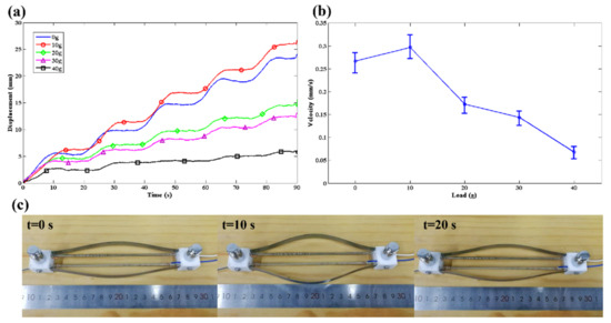
Figure 10.
Locomotion characteristics of proposed soft crawling robot under different payloads. (a) Displacements of the crawling robot under different payloads. (b) The velocity of the robot under different payloads. (c) Linear locomotion of the crawling robot at 60–110 °C with 40 g payload.
When the load increases from 0 g to 10 g, the speed of the robot shows a small increase. This may be attributed to the reduction of feet slips that is caused by the augmented pressure between robot feet and the ground. However, a heavier load will decrease the velocity of the robot due to an excessive friction force, which limits the contraction of the TCP actuators. The maximum load that can be carried by the robot is 40 g with a speed of 0.068 mm/s (as shown in Video S2). Considering that the total weight of the robot is 25 g with only 3 g weight of TCP actuators, the carry load reaches 1.6 times more than its body weight. It is sufficient to meet the requirements of an untethered soft robot to carry functional equipment.
5. Conclusions
In this paper, we presented a novel kind of inchworm-inspired soft crawling robot driven by TCP muscles with a quick recovery structure. The robot feet inspired by a spike can be easily manufactured, and anchor on the ground without obvious slippage to improve the locomotion efficiency. The model of the leaf springs and TCP actuators are proposed and validated through experiments. The performance of the crawling robot is improved by optimizing the design parameters of those models. Different locomotion modes with variable speed and minimum traversable spacing are obtained by these models. Experiment results showed that the soft crawling robot reaches a crawl speed of 0.275 mm/s when TCP is powered at 24 V. This robot is cheap and the manufacturing procedure of this robot is very easy. The loading capacity is encouraging compared with the current crawling robot driven by TCP actuators [33,34].
A comparison of the different soft crawling robots was shown in Table 2. The proposed crawling robot driven by TCP actuators showed a moderate load capacity compared with other robots. This low-cost robot can be easily manufactured and actuated without the requirements of rigid accessories (pumps) or conditions (high voltage), which means that it is suitable for rapid deployment to improve the efficiency of search and rescue tasks.
Table 2.
A comparison of different soft-crawling robots.
The model of TCP actuators and leaf springs are beneficial for locomotion mode design and speed improvement. A proper recovery force is very important for crawling robots to achieve a fast movement. Researchers prefer to use silicone bodies and springs to offer recovery force [34,45,54]. However, excessive recovery force will also weaken the actuation force of the robot during the actuation period, which impacts on the movement of the robot [45,54]. The deformation and recovery force of our leaf springs and TCP actuators are easier to control.
We have also shown that the locomotion efficiency of our crawling robot can be improved by properly setting the actuation period through our model. However, there is still some work to be done. The speed of the crawling robot is relative slow and is not fast enough to accomplish a mission that needs a fast reaction. The robot can only move in a straight line and it has a lack of steering capability. Improving these drawbacks requires fast thermal management in the system. For locomotion efficiency improvement, more TCP actuators can be employed to offer a larger contraction force. Besides, the actuation period could be shorted by decreasing the heating time (higher actuation voltage) or the cooling time (cool fluid or fan). Multiple joints will allow much more flexibility and will be the future approach to design various types of robots [17,55,56].
Supplementary Materials
The following supporting information can be downloaded at: https://www.mdpi.com/article/10.3390/machines10020142/s1, Video S1: Locomotion of crawling robot; Video S2: Load carrying experiment of crawling robot.
Author Contributions
Conceptualization, C.W. and W.Z.; data curation, Z.Z.; formal analysis, C.W.; funding acquisition, W.Z.; investigation, C.W.; methodology, C.W.; project administration, W.Z.; resources, W.Z.; software, C.W.; supervision, W.Z.; validation, C.W., Z.Z. and W.Z.; visualization, Z.Z.; writing—original draft, C.W.; writing—review and editing, C.W. All authors have read and agreed to the published version of the manuscript.
Funding
This research was supported in part by the financial support from the National Natural Science Foundation of China (NSCF) under Grant 51705313; and in part by the Natural Science Foundation of Shanghai under Grant 17ZR1414600.
Institutional Review Board Statement
Not applicable.
Informed Consent Statement
Not applicable.
Data Availability Statement
Not applicable.
Conflicts of Interest
The authors declare no conflict of interest.
References
- Hu, W.; Lum, G.Z.; Mastrangeli, M.; Sitti, M. Small-scale soft-bodied robot with multimodal locomotion. Nature 2018, 554, 81–85. [Google Scholar] [CrossRef] [PubMed]
- Wehner, M.; Truby, R.; Fitzgerald, D.J.; Mosadegh, B.; Whitesides, G.M.; Lewis, J.A.; Wood, R.J. An integrated design and fabrication strategy for entirely soft, autonomous robots. Nature 2016, 536, 451–455. [Google Scholar] [CrossRef] [PubMed]
- Thuruthel, T.G.; Shih, B.; Laschi, C.; Tolley, M.T. Soft robot perception using embedded soft sensors and recurrent neural networks. Sci. Robot. 2019, 4, eaav1488. [Google Scholar] [CrossRef] [PubMed]
- Shintake, J.; Cacucciolo, V.; Shea, H.; Floreano, D. Soft Biomimetic Fish Robot Made of Dielectric Elastomer Actuators. Soft Robot. 2018, 5, 466–474. [Google Scholar] [CrossRef] [PubMed] [Green Version]
- Lagomarsini, C.; Jean-Mistral, C.; Monfray, S.; Sylvestre, A. Optimization of an electret-based soft hybrid generator for human body applications. Smart Mater. Struct. 2019, 28, 104003. [Google Scholar] [CrossRef]
- Giorelli, M.; Renda, F.; Calisti, M.; Arienti, A.; Ferri, G.; Laschi, C. Learning the inverse kinetics of an octopus-like manipulator in three-dimensional space. Bioinspir. Biomim. 2015, 10, 035006. [Google Scholar] [CrossRef] [PubMed] [Green Version]
- Laschi, C.; Cianchetti, M.; Mazzolai, B.; Margheri, L.; Follador, M.; Dario, P. Soft Robot Arm Inspired by the Octopus. Adv. Robot. 2012, 26, 709–727. [Google Scholar] [CrossRef]
- Katzschmann, R.K.; DelPreto, J.; MacCurdy, R.; Rus, D. Exploration of underwater life with an acoustically controlled soft robotic fish. Sci. Robot. 2018, 3, eaar3449. [Google Scholar] [CrossRef] [Green Version]
- Cheng, T.; Li, G.; Liang, Y.; Zhang, M.; Liu, B.; Wong, T.-W.; Forman, J.; Chen, M.; Wang, G.; Tao, Y.; et al. Untethered soft robotic jellyfish. Smart Mater. Struct. 2019, 28, 015019. [Google Scholar] [CrossRef]
- Guan, Q.; Sun, J.; Liu, Y.; Wereley, N.M.; Leng, J. Novel Bending and Helical Extensile/Contractile Pneumatic Artificial Muscles Inspired by Elephant Trunk. Soft Robot. 2020, 7, 597–614. [Google Scholar] [CrossRef] [PubMed]
- Mitchell, S.K.; Wang, X.; Acome, E.; Martin, T.; Ly, K.; Kellaris, N.; Venkata, V.G.; Keplinger, C. An Easy-to-Implement Toolkit to Create Versatile and High-Performance HASEL Actuators for Untethered Soft Robots. Adv. Sci. 2019, 6, 1900178. [Google Scholar] [CrossRef] [Green Version]
- Joyee, E.B.; Pan, Y. A Fully Three-Dimensional Printed Inchworm-Inspired Soft Robot with Magnetic Actuation. Soft Robot. 2019, 6, 333–345. [Google Scholar] [CrossRef] [PubMed]
- Wang, W.; Lee, J.-Y.; Rodrigue, H.; Song, S.-H.; Chu, W.-S.; Ahn, S.-H. Locomotion of inchworm-inspired robot made of smart soft composite (SSC). Bioinspir. Biomim. 2014, 9, 046006. [Google Scholar] [CrossRef]
- Li, Z.; Huang, R.; Liu, Z. A Periodic Deformation Mechanism of a Soft Actuator for Crawling and Grasping. Adv. Mater. Technol. 2019, 4, 1900653. [Google Scholar] [CrossRef]
- de Rivaz, S.D.; Goldberg, B.; Doshi, N.; Jayaram, K.; Zhou, J.; Wood, R.J. Inverted and vertical climbing of a quadrupedal microrobot using electroadhesion. Sci. Robot. 2018, 3, eaau3038. [Google Scholar] [CrossRef] [PubMed] [Green Version]
- Robertson, M.A.; Efremov, F.; Paik, J. RoboScallop: A Bivalve Inspired Swimming Robot. IEEE Robot. Autom. Lett. 2019, 4, 2078–2085. [Google Scholar] [CrossRef]
- Umedachi, T.; Shimizu, M.; Kawahara, Y. Caterpillar-Inspired Crawling Robot Using Both Compression and Bending Deformations. IEEE Robot. Autom. Lett. 2019, 4, 670–676. [Google Scholar] [CrossRef]
- Jung, G.-P.; Casarez, C.S.; Lee, J.-E.; Baek, S.-M.; Yim, S.-J.; Chae, S.-H.; Fearing, R.S.; Cho, K.-J.; Fearing, R.S.; Chae, S.-H. JumpRoACH: A Trajectory-Adjustable Integrated Jumping–Crawling Robot. IEEE/ASME Trans. Mechatron. 2019, 24, 947–958. [Google Scholar] [CrossRef]
- Chen, S.; Cao, Y.; Sarparast, M.; Yuan, H.; Dong, L.; Tan, X.; Cao, C. Soft Crawling Robots: Design, Actuation, and Locomotion. Adv. Mater. Technol. 2020, 5, 1900837. [Google Scholar] [CrossRef]
- Lu, X.; Wang, K.; Hu, T. Development of an annelid-like peristaltic crawling soft robot using dielectric elastomer actuators. Bioinspir. Biomim. 2020, 15, 046012. [Google Scholar] [CrossRef]
- Shahinpoor, M.; Kim, K.J.; Shahinpoor, M.; Kim, K.J. Ionic polymer-metal composites: I. Fundamentals. Smart Mater. Struct. 2001, 10, 819. [Google Scholar] [CrossRef]
- Daily-Diamond, C.A.; Novelia, A.; O’Reilly, O.M. Dynamical analysis and development of a biologically inspired SMA caterpillar robot. Bioinspir. Biomim. 2017, 12, 056005. [Google Scholar] [CrossRef] [PubMed]
- Cao, J.; Qin, L.; Liu, J.; Ren, Q.; Foo, C.C.; Wang, H.; Lee, H.P.; Zhu, J. Untethered soft robot capable of stable locomotion using soft electrostatic actuators. Extreme Mech. Lett. 2018, 21, 9–16. [Google Scholar] [CrossRef]
- Ji, X.; Liu, X.; Cacucciolo, V.; Imboden, M.; Civet, Y.; El Haitami, A.; Cantin, S.; Perriard, Y.; Shea, H. An autonomous untethered fast soft robotic insect driven by low-voltage dielectric elastomer actuators. Sci. Robot. 2019, 4, eaaz6451. [Google Scholar] [CrossRef]
- Carrico, J.D.; Kim, K.J.; Leang, K.K. 3D-printed ionic polymer-metal composite soft crawling robot. In Proceedings of the 2017 IEEE International Conference on Robotics and Automation (ICRA), Singapore, 29 May–3 June 2017; pp. 4313–4320. [Google Scholar]
- Zhang, J.; Sheng, J.; O’Neill, C.T.; Walsh, C.J.; Wood, R.J.; Ryu, J.-H.; Desai, J.P.; Yip, M.C. Robotic Artificial Muscles: Current Progress and Future Perspectives. IEEE Trans. Robot. 2019, 35, 761–781. [Google Scholar] [CrossRef]
- Jani, J.M.; Leary, M.; Subic, A. Designing shape memory alloy linear actuators: A review. J. Intell. Mater. Syst. Struct. 2017, 28, 1699–1718. [Google Scholar] [CrossRef]
- Yuk, H.; Kim, D.; Lee, H.; Jo, S.; Shin, J.H. Shape memory alloy-based small crawling robots inspired by C. elegans. Bioinspir. Biomim. 2011, 6, 046002. [Google Scholar] [CrossRef]
- Chu, W.-S.; Lee, K.-T.; Song, S.-H.; Han, M.-W.; Lee, J.-Y.; Kim, H.-S.; Kim, M.-S.; Park, Y.-J.; Cho, K.-J.; Ahn, S.-H. Review of biomimetic underwater robots using smart actuators. Int. J. Precis. Eng. Manuf. 2012, 13, 1281–1292. [Google Scholar] [CrossRef]
- Mertmann, M.; Vergani, G. Design and application of shape memory actuators. Eur. Phys. J. Spéc. Top. 2008, 158, 221–230. [Google Scholar] [CrossRef]
- Haines, C.S.; Lima, M.D.; Li, N.; Spinks, G.M.; Foroughi, J.; Madden, J.D.W.; Kim, S.H.; Fang, S.; de Andrade, M.J.; Göktepe, F.; et al. Artificial Muscles from Fishing Line and Sewing Thread. Science 2014, 343, 868–872. [Google Scholar] [CrossRef]
- Haines, C.S.; Li, N.; Spinks, G.M.; Aliev, A.; Di, J.; Baughman, R.H. New twist on artificial muscles. Proc. Natl. Acad. Sci. USA 2016, 113, 11709–11716. [Google Scholar] [CrossRef] [PubMed] [Green Version]
- Yang, Y.; Tse, Y.A.; Zhang, Y.; Kan, Z.; Wang, M.Y. A Low-cost Inchworm-inspired Soft Robot Driven by Supercoiled Polymer Artificial Muscle. In Proceedings of the 2019 2nd IEEE International Conference on Soft Robotics (RoboSoft), Seoul, Korea, 14–18 April 2019; pp. 161–166. [Google Scholar]
- Tang, X.; Li, K.; Liu, Y.; Zhou, D.; Zhao, J. A soft crawling robot driven by single twisted and coiled actuator. Sens. Actuators A Phys. 2019, 291, 80–86. [Google Scholar] [CrossRef]
- Chen, G.; Zhang, Z.; Wang, H. A General Approach to the Large Deflection Problems of Spatial Flexible Rods Using Principal Axes Decomposition of Compliance Matrices. J. Mech. Robot. 2018, 10, 031012. [Google Scholar] [CrossRef]
- Bai, S.; Xu, Q.; Qin, Y. Vibration driven vehicle inspired from grass spike. Sci. Rep. 2013, 3, 1851. [Google Scholar] [CrossRef] [PubMed] [Green Version]
- Plaut, R.H. Mathematical model of inchworm locomotion. Int. J. Non-Linear Mech. 2015, 76, 56–63. [Google Scholar] [CrossRef]
- Wu, C.; Zheng, W. Position and Force Control of a Twisted and Coiled Polymeric Actuator. IEEE Access 2020, 8, 137226–137234. [Google Scholar] [CrossRef]
- Wu, C.; Zheng, W. A Modeling of Twisted and Coiled Polymer Artificial Muscles Based on Elastic Rod Theory. Actuators 2020, 9, 25. [Google Scholar] [CrossRef] [Green Version]
- Chen, G.; Zhang, Z.; Kong, L.; Wang, H. Analysis and Validation of a Flexible Planar Two Degrees-of-Freedom Parallel Manipulator With Structural Passive Compliance. J. Mech. Robot. 2020, 12, 011011. [Google Scholar] [CrossRef]
- Chen, G.; Wang, H.; Lin, Z.; Lai, X. The Principal Axes Decomposition of Spatial Stiffness Matrices. IEEE Trans. Robot. 2015, 31, 191–207. [Google Scholar] [CrossRef]
- Chen, G.; Wang, H.; Lin, Z. Determination of the Identifiable Parameters in Robot Calibration Based on the POE Formula. IEEE Trans. Robot. 2014, 30, 1066–1077. [Google Scholar] [CrossRef]
- Won, S.; Kim, S.; Park, J.E.; Jeon, J.; Wie, J.J. On-demand orbital maneuver of multiple soft robots via hierarchical magnetomotility. Nat. Commun. 2019, 10, 1–8. [Google Scholar] [CrossRef] [Green Version]
- Choy, C.L.; Chen, F.C.; Young, K. Negative thermal expansion in oriented crystalline polymers. J. Polym. Sci. Polym. Phys. Ed. 1981, 19, 335–352. [Google Scholar] [CrossRef]
- Lei, Q.; Qin, L.; Liang, X.; Huang, H.; Chui, C.K.; Yeow, R.C.H.; Zhu, J. A Versatile Soft Crawling Robot with Rapid Locomotion. Soft Robot. 2019, 6, 455–467. [Google Scholar]
- Kang, R.; Meng, F.; Chen, X.; Yu, Z.; Fan, X.; Ming, A.; Huang, Q. Structural Design and Crawling Pattern Generator of a Planar Quadruped Robot for High-Payload Locomotion. Sensors 2020, 20, 6543. [Google Scholar] [CrossRef] [PubMed]
- Su, Q.; Zhang, S.; Liu, Y.; Deng, J. A Quadruped Crawling Robot Operated by Elliptical Vibrations of Cantilever Legs. IEEE Trans. Ind. Electron. 2021, 68, 1466–1474. [Google Scholar] [CrossRef]
- Tolley, M.T.; Shepherd, R.; Mosadegh, B.; Galloway, K.C.; Wehner, M.; Karpelson, M.; Wood, R.J.; Whitesides, G.M. A Resilient, Untethered Soft Robot. Soft Robot. 2014, 1, 213–223. [Google Scholar] [CrossRef]
- Jiao, Z.; Ji, C.; Zou, J.; Yang, H.; Pan, M. Vacuum-Powered Soft Pneumatic Twisting Actuators to Empower New Capabilities for Soft Robots. Adv. Mater. Technol. 2019, 4, 1800429. [Google Scholar] [CrossRef] [Green Version]
- Chen, B.; Wang, N.; Chen, H.; Zhang, X. Study of an eccentric dielectric elastomer motor and its application for soft robots. Smart Mater. Struct. 2021, 30, 045014. [Google Scholar] [CrossRef]
- Arena, P.; Bonomo, C.; Fortuna, L.; Frasca, M.; Graziani, S. Design and Control of an IPMC Wormlike Robot. IEEE Trans. Syst. Man Cybern. Part B (Cybern.) 2006, 36, 1044–1052. [Google Scholar] [CrossRef]
- Hosokawa, D.; Ishikawa, T.; Morikawa, H.; Imai, Y.; Yamaguchi, T. Development of a biologically inspired locomotion system for a capsule endoscope. Int. J. Med. Robot. Comput. Assist. Surg. 2009, 5, 471–478. [Google Scholar] [CrossRef]
- Wang, W.; Rodrigue, H.; Lee, J.-Y.; Han, M.-W.; Ahn, S.-H. Smart Phone Robot Made of Smart Soft Composite (SSC). Compos. Res. 2015, 28, 52–57. [Google Scholar] [CrossRef]
- Liang, C.; Wang, Y.; Yao, T.; Zhu, B. A shape memory alloy–actuated soft crawling robot based on adaptive differential friction and enhanced antagonistic configuration. J. Intell. Mater. Syst. Struct. 2020, 31, 1920–1934. [Google Scholar] [CrossRef]
- Shi, Z.; Pan, J.; Tian, J.; Huang, H.; Jiang, Y.; Zeng, S. An Inchworm-inspired Crawling Robot. J. Bionic Eng. 2019, 16, 582–592. [Google Scholar] [CrossRef]
- Kandhari, A.; Wang, Y.; Chiel, H.; Daltorio, K.A. Turning in Worm-Like Robots: The Geometry of Slip Elimination Suggests Nonperiodic Waves. Soft Robot. 2019, 6, 560–577. [Google Scholar] [CrossRef] [PubMed]
Publisher’s Note: MDPI stays neutral with regard to jurisdictional claims in published maps and institutional affiliations. |
© 2022 by the authors. Licensee MDPI, Basel, Switzerland. This article is an open access article distributed under the terms and conditions of the Creative Commons Attribution (CC BY) license (https://creativecommons.org/licenses/by/4.0/).