Article

Developing Digital Observer of Angular Gaps in Rolling Stand Mechatronic System

by
Olga A. Gasiyarova
1,
Alexander S. Karandaev
1,
Ivan N. Erdakov
2,*,
Boris M. Loginov
1 and
Vadim R. Khramshin
3
1
Department of Mechatronics and Automation, South Ural State University, 454080 Chelyabinsk, Russia
2
Department of Metal Forming, South Ural State University, 454080 Chelyabinsk, Russia
3
Power Engineering and Automated Systems Institute, Nosov Magnitogorsk State Technical University, 455000 Magnitogorsk, Russia
*
Author to whom correspondence should be addressed.
Machines 2022, 10(2), 141; https://doi.org/10.3390/machines10020141
Submission received: 28 January 2022 / Revised: 10 February 2022 / Accepted: 13 February 2022 / Published: 16 February 2022
(This article belongs to the Special Issue Mechatronic System for Automatic Control 2022)

Abstract

:
Algorithms for monitoring the rolling mill mechatronic system state should be developed on the basis of modern digital technologies. Developing digital shadows (observers) of system state parameters in the periodic measurement mode is promising. This study relevance is defined by frequent emergency breakdowns of rolling stand mechanical transmissions. Most breakdowns are caused by worn end clutches (heads) of countershafts (spindles) transmitting rotation from the motor to the rolls. This is caused by elastic oscillations due to closing angular gaps when the metal enters the stand. The spindle joint angular gap increases over time with the mill operation. Therefore, it is an important diagnostic parameter that allows for an estimation of the transmission serviceability. In this regard, the problem of monitoring the angular gaps in the rolling stand mechatronic systems is relevant. The paper considers developing an observer of angular gaps in the spindle joints of the ‘electric drive-stand’ mechatronic system of the plate Mill 5000 of Magnitogorsk Iron and Steel Works PJSC (MMK PJSC). The monitored signal (angular gap) is calculated with the mathematical processing of the motor’s physical parameters (speed and electromagnetic torque), measured at a given frequency. The gap is determined indirectly by integrating the speed during its closing. To achieve this, the speed is controlled according to the triangular tachogram at no load. The stand’s electromechanical system modes have been studied using mathematical simulation. The observer’s practical use expediency has been reasoned. The structure of the observer-based angular gap monitoring information system is given. The system has been full-scale tested on Mill 5000, which has confirmed the developed algorithm efficiency. The study’s contribution is a justified and implemented concept of a relatively simple technical solution that can be commercially implemented without extra costs. The angular gap calculation algorithm does not involve complex mathematical techniques and can be implemented in industrial rolling mill controllers. Monitoring is automated without human involvement, which eliminates the human factor. The solution has a specific practical focus and is recommended for implementation at operating rolling mills.

1. Introduction

A new digital service—predictive maintenance (PdM)—is now gaining momentum in the industry. This technology is used to gather and analyze the equipment status data, forecast the time between overhauls, and prevent production failures [1,2]. Surely, such maintenance is promising for mechatronic systems of rolling production units operating under harsh conditions. Rolling mill breakdowns caused by equipment failures are costly for an enterprise, and eliminating their consequences increases dead expenses and the undersupply of products. According to [3], “the rolling mill operation is associated with significant wear of spindles, gearboxes, and bearings”. “Harsh operating conditions complicate implementing digital diagnostics” in them. According to [4], “angular and radial plays due to intense wear cause non-linear torsionals and significantly increase torque. This leads to equipment failures but can be used to diagnose wear during transients within the drive mechanism eigenfrequency range”.
Ref. [5] defines gear play as “the gap between adjacent moving parts”. It states that “every mechanical system where the driver (motor) is not directly connected to the follower (load) has a play”. This is exemplified by the rolling mill mechanical systems. A literature review shows that “controlling systems with plays have been studied since the 1940s, however, weirdly few innovations have been introduced since the first venture into the problem…” It is concluded that “play compensation to be studied much more in both synthesis and analysis”.
Thus, the problem of studying electromechanical systems with plays has a long history. However, we can argue that it has not been solved yet (and will scarcely ever have an unambiguous solution).
The wear of spindle heads causing them to break is among the most common rolling stand mechatronic system failures. The roll neck breakage is also a dangerous accident. Such damages are typical for horizontal stands of plate mills, including MMK PJSC’s Mill 5000 (hereinafter—Mill 5000) [6,7]. The authors of [3] note that “changes in process modes, processed material properties, and the drive speed complicate the monitoring of angular and radial gaps in spindle joints”. According to [8,9,10,11], globally digitalizing the metallurgical industry allows for the development of new approaches to forecasting and controlling the machine and mechanism states.
Practice shows that timely diagnosing pre-emergency situations may prevent the aforementioned (and many other) breakdowns. The spindle joint diagnostic monitoring complexity is associated with the impossibility of measuring wear directly during operation. Herewith, it is directly related to the angular gap. Regular monitoring at a predetermined interval will allow for an estimation of mechanical damage, fatigue failure, and other developing defects.
However, the angular gap cannot be directly measured during operation. The published ways of its calculation, based on the drive’s dynamic torque oscillography when the metal enters the stand (roll bite), have not brought about achieving the goal since isolating the torque component caused by the closing gap is difficult.
Angular gaps in the rolling mill torsion systems not only deteriorate their dynamic performance but also cause oscillations that adversely affect the rolling stability and the product quality [12,13,14,15,16,17,18,19]. Therefore, due to a combination of the aforementioned reasons, the problem of monitoring gaps in the main driveline (mainline) joints is relevant. Under modern conditions, it should be solved, considering the introduction of digital control algorithms and the equipment serviceability smart monitoring systems.
Experts from scientific institutions and industrial enterprises are developing technical aids for automated monitoring of the mechatronic system mechanical joint gaps [9,20,21,22]. Studies [3,8,23,24,25] are devoted to monitoring dynamic loads and forecasting the rolling mill electrical and mechanical equipment life. Ref. [24] proposes using angular and radial gaps to diagnose the drive mechanism wear during transients. Ref. [25] notes that, to close the gaps in the hot mill spindles, the drive is accelerated to the start of a transient caused by the roll bite. It also states that accelerating drives can be used to define the angular gaps. Periodic (sinusoidal, rectangular, triangular) signals sent to an idle motor change the gap used for diagnostics. This approach is the prototype of the solution proposed.
Some publications propose applying digital twins (DT) and shadows (observers) to monitor and assess the state of various-purpose mechatronic system transmissions [26,27]. Definitions and specifications of digital models, twins, and shadows are given in [28,29]. The practice of using observers to monitor the elastic torque in electromechanical system shafting is described in [30,31,32,33,34,35,36,37].
Ref. [38] provides an approach to the monitoring of offshore wind turbine transmission states. Such transmissions are similar to the rolling mill mainlines. The DT model provides an input for load observers designed and installed in specific transmission components. They serve to estimate the load and stress online at various points and to simulate the component degradation. The paper proves the proposed principle efficiency. The shortcoming is the need to store and process a large (as a rule, excess) volume of diagnostic data. Ref. [39] delves into developing and using DTs in the control and preventive maintenance of electrical machines. It stresses that significantly increased computing power, artificial intelligence, and IoT applications open up new research areas with new approaches and powerful tools for both laboratory and industrial conditions.
According to [40], DTs may gather data continuously or in intervals. Continuous monitoring may lead to excess data. Therefore, aging is stationary and does not depend on time for short intervals between measurements. Ref. [41] considers a digital device regularly measuring angular gaps in the driveline. For its operation, magnetic marks are applied to the spindle surface at a fixed pitch. Their location is read by two sensors and processed according to a given algorithm. The digital output signal generated by the device contains the angular gap data. In fact, it is one of the first observers of angular gaps in the spindle joints. Its shortcomings are the complicated use, associated with the need to read the magnetic mark data, and low accuracy. No information is provided on its commercial use.
The scientific publication analysis has confirmed the relevance of developing an observer of angular gaps in the spindle joints of the rolling stand mainlines. The observer should have the prospects of wide commercial use. The diagnostic algorithm should not require complex mathematical tools to process control signals. It should be implementable in the software of controllers installed on industrial units.
This publication discusses the results of developing an observer of angular gaps in the spindle joints of the Mill stand 5000 mainline. The observer operation is based on simulating (restoring) coordinates by processing the available parameters measured at a given frequency. Below, it is shown that the gap can be determined indirectly by the motor speed while simultaneously monitoring the electromagnetic torque in the slowing down mode.
The ultimate research objective is to develop an information-and-measuring system to calculate and visualize the spindle joint wear based on the angular gap monitoring. Measuring should be automated without human involvement.

2. Problem Formulation

2.1. Specifications of Dual-Mass Electromechanical Systems of the Mill Stand 5000

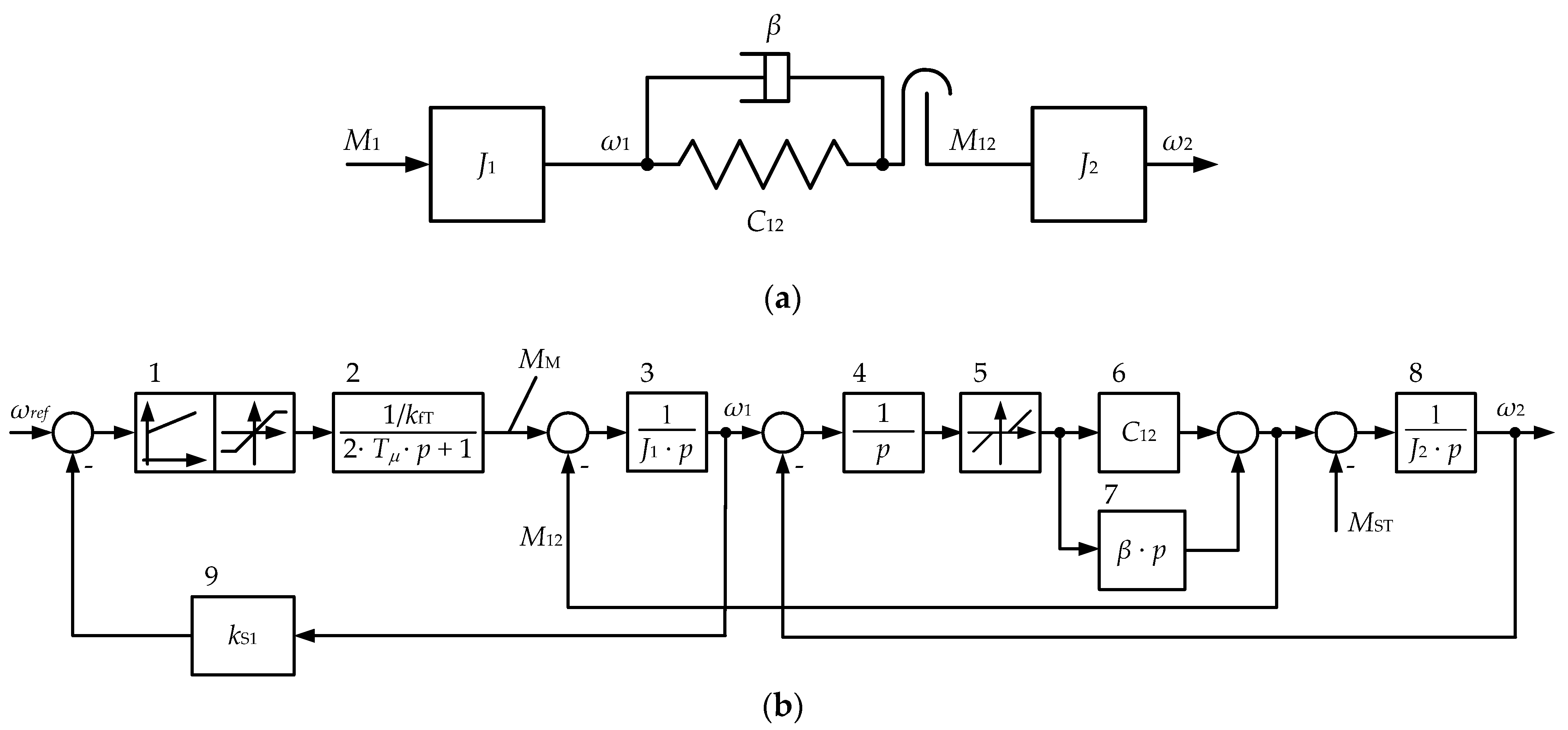
The upper and lower roll main drives (UMD and LMD) of the mill under study are independent and based on rpm-control synchronous motors. Their mechanical joints (Figure 1) have no devices with inertia (mass) commensurate with the motor’s one and the reduced inertia of the rolls. This allows for a description of the mainline as a dual-mass system with an elastic linkage and a gap in the mechanical joints (Figure 2a).
The system under research, electric drive and roll, can be represented as a closed dual-loop structure shown in Figure 2b. Blocks 3 and 5 to 7 are standard dual-mass system model blocks [42]. They define the quality of transients in the mechanical part, including the natural damping of oscillations (block 7). Block 5 simulates gaps in transmissions. The speed feedback is simulated by block 9 using the kS1 factor. Block 2 represents the closed torque control loop.
The model link parameters are given in Table 1 [43]. They have been determined by the electrical equipment data and oscillograms taken at the mill. The model assumes that the torque control loop is tuned to the modulus optimum. Therefore, to simplify the analysis, it has been represented by an aperiodic first-order link (block 2). The speed control loop is set to the symmetric optimum with a proportional-integral controller (block 1). Since the running drive’s torque is limited, it comprises a limiter block with variable limits. The table lacks an important parameter—the spindle gap. When simulating, the gap is adopted within 1 to 5° according to the operating practice.
The model adequacy to the object under study is not checked here since it has a known structure, and the simulated object parameters have been taken from the aforementioned paper [43]. The paper considers the simulation of transients during the biting with open and closed gaps in spindle joints. Comparing calculations with experimental oscillograms has proven their coincidence with satisfactory accuracy. Therefore, re-checking the adequacy is not required.

2.2. Spindle Design

Slipper-type spindles are installed in the reversing stand of Mill 5000 (Figure 3a). The roll is directly linked to the spindle using a head (see the photo—in the foreground) attached to the working shaft. A similar head is mounted on the motor side. Figure 3b shows the spindle-roll mechanical linkage design [23].
If the angular gap δ is open, then it closes during the biting with a mechanical impact and elastic oscillations in the spindle. In the newly installed mechanism, the joint gap is 1–2°. It is required to join two rotating parts—the spindle itself and the roll (or countershaft, Figure 1) and to facilitate free vertical travel of the rolls. The gap depends on the wear of the joining elements prone to fatigue failure. Most often, they break from the stand side. This is caused by the high roll rotation inertia, elastic impacts at the roll bite, the impact of the coolant, etc.
The complex design, impact loads, and harsh operating modes determine the relevance of developing measures to prevent the breakage of spindle joints. The least costly and yet most effective way to solve this problem is to promptly monitor their condition and, primarily, the angular gaps. At operating mills, they are manually measured by personnel during scheduled shutdowns. This is inefficient since it has no detailed regulations and requires time. In addition, measuring is performed under uneasy conditions; therefore, the human factor affects its reliability.

2.3. Experimental Justification of Preliminary Acceleration

The elastic torque on the spindle shaft is mainly caused by the high inertia of the dual-mass system formed by the roll mass on the one hand and the motor rotating part mass on the other hand. In the open-gap biting mode, the torque changes are oscillatory. According to [43], dynamic torque surges are determined by the elastic properties of the shaft. Thereafter, the oscillation amplitude is several times higher than the maximum dynamic torque that is directly caused by closing the gap.
As mentioned above, to preliminarily close the gap, it is recommended to perform biting in the roll acceleration mode [36,44,45]. Refs. [6,7] have proved that, in the gearless main lines, the properly chosen preliminary acceleration time ensures a guaranteed gap closure. In support of this, Figure 4 shows oscillograms of the motor torque Mmotor and speed n, as well as the torque Mshaft measured on the Mill stand 5000 upper roll spindle shaft [46]. The UMD and LMD spindle elastic torque Mshaft is measured by the overload monitoring system installed on the mill.
The oscillograms in Figure 4a have been obtained in the biting mode with fully open angular gaps. This is because the drive decelerates over the t1t2 time interval. The dependencies in Figure 4b have been obtained with closed gaps due to the drive acceleration over a similar time interval. The gap closes at a time instant t3, which is confirmed by small dynamic increments of the Mmotor torque. The oscillograms show that, in each case, the Mmotor и Mshaft torque transients are similar, and their amplitudes differ slightly. Table 2 provides oscillographic parameters at fixed points. The impact torque amplitude is characterized by the ktorque multiplicity defined as the ratio of the maximum Mmax to the steady-state Mst value. The dynamic deceleration is estimated by the control error (drawdown, Δ, %) defined as the percentage of the minimum speed nmin to its pre-biting value ncap.
The oscillogram and table data analysis allows us to draw the following conclusions:
-
For open-gap biting (Figure 4a), the impact torque amplitude exceeds the steady-state torque by 1.9 times (maximum Mmax = 3250 kN∙m, steady-state Mst = 1750 kN∙m);
-
Pre-closing the gap allows for the reduction of the drive speed dynamic deviation by 1.5 times, from 13.4% (Figure 4a) to 9.2% (Figure 4b);
-
The dynamic torque multiplicity ktorque decreases by 1.2 times, from 1.9 (Figure 4a) to 1.6 (Figure 4b).
This confirms that biting at open-gap deceleration significantly increases the dynamic torque, which can be reduced by generating tachograms with the drive pre-acceleration. In addition, the oscillograms provided confirm the oscillatory properties of spindle torques. Elastic oscillations are superimposed on the impactive gap closing while increasing the torque amplitude.
The problem of limiting the dynamic torque confirms the relevance of developing an observer of angular gaps in spindle joints. Since the fatigue failure of joints is of a long-term nature, online gap monitoring is not required. It is expedient to develop an automated gap calculation algorithm and include it in the stand calibration (adjustment) program run after each replacement of working rolls. As a rule, they are replaced once a day. This provides the required accuracy, and the obtained data volume is sufficient to diagnose the defect development intensity.

3. Materials and Methods

3.1. The Angular Gap Indirect Determination Procedure

An algorithm for monitoring spindle joint wear is proposed, involving the following actions:
-
Indirect angular gap definition by integrating the speed over the open-gap interval;
-
Fixing the change in the rotation direction (acceleration sign) and active gap closing instant with no metal in the rolls to estimate the interval boundaries.
The algorithm is explained by closing-gap speed and torque oscillograms shown in Figure 5. They have been obtained by reversing the upper roll drive with uniform deceleration and acceleration (for a triangular tachogram).
At the t1 time instant, when the motor torque sign changes, the transmission gap opens. By the t2 time instant, the gap closes, which confirms the further increase in the motor torque from 300 to 800 kN∙m. Assuming that the open-gap spindle speed is constant (changes according to curve 3), the angle can be calculated by the equation:
δ = 1 2 Δ n Δ t 0.1047 ,
where 0.1047 is the [rpm] to [rad/s] conversion factor.
In this case, Δn = 4 rpm, time interval Δt = 0.18 s, and, accordingly, angular gap δ = 0.038 rad or approximately 2.2°. According to this dependence, integration is replaced by the multiplication of speed and time increments. This simplification is justified since the speed (curve 2) changes linearly.
The linear change in speed is ensured with virtually no error when it is set as so (curve 1) in drives with PI speed controllers. This is because, in closed doubly integrating systems, the dynamic error of the command-based parameter control is zero. Therefore, the error in the angular gap calculation according to Equation (1) will also tend to zero. For the cases with non-linear changes in speed, the product of the speed and time increments should be replaced by the speed integral over time. This is noted in the algorithm description.

3.2. Developing an Observer

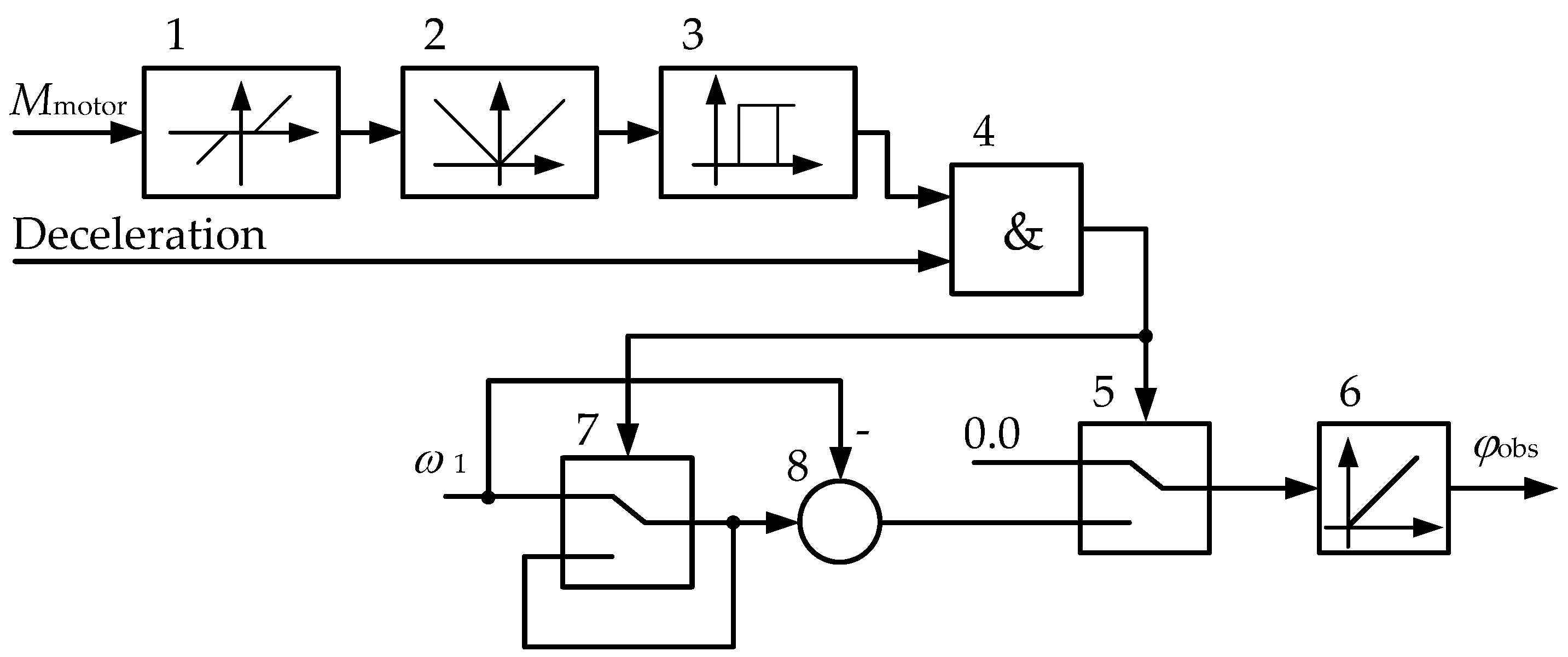
Figure 6 shows the block diagram of the developed observer. The input signals are the angular velocity ω1 and the motor torque Mmotor (with no load, this is the shaft torque). It is fed from the static torque sensor output included in the drive control algorithm. High torque calculation accuracy is not required since this signal serves to only fix the gap closing instant (t2 in Figure 5). Along with these parameters, the ‘deceleration’ logic signal is set. It determines the speed integration start instant by monitoring the acceleration (motor torque) sign. This signal should be generated at the t1 instant.
Blocks 1, 2, and 3 are used to determine the integration interval when the motor load torque is equal to the idling torque. The dead zone block 1 is required to compensate for the static torque definition error when the gap opens. The dead zone is assumed to make 1% of the rated torque. Block 2 is designed to calculate the torque module, and the relay block 3 generates a logical zero at the output if the input signal is not zero. The relay characteristic serves to improve noise immunity. The logic block 4 output closes the switch (block 5) at the integrator (block 6) input.
The blocks’ connection facilitates the resolution of the angular velocity signal integration provided two conditions are met simultaneously: the static load torque is equal to the idling torque (open gap), and the drive braking has started. After gap closure, the load torque increases, and the relay block 3 output signal comes to logical zero. As a result, switch 5 opens, the integration stops, and the block 6 output signal comes numerically to the angular gap value in the transmission.
For a triangular tachogram, when taking up the gap over the Δt interval, the drive speed (oscillogram 2 in Figure 5) changes linearly. Therefore, integration can be replaced by an approximate calculation with the formula:
φ obs = ε Δ t 2 = α R W Δ t 2 ,
where φobs is the angular gap calculated by the observer; ε is the angular acceleration (modulo) during the drive braking; α is the linear acceleration; RW is the roll radius.
The gap taking-up time is determined by the block 4 logical 1 output signal duration.
The observer scheme shown in Figure 6 is an open-circuited structure. It is an element of a diagnostic system not affecting the processes occurring in the electromechanical system studied. Therefore, checking the observer stability (convergence) is not required.
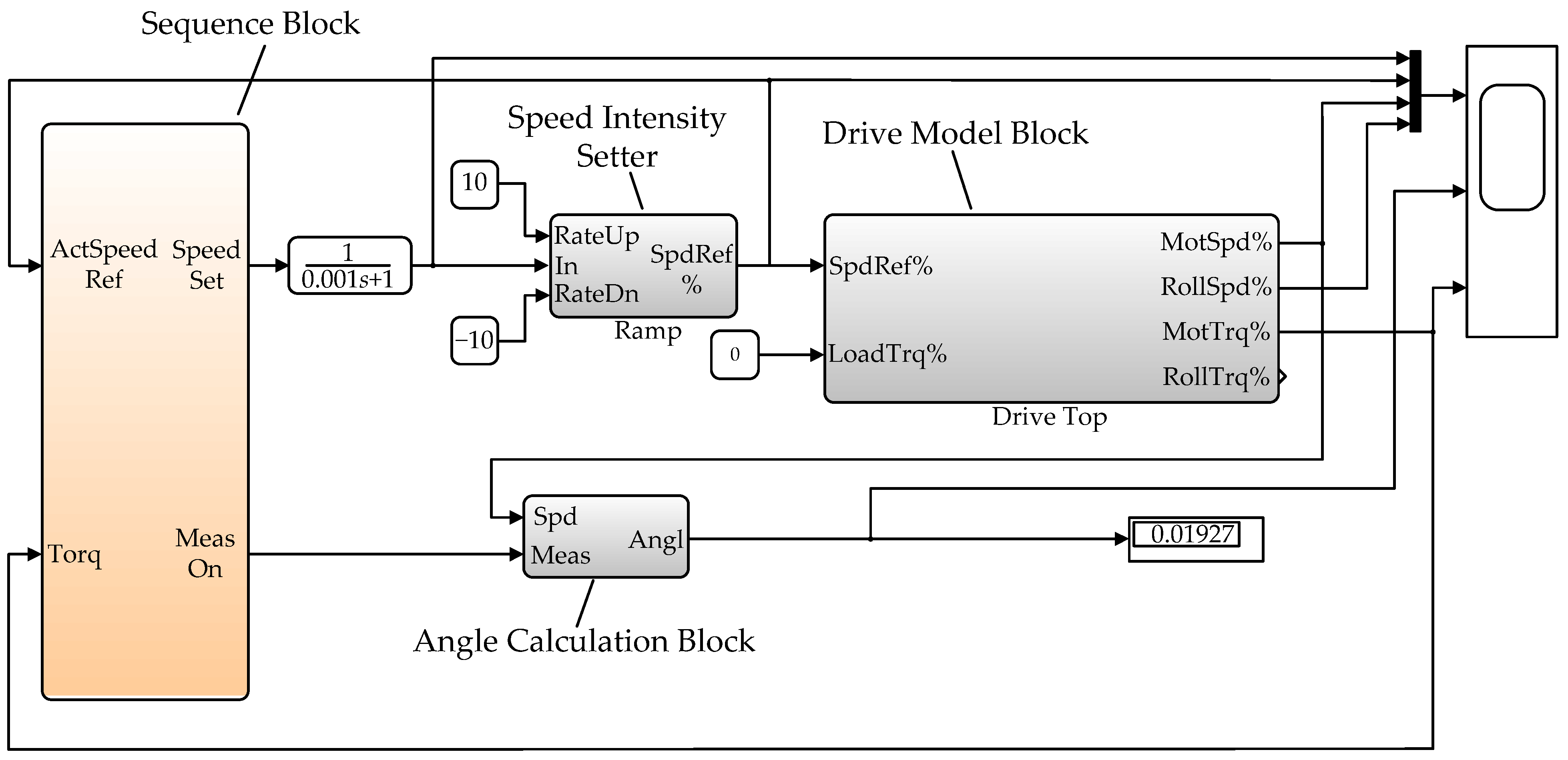
Figure 7 shows a diagram for a model simulating the angular gap measuring technique under consideration. It is implemented in the Simulink software using the Simscape package domains. This model is a simulator designed to configure an observer. An approach based on building virtual models of an object with a subsequent transfer of the debugged algorithm in the controller software is used to design mechatronic complexes of industrial units. This principle is also applied in virtual commissioning [47,48,49,50], diagnosing, and forecasting the technical condition of equipment [51].
The model comprises a test signal (sequence) generation block, an angular gap calculation block, and a speed intensity setter, controlled by the sequence block commands. It also includes a dual-mass model of the drive under study, the diagram of which is shown in Figure 2b. The sequence block comprises acceleration, deceleration, and measurement steps. The angular gap calculation block (Figure 6) fixes the current speed when the acceleration sign changes and integrates the difference between the fixed and actual motor speeds. Integration is performed until a short-term increase in the motor torque caused by closing the angular gap (in Figure 4 and Figure 5, these are t3 and t2 time instants, respectively). The block output is the measured angle.
Obviously, simulation studies should come before full-scale testing the technique developed. Since the speed and torque transient analysis does not require analyzing the drive’s ‘internal’ parameters (current, voltage, magnetic flux, etc.), a simplified simulation model of a dual-mass system is used, shown in Figure 2b.

3.3. Simulation and Experimental Studies

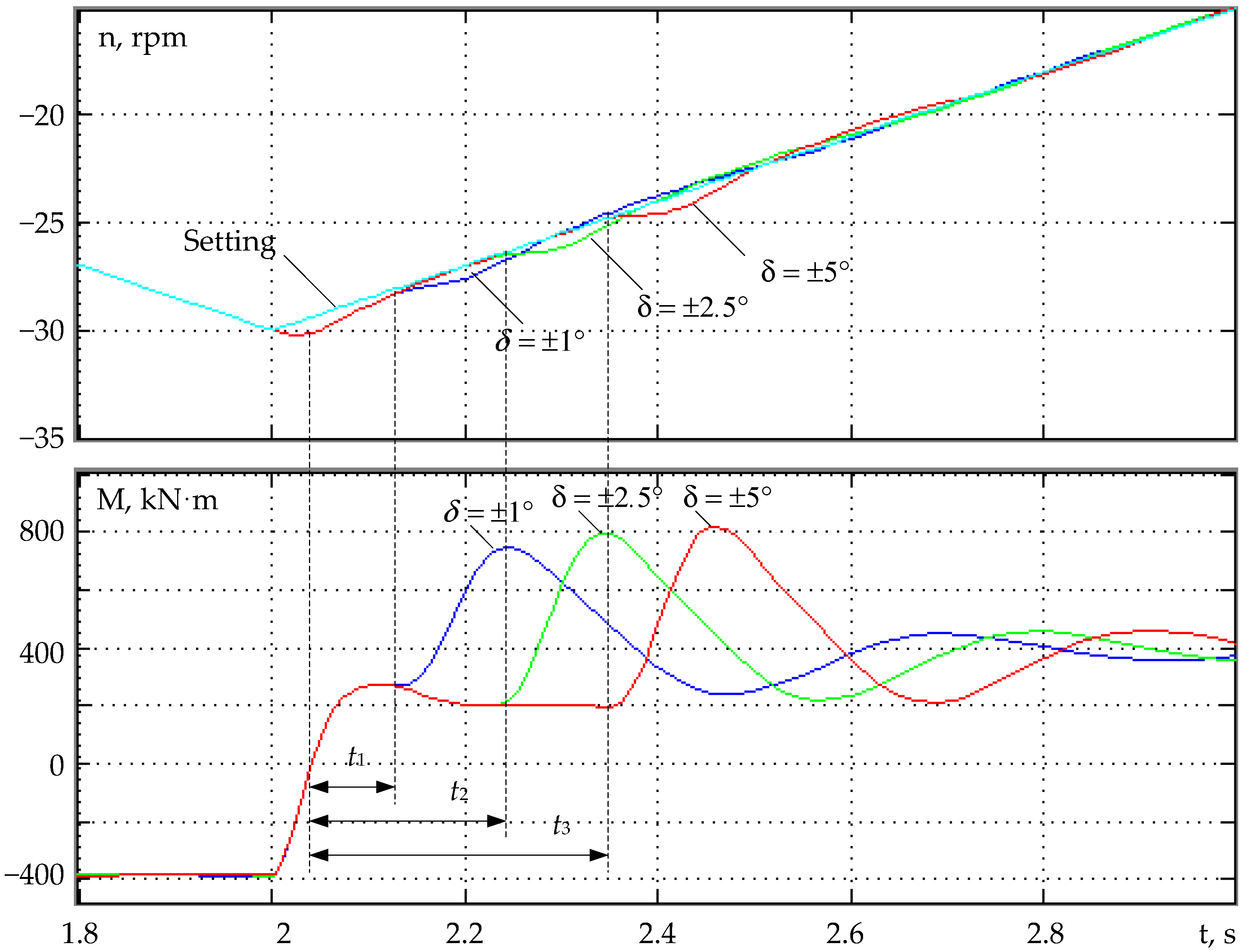
To verify the proposed algorithm’s reliability, experiments have been performed on the Mill 5000 with the load-free roll acceleration and deceleration. Positive and negative acceleration was ±0.523 rad/s2. Figure 5 shows the drive speed and torque change oscillograms. A similar mode was calculated for different transmission gap values using the model; the results are shown in Figure 8. Comparison of oscillograms and simulation results confirms their identity. The torque extremum instant depends on the gap size. In Figure 5, it is 0.2 s, and in Figure 8, amplitudes are achieved at the t1 = 0.11 s, t2 = 0.2 s, and t3 = 0.32 s instants with gaps ±1°, ±2.5°, and ±5°, respectively.
The analysis confirms that the transmission gap can be indirectly determined by the t1, t2, and t3 instants fixed by the static torque sensor signals.
The observer developed facilitates an indirect determination (restoration) of the angle δ by the gap closing time. This dependence cannot be determined analytically. Therefore, the simplest solution is to connect the observer at each measurement. In this case, the observer will be the object’s digital shadow. It will restore the monitored parameter by the measured drive coordinates. This allows for the recommendation of the observer developed for the implementation at operating rolling mills.
In addition, the calculated dependences provided allow us to conclude that the torque amplitude weakly depends on the gap. The studies in [43] have shown that the shaft elastic properties characterized by the stand stiffness modulus C12 and the damping ratio β (see Figure 2) affect the amplitude to a greater extent. In [44,52], to limit the dynamic torque, along with preliminary acceleration, short-term intensive drive braking immediately after the biting has been proposed. The negative dynamic torque arising in this case compensates (fully or partially) for the conditionally positive elastic torque on the spindle.
Experimental studies performed on the mill have shown that the angular gaps in the upper and lower roll spindle joints are commonly different. This is mainly caused by different wear of the spindle heads during operation. The difference in gaps is due to different roll loads, operating conditions, etc.
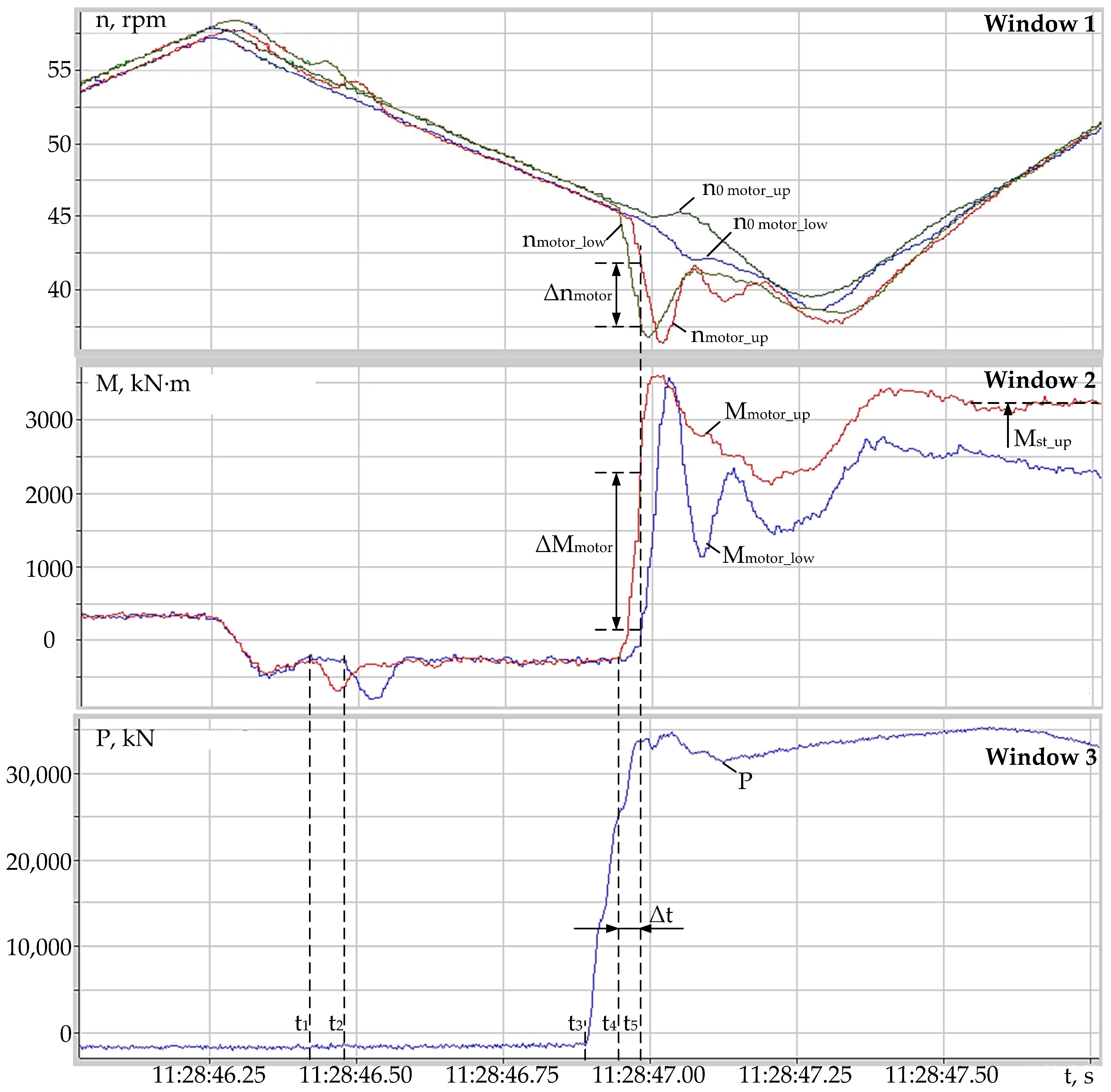
In support of the aforementioned, Figure 9 shows the motor speed (window 1) and torque (window 2) oscillograms under the impact load with the force P given in window 3. Biting occurs during the open-gap drives braking. As for Figure 4, this is confirmed by short-term changes in the Mmotor_up and Mmotor_low torques at t1 and t2 instants. In this case, the LMD spindle gap opens earlier; therefore, its value is less than that of the UMD spindle gap.
After gap closure, torques increase at t4 and t5 instants, and the difference Δt is ~0.25 s. This causes a difference of 10.2% in the motor speeds Δn (the LMD and UMD speeds are ~37.5 and 41.8 rpm, respectively) by the t5 instant. Therefore, over the t4t5 time interval, an additional torque component will appear, accelerating the LMD motor and decelerating the UMD one. At the ΔMmotor instant, the torque difference is 66% of the steady-state value Mst_upMmotor = 2180 kN∙m, Mst_up = 3300 kN∙m). The speed difference may probably lead to slippage of the ‘faster’ roll relative to the strip. There is a risk of damaging the roll surface, which is equated to an emergency. This issue requires a more detailed study using mathematical simulation.
Mathematical models of the UMD and LMD mechatronic systems, developed considering their linkage through metal, have been described in [53,54,55]. Dynamic drive modes at the roll slippage have been studied in [56,57,58]. For the purpose of this undesirable mode avoiding, it is relevant to study the issues of robust drive control, which guarantee that their mutual impact is reduced to minimum. A similar problem has been solved for blooming drives, and the results are given in [59,60]. For plate and wide-strip hot mills, such a study is of scientific and practical interest; however, it is an independent task due to its complexity.
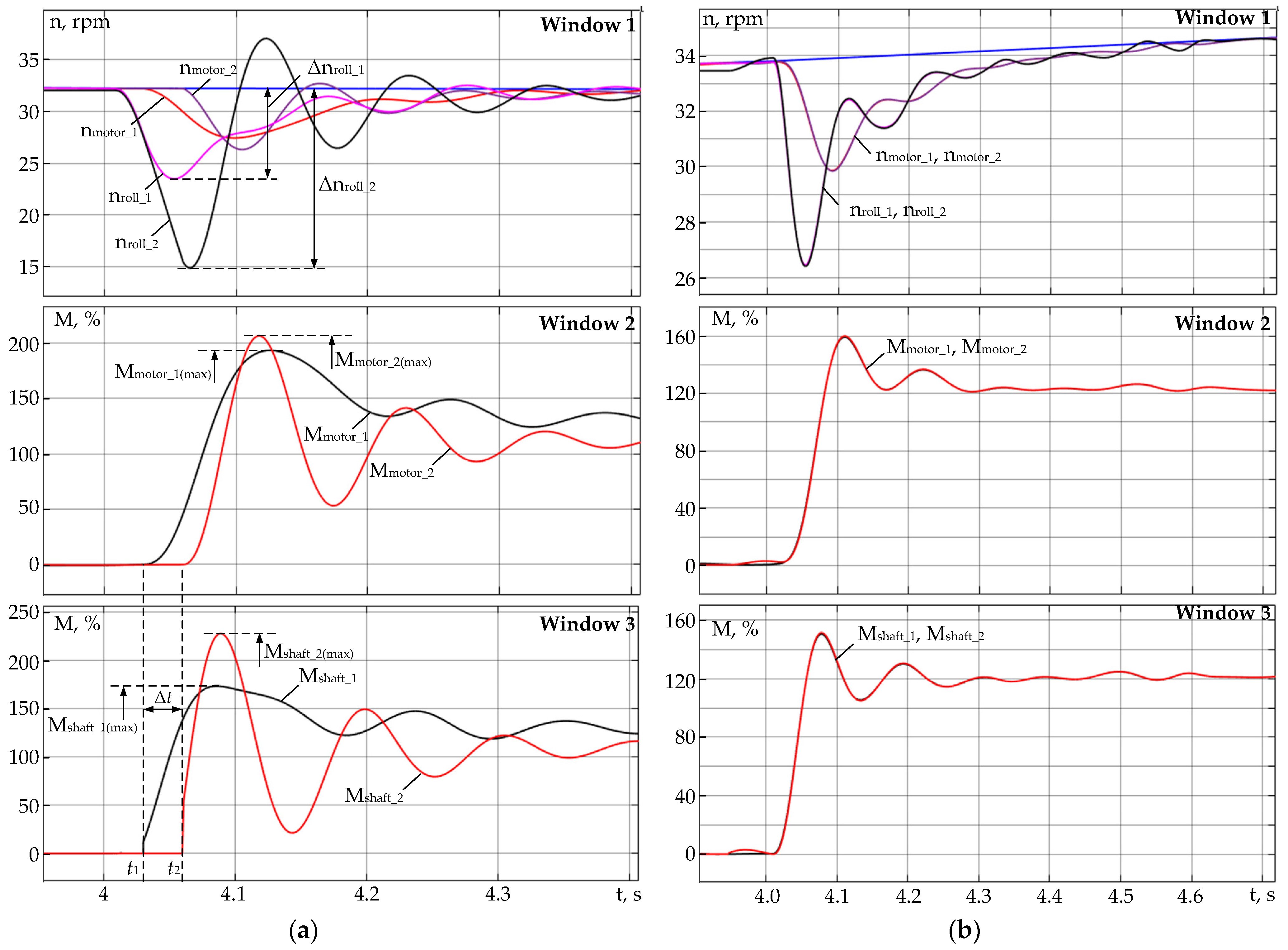
The UMD and LMD transient simulation results without considering the linkage through metal are given in Figure 10. Figure 10a shows the time dependences of speeds and torques with different angular gaps: the LMD (index 1 in Figure 10) and UMD (index 2 in Figure 10) spindle gaps are 0.5 and 3°, respectively. Figure 10b provides similar dependencies for fully closed gaps. Table 3 provides dynamic torque deviations for the cases shown in Figure 10a.
The result analysis allows us to draw the following conclusions:
  • The Mmotor_1 (max) and Mmotor_2 (max) motor torque amplitudes (window 2, Figure 10a) differ by 9.5%. The Mshaft_1 (max) and Mshaft_2 (max) spindle elastic torque amplitudes (window 3) differ by 27%. This indicates a significant impact of gaps on the transients of these parameters under the same biting conditions (for the upper and lower rolls, these conditions are the same);
  • The t1 and t2 upper and lower spindle gaps closing instants also differ. Under the same biting conditions, a spindle with a larger play is loaded later. With the specified gaps, the time difference Δt is 25 ms;
  • In the electromechanical system with a large angular gap, longer damping elastic torque oscillations with a larger amplitude occur. The dynamic deviations of the second mass (roll) speed Δnroll_2 exceed those of the first mass speed Δnroll_1;
  • In Figure 10b, curves of the UMD and LMD torque transients at closed gaps match. It can be argued that the system is linearized since the non-linearity introduced by the gaps disappears.
The analysis confirms the impact of the spindle angular gaps on the speed and elastic torque transients. With an increase in the gap, the torque transient parameters deteriorate: the oscillation amplitude increases, and the damping rate decreases. Therefore, biting should be performed under the condition of preliminarily closing the spindle gaps of both electromechanical systems. This requires calculating the acceleration necessary to the guaranteed closing of both gaps.

4. Implementation

The optimal drive acceleration is calculated using the oscillograms shown in Figure 5. According to Equation (1), the angular gap δ is proportional to the area of the triangle bounded by the 2 and 3 curve sections over the Δt time interval. The desired acceleration α Ref is related to the linear velocity vRef by the dependence:
v Ref = α Ref t .
Considering (2), the angular gap (in radians) is determined as follows:
δ = 1 2 R W α Ref Δ t 2 ,
where [RW] = m.
The Δt time required to close the gap δ is determined at each replacement according to the technique proposed. The acceleration required to close the gap is:
α Ref = δ 2 R W Δ t 2 .
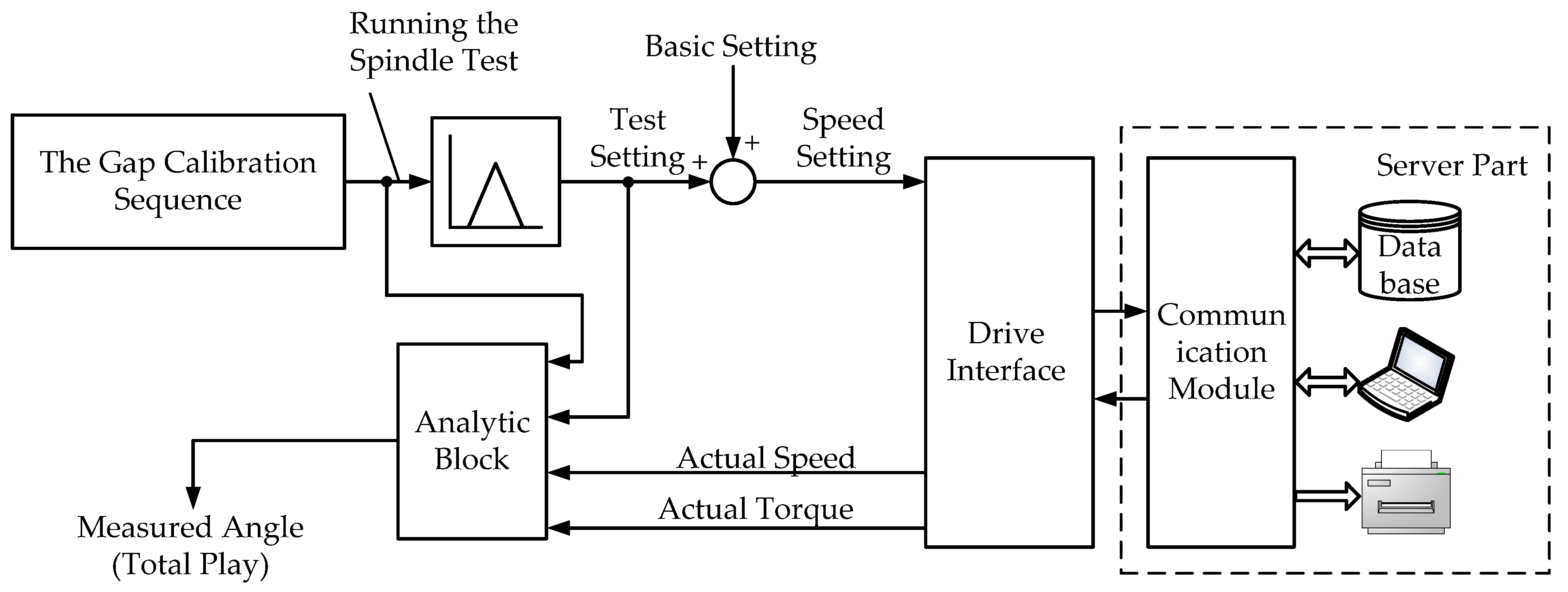
For the automated gathering, storage, and analysis of the periodic measurement results, the information system structure has been proposed, and is shown in Figure 11. The gap is calculated automatically before starting the mill after completing the stand calibration. To achieve this, a test effect on the drive is set. The analysis (angle calculation) block structure is shown in Figure 6.
The observer is configured once, and its software stipulates for the following actions:
  • Programming and adapting the gap measurement algorithm using a simulator (virtual model), the scheme of which is shown in Figure 7;
  • Transfer of the debugged program to the industrial controller software. These actions provide virtual commissioning, reducing the observer configuration time. Such an approach is expedient since the angular gap is difficult to measure and impossible to change under the operating mill conditions. The virtual input allows for any changes in the monitoring algorithm;
  • Experimental approval or correction of the calculated drive acceleration, ensuring guaranteed closing of the maximum gap;
  • Experimental setting of the dead zone in block 1, Figure 6, allowing for a reliable determination of the opening time instant;
  • Introducing the algorithms developed into the calibration program.
The full-fledged commercial system operation requires:
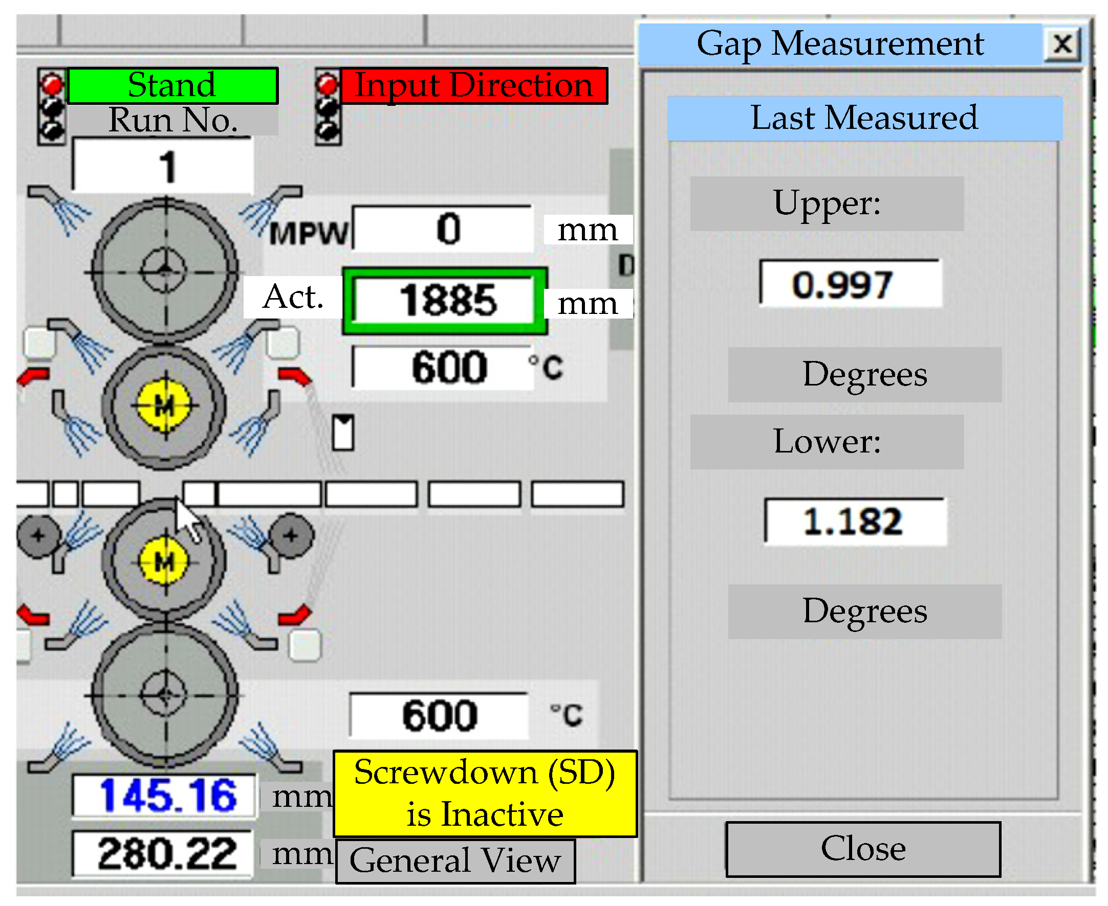
  • Visualizing the spindle joint serviceability data. A drop-down window is provided on the operator’s display to warn about developing an emergency. The view of such a window on the Mill 5000 stand control station display is given in Figure 12;
  • Building empirical dependences of the spindle joint wear on the angular gap. They should be obtained by statistically processing experimental data with a large volume of measurements. Dependencies will provide sufficient accuracy since the joint wear is of a long-term nature.
The roll diameter and wear and other external factors cannot affect the internal gap between the rectangular roll blade and the joint elements shown in Figure 3b. The main (and only) reason for increasing angular gaps is the wear of the spindle joint elements and the roll blade. Therefore, the gap value is a diagnostic feature that unambiguously and reliably characterizes the joint wear degree.
The dependences obtained will allow for not only a prompt assessment of the mechanical joint state but also a determination of the fault development rate. This facilitates forecasting the time to reach the limits set. Justifying the angular gap limits corresponding to the degraded and pre-emergency states is among the problems to be solved after the data accumulation.
3.
Developing tailored software to determine the wear dynamics and forecast the spindle joint state is expedient. They should provide a mathematical processing of diagnostic parameter trends. Building trends requires the accumulation of large data volumes. This predetermines the expediency of creating a customized database.
Authors should discuss the results and how they can be interpreted from the perspective of previous studies and of the working hypotheses. The findings and their implications should be discussed in the broadest context possible. Future research directions may also be highlighted.
More detailed information on the built system hardware and software can be the subject of a separate publication. The system operation data will be provided after debugging the algorithms for gathering and processing diagnostic data in an industrial environment.

5. Conclusions

Experimental studies performed on the Mill 5000 have confirmed defects developing in the reversing stand spindle joints. Developing angular gaps negatively affects the spindle life. The experimental oscillogram analysis has shown that the total gaps in the upper and lower roll spindle joints differ. Along with the deteriorated dynamics during the biting, this may lead to roll slippage relative to the workpiece. This causes damage to the roll surface, necessitating its unscheduled replacement. The replacement of expensive equipment—spindles and rolls—increases dead expenses, the unit downtime, and, eventually, the undersupply of products. The rotating equipment breakdowns also pose a potential hazard to maintenance personnel.
The literature review confirmed the relevance of developing an observer of angular gaps in the rolling mill mainline spindle joints. The expediency of the regular automated measurement of angular gaps without human involvement has been justified. The literature provides no information on commercial developments to solve this problem.
A technique has been developed for indirectly determining spindle joint gaps for stands with independent roll drives. It comprises the following:
  • Setting the drive speed to provide the gap closing when the shaft rotates in one direction, and then opening and repeatedly closing when the shaft rotates in the opposite direction. To achieve this, the speed tachogram should have a triangular shape with equal deceleration and acceleration rates;
  • The motor electromagnetic torque monitoring to determine the gap closing and opening instants when testing the tachogram;
  • Recording the speed signal over the open-gap time interval. Calculating the angular gap as a speed integral over this interval. For the linear time dependence of speed ensured by the triangular tachogram, integration can be replaced by multiplying the speed and time increments.
An observer of the spindle joint angular gaps has been developed. It stipulates for the gap restoration (indirect determination) by continuously monitoring parameters: the motor speed and electromagnetic torque. Its benefits include easy configuring and the possibility of obtaining a monitored signal by a given command without human involvement.
Transients have been studied using simulation. To carry this out, a simulation model has been developed, implemented in the Simulink software using the Simscape package domains. The simulation results confirmed the relevance of closing the gaps before biting, regardless of their size. They also confirm the reliability of the proposed technique for monitoring the angular gaps and the feasibility of the commercial implementation of the observer developed.
The paper provides the experimental results for specific spindle speeds, workloads, and roll radii. These conditions have not been chosen specially and are typical for the Mill 5000. Similar results have been obtained when rolling various types of sheets. The rolling conditions do not affect the spindle joint gap, which is determined by the wear of the spindle joint elements and the roll blades. Therefore, the results obtained are reliable. This is confirmed by the results of long-term pilot tests of the algorithm implemented.
The eventual outcome is the spindle joint wear monitoring information system based on regular automated angular gap measurements. Implementing algorithms for automated angular gap monitoring will provide a diagnosis of the defect development intensity. This allows for the elimination of dangerous situations during routine maintenance without additional mill shutdowns.
The observer developed is designed to prevent the breakage of spindles and roll necks of MMK PJSC’s Mill 5000 reversing stand. Therefore, its implementation in other (plate, wide-strip, section) hot mills would be effective, the characteristic mode of which is the impact load during biting.
The implementation would ensure:
-
A reduction of the emergency mill downtime;
-
A reduction of the cost of eliminating the consequences of accidents, and replacing and restoring equipment;
-
An extension of the service life of electrical and mechanical equipment.
The long-term experimental studies of the implementation efficiency, as well as gathering and processing statistical data, are required. The results of such studies can be provided in further publications.

Author Contributions

Methodology, A.S.K.; ideas O.A.G.; software I.N.E.; validation V.R.K.; formal analysis B.M.L. All authors have read and agreed to the published version of the manuscript.

Funding

Research was funded by the Ministry of Science and Higher Education of the Russian Federation under a subsidy for a government-funded basic research project, Contract No. FENU-2020-0020 (2020071GZ).

Institutional Review Board Statement

Not applicable.

Informed Consent Statement

Not applicable.

Data Availability Statement

Not applicable.

Conflicts of Interest

The authors declare no conflict of interest.

References

  1. El-Thalji, I. Predictive maintenance (PdM) analysis matrix: A tool to determine technical specifications for PdM ready-equipment. IOP Conf. Ser. Mater. Sci. Eng. 2019, 700, 012033. [Google Scholar] [CrossRef]
  2. A Survey of Predictive Maintenance: Systems, Purposes and Approaches. Available online: https://www.researchgate.net/publication/337971929_A_Survey_of_Predictive_Maintenance_Systems_Purposes_and_Approaches (accessed on 25 January 2022).
  3. Krot, P.; Prykhodko, I.; Raznosilin, V.; Zimroz, R. Model Based Monitoring of Dynamic Loads and Remaining Useful Life Prediction in Rolling Mills and Heavy Machinery. In Advances in Asset Management and Condition Monitoring. Smart Innovation, Systems and Technologies; Ball, A., Gelman, L., Rao, B., Eds.; Springer: Cham, Switzerland, 2020; Volume 166, pp. 399–416. [Google Scholar] [CrossRef]
  4. Management Problems of Rolling Mills Equipment Technical Operation. Fundamental and Applied Problems of Ferrous Metallurgy. Available online: http://dspace.nbuv.gov.ua/bitstream/handle/123456789/21509/38-Krot.pdf?sequence=1 (accessed on 25 January 2022).
  5. Nordin, M.; Gutman, P.-O. Controlling mechanical systems with backlash—A survey. Automatica 2002, 38, 1633–1649. [Google Scholar] [CrossRef]
  6. Karandaev, A.S.; Gasiyarov, V.R.; Maklakova, E.A.; Loginov, B.M.; Khramshina, E.A. Method limiting dynamic loads of electromechanical systems of plate mill stand. In Proceedings of the IEEE Conference of Russian Young Researchers in Electrical and Electronic Engineering (EIConRus), Moscow and St. Petersburg, Russia, 29 January–1 February 2018; pp. 651–656. [Google Scholar] [CrossRef]
  7. Radionov, A.A.; Gasiyarov, V.R.; Karandaev, A.S.; Khramshin, V.R. Use of automated electric drives for limiting dynamic loads in shaft lines of roll mill stands. J. Eng. 2019, 2019, 3578–3581. [Google Scholar] [CrossRef]
  8. Ohlert, J.; Sprock, A.; Sudau, P. Digitalization in hot and cold rolling mills. Mat. Sci. Forum 2016, 854, 215–224. [Google Scholar] [CrossRef] [Green Version]
  9. Lei, Y.; Li, N.; Guo, L.; Li, N.; Yan, T.; Lin, J. Machinery health prognostics: A systematic review from data acquisition to RUL prediction. Mech. Syst. Signal Process. 2018, 104, 799–834. [Google Scholar] [CrossRef]
  10. Bachschmid, N.; Pennacchi, P.; Vania, A. Identification of multiple faults in rotor systems. J. Sound Vibr. 2003, 254, 327–366. [Google Scholar] [CrossRef] [Green Version]
  11. Tinga, T.; Loendersloot, R. Physical model-based prognostics and health monitoring to enable predictive maintenance. In Predictive Maintenance in Dynamic Systems: Advanced Methods, Decision Support Tools and Real-World Applications; Lughofer, E., Sayed-Mouchaweh, M., Eds.; Springer: Cham, Switzerland, 2019; pp. 313–353. [Google Scholar] [CrossRef]
  12. Mapelli, F.; Ruspini, E.; Sabbioni, E.; Tarsitano, D. A state observer for speed regulation in rolling mill drives. In Structural Dynamics, Volume 3. Conference Proceedings of the Society for Experimental Mechanics Series; Proulx, T., Ed.; Springer: New York, NY, USA, 2011; pp. 1193–1205. [Google Scholar] [CrossRef]
  13. Zhang, R.; Chen, Z.; Yang, Y.; Tong, C. Torsional vibration suppression control in the main drive system of rolling mill by state feedback speed controller based on extended state observer. In Proceedings of the IEEE International Conference on Control and Automation, Guangzhou, China, 30 May–1 June 2007; p. 4376745. [Google Scholar] [CrossRef]
  14. Xu, Y.; Chao-nan, T. Nonlinear Modeling and Global Sliding Mode Control of Main Drive System Torsional Vibration in Cold Rollling Mill. In Proceedings of the V International Conference on Intelligent Computation Technology and Automation, Zhangjiajie, China, 12–14 January 2012. [Google Scholar] [CrossRef]
  15. Fan, X.; Zang, Y.; Jin, K. Rolling process and its influence analysis on hot continuous rolling mill vibration. Appl. Phys. A 2016, 122, 1008. [Google Scholar] [CrossRef]
  16. Qian, C.; Zhang, L.; Hua, C. Adaptive Torsional Vibration Control of the Nonlinear Rolling Mill Main Drive System with Performance Constraints and Sensor Errors. Int. J. Control Autom. Syst. 2021, 19, 1264–1272. [Google Scholar] [CrossRef]
  17. Peng, Y.; Cui, J.; Sun, J.; Zhang, M. Torsional Vibration for Rolling Mill with the Drive System Shaft Axis Deviations. Arab. J. Sci. Eng. 2021, 46, 12165–12177. [Google Scholar] [CrossRef]
  18. Peng, R.; Zhang, X.; Shi, P. Vertical–Horizontal Coupling Vibration of Hot Rolling Mill Rolls under Multi-Piecewise Nonlinear Constraints. Metals 2021, 11, 170. [Google Scholar] [CrossRef]
  19. Fan, X.B.; Zhao, B.; Jiang, Y.; Fan, B.X. Review on main drive torsional vibration and roller coupling vibration of rolling mill. Recent Pat. Eng. 2020, 14, 1872–2121. [Google Scholar] [CrossRef]
  20. Butler, D.H.E.; Churches, M.A.; Anbe, Y.; Naitoh, H. Compensation of a digitally controlled static power converter for the damping of rolling mill torsional vibration. IEEE Trans. Ind. Appl. 1992, 28, 427–433. [Google Scholar] [CrossRef]
  21. Han, D.; Shi, P.; Xia, K. Nonlinear Torsional Vibration Dynamics Behaviors of Rolling Mill’s Multi-DOF Main Drive System under Parametric Excitation. J. Appl. Math. 2014, 2014, 202686. [Google Scholar] [CrossRef] [Green Version]
  22. Fan, X.; Zang, Y.; Sun, Y.; Wang, P. Impact Analysis of Roller System Stability for Four-High Mill Horizontal Vibration. Shock. Vib. 2016, 2016, 5693584. [Google Scholar] [CrossRef] [Green Version]
  23. Krot, P.V. Hot rolling mill drive train dynamics: Torsional vibration control and backlash diagnostics. Millenn. Steel China 2009, Annual Issue, 91–95. Available online: https://www.researchgate.net/publication/202044159_Hot_rolling_mill_drive_train_dynamics_torsional_vibration_control_and_backlashes_diagnostics (accessed on 25 January 2022).
  24. Krot, P.V. Nonlinear Vibrations and Backlashes Diagnostics in the Rolling Mills Drive Trains. In Proceedings of the 6th EUROMECH Nonlinear Dynamics Conference (ENOC 2008), Institute of Problems in Mechanical Engineering RAS, St. Petersburg, Russia, 30 June–4 July 2008; pp. 360–365. [Google Scholar] [CrossRef]
  25. Krot, P.V. Transient torsional vibrations control in the geared drive trains of the hot rolling mills. In Proceedings of the IEEE Multi-conference on Systems and Control, St. Petersburg, Russia, 8–10 July 2009; pp. 1368–1373. [Google Scholar] [CrossRef]
  26. Junquera, A.M.V.; González, J.G.; Balsera, J.M.V.; Montequín, V.R. A Wire Rod Rolling Mill Digital Twin for the Simulation of the Rolls Replacement Process. Proceedings 2020, 63, 13. [Google Scholar] [CrossRef]
  27. Riches, P. Rolling into the future, long rolling control system utilizing the changing trends in technology and digitalization. In Proceedings of the Technical Contribution to the 21° Seminário de Automação e TI, São Paulo, Brazil, 2–6 October 2017; p. 30728. [Google Scholar] [CrossRef] [Green Version]
  28. Kritzinger, W.; Karner, M.; Traar, G.; Jan, H.J.; Sihn, W. Digital Twin in manufacturing: A categorical literature review and classification. IFAC-PapersOnLine 2018, 51, 1016–1022. [Google Scholar] [CrossRef]
  29. Fuller, A.; Fan, Z.; Day, C.; Barlow, C. Digital Twin: Enabling Technologies, Challenges and Open Research. IEEE Access 2020, 8, 108952–108971. [Google Scholar] [CrossRef]
  30. Bouheraoua, M.; Wang, J.; Atallah, K. Influence of Control Structures and Load Parameters on Performance of a Pseudo Direct Drive. Machines 2014, 2, 158–175. [Google Scholar] [CrossRef] [Green Version]
  31. Radionov, A.A.; Karandaev, A.S.; Gasiyarov, V.R.; Loginov, B.M.; Gartlib, E.A. Development of an Automatic Elastic Torque Control System Based on a Two-Mass Electric Drive Coordinate Observer. Machines 2021, 9, 305. [Google Scholar] [CrossRef]
  32. Kolganov, A.R.; Lebedev, S.K.; Gnezdov, N.E. Electromechanotronic Systems. Modern Techniques for Control, Implementation, and Application; Infra-Engineering: Moscow, Russia; Vologda, Russia, 2019. [Google Scholar]
  33. Lebedev, S.K.; Kolganov, A.R. Commercial Manipulator Motion Control; Lenin Ivanovo State Power Engineering University: Ivanovo, Russia, 2018. [Google Scholar]
  34. Szabat, K.; Orlowska-Kowalska, T.; Dybkowski, M. Indirect adaptive control of induction motor drive system with an elastic coupling. IEEE Trans. Ind. Electron. 2009, 56, 4038–4042. [Google Scholar] [CrossRef]
  35. Szabat, K.; Orlowska-Kowalska, T. Control of the Drive System with Stiff and Elastic Couplings Using Adaptive Neuro-Fuzzy Approach. IEEE Trans. Ind. Electron. 2007, 54, 228–240. [Google Scholar] [CrossRef]
  36. Muszynski, R.; Deskur, J. Damping of Torsional Vibrations in High-Dynamic Industrial Drives. IEEE Trans. Ind. Electron. 2010, 57, 544–552. [Google Scholar] [CrossRef]
  37. Thomsen, S.; Hoffmann, N.; Fuchs, F.W. PI Control, PI-Based State Space Control, and Model-Based Predictive Control for Drive Systems With Elastically Coupled Loads—A Comparative Study. IEEE Trans. Ind. Electron. 2011, 58, 3647–3657. [Google Scholar] [CrossRef]
  38. Moghadam, F.K.; Nejad, A.R. Online condition monitoring of floating wind turbines drivetrain by means of digital twin. Mech. Syst. Signal Processing 2022, 162, 108087. [Google Scholar] [CrossRef]
  39. Falekas, G.; Karlis, A. Digital Twin in Electrical Machine Control and Predictive Maintenance: State-of-the-Art and Future Prospects. Energies 2021, 14, 5933. [Google Scholar] [CrossRef]
  40. Johansen, S.S.; Nejad, A.R. On Digital Twin Condition Monitoring Approach for Drivetrains in Marine Applications. In Proceedings of the ASME 38th International Conference on Ocean, Offshore and Arctic Engineering (OMAE), Glasgow, Scotland, UK, 9–14 June 2019; p. 95152. [Google Scholar] [CrossRef] [Green Version]
  41. Krot, P.V.; Prikhodko, I.Y. Rolling Mill Active Torsional Oscillation and Vibration Control. Machine Vibrations. In Measurement, Reduction, Protection: Scientific, Technical and Industrial Coll. of Papers. Iss. 3; Donetsk: DonSTU, Ukraine, 2009; pp. 44–60. [Google Scholar]
  42. Sieklucki, G. Optimization of Observers in a Two-Mass System—Dual LQ Problem. In Proceedings of the International Symposium on Electrical Machines (SME), Andrychow, Poland, 10–13 June 2018; p. 8442808. [Google Scholar] [CrossRef]
  43. Gasiyarov, V.R.; Khramshin, V.R.; Voronin, S.S.; Lisovskaya, T.A.; Gasiyarova, O.A. Dynamic Torque Limitation Principle in the Main Line of a Mill Stand: Explanation and Rationale for Use. Machines 2019, 7, 76. [Google Scholar] [CrossRef] [Green Version]
  44. Khramshin, V.R.; Karandaev, A.S.; Gasiyarov, V.R.; Zinchenko, M.A.; Loginov, B.M. Limiting Dynamic Loads in the Main Line of a Rolling Mill through an Automated Drive. In Proceedings of the International Russian Automation Conference (RusAu-toCon), Sochi, Russia, 6–12 September 2020; pp. 1122–1126. [Google Scholar] [CrossRef]
  45. Khramshin, V.R.; Gasiyarov, V.R.; Karandaev, A.S.; Baskov, S.N.; Loginov, B.M. Constraining the Dynamic Torque of a Rolling Mill Stand Drive. Bull. South Ural. State Univ. Ser. Power Eng. 2018, 18, 101–111. [Google Scholar] [CrossRef]
  46. Radionov, A.A.; Gasiyarov, V.R.; Karandaev, A.S.; Usatiy, D.Y.; Khramshin, V.R. Dynamic Load Limitation in Electromechanical Systems of the Rolling Mill Stand during Biting. In Proceedings of the IEEE 11th International Conference on Mechanical and Intelligent Manufacturing Technologies (ICMIMT), Cape Town, South Africa, 20–22 January 2020. [Google Scholar] [CrossRef]
  47. Radionov, A.A.; Karandaev, A.S.; Loginov, B.M.; Gasiyarova, O.A. Conceptual Areas of Creating Digital Twins of the Rolling Production Unit Electrical Systems. Russ. Electromech. 2021, 64, 54–68. [Google Scholar] [CrossRef]
  48. Barbieri, G.; Bertuzzi, A.; Capriotti, A.; Ragazzini, L.; Gutierrez, D.; Negri, E.; Fumagalli, L. A virtual commissioning based methodology to integrate digital twins into manufacturing systems. Prod. Eng. 2021, 15, 397–412. [Google Scholar] [CrossRef]
  49. Rauch, L.; Pietrzyk, M. Digital twins as a modern approach to design of industrial processes. J. Mach. Eng. 2019, 19, 86–97. [Google Scholar] [CrossRef]
  50. Rauch, L.; Bzowski, K.; Kuziak, R.; Uranga, P.; Gutierrez, I.; Isasti, N.; Jacolot, R.; Kitowski, J.; Pietrzyk, M. Computer-Integrated Platform for Automatic, Flexible, and Optimal Multivariable Design of a Hot Strip Rolling Technology Using Advanced Multiphase Steels. Metals 2019, 9, 737. [Google Scholar] [CrossRef] [Green Version]
  51. Wagg, D.J.; Worden, K.; Barthorpe, R.J.; Gardner, P. Digital twins: State-of-the-art future directions for modelling and simulation in engineering dynamics applications. ASCE—ASME J. Risk Uncertain. Eng. Syst. Part B. Mech. Eng. 2020, 6, 030901. [Google Scholar] [CrossRef]
  52. Gasiyarov, V.R. A Way to Limit the Dynamic Loads of the Plate Mill Stand Mechatronic Systems. Bull. South Ural. State Univ. Ser. Mach. Build. 2019, 19, 5–18. [Google Scholar] [CrossRef] [Green Version]
  53. Karandaev, A.S.; Gasiyarov, V.R.; Radionov, A.A.; Loginov, B.M. Development of Digital Models of Interconnected Electrical Profiles for Rolling–Drawing Wire Mills. Machines 2021, 9, 54. [Google Scholar] [CrossRef]
  54. Radionov, A.A.; Gasiyarov, V.R.; Karandaev, A.S.; Loginov, B.M.; Khramshin, V.R. Advancement of Roll-Gap Control to Curb the Camber in Heavy-Plate Rolling Mills. Appl. Sci. 2021, 11, 8865. [Google Scholar] [CrossRef]
  55. Radionov, A.A.; Gasiyarov, V.R.; Baskov, S.N.; Karandaev, A.S.; Khramshin, V.R. Mathematical Modeling of Mechatronics System “Hydraulic Screwdown Mechanism-Electric Drive of Rolling Mill Stand”. IOP Conf. Ser. Mater. Sci. Eng. 2018, 361, 012020. [Google Scholar] [CrossRef]
  56. Wang, Z.; Wang, D. Dynamic characteristics of a rolling mill drive system with backlash in rolling slippage. J. Mater. Processing Technol. 2000, 97, 69–73. [Google Scholar] [CrossRef]
  57. Wang, Z.; Wang, D. Method of judging the self-excited vibration of rolling main drive system in rolling slippage. J. Sound Vib. 1998, 215, 1135–1143. [Google Scholar] [CrossRef]
  58. Chongyi, G.; Jianxiong, L.; Guojun, D. Comparative research of nonlinear torsional vibration in the drive system with clearances. In Proceedings of the 54th Annual Conference of the Society of Instrument and Control Engineers of Japan (SICE), Hangzhou, China, 28–30 July 2015; pp. 1003–1006. [Google Scholar] [CrossRef]
  59. Kuznetsov, B.I.; Nikitina, T.B.; Bovdui, I.V.; Voloshko, A.V.; Vinichenko, E.V. Mathematical Model of Independent Main Electric Drives of Rolling Mills with Synchronous Motors Considering Their Linkage Through the Metal Rolled. Tekhnichna Elektrodin. 2010, 2, 207–212. [Google Scholar]
  60. Kuznetsov, B.I.; Bovdui, I.V.; Voloshko, A.V.; Vinichenko, E.V. Mathematical Model of the Rolling Mill Main Drives Considering Their Linkage Through the Metal Rolled as a Robust Control System Object. Bull. Natl. Tech. Univ. KhPI 2009, 44, 56–61. [Google Scholar]
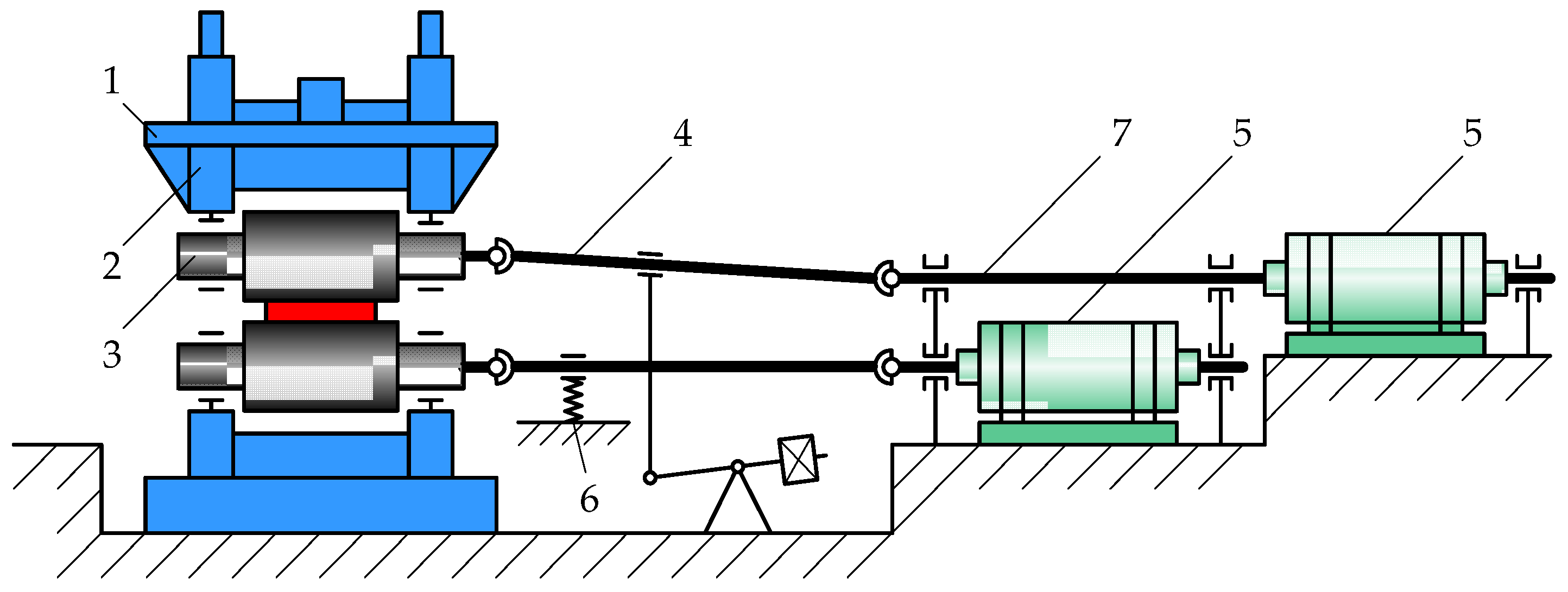
Figure 1. Working line scheme for the rolling mill’s main drive with independent roll drives: 1—roll stand; 2—housing; 3—working rolls; 4—universal spindles; 5—motors; 6—spindle balance; 7—countershaft.
Machines 10 00141 g001
Figure 2. Kinematic diagram of the transmission (a) and block diagram of the two-mass electromechanical system (b): is the uncompensated time constant; J1, J2 are the moments of inertia, first mass, and second mass; C12 is the elastic coefficient of the mechanical transmission; b is the natural damping ratio (viscous friction type); MM is the motor torque; M12 is the elastic torque of the spindle; MST is the load torque; ωref is the configured angular speed of the motor; w1, w2 are the speeds of the first mass (the motor) and the second mass (the roll), respectively; kS1 is the first mass speed feedback gain; kfT is the motor torque feedback gain.
Machines 10 00141 g002
Figure 3. The spindle image (a) and the spindle joint (b) design of the Mill 5000 horizontal stand.
Machines 10 00141 g003
Figure 4. Biting oscillograms in the mode with fully open angular gaps (a) and with closed gaps (b): window 1—motor Mmotor and spindle shaft Mshaft torques; window 2—motor speed n.
Machines 10 00141 g004
Figure 5. Angular gap reverse closing oscillograms: window 1—set (1) and actual (2) motor speeds, rpm, and open-gap speed change diagram (3); window 2—actual motor torque, kN·m.
Machines 10 00141 g005
Figure 6. Block diagram of the mechanical transmission angular gap observer: 1—dead zone block; 2—signal module calculation block; 3—relay block; 4—conjunction element; 5, 7—switch blocks (controlled switches); 6—integration block; 8—adder.
Machines 10 00141 g006
Figure 7. Diagram of the simulation model implementing the angular gap calculation algorithm.
Machines 10 00141 g007
Figure 8. The speed and torque simulation results for different angular gaps.
Machines 10 00141 g008
Figure 9. Biting with different UMD and LMD spindle angular gaps.
Machines 10 00141 g009
Figure 10. The UMD and LMD spindle motor speed (windows 1), torque (windows 2), and elastic torque (windows 3) oscillograms for open (a) and closed (b) angular gaps.
Machines 10 00141 g010
Figure 11. The spindle gap monitoring system structure.
Machines 10 00141 g011
Figure 12. A screen fragment of the Mill 5000 main control station display with the upper and lower spindles calculation results.
Machines 10 00141 g012
Table 1. Parameters of the dual-mass system model, Mill 5000.
ParameterSymbolDimensionsValue
Moment of inertia of the first moving mass (the motor)J1kg∙m2125,000
Moment of inertia of the second moving mass (the roll)J2kg∙m2114,571
Elastic coupling rigidityc12N∙m/rad5,934,842
Eigenfrequency of elastic oscillationsω12rad/s9.96
Electric drive accelerationε0rad/s21–3
Transmission gap δ Rad0.017–0.085 (1–5°)
Mean elastic torqueM12MN∙m1.9
Damping ratioβ-2.817
Attenuation decrementξ-0.172
Speed controller gainksc-19.5
Speed controller time constantTscS0.0041
Table 2. Dynamic torque and speed deviations during biting.
ParameterOscillogram Value
Open Angular PlayEarly Play Locking
Motor
Torque
MstMmaxktorqueMstMmaxktorque
kN∙munitkN∙munit
175032501.9175028501.6
Motor
Speed
ncapnminΔncapnminΔ
rps%rps%
0.820.7113.40.760.699.2
Table 3. Dynamic torque deviations of the motor and shaft when biting.
ParameterDynamic Torque Deviations in Figure 10a
Motor
Torque
Mmotor_1 (max)Mmotor_2 (max)ΔMmotor (max), %
1902109.5
Spindle
Torque
Mshaft_1 (max)Mshaft_2 (max)ΔMshaft (max), %
16923227
Publisher’s Note: MDPI stays neutral with regard to jurisdictional claims in published maps and institutional affiliations.