Article

Stability Analysis of Vaneless Space in High-Head Pump-Turbine under Turbine Mode: Computational Fluid Dynamics Simulation and Particle Imaging Velocimetry Measurement

1
Key Laboratory of Fluid and Power Machinery, Ministry of Education, Xihua University, Chengdu 610039, China
2
Research & Testing Center of Dongfang Electric Machinery, Deyang 618000, China
3
State Key Laboratory of Hydraulics and Mountain River Engineering, Sichuan University, Chengdu 610065, China
*
Author to whom correspondence should be addressed.
Machines 2022, 10(2), 143; https://doi.org/10.3390/machines10020143
Submission received: 7 January 2022 / Revised: 15 February 2022 / Accepted: 15 February 2022 / Published: 16 February 2022
(This article belongs to the Section Turbomachinery)

Abstract

:
When the Francis-type reversible pump-turbine runs under partial load, the pressure pulsation amplitude and frequency in vaneless space are high, posing a serious threat to the stability of unit operation. Water presents weak compressibility in a high-head pump-turbine, thereby affecting the amplitude–frequency characteristics of pressure pulsation. This study used numerical simulations in a model and prototype pump-turbine and particle image velocimetry (PIV) in a model pump-turbine to examine the internal flow field and pressure pulsation characteristics and determine the effect of the flow in the vaneless space on the amplitude–frequency characteristics of the pressure pulsation. The pressure pulsation amplitude–frequency characteristics were verified through prototype tests. The effects of the weak compressibility of the water on the propagation law of pressure pulsation throughout the flow passage of the prototype and model pump-turbine were roughly similar but exhibited certain differences. Considering the weak compressibility of water, the pressure pulsation fluctuations in each flow passage of the prototype and model pump-turbine exhibit varying degrees of improvement, which is more obvious at the prototype scale. Therefore, the pressure wave disturbance caused by the weak compressibility of the water has different effects on the prototype scale and model scale of the high-head Francis pump-turbine.

1. Introduction

Currently, pumped-storage power stations are globally used as energy storage devices with huge capacities. As of 2020, the total installed capacity of China’s pumped-storage power plants was 40 million kilowatts. A pump-turbine is the core component of a pumped-storage power station, and its operational stability directly affects the benefit of the power station and the stability of the power grid. Due to the increasing head of pumped-storage units, the water embodies weak compressibility. This characteristic has an impact on both the flow and pressure pulsation characteristics inside the unit and is of high research value.
In pump-turbines, the vaneless space between the guide vane and the runner blades is the most unstable region of flow [1,2,3]. The rotating stalls in the vaneless space [4,5] and the rotor–stator interaction (RSI) [6,7] threaten the stable operation of the pump-turbine. The direct manifestation of the hydraulic stability is the pressure pulsation phenomenon, and the vortex flow in the vaneless space and RSI effects are the main factors that influence the pressure pulsation in the vaneless space [8,9,10], where the RSI effects cause the high-frequency component of the pressure pulsation, while the vortex flow leads to the low-frequency component. The main frequencies of pressure pulsations obtained from model tests and prototype tests in previous studies are basically the same, but the difference in amplitude prediction is relatively large. Furthermore, this problem is clarified by the comparison between numerical simulation and model or prototype tests. The model test value is significantly smaller than the prototype test value under partial load. The RSI frequency second harmonic amplitude of pressure pulsation in the high-load area numerically was simulated compared to the prototype test in the vaneless space was severely underestimated. Research studies attribute this to the extremely high pressure inside the unit at high-head conditions that caused the water to be compressed [11,12,13]. Trivedi et al. [14,15] studied the RSI between the guide vane and the runner and the evolution of the unsteady flow structure in the runner under no-load conditions and runaway conditions by means of compressible simulations, and Wang [13] studied the internal flow field and pressure pulsation characteristics of a model pump-turbine under different operating conditions by considering the weak compressibility of water. The compressible simulation results were closer to the model test results. As pump-turbine design proceeds towards high head, capacity, and speed, the influence of weak water compressibility on pump-turbine stability plays an increasingly important role in the design. Hence, in-depth investigation of the effects of weak water compressibility in pump-turbines is required.
Particle image velocimetry (PIV), as a transient, multi-point, non-contact hydrodynamic velocity measurement method, has been widely used in researching the internal flow of fluid machinery in recent years. PIV technology is widely used in fluid research owing to its good visualization performance and accurate results [16,17,18,19]. PIV is widely used in the shooting of vortices in fluids [20,21,22,23]. The PIV test process only needs a CCD camera, laser, and synchronizer to measure the flow velocity in a transparent pipe without direct contact with the fluid. Thus, the PIV test process has the advantages of convenient installation, simple operation, and strong anti-interference ability [24,25,26]. In comparison with other non-contact measurement methods (such as LDV and ultrasonic measurement), PIV has the advantages of high accuracy, large imaging area, easy installation, and strong anti-interference ability [27].
Yan et al. [28] used the PIV test method to study the flow regime inside the runner of a Francis pump-turbine and determined the influence of the impingement angle of the runner blade and the GVO on the flow regime. Tang [29] and Xu [30] used the PIV test method to study the inter-blade vortex of a Francis turbine and obtained the initiation and development of the inter-blade vortex. The authors also used the PIV test method to test the pump-turbine under four-quadrant working conditions. The flow regime in the vaneless space of the pump-turbine was observed, and the vortex change and development laws were obtained [31]. Liu et al. [32] studied the vortex structure of the vaneless space of two different runners in multiple turbine working conditions under different working conditions through the PIV test. Moreover, they studied the working characteristics of the unit under unstable conditions.
In this study, we employed the PIV test method to test the flow characteristics in the vaneless space of a model Francis-type pump-turbine under turbine modes. The internal flow fields of the model and prototype pump-turbine were also numerically simulated using computational fluid dynamic (CFD) methods, and the pressure pulsation characteristics inside the units were investigated considering the low compressibility of water.

2. Computational Fluid Dynamic Simulation

2.1. Geometry and Mesh

The typical parameters of the model and prototype pump-turbine are listed in Table 1. The diagram of the model pump-turbine is shown in Figure 1.
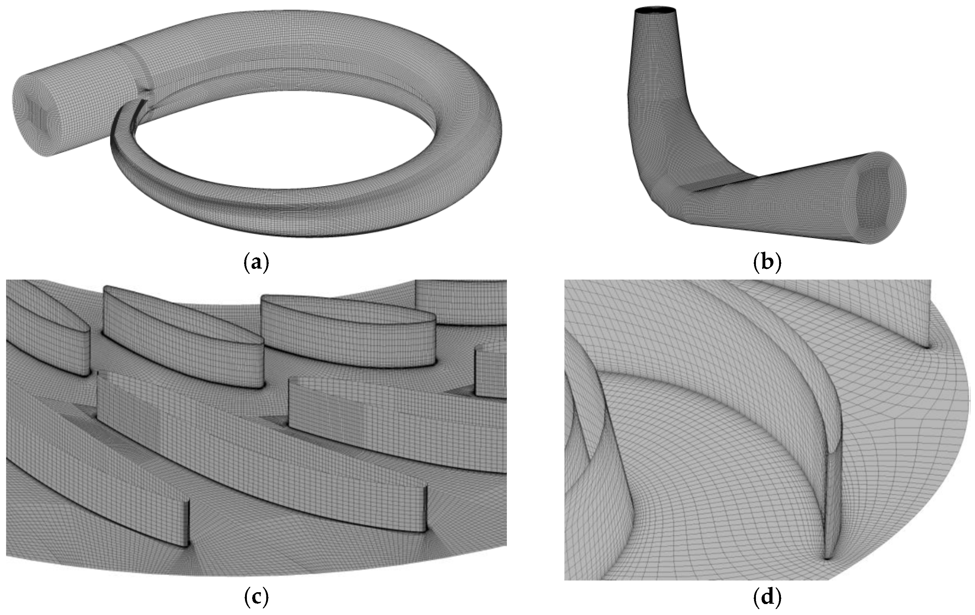
Using ICEM and Turbogrid, the model pump-turbine was divided into a hexahedral mesh. The grid is shown in Figure 2. The grid independence was also verified. When the number of grids reached 4.9 million, the efficiency and head fluctuation were less than 0.05%. This value met the accuracy required by the numerical simulation. The number of grids in each part is shown in Table 2. The average value of y+ in the near-wall region of the runner and guide vane was less than 15, which met the requirements of the turbulence model.

2.2. Boundary Conditions and Operating Points

SST k-ω turbulence model [33,34,35] was used in the CFD simulation by ANSYS CFX. The operating point parameters are listed in Table 3. The flow inlet and opening outlet are adopted. The conditions of the inlet and speed of rotation of the runner were selected according to the results of the model test. For interface processing, the general grid interface was used to connect the parts. In the interface type in the stable calculation, type None was used for the static interface, and the frozen rotor approach was applied for the dynamic and static interfaces. In the unstable calculation, the static–static interface still adopted the type None, whereas the dynamic–static interface adopted a transient rotor–stator interaction. The calculation time step was 1/360 of the runner rotation period, 0.000340977 s for the prototype and 0.000138899 s for the model. A root mean square of residuals of 10–5 was used as the convergence condition for the iterative calculation. Further, 20 runner rotation periods were calculated, and the last 5 periods were selected for analysis. The unit flow and unit speed are expressed as follows:
n 11 = n D 2 H ,
Q 11 = Q D 2 2 H ,
where n11 is the unit speed (rpm), Q11 is the unit flow (L/s), n is the speed (rev/min), Q is the flow (L/s), H is the working head (m), and D2 is the nominal diameter of the runner (m).
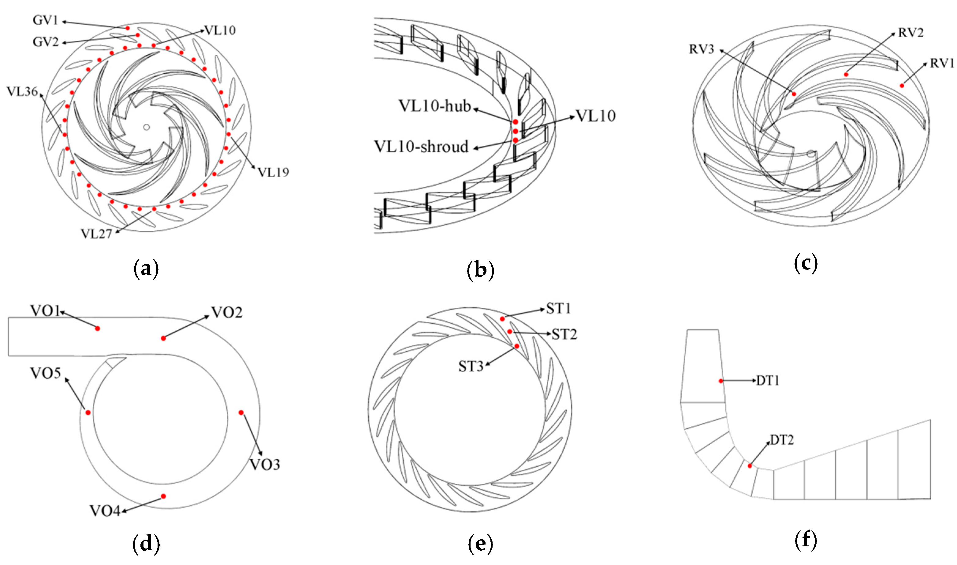
Figure 3 shows the location of pressure pulsation monitoring points during the transient calculation, where 108 of these are located in the vaneless space, with three layers of 36 points each. The monitoring points in the vaneless space are named in a clockwise direction, and owing to space limitations, some monitoring points such as VL36 and VL10 are marked in.

2.3. Weakly Compressible Equation

The equation expressing the state of the water is based on the relationship between the water’s density and pressure, determined from the acoustic pressure Equation (3) [11,36].
ρ = ρ 0 + ( P P 0 ) / c 0 2
where ρ is the actual density of water; ρ 0 is the reference density of water, 998 kg/m3; P 0 is the reference pressure, 101,325 Pa; and c 0 is the speed of sound, 1400 m/s.

2.4. Computational Fluid Dynamics Results

The dimensionless pressure coefficient, Cp, and ΔH/H are reference values for quantifying the intensity of pressure pulsations in pump-turbines, as shown in Equation (4).
C p = p i p ¯ ρ g H × 100 %
Δ H H = p i max p i min ρ g H × 100 %
where Cp is the dimensionless pressure pulsation coefficient (%), p i is the corresponding pressure at point i (Pa), p ¯ is the time-averaged pressure, H is the head (m), ρ is the density of water, and g is the gravitational acceleration. ΔH is the pressure pulsation peak-to-peak value, m; p i max , p i min is the corresponding maximum and minimum pressure values at point i, Pa.
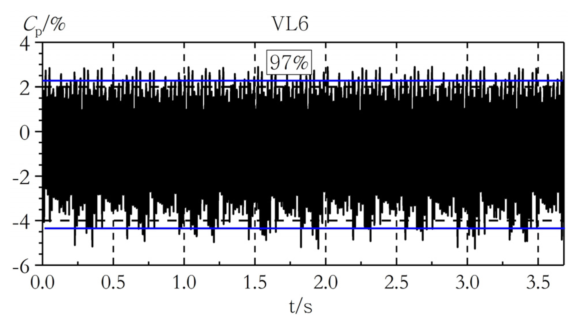
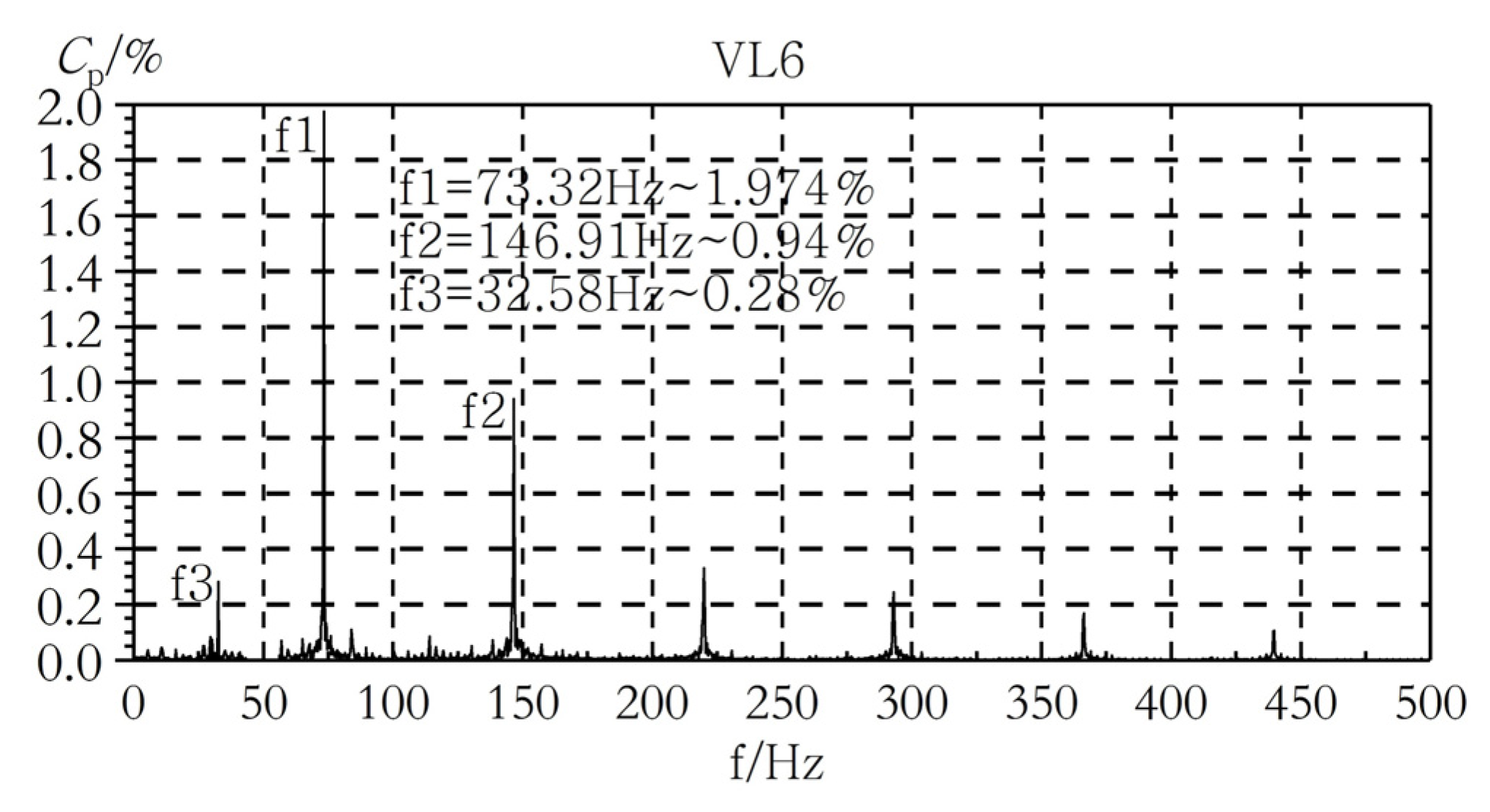
Figure 4 and Figure 5 show the time-domain and frequency-domain plots of the pressure pulsation monitoring point, VL6 of the prototype test, respectively, where f1 is the blade-passing frequency (BPF), 9fn. As seen in the figure, the primary frequency of the pressure pulsation monitoring point, VL6, in the vaneless space of the prototype test was BPF 9fn (i.e., 73.32 Hz), and the relative pressure pulsation amplitude was 1.97%. The secondary frequency was 18 fn, that is, 146.91 Hz, and the relative pressure pulsation amplitude was 0.94%. Additionally, the relative pressure pulsation amplitude, 4fn, was relatively small (32.58 Hz) at a relative pressure pulsation amplitude of 0.28%.
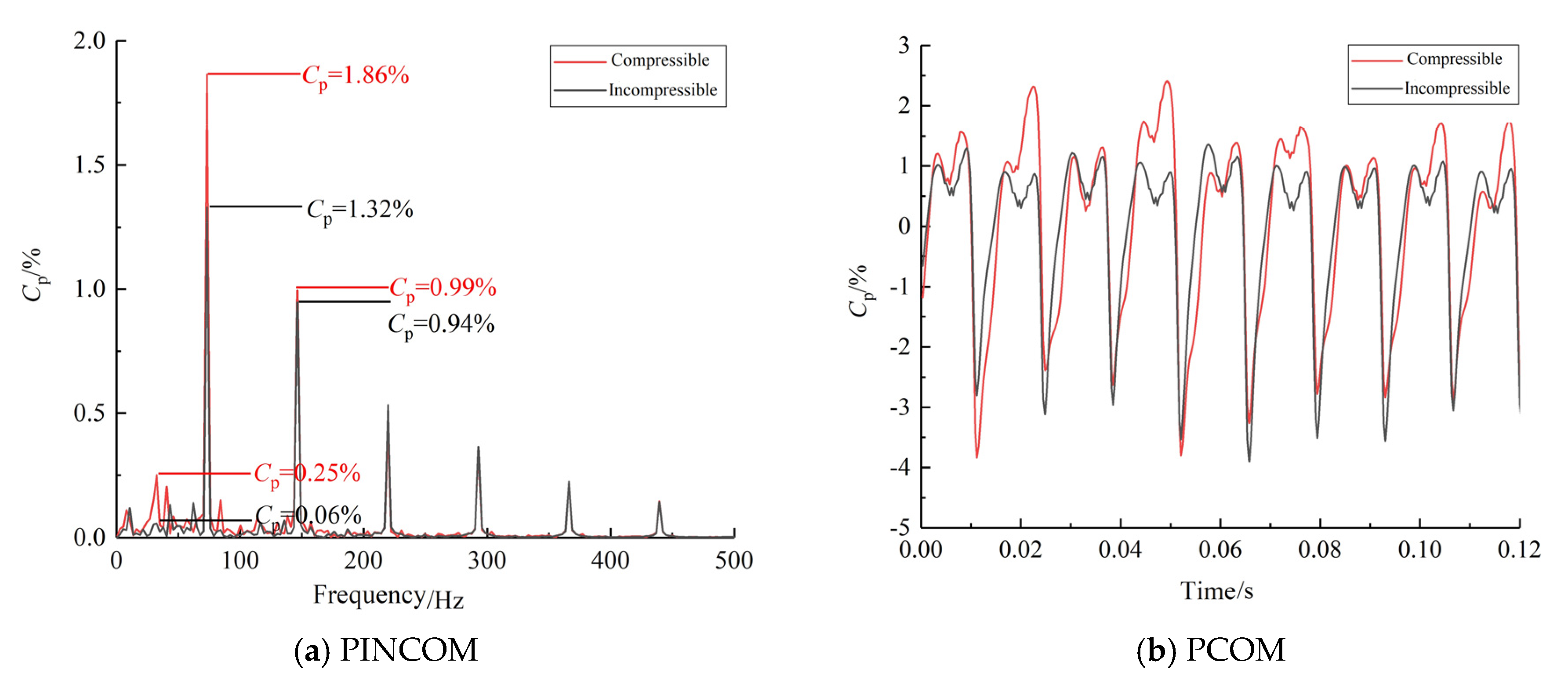
Figure 6 shows the frequency-domain and time-domain diagrams of pressure pulsation considering the compressible and non-compressible cases of water. Evidently, both the compressible and non-compressible simulations can better reflect the main frequencies in the prototype test, but the difference in their prediction of the main frequency amplitude is relatively large. The main frequency f1 relative pressure pulsation amplitude is 1.32% in the incompressible simulation, while the f1 relative pressure pulsation amplitude is 1.86% in the compressible simulation, which is closer to the prototype test results. In addition, the incompressible simulation fails to obtain the characteristic frequency, f3, while the relative pressure pulsation amplitude of the characteristic frequency f3 in the compressible simulation is 0.25%. Figure 6b shows the time-domain diagram of the pressure pulsation of the pressure monitoring point VL6 in the vaneless space within one rotating cycle of the runner considering the compressible and non-compressible cases of the water, and the pressure pulsation in the vaneless space within one rotating cycle of the runner in both the compressible and non-compressible simulations shows periodic changes, but the relative pressure pulsation amplitude in the weakly compressible condition is larger than that in the non-compressible condition. Therefore, the results yielded when the weak compressibility of the water in the numerical simulation is considered are closer to those of the prototype test than the results yielded when the compressibility of the water is not considered.
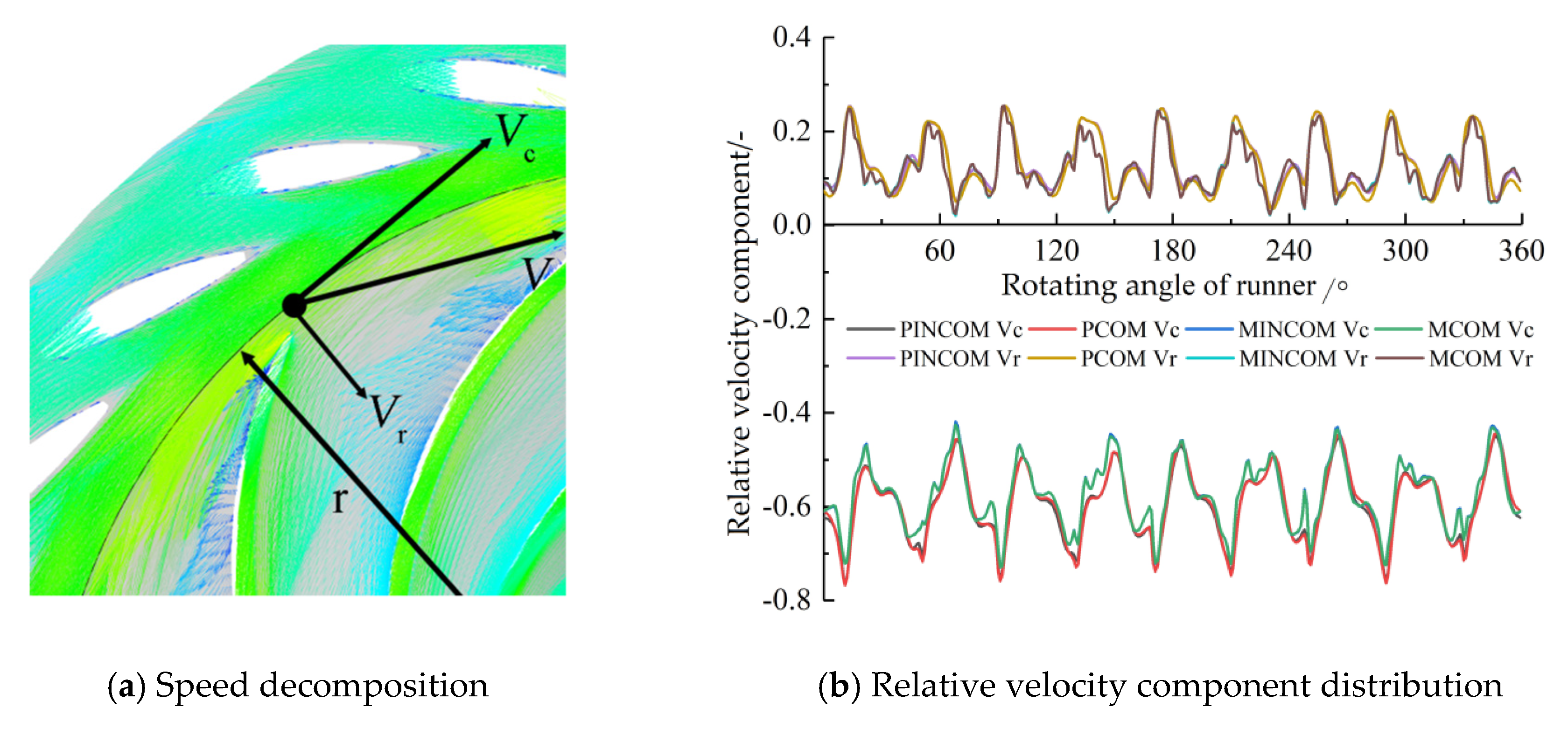
The internal flow field characteristics of the prototype and the model were compared and analyzed, and Figure 7 shows the relative velocity distribution of the annulus within the vaneless space.
Figure 7 shows that the water flow in the flow field in the vaneless space under rated operating conditions flows into the runner through this ring surface, showing regular velocity fluctuations corresponding to the number of runner blades, which indicates that the hydraulic instability in the flow field in the vaneless space of the model pump-turbine and the prototype pump-turbine under this operating condition is mainly generated by RSI, where the potential flow disturbance phenomenon is obvious. The CFD results of compressible simulation and incompressible simulation are relatively consistent.
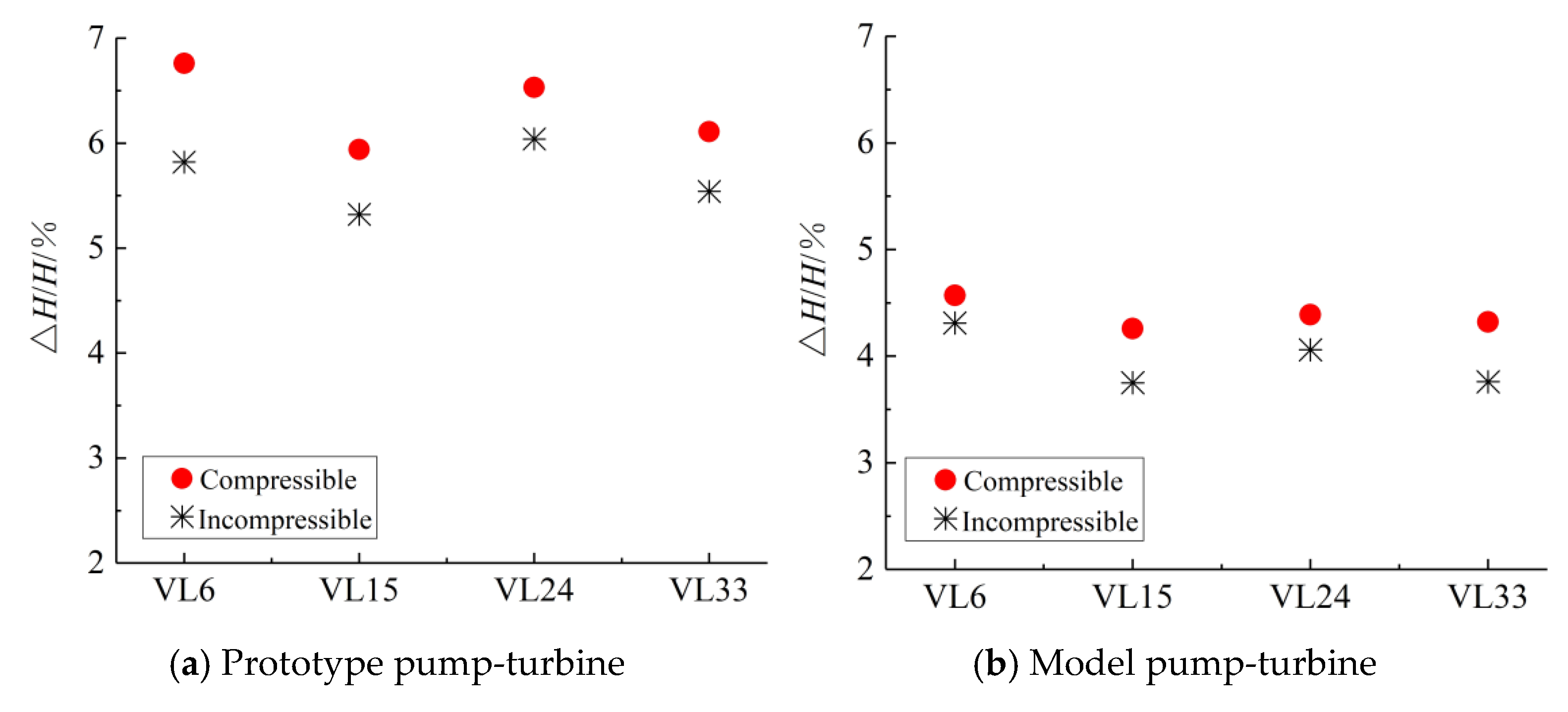
The relative amplitude of pressure pulsation ΔH/H at monitoring point VL6, monitoring point VL15, monitoring point VL24, and monitoring point VL33 in the vaneless space of the prototype and the model machine were compared and analyzed as shown in Figure 8. The positions of the four monitoring points were symmetrical with respect to the central axis of the runner, and the monitoring points were separated by 90° from each other, as shown in Figure 3.
Comparison of the relative pressure pulsation amplitude of the four monitoring points in the vaneless space of the prototype and the model machine indicates that the distribution pattern of the relative pressure pulsation amplitude in the vaneless space of the prototype pump-turbine is consistent with that of the model pump-turbine, but the relative pressure pulsation amplitude in the vaneless space of the prototype pump-turbine is larger than that of the model pump-turbine, and the compressible simulation is larger than the incompressible simulation. This difference in the relative pressure pulsation amplitude caused by the compressibility of water is more obvious in the prototype pump-turbine.
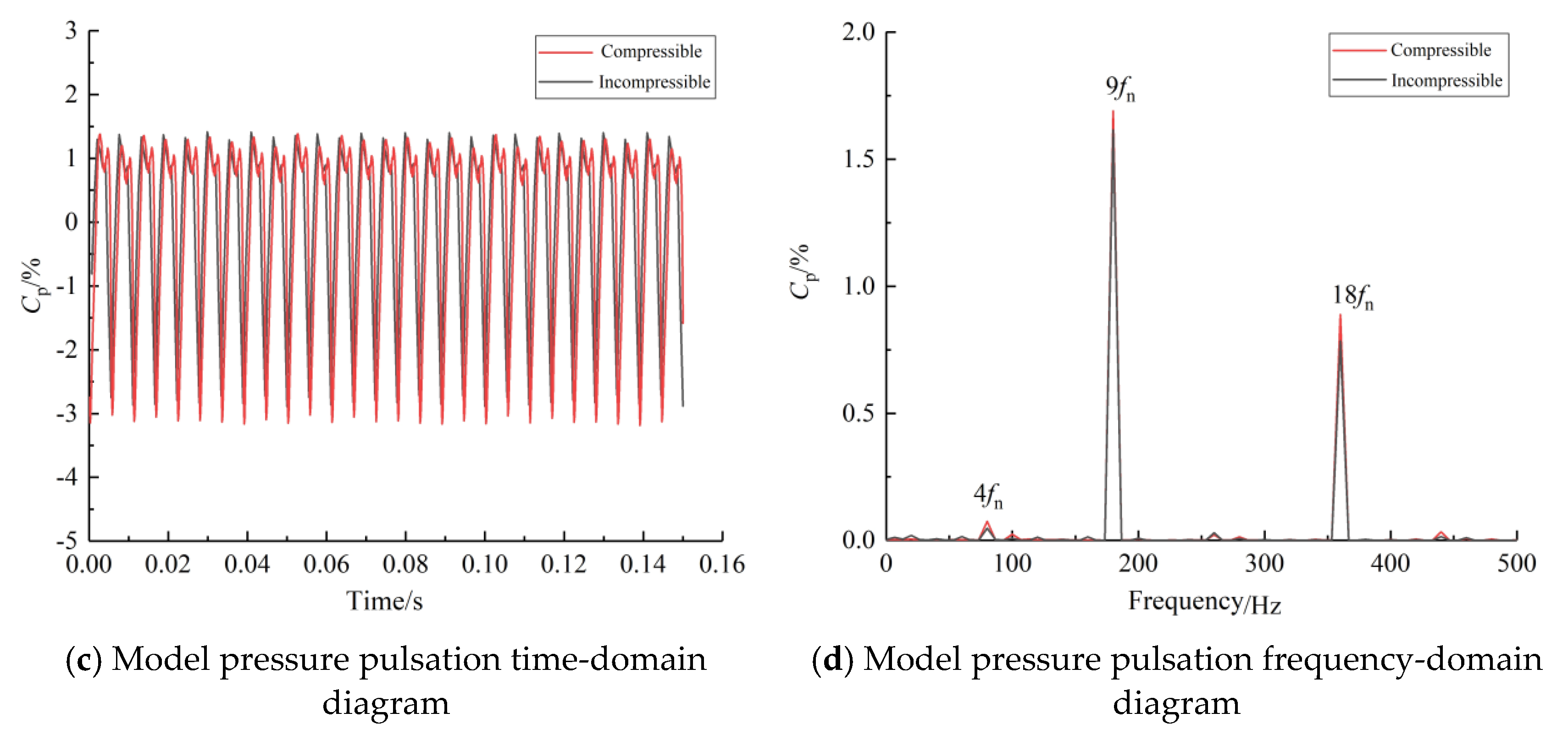
The pressure pulsation time-frequency characteristics of the prototype and model pump-turbine vaneless space monitoring point VL6 are further analyzed, as shown in Figure 9, where the blade rotation frequency fn is 8.15 Hz and 19.99 Hz for the prototype pump-turbine and model pump-turbine, respectively, under the rated operating condition of the turbine, and its BPF is 9fn.
The main frequencies of pressure pulsation in the vaneless space of both the prototype and the model pump-turbine are BPF, and its harmonic frequencies are 9fn and 18fn. In addition, there is a relatively small pressure pulsation amplitude of 4fn. The blade-passing frequency and its harmonic frequencies 9fn and 18fn are RSI frequencies. 4fn is obtained from the upward propagation of the runner channel.
Whether compressibility is considered or not, the numerical simulation results are consistent with the main frequency of pressure pulsation of the test results, but there is still a certain difference in amplitude. Under the incompressible condition, the main frequency amplitude of pressure pulsation in the vaneless space of the prototype pump-turbine is significantly smaller than that of the prototype test results, and the main frequency amplitude of pressure pulsation in the vaneless space of the model pump-turbine is lower than that of the model test results, but the difference is smaller. Under the weakly compressible condition, the main frequency amplitude of pressure pulsation in the vaneless space of the prototype and model pump-turbine is increased, and the main frequency amplitude of pressure pulsation in the vaneless space of the prototype pump-turbine is higher than that of the model pump-turbine when the weak compressibility of the water is considered. Generally, when considering the weak compressibility of water, the main frequency amplitude of pressure pulsation is closer to the experimental value, and it is more obvious in the numerical simulation of the prototype pump-turbine. This is because the speed of sound in water is approximately 1400 m/s, the wavelength is approximately 5–30 m, the RSI frequency of the pump-turbine is approximately 50–200 Hz, and its corresponding acoustic wave wavelength is similar to the scale of the prototype pump-turbine, so this pressure wave perturbation caused by the compressibility of the water causes acoustic resonance in the flow field and enhances its pressure pulsation amplitude.

3. Particle Image Velocimetry Methods

The pressure pulsation amplitude in the vaneless space is affected by compressibility and the vortex motion in the vaneless space, which is examined using the PIV test.

3.1. Particle Image Velocimetry System and Model Pump-Turbine Parameters

The PIV test system is composed of tracer particles, a pulsed laser and sheet light source lens group, a CCD camera, a synchronizer, and a special workstation. The main technical indicators of the PIV test system are listed in Table 4. The parameters of the model pump-turbine used in the test are consistent with those of the CFD model pump-turbine.

3.2. Test Site

The structural system of the test bench includes a high-pressure water tank, a model water pump-turbine test section (including a dynamometer), a low-pressure water tank, and a vacuum pump system, which is a closed-loop test system. The system was supplied by two 24SA-10 single-stage double-suction centrifugal water pumps. The pumps were connected to two 850 kW bi-directionally rotating DC motors. The DC motors were powered by two sets of fully digital DC speed-regulating devices. The pump unit can realize stable operation within a range of 400–1000 r/min. The maximum lift of the single pump was 85 m. The maximum flow rate was 1.0 m3/s, and the maximum speed was 1000 r/min. The maximum water head of the test bench was 170 m, and the speed stabilization accuracy was 0.1%. The diameter of the high-pressure pipeline of the system was 500 mm, and that of the low-pressure pipeline was 700 mm. A bi-directional electromagnetic flowmeter was used for flow calibration. The diameter of the high-pressure water tank and the low-pressure water tank of the test bench was 2.4 m. These large containers stabilize the water flow before and after the model unit, and the water flows through the electromagnetic flowmeter. The parameters of the test bench are listed in Table 5.
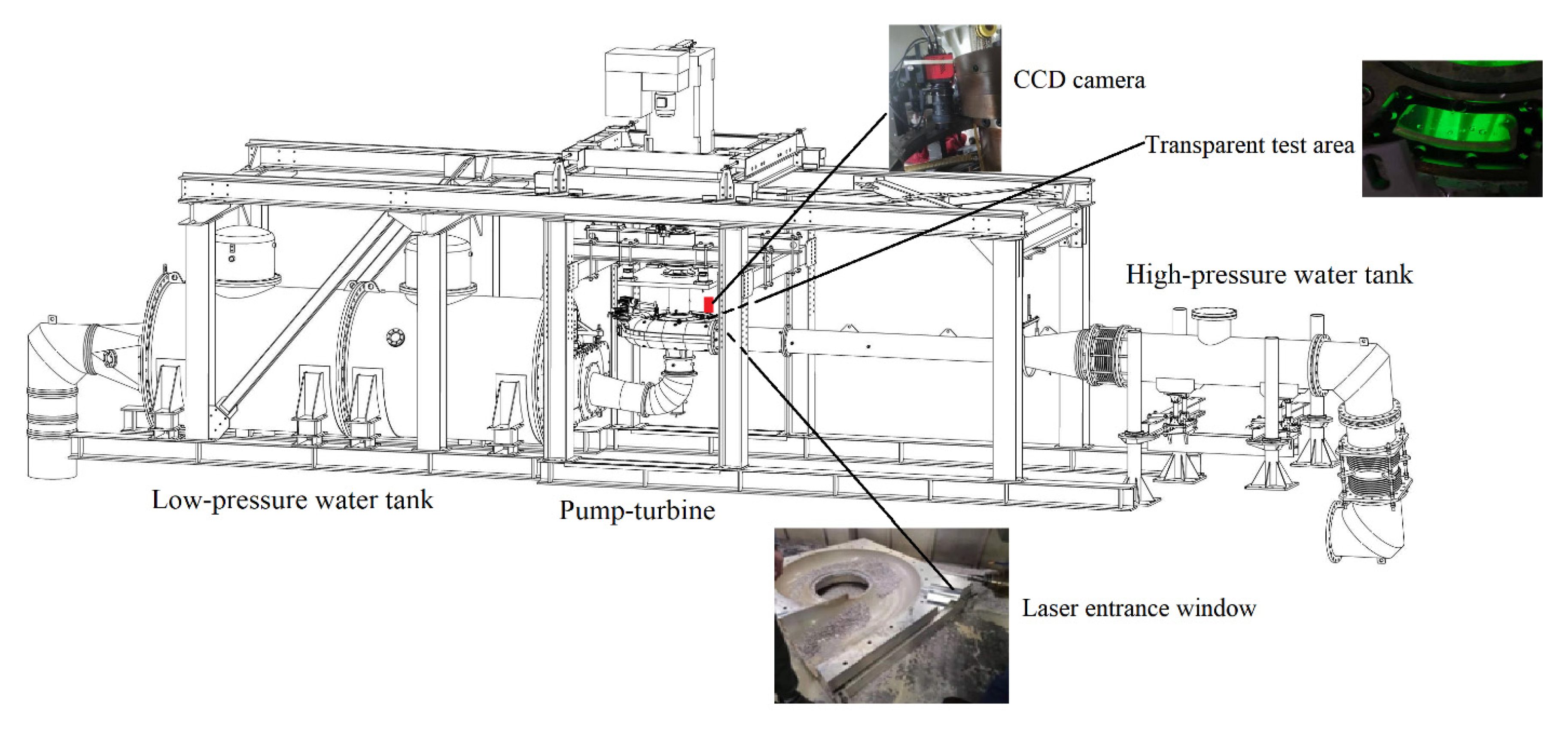
The position and arrangement of the camera are shown in Figure 10. The imaging area is the position of the vaneless space between the runner and guide vane, and the imaging area is determined by the position of the two screws on the end shaft of the guide vane. The pulsed laser was directed to the experimental observation area from the transparent window at the volute. The test operating points are listed in Table 6.

3.3. Test Results

Figure 11 shows the internal flow field in the vaneless space under different operating conditions.
Under 50% load conditions, the vortex structure in the vaneless space is relatively large and is distributed singly in the observation area, and the vortex rotation is clockwise. At the operating point, OP1, the vortex structure is relatively small, and the vortex structure appears close to the runner outlet, while at OP2 and OP3, where the unit speed is relatively high, this vortex structure is very large, and the pressure at the center of the vortex is extremely low owing to the very high vortex center flow velocity at this time. This local low pressure caused by the vortex causes periodic disturbance to the high-pressure flow field in the vaneless space where the rotation of the runner significantly contributes to the high amplitude of pressure pulsation in the vaneless space under partial load.
Under the 75% load condition, the flow field in the vaneless space is relatively stable and smooth at the lower speed, OP4, but as the unit speed increases, a clockwise rotating vortex and a counterclockwise rotating vortex are distributed in pairs at OP5 and OP6, and the vortex structure is reduced to a certain extent compared with the 50% load vortex structure. At 100% load condition, the flow field in the vaneless space is relatively stable, the vortex structure in the vaneless space is very small at OP8 and OP9, and the distribution of vortex is not even observed at OP7.
At 50% load condition, the unsteady vortex structure in the vaneless space is single vortex distribution, and the vortex structure is larger. When the unit load increases to 75%, the vortex structure changes from a single vortex structure to a double vortex structure, and the vortices are distributed in pairs and rotate in opposite directions. With the progressive increase in load, the unsteady vortex structure in the vaneless space is further reduced at 100% load condition, and the vortex structure is changed to a single vortex structure with a smaller vortex structure. At the same load, the vortex structure increases with the increase in unit speed, and the position moves toward the guide vane exit runner.
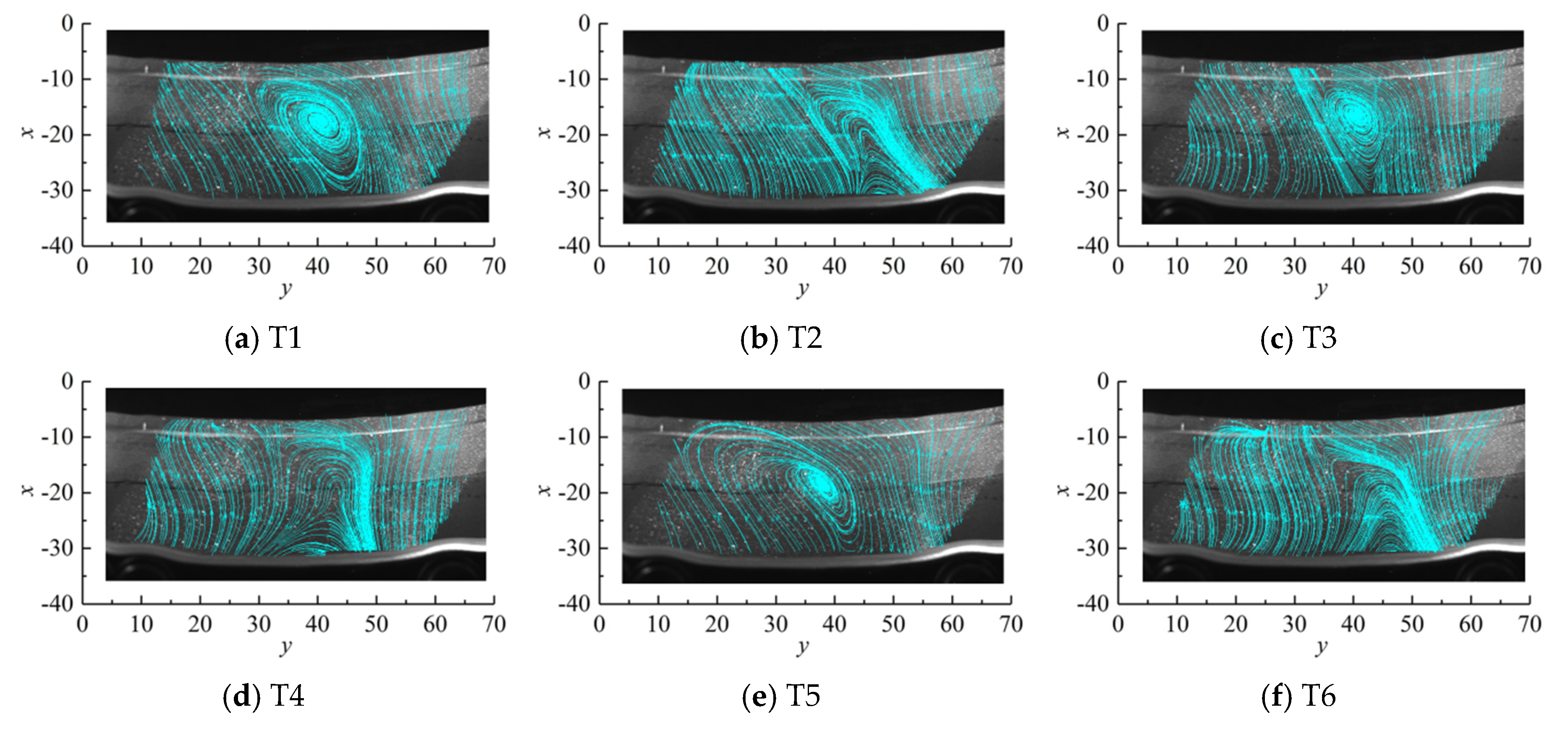
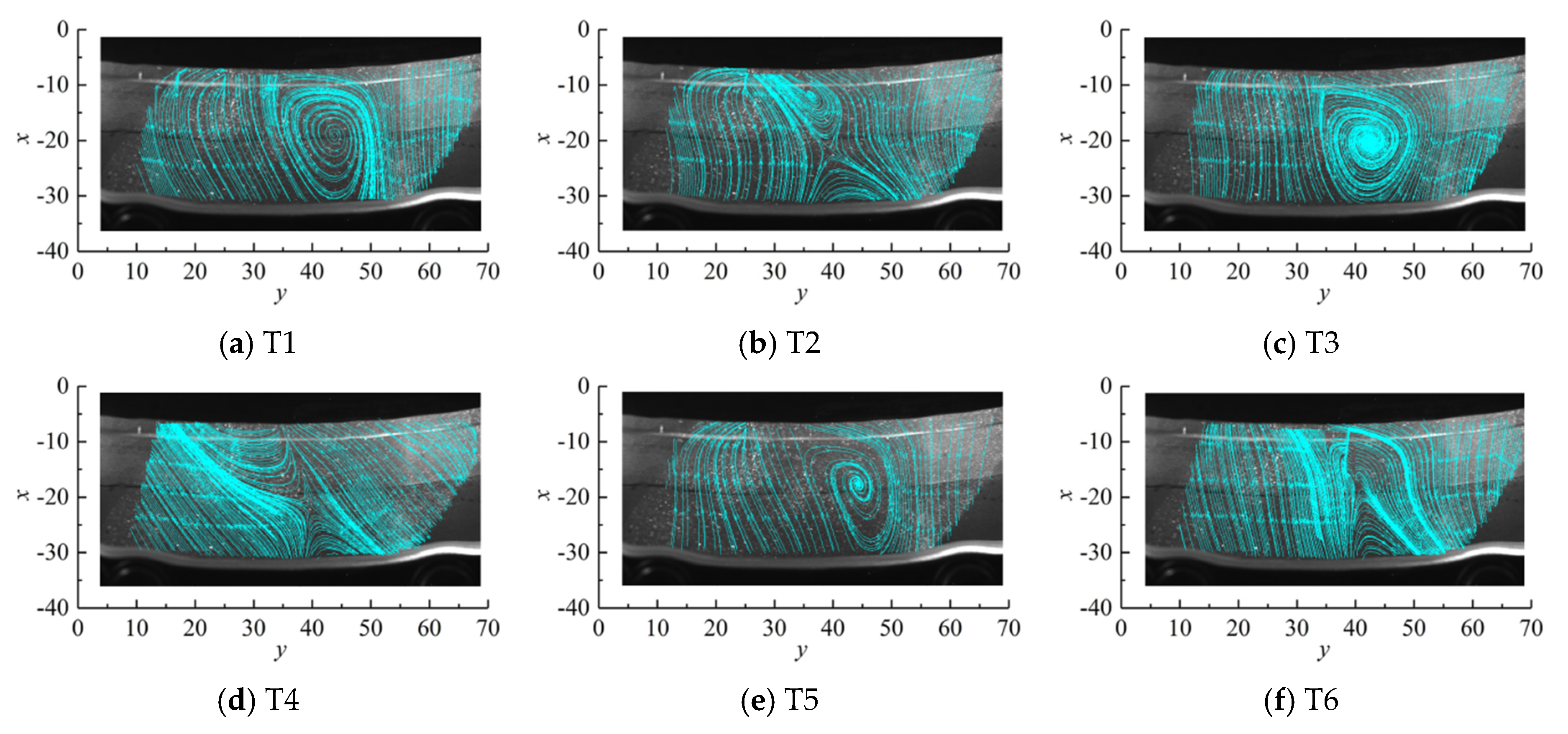
Analysis of continuous images of OP1, 2, and 3 test results.
Figure 12, Figure 13 and Figure 14 show the variation of the internal flow field in the vaneless space over time at different speed operating points, OP1, OP2, and OP3, of the unit under 50% load condition of the turbine, respectively. The rotor rotation times for one revolution at working points OP1, OP2, and OP3 are 0.0525 s, 0.0510 s, and 0.0502 s, respectively, and the sampling frequency is 15 Hz. To analyze the variation of the internal flow field in the vaneless space over time, six different moments, T1, T2, T3, T4, T5, and T6, of the same time interval ΔT are selected.
At 50% load, the flow regime inside the vaneless space is more turbulent; large-scale unsteady vortex structures appear frequently in the observation cycle and are observed once every ΔT apart. At operating point OP1, the unsteady vortex structure in the vaneless space is located near the runner inlet side, and the vortex structure is relatively small. As the rotational speed increases, the unsteady vortex structure in the vaneless space becomes larger at operating points OP2 and OP3, and the flow regime in the vaneless space deteriorates. The large-scale unsteady flow structure appears in the vaneless space between the guide vane outlet and the runner inlet, and this unsteady vortex structure with high frequency and large-scale structure disturbs the flow field in the vaneless space, thereby decreasing the stability of the flow field inside the vaneless space.
This unstable vortex structure is generated in the runner channel, so its characteristic frequency is related to the rotating frequency of the runner blades, and because of its development to the vaneless space, it intensifies the RSI effect, so this unstable vortex structure causes the main frequency amplitude of the pressure pulsation in the vaneless space to increase significantly, i.e., the BPF 9fn. With the change of working conditions, in the operating range of the unit, the unit load is attenuated as it increases and is enhanced as the unit speed increases in the same load condition.

4. Propagation Law of Pressure Pulsation in the Vaneless Space

The source of high-frequency pressure pulsation in the vaneless space, which is the location of the strongest pressure pulsation in a pump-turbine, was analyzed in CFD and PIV studies; therefore, the propagation law was analyzed.

Full-Flow Channel Pressure Pulsation Characteristics

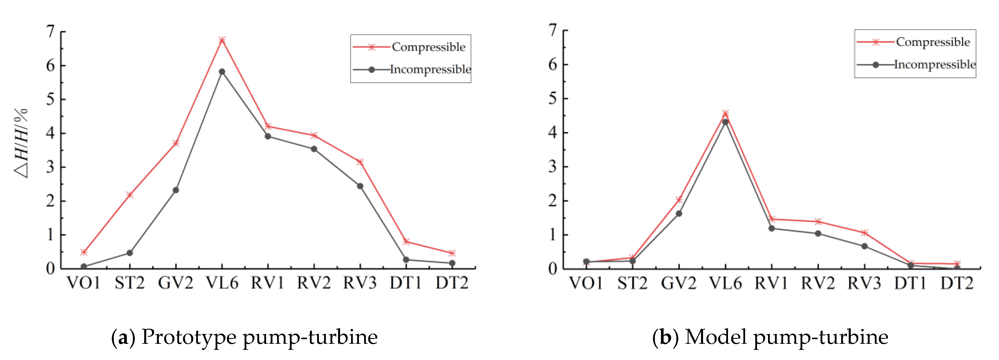
Figure 15 shows the relative pressure pulsation amplitude distribution in the full-flow channel of the prototype and model pump-turbine under compressible and incompressible conditions, and the pressure pulsation monitoring points were selected as VO1, ST2, GV2, VL6, RV1, RV2, RV3, DT1, and DT2. A total of nine monitoring point locations were compared and analyzed.
Figure 15 shows that the relative pressure pulsation amplitude distribution pattern is the same for the prototype and model pump under compressible and incompressible conditions, the strongest pressure pulsation area is located in the vaneless space, and the relative pressure pulsation amplitude gradually decreases upstream and downstream along the vaneless space. Regardless of whether the weak compressibility of the water is considered, the pressure pulsation intensity of the prototype pump-turbine in the full-flow channel exceeds that of the model pump-turbine. The compressible simulation results are higher than the incompressible simulation results, and this difference in numerical calculation owing to the consideration of the weak compressibility of the water is more obvious in the prototype pump-turbine.
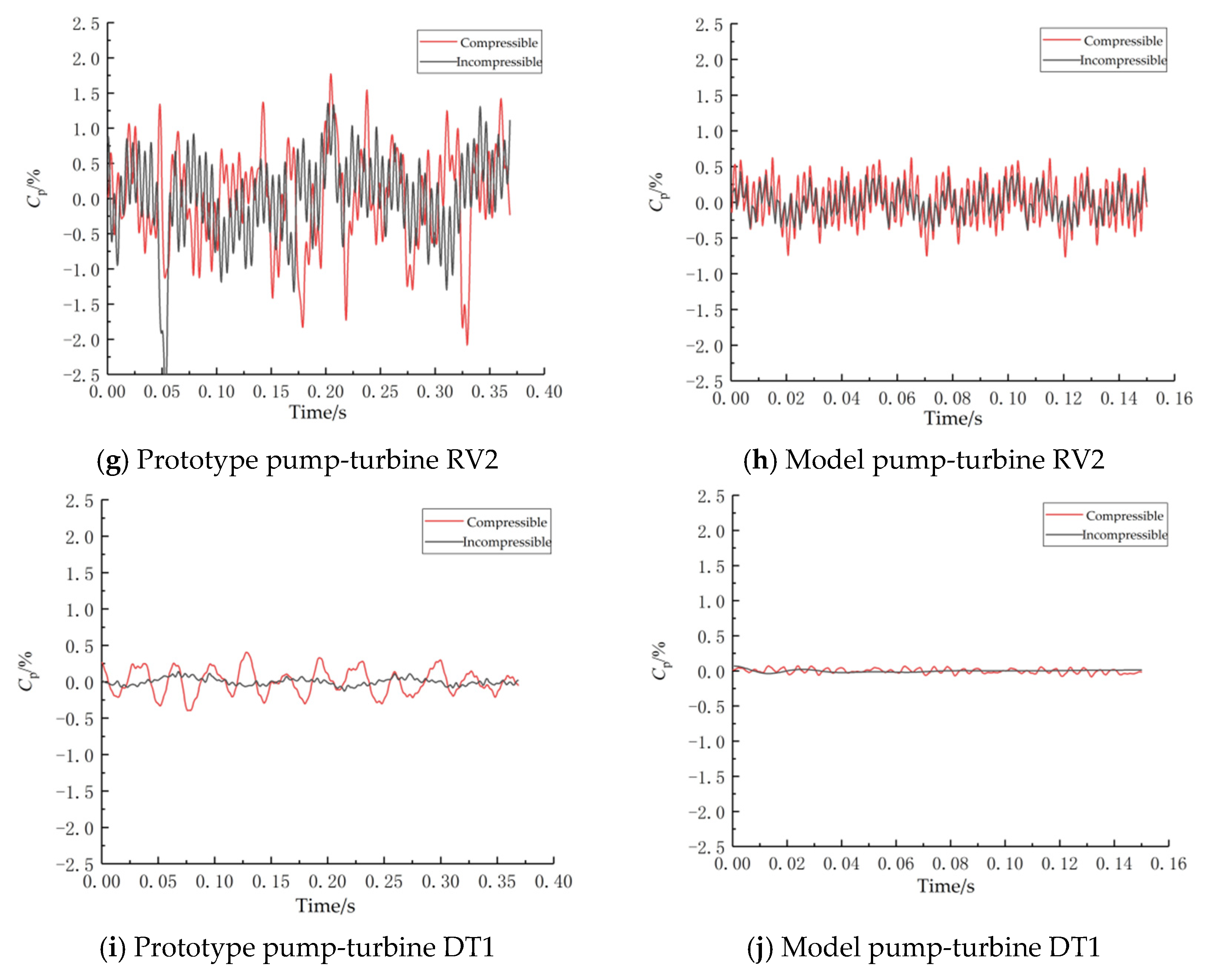
Figure 16a,b shows that the pressure pulsation at monitoring point, VO1, in the inlet runner of the prototype pump-turbine spiral casing is mainly affected by the vortex rope of the draft tube under the incompressible condition, showing low-frequency vibration with low amplitude, while the pressure pulsation under the compressible condition is mainly affected by the RSI, showing amplitude fluctuations corresponding to the number of runner blades. The pressure pulsation at monitoring point VO1 of the model pump-turbine shows the characteristics of high-frequency vibration, but the fluctuation pattern of pressure pulsation under incompressible conditions is related to the number of runner blades, and there are nine fluctuations in the runner cycle, which is influenced by RSI, and four fluctuations of pressure pulsation under compressible conditions are four times in a runner cycle, which is related to the flow separation in the runner.
In Figure 16c,d, the pressure pulsation at the stay vane monitoring point ST2 of the prototype pump-turbine is affected by both the vortex rope of the draft tube and RSI under incompressible conditions, and the pressure pulsation shows the characteristics of both low-frequency vibration and high-frequency vibration. Further, a significant increase is observed in the amplitude of the pressure pulsation under compressible conditions, where one of the high-frequency components is significantly enhanced. The time-domain characteristics of the pressure pulsation at the stay vane runner monitoring point ST2 of the model pump-turbine are relatively consistent, both being high-frequency vibrations related to the number of blades.
The pressure pulsation fluctuation at the guide vane monitoring point GV2 of the prototype and model pump-turbine in Figure 16e,f is affected by the RSI under both compressible and incompressible conditions, showing a regular fluctuation related to the number of blades, but the pressure pulsation amplitude fluctuation of the prototype pump-turbine is more obvious under compressible conditions. In Figure 16g,h, the fluctuation of the pressure pulsation amplitude at the prototype and model pump-turbine runner monitoring point RV2 is mainly influenced by the RSI, which is related to the number of guide vanes, and the pressure pulsation fluctuation of the prototype pump-turbine is more obvious than that of the model pump-turbine.
In Figure 16i,j, the straight cone section of the draft tube of the prototype pump-turbine, DT1, mainly vibrates at low frequencies under incompressible conditions, with small pulsation amplitudes, while under compressible conditions, the pressure pulsation fluctuations are significantly enhanced, and the frequency of amplitude fluctuations is significantly increased, with fluctuation patterns related to the phenomenon of flow separation in the runner. The pressure pulsation fluctuations of the model pump-turbine draft tube straight cone section monitoring point DT1 in the incompressible conditions are small and almost tend to be stable, while the pulsation amplitude of low-frequency fluctuations appears in the compressible conditions.
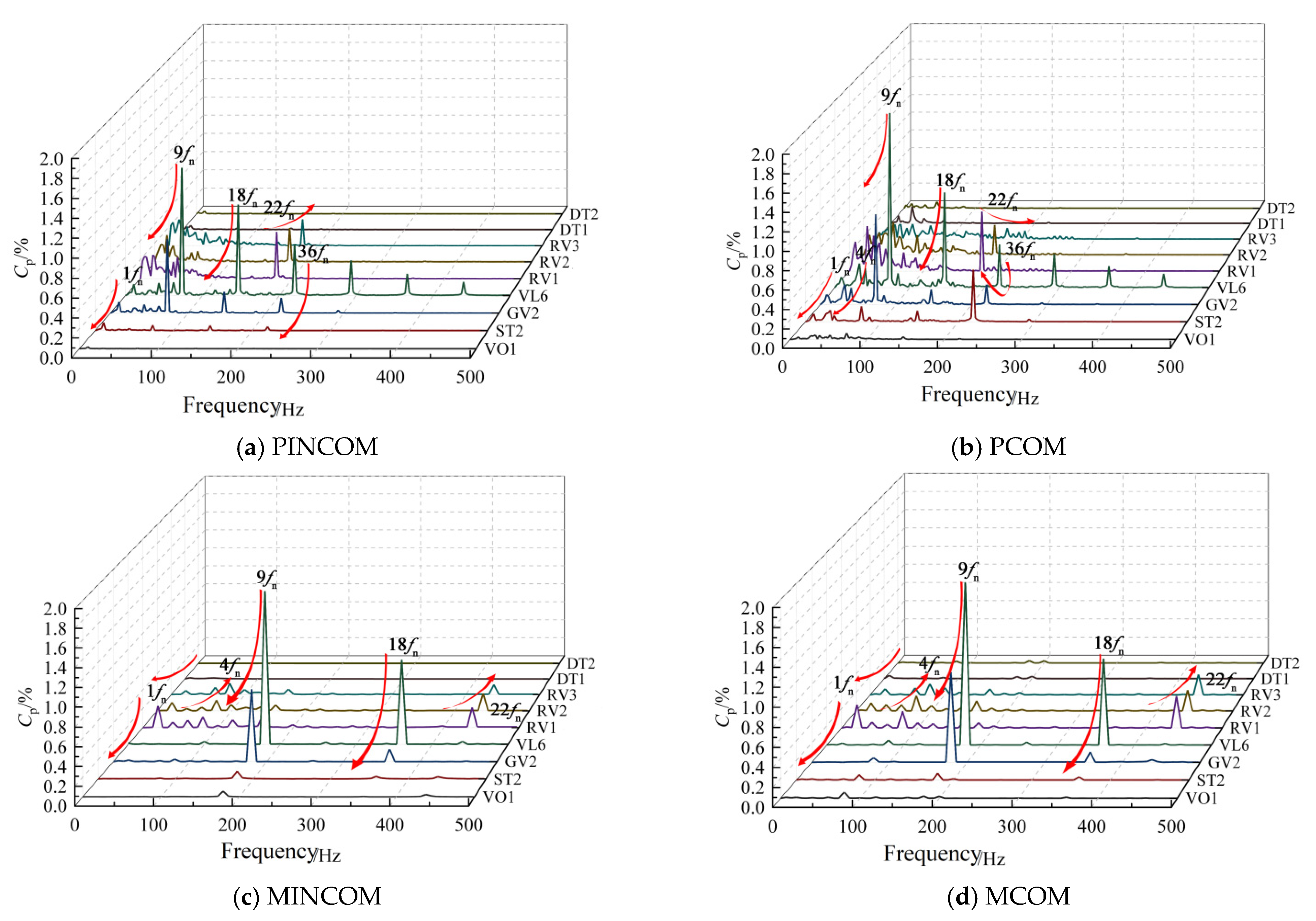
The frequency-domain characteristics of the full-flow channel pressure pulsation for the prototype and model pump-turbine under compressible and incompressible conditions are shown in Figure 17.
The similarities in the propagation pattern of the characteristic frequency of pressure pulsations along the flow channel in the prototype and model pump-turbine under compressible and incompressible conditions are displayed in Figure 17. In the prototype pump-turbine, the pressure pulsation special sign frequencies are 1fn, 4fn, 9fn, 18fn, 22fn, and 36fn. 1fn is the RSI frequency between the runner and the draft tube. 1fn increases upstream along the runner outlet to the spiral casing inlet, decreases rapidly downstream through the vaneless space at the runner outlet, decreases downstream along the runner outlet to the elbow section of the draft tube, and decreases during the propagation downstream along the runner outlet to the elbow section of the draft tube. The compressible simulation is consistent with the incompressible simulation. 4fn is associated with a deliquescence in the runner inlet, a characteristic frequency that is not captured in the incompressible simulation. 4fn is strongest in the compressible simulation at the runner inlet position and decreases upstream and downstream along the flow channel from the runner inlet.
9fn, 18fn, and 36fn are the RSI frequencies and their harmonic frequencies in the vaneless space between the runner and the guide vane. In the incompressible simulation, the RSI frequencies and their harmonic frequencies in the vaneless space decrease from the vaneless space upstream and downstream along the flow channel. 9fn and 18fn in the compressible simulation maintain the same propagation pattern as the incompressible, but 36fn increases at the stay vane during propagation upstream along the flow channel, probably owing to the pressure wave disturbance caused by the weak compressibility of the water amplifying this characteristic frequency. 22fn is subject to the RSI frequency between the guide vane and the runner, i.e., the guide vane passing frequency, which is highest in amplitude in the runner inlet channel and decreases along the upstream and downstream from the runner inlet channel.
The characteristic frequencies of pressure pulsation in the model pump-turbine are consistent with those of the prototype pump-turbine, and their main characteristic frequencies are 1fn, 4fn, 9fn, 18fn, and 22fn, and the compressible simulation and incompressible simulation propagation laws are more similar. The 1fn increases upstream from the runner outlet channel to the runner inlet channel and decreases rapidly after passing through the vaneless space. 9fn and 18fn decrease upstream and downstream from the vaneless space. 22fn from the runner inlet channel along the upstream and downstream also maintains a decreasing trend. The difference between the compressible and incompressible simulations comes from the different regularity of 4fn propagation upstream. In the incompressible simulation, 4fn gradually decreases along the upstream and downstream from the runner inlet channel, while in the compressible simulation, 4fn gradually decreases along the downstream and gradually increases along the upstream to the spiral casing inlet.

5. Conclusions

In this paper, the pressure pulsation characteristics of the vaneless space of the prototype and the model pump-turbine are compared and analyzed based on the weak compressibility of the water, and the vortex flow in the vaneless space of the model pump-turbine is measured using the PIV test.
  • Under compressible conditions, the pressure pulsation value calculated by CFD is closer to the test measured value of the prototype pump-turbine, and the increased unit instability caused by the compressibility of water should be considered in the design of high-head pump-turbines.
  • Important causes of instability in the vaneless space of pump-turbines include RSI and vortex flow; RSI is the main source of instability, while the vortex motion in the vaneless space enhances the pressure pulsation caused by RSI. The main frequencies of pressure pulsation in the vaneless space of the prototype and the model pump-turbine are all RSI frequencies, and their harmonic frequencies, in addition to the relative pressure pulsation amplitude, are low in relation to the runner inlet runner pressure side flow separation 4fn.
  • This unsteady vortex structure in the vaneless space owing to the operation of the unit in a non-optimal operating zone, has been identified by PIV tests as exacerbating flow instability in the vaneless space. This is caused by the negative attack angle resulting from the mismatch between the runner inlet water flow angle and the runner inlet blade placement angle, which generates a stall vortex on the pressure side of the runner inlet and a backflow structure near the runner inlet. With the change of operating conditions, the disturbance decreases with the increase in the unit load in the unit operating range and increases with the increase in the speed under the same load condition.
  • The influence of the weak compressibility of water on the propagation law of pressure pulsation in the full-flow channel of the prototype and model pump-turbine is generally similar but with some variability. Considering the weak compressibility of water, the fluctuation of pressure pulsation in each flow channel of the prototype and model pump-turbine is increased to different degrees, but this effect is more obvious at the prototype scale, and the harmonic frequency 36fn of RSI at the prototype scale is amplified during the propagation along the upstream. This indicates that the pressure wave disturbance due to the weak compressibility of water is different in the prototype and model scales of the high-head Francis-type pump-turbine. This difference is attributed to acoustic resonance.

Author Contributions

W.D. and L.X. contributed equally to this paper. Conceptualization, L.X. and W.D.; methodology, X.L.; software, Z.L. and L.S.; validation, L.X., Z.L. and W.T.; formal analysis, X.W.; investigation, X.L.; resources, D.L.; data curation, W.D.; writing—original draft preparation, L.X.; writing—review and editing, W.D. and L.X.; visualization, L.X. and L.S.; supervision, X.L.; project administration, W.D.; funding acquisition, X.L. All authors have read and agreed to the published version of the manuscript.

Funding

This research was funded by the National Key R&D Program of China (Grant No.: 2018YFB0905200) and the National Natural Science Foundation of China (Grant No.: 51279172).

Institutional Review Board Statement

Not applicable.

Informed Consent Statement

Not applicable.

Data Availability Statement

Not applicable.

Acknowledgments

The authors would also like to thank Lei Ji, Key Laboratory of Fluid and Power Machinery, Ministry of Education, for providing support in data processing.

Conflicts of Interest

The authors declare no conflict of interest.

References

  1. Xia, L.; Cheng, Y.; Yang, J.; Cai, F. Evolution of flow structures and pressure fluctuations in the S-shaped region of a pump-turbine. J. Hydraul. Res. 2019, 57, 107–121. [Google Scholar] [CrossRef]
  2. Cavazzini, G.; Houdeline, J.B.; Pavesi, G.; Teller, O.; Ardizzon, G. Unstable behaviour of pump-turbines and its effects on power regulation capacity of pumped-hydro energy storage plants. Renew. Sust. Energ. Rev. 2018, 94, 399–409. [Google Scholar] [CrossRef]
  3. Zuo, Z.; Liu, S. Flow-Induced Instabilities in Pump-Turbines in China. Engineering 2017, 3, 504–511. [Google Scholar] [CrossRef]
  4. Landry, C.; Favrel, A.; Muller, A.; Nicolet, C.; Avellan, F. Local wave speed and bulk flow viscosity in Francis turbines at part load operation. J. Hydraul. Res. 2016, 54, 185–196. [Google Scholar] [CrossRef]
  5. Li, Z.; Bi, H.; Karney, B.; Wang, Z.; Yao, Z. Three-dimensional transient simulation of a prototype pump-turbine during normal turbine shutdown. J. Hydraul. Res. 2017, 55, 520–537. [Google Scholar] [CrossRef]
  6. Dring, R.P.; Joslyn, H.D.; Hardin, L.W.; Wagner, J.H. Turbine Rotor-Stator Interaction. J. Eng. Gas Turbine Power 1982, 104, 729–742. [Google Scholar] [CrossRef]
  7. Rodriguez, C.G.; Egusquiza, E.; Santos, I.F. Frequencies in the vibration induced by the rotor stator interaction in a centrifugal pump turbine. J. Fluids Eng. 2007, 129, 1428–1435. [Google Scholar] [CrossRef] [Green Version]
  8. Staubli, T.; Senn, F.; Sallaberger, M. Instability of Pump-Turbines during Start-up in Turbine Mode. Hydro 2008, 2008, 6–8. [Google Scholar]
  9. Widmer, C.; Staubli, T.; Ledergerber, N. Unstable Characteristics and Rotating Stall in Turbine Brake Operation of Pump-Turbines. J. Fluids Eng. 2011, 4, 41101. [Google Scholar] [CrossRef]
  10. Widmer, C.; Staubli, T.; Tresch, T.; Sallaberger, M. Unstable Pump-Turbine Characteristics and Their Interaction with Hydraulic Systems; Hydro Vision: Charlotte, NC, USA, 2010. [Google Scholar]
  11. Yin, J.L.; Wang, D.Z.; Wang, L.Q.; Wu, Y.L.; Wei, X.Z. Effects of water compressibility on the pressure fluctuation prediction in pump turbine. IOP conference series. Earth Environ. Sci. 2012, 15, 62030. [Google Scholar]
  12. Yan, J.; Koutnik, J.; Seidel, U.; Hübner, B. Compressible Simulation of Rotor-Stator Interaction in Pump-Turbines. Int. J. Fluid Mach. Syst. 2010, 3, 315–323. [Google Scholar] [CrossRef] [Green Version]
  13. Wang, L.K.; Lu, J.L.; Liao, W.L.; Zhao, Y.P.; Ji, Q.F. Numerical analysis of the hydraulic force of a pump turbine under partial load conditions in turbine mode. IOP conference series. Earth Environ. Sci. 2019, 240, 72041. [Google Scholar]
  14. Trivedi, C. Compressible Large Eddy Simulation of a Francis Turbine During Speed-No-Load: Rotor Stator Interaction and Inception of a Vortical Flow. J. Eng. Gas Turbines Power 2018, 140, 112601. [Google Scholar] [CrossRef]
  15. Trivedi, C.; Dahlhaug, O.G. Interaction between trailing edge wake and vortex rings in a Francis turbine at runaway condition: Compressible large eddy simulation. Phys. Fluids 2018, 30, 75101. [Google Scholar] [CrossRef]
  16. Guo, C.Y.; Gui, Y.F.; Hang, Y.; Xu, P. Experimental study on the evolution of solitary wave flow structure based on PIV. J. Huazhong Univ. Sci. Technol. Nat. Sci. 2021, 9, 114–119. (In Chinese) [Google Scholar] [CrossRef]
  17. De Gregorio, F.; Visingardi, A.; Iuso, G. An experimental-numerical investigation of the wake structure of a hovering rotor by PIV combined with a r2 vortex detection criterion. Energies 2021, 14, 2613. [Google Scholar] [CrossRef]
  18. Jasper, S.; Hussong, J.; Lindken, R. PIV investigation of high Reynolds number submerged water jets at high-pressure ambient conditions. Exp. Fluid 2021, 62, 1–15. [Google Scholar] [CrossRef]
  19. Fu, H.; He, C.; Liu, Y. PN experimental study on flow characteristics of a low swirl number precessing jet. J. Exp. Fluid Mech. 2021, 35, 39–45. [Google Scholar]
  20. Wang, X.; Song, B.; Zhang, Y. Experimental investigation on axisynunetric surface source plume with particle image velocimetry. J. Refrig. 2021, 42, 145–150. [Google Scholar]
  21. Zhang, X.; Chen, Y.; Gao, Z. PN test of central Vortex flow in horizontal axis wind turbine. Acta Energ. Sol. Sin. 2020, 41, 288–296. [Google Scholar]
  22. Ghaemi, S.; Ragni, D.; Scarano, F. PIV-based pressure fluctuations in the turbulent boundary layer. Exp. Fluid 2012, 53, 1823–1840. [Google Scholar] [CrossRef]
  23. Luff, J.D.; Drouillard, T.; Rompage, A.M.; Linne, M.A.; Hertzberg, J.R. Experimental uncertainties associated with particle image velocimetry (PIV) based vorticity algorithms. Exp. Fluid 1999, 26, 36–54. [Google Scholar] [CrossRef]
  24. Wu, Y.; Liu, S.; Yuan, H.; Shao, J. PIV measurement on internal instantaneous flows of a centrifugal pump. Sci. China Technol. Sci. 2011, 54, 270–276. [Google Scholar] [CrossRef]
  25. Park, J.; Im, S.; Sung, H.J.; Park, J.S. PN measurement of flow around an arbitrarily moving body. Exp. Fluid 2015, 56, 1–16. [Google Scholar] [CrossRef]
  26. Sung, H.J.; Kim, K.C.; Lee, S.J. Micro PIV measurement of two-fluid flow with different refractive indices. Meas. Sci. Technol. 2004, 15, 1097. [Google Scholar] [CrossRef]
  27. Li, W.; Li, Z.; Deng, W.; Ji, L.; Qiu, Y.; Chen, H. Particle image velocimetry flowmeter for natural gas applications. Flow Meas. Instrum. 2004, 82, 102072. [Google Scholar] [CrossRef]
  28. Ren, Y.; Bi, Y.; Wu, R. Study on flow characteristics in the runner of Francis Pump-turbine based on piv technology. Chin. J. Hydrodyn. 2019, 34, 720–725. (In Chinese) [Google Scholar]
  29. Tang, Z. Experimental and Numerical Study on Channel Vortex of Francis Turbine; Xihua University: Chengdu, China, 2020. (In Chinese) [Google Scholar]
  30. Xu, L.; Jin, X.; Li, Z.; Deng, W.; Liu, D.; Liu, X. Particle image velocimetry test for the inter-blade vortex in a Francis Turbine. Processes 2021, 9, 1968. [Google Scholar] [CrossRef]
  31. Tang, Z.; Liu, X.; Wang, X.; Tina, C. PIV test study on the vaneless space of pump turbine in four quadrants working condition. Water Resour. Power 2020, 38, 154–156. (In Chinese) [Google Scholar]
  32. Liu, D.M.; Xu, W.L.; Zhao, Y.Z. Experimental study of the flow field of a high head model pump turbine based on PIV technique. J. Hydrodynam. 2021, 33, 1045–1055. [Google Scholar] [CrossRef]
  33. Menter, F.R. Improved Two-Equation k-w Turbulence Models for Aerodynamic Flows, NASA Technical Memorandum TM 103975; NASA Ames: Mountain View, CA, USA, 1992. [Google Scholar]
  34. Menter, F.R. Two-Equation Eddy-Viscosity Transport Turbulence Model for Engineering Applications. AIAA J. 1994, 32, 1598–1605. [Google Scholar] [CrossRef] [Green Version]
  35. Menter, F.R. Eddy viscosity transport equations and their relation to the k-ε model. J. Fluid Eng. 1997, 119, 876–884. [Google Scholar] [CrossRef]
  36. Yan, J.; Koutnik, J.; Seidel, U.; Hubner, B.; Scherer, T. Compressible simulation of rotorstator interaction in a pump turbine. In Proceedings of the 3rd IAHR International Meeting of the Workgroup on Cavitation and Dynamic Problems in Hydraulic Machinery and Systems, Belgrade, Serbia, 14–16 October 2009. [Google Scholar]
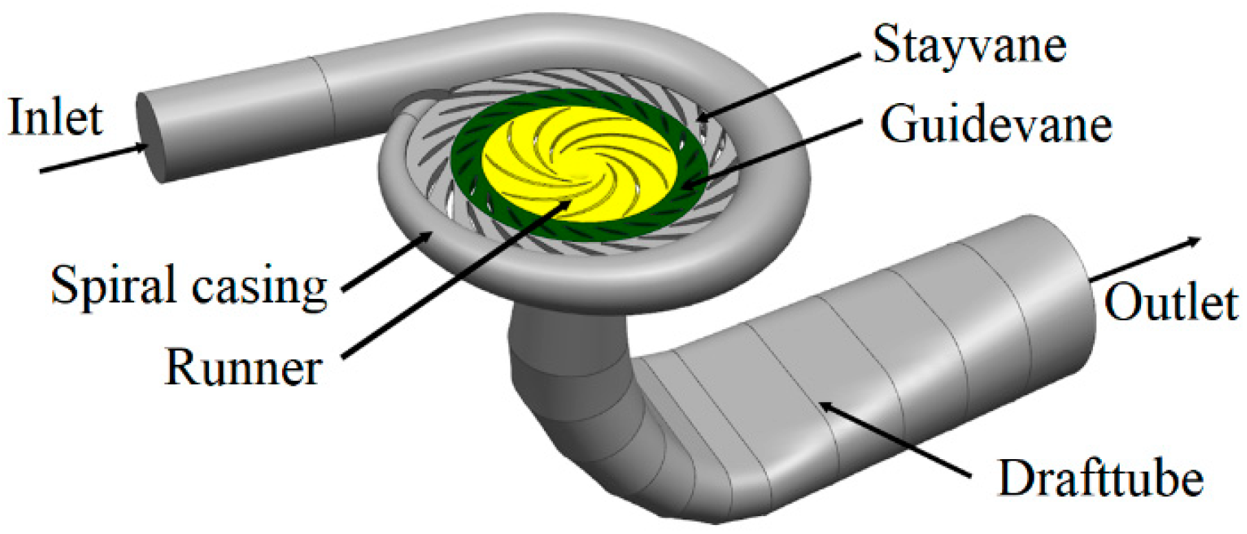
Figure 1. Pump-turbine.
Machines 10 00143 g001
Figure 2. Grid of model pump-turbine: (a) grid of spiral casing; (b) grid of draft tube; (c) grid of vanes; (d) grid of runner.
Machines 10 00143 g002
Figure 3. Position of pressure pulsation monitoring points. (a) Vaneless space, (b) Vaneless space axial, (c) Runner channel, (d) Spiral casing, (e) Spiral casing, (f) Draft tube.
Machines 10 00143 g003
Figure 4. Prototype test of time-domain of pressure pulsation in vaneless space.
Machines 10 00143 g004
Figure 5. Prototype test of frequency-domain of pressure pulsation in vaneless space.
Machines 10 00143 g005
Figure 6. Time-domain and frequency-domain of pressure pulsation in vaneless space at monitor VL6 (PINCOM and PCOM are the operating points in Table 3). (a) PINCOM, (b) PCOM.
Machines 10 00143 g006
Figure 7. Distribution of relative velocity at different operating points of 50% load. (a) Speed decomposition, (b) Relative velocity component distribution.
Machines 10 00143 g007
Figure 8. Relative amplitude of pressure pulsation in vaneless space. (a) Prototype pump-turbine, (b) Model pump-turbine.
Machines 10 00143 g008
Figure 9. Time and frequency characteristics of pressure pulsation at monitor VL6. (a) Prototype pressure pulsation time-domain diagram, (b) Prototype pressure pulsation frequency-domain diagram, (c) Model pressure pulsation time-domain diagram, (d) Model pressure pulsation frequency-domain diagram.
Machines 10 00143 g009aMachines 10 00143 g009b
Figure 10. Schematic diagram of test bench.
Machines 10 00143 g010
Figure 11. Streamline of vaneless space under different conditions. (a) OP1, (b) OP2, (c) OP3, (d) OP4, (e) OP5, (f) OP6, (g) OP7, (h) OP8, (i) OP9.
Machines 10 00143 g011
Figure 12. Streamline of vaneless space at different times at OP1. (a) T1, (b) T2, (c) T3, (d) T4, (e) T5, (f) T6.
Machines 10 00143 g012aMachines 10 00143 g012b
Figure 13. Streamline of vaneless space at different times at OP2. (a) T1, (b) T2, (c) T3, (d) T4, (e) T5, (f) T6.
Machines 10 00143 g013
Figure 14. Streamline of vaneless space at different times at OP3. (a) T1, (b) T2, (c) T3, (d) T4, (e) T5, (f) T6.
Machines 10 00143 g014
Figure 15. Relative pressure pulsation amplitude in all fluid channels. (a) Prototype pump-turbine, (b) Model pump-turbine.
Machines 10 00143 g015
Figure 16. Time domain of pressure pulsation in prototype and model pump-turbine. (a) Prototype pump-turbine VO1, (b) Model pump-turbine VO1, (c) Prototype pump-turbine ST2, (d) Model pump-turbine ST2, (e) Prototype pump-turbine GV2, (f) Model pump-turbine GV2, (g) Prototype pump-turbine RV2, (h) Model pump-turbine RV2, (i) Prototype pump-turbine DT1, (j) Model pump-turbine DT1.
Machines 10 00143 g016aMachines 10 00143 g016b
Figure 17. Time domain of pressure pulsation of the prototype and model pump-turbine. (a) PINCOM, (b) PCOM, (c) MINCOM, (d) MCOM.
Machines 10 00143 g017
Table 1. Basic geometric parameters of model and prototype.
ParameterModel ValuePrototype Value
Rated hydraulic head Hr (m)59.8635
Runner inlet diameter D1 (mm)5564448
Runner outlet diameter D2 (mm)2502000
Guide vane height b (mm)38.258306.064
Number of runner blades Zr99
Number of guide vanes Zg2222
Table 2. Number of grids and nodes.
PartGrid CellsNodes
Spiral casing1,052,6851,005,387
Stay vane1,072,038987,630
Guide vane1,384,5041,282,424
Runner1,579,3561,486,674
Draft tube547,189529,856
Total5,635,7725,291,971
Table 3. Operating points in CFD Simulation.
TypeOperating PointCompressibilityQ11/(L/s)n11/(r/min)H/mn/(r/min)Add
PrototypePINCOMIncompressible727.15045.520635488.79Rated operating point
PCOMCompressible
ModelMINCOMIncompressible59.81199.919
MCOMCompressible
Table 4. Technical index of PIV test system.
ParameterValue
Speed measurement range/m/s0~1000
Speed measurement accuracy/%≤1
Measured area/mm2≥900 × 1000
Overall operating frequency/Hz≤15
Bits16
Table 5. Test bed parameters.
ParameterValue
Test bench numberDF-150
Maximum test flow/m31.5
Maximum test head/m150
Maximum test speed/(r/min)2500
Diameter of model runner/mm250–500
Maximum power of dynamometer/kW500
Rated power of pump motor/kW2 × 850
Tail water pressure/kPa−85~+250
Uncertainty of efficiency measurement≤±0.25%
Test bed model typeCounterattack hydraulic machinery
Table 6. Table of working points.
Operating PointOpeningQ11/(L/s)n11/(r/min)n/(r/min)Load Range
OP1352.54337.0731141.87450% load
OP2343.13638.1021174.798
OP3331.11638.7201194.869
OP413°467.64237.1011144.78575% load
OP5458.51938.1031176.840
OP6451.72238.7271196.841
OP717°588.95437.0611143.869100% load
OP8579.85038.1471178.841
OP9574.44038.7941199.916
Publisher’s Note: MDPI stays neutral with regard to jurisdictional claims in published maps and institutional affiliations.