1. Introduction
The task of linkage synthesis is to determine the link dimension to form the linkage that achieve the specified task positions. According to the past literature [
1,
2], linkage synthesis can be divided into three task specifications, namely, motion generation, function generation, and path generation. Generally, the methods of linkage synthesis include analytical method and optimization method. Analytical method is to derive the synthesis constraint equations and solve it to obtain the configuration of the linkage. McCarthy et al. [
1], Freudenstein [
3], and Wampler et al. [
4] derived the constraint equations of four-bar linkages for motion generation, function generation, and path generation, respectively; additionally, see [
5,
6,
7]. Plecnik et al. derived the constraint equations of six-bar linkage for motion generation [
8], function generation [
9], and path generation [
10]. The advantage of analytical method is that all configurations of the linkage can be obtained by solving the constraint equations. The shortcoming is that it is difficult to solve the highly nonlinear polynomial equations. The optimization method is also a useful tool for linkage synthesis. The motion generation [
11], path generation [
12,
13], and hybrid task generation [
14] are studied by using different optimization algorithms. The advantage of the optimization method is that we do not need to formulate the constraint equations and it is easy to perform, but it is difficult to find the optimal configuration when the optimization variables are too many.
Many researchers have investigated the consideration of other performances during the intital stage of linkage design. Kiper et al. [
15] studied the mixed problem of correlation of crank angles and dead-center design with function generation of planar four-bar linkage. Zhang et al. [
16] presented a method to analyze the time-dependent kinematic reliability of four-bar linkage during the stage of function generation. Erkaya et al. [
17] used neural–genetic optimization approach to design four-bar linkage for path generation simultaneous considering the joints clearance. EI-Shakery et al. [
18] presented a method to optimally synthesize links’ lengths of four-bar linkage to achieve targeted transmission angle deviations. Daniali [
19] proposed a design method to synthesize the path generation of four-bar linkage considering the joint clearance, and controlled the unwanted degrees of freedom by revising the mass distributions of the moving links. Bai [
20] used optimization method to minimize the maximum absolute acceleration peaks of the mechanism through linkage dimension synthesis. In this paper, we present a novel design framework to synthesize the four-bar linkage for motion generation considering clearance joints and dynamics performance. Differently from the methods in the previous literature, the proposed design framework combines the analytical method for linkage synthesis and the optimization method for dynamics to obtain the optimal configuration of the linkage that completes the specified task positions with high motion accuracy and low wear extent of clearance joint.
Due to manufacturing error, the clearance is inevitable in the revolute joint of the linkage. The nonlinear impact between the journal and the bearing will reduce the operation accuracy and reliability of a mechanical system [
21,
22,
23]. Dynamic modeling of the mechanism systems has been identified as an important tool in the analysis, design, optimization, and simulation. To establish the dynamic model and achieve the dynamics analysis of mechanical systems with clearance joints, scholars have presented many novel and effective methods, such as [
24,
25,
26,
27,
28]. Based on the dynamic models, scholars around the world have carried out many significant research works about the dynamic response, performance evaluation, and optimization of mechanical systems with clearance joints. Flores [
29] employed the dynamic model to study the effects of clearance size, driving velocity, and number of clearance joints on the dynamic response of mechanical systems, and evaluated the total computation time consumed in each simulation. Xiang et al. [
30] employed the fractal method to evaluate the complexity of dynamic response of mechanisms with clearance joints. Li et al. [
31] used the Monte Carlo method to analyze the kinematic accuracy and dynamic performance of a space deployable mechanism with joint clearance while considering parameter uncertainty. Considering clearance joints and uncertainties, Xiang et al. [
32] proposed an analysis method for dynamic response and parameter sensitivity of mechanical systems based on Chebyshev polynomials method. Lai et al. [
33] presented a prediction method of wear extent for clearance joints, and the method was validated by using experimental data. Wang et al. [
34] studied the dynamic performance of a spatial parallel mechanism by dynamic simulation. However, the above research works have not improved the dynamic performance of the mechanical systems from the perspective of mechanism synthesis.
In this paper, the aim of the proposed design framework was to improve the dynamics performance during the stage of linkage synthesis. In the design framework, the constraint model of motion generation and the dynamics model of four-bar linkage were established, respectively. The coordinates of two fixed joints are the parameters to improve the dynamics performance of the linkage and were selected as the optimization variables, and the coordinates of two moving joints were to satisfy the kinematics requirements and are obtained by solving constraint equations of motion generation. Through optimization calculation, we can obtain the optimal configuration of the four-bar linkage that achieves specified task positions with high motion accuracy and low wear extent of clearance joint. In what follows, we demonstrate the performance of the design framework.
2. The Synthesis of Four-Bar Linkage for Motion Generation
Motion generation of four-bar linkage is widely used in engineering, for example, in the pick and place mechanism, car steering, walking robot, etc. The goal of motion generation is to design four-bar linkages whose coupler link can pass the specified locations and orientations. For convenience, here, the above locations and orientations are called task positions. In this section, we use analytical method to derive the constraint equations of four-bar linkage for motion generation, and propose a strategy to check the kinematics performance of the obtained linkage.
2.1. Constraint Equation of Four-Bar Linkage for Motion Generation
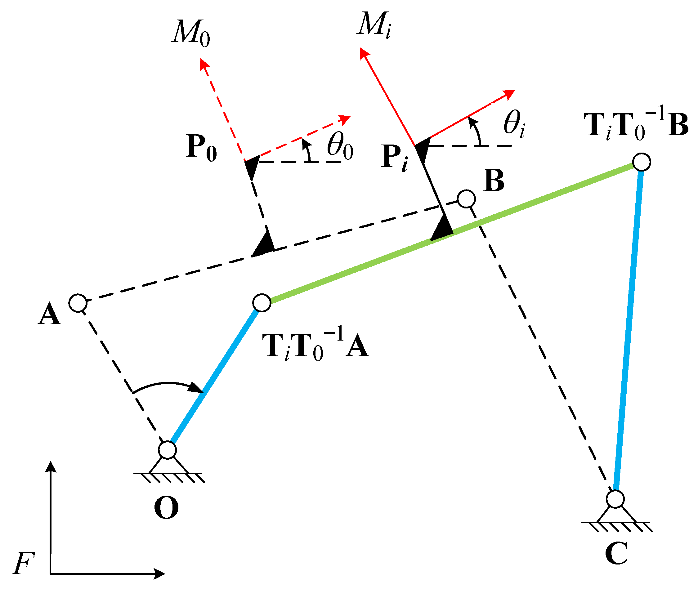
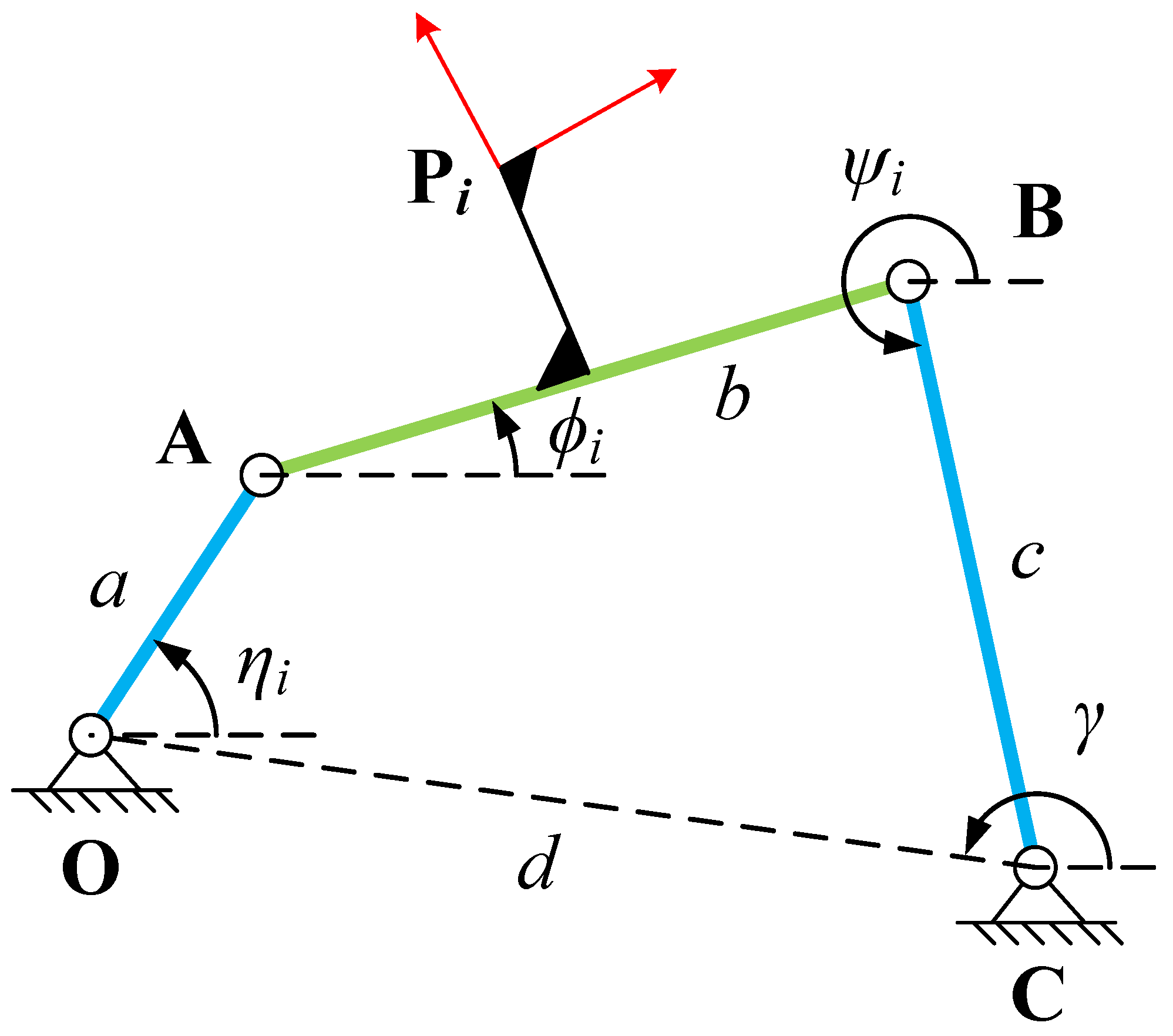
Figure 1 shows the representation form of four-bar linkage for motion generation. Here, the task positions are
and
,
, where
m denotes the maximum number of task positions that the linkage can arrive. The task positions are specified by designer. The task is to determine the coordinates of four joints (
,
,
and
) to form a four-bar linkage that can arrive the specified task positions.
In
Figure 1, the four-bar linkage
is moving from task position
to
. Besides,
is the crank,
is the rocker, and
is the coupler link. The moving frame
is fixed on the coupler link, and its origin is at point
. The angle between the moving frame
and the initial frame
F is the specified orientation angle
. The homogeneous transformations from the moving frame
to the initial frame
F can be given by the following:
where
denotes the coordinate of point
. Likewise, points
,
,
, and
can be denoted as
,
,
, and
in the initial frame when the four-bar linkage is at the first position
.
At first task position
, we have the following constraint equation:
where
a and
c are constants and denote the lengths of links
and
, respectively.
When the four-bar linkage arrives at the task position,
, the constraint equation can be expressed as follows:
Then, we let Equation (
3) subtract Equation (
2) to eliminate
a and
c and obtain the constraint equations of four-bar linkage for motion generation, which are given as follows:
In Equation (
4), there are eight unknowns, which are the coordinates of four joints of the linkage. So the maximum number of task positions that the four-bar linkage can arrive is five. However, most cases in engineering are that the needed task positions is less than five [
35]. This will allow some unknowns to be not constrained, and that can be the parameters for considering dynamics performance of the linkage.
2.2. Performance Verification of the Crank–Rocker Mechanism
After solving the synthesis constraint equations, the kinematics performance of obtained linkages need to be checked to obtained the non-defect linkages that can move in an orderly and smooth manner during the whole movement [
36,
37,
38]. In this section, we mainly check whether the obtained linkages have the Grashof’s defect, the order defect, the circuit defect, and the branch defect.
(1) Checking Grashof’s defect:
Generally, we hope that the four-bar linkage has a crank that can fully rotate, so that the linkage can be driven by a continuously rotating motor. In this paper, we take the crank–rocker four-bar mechanism as the research object. All links lengths of the four-bar linkage can be obtained after the synthesis constraint equations are solved. As shown in
Figure 2,
a,
b,
c, and
d denote the lengths of link
,
,
, and
, respectively.
For the crank–rocker mechanism, the link is the input link and can rotate fully 360 degrees. According to Grashof’s rule, a must be the length of the shortest link. Besides, let . The linkage should also meet the constraint that the sum of a and is less than the sum of the remaining two links lengths.
(2) Checking order defect:
When the input link rotates in one direction (clockwise or anticlockwise), the linkage arrives the task positions in an unspecified order, which means that the linkage has the order defect. Here, we show a simple method to check the order defect. In
Figure 2,
,
,
,
denote the angles of link
,
,
, and
, relative to
x-axis of the initial frame when the linkage arrives at task position
, and they can be determined after the candidate linkage are obtained. Then, we define the following:
where operator “×” denotes the cross product symbol,
[•] represents sign function, and
denotes the third component of vector
. If
remains the same sign, it indicates that the linkage can orderly arrive the task positions when the crank rotates in clockwise or anticlockwise.
(3) Checking circuit defect and branch defect:
The linkage needs to be reassembled to move between two positions, which is called the circuit defect linkage. The linkage needs to pass through a singular configuration but needs not to be reassembled, which is called the branch defect linkage. To check the circuit defect and the branch defect, the motion state of each link should be identified when the input angle changes in the range of 360 degrees. So we establish the kinematic constraint equations, which are given as follows:
In Equation (
6),
is input variable,
is constant, and
and
are unknowns that should be solved. Because of the property of cos(•) function, there are two sets of solutions of
and
for a specified value of
. Here, we divide
into
s parts in 360 degrees, which include
m values of input angles for the linkage at
m task positions. By substituting these
s input angles into Equation (
6) and solving them, we can obtain the following:
In Equation (
7), the index of each set of solution is disordered, this means that we do not know the linkage is at position
or
when the linkage moves from
to
. Here, we use Newton iteration method to sort the solutions into two branches. The Newton iteration equations of the linkage can be written as follows:
where
is the Jacobian matrix,
Based on Equation (
8), the positions
and
can be obtained from corresponding positions
and
when the linkage moves from
to
. Do
times for the above process, the solutions can be sorted into two separated branches, which can be denoted as follows:
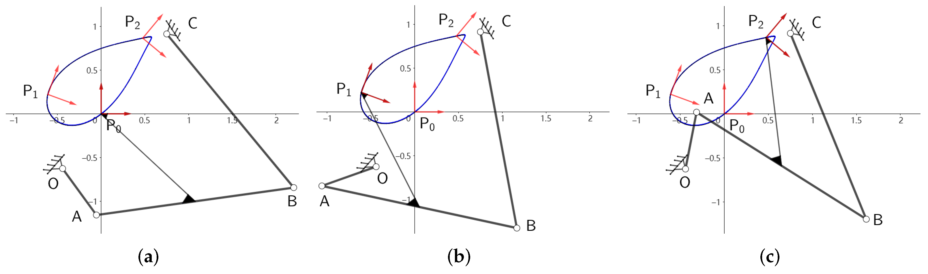
Then we test if
m specified task positions are always on one of the two sorted branches. For example,
Figure 3 shows that
and
of all specified task positions are always on branch 1. If all specified task positions are on the same branch, we test the Jacobian determinants of the branch that all task positions are on. If the signs of the Jacobian determinants remain unchanged, the candidate linkage are non-defect linkage.
If the linkage has no Grashof’s defect, order defect, circuit defect and branch defect, the linkage can be selected as the desired crank–rocker mechanism that can pass through m task positions in an orderly and smooth manner.
3. Dynamics Modeling for Four-Bar Linkage with Revolute Clearance Joints
Generally, the links of four-bar linkage are interconnected by four revolute joints. For an ideal revolute joint, the center of journal always coincides with that of bearing in the whole motion process. In fact, the joint clearance is inevitable. When the joint clearance is considered in a revolute joint, it is obvious that the journal can move freely inside the bearing, and the nonlinear impact will occur between the journal and the bearing. Further, the above impact will exacerbate the wear between the journal and the bearing. Therefore, the existence of joint clearance will reduce the operation accuracy and service life of four-bar linkage. To study the dynamics characteristics of four-bar linkage with revolute clearance joints, we will establish its dynamics model in this section.
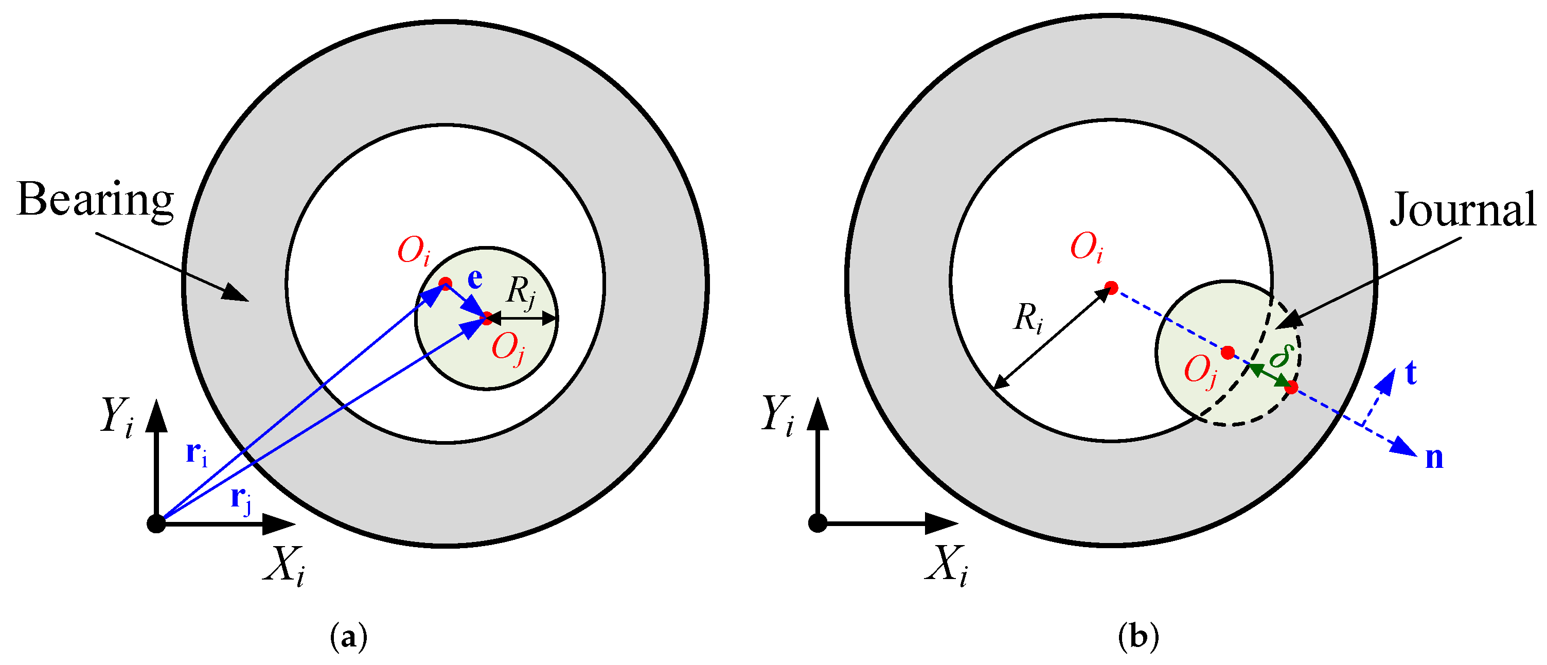
Figure 4 shows the configuration of a revolute joint with clearance.
Specifically, the separation status refers to the state where the journal is not in contact with the bearing. The contact status refers to the state where the journal is in contact with the bearing. Here, the bearing is fixed on the body
i, and the journal is fixed on the body
j. In addition,
denotes the local coordinate system fixed on the body
i. In this paper, the bearing and journal are both regarded as rigid bodies. Besides,
denotes the bearing center, and
denotes the bearing inside radius.
denotes the journal center, and
denotes the journal radius. Then, we let
denote the position vector of
, relative to the origin of
,
denote the position vector of
relative to the origin of
, and
denote the position vector of
relative to
. According to the geometric relationship, we obtain the following:
We let
denote the radial clearance. According to the geometric relationship, we obtain the following:
Further, the penetration depth between the journal and the bearing can be expressed as follows:
When
is not equal to 0, the unit vector in the direction of
is denoted as
, and we obtain the following:
The orthogonal unit vector of
is denoted as
, and we obtain it by rotating
anticlockwise by 90. When the journal is in contact with the bearing, the position vector of contact point relative to
is denoted as
, and its expression is the following:
The normal velocity of the contact point is denoted as
, and the tangential velocity of the contact point is denoted as
. According to the motion relationship,
and
can be expressed as follows:
When the journal is in contact with the bearing, the contact force can be divided into the normal force and the tangential force. The direction of the normal force is along the direction of
, and the direction of the tangential force is along the direction of
. In this paper, the normal force is described by using the Lankarani–Nikravesh contact force model [
39], and the tangential force is described by using the modified Coulomb friction model [
22]. The above two models are widely used for the dynamics modeling of mechanical systems with clearance joints. According to Reference [
39], the normal force is expressed as follows:
In Equation (
17),
n denotes the nonlinear exponent, and it equals 1.5 here. Besides,
K denotes the stiffness coefficient, and its expression is as follows:
where
and
denote the material parameters. In this paper, the expressions of
and
are as follows:
where
E denotes the Young’s modulus and
denotes the Possion’s ratio. In Equation (
17),
D denotes the damping coefficient, and its expression is as follows:
where
and
denote the restitution coefficient and the initial impact velocity, respectively. According to Reference [
22], the tangential force is expressed as follows:
where
denotes the friction coefficient, and we obtain the following:
In Equation (
22),
denotes the static friction coefficient,
denotes the sliding friction coefficient,
denotes the stick–slip switch velocity, and
denotes the static–sliding switch velocity.
In this research work, the dynamic modeling method was not our research focus. For convenience, we employ the MSC.ADAMS software to establish the dynamics model of four-bar linkage with clearance joints. In MSC.ADAMS software, the dynamics equations of multibody system are established by using the Lagrange equation, and the specific principle has been presented in reference [
40]. At present, MSC.ADAMS has been widely used for dynamics simulation of mechanical systems with clearance joints. Through the secondary development of MSC.ADAMS software, the contact force model of clearance joint is established by using Equations (
11) and (
22). Besides, the dynamics model of four-bar linkage is solved by using the wstiff-SI2 integrator algorithm, whose principle has been specifically introduced in Reference [
41].
4. Design Framework for Motion Generation of Four-Bar Linkage
Traditionally, the synthesis of four-bar linkage for motion generation can only let the obtained mechanism pass through the specific task positions, and its dynamics performance is generally not concerned. As mentioned above, if the number of task positions is less five, parts of joints coordinates can be used as the design parameters for considering dynamics performance of the linkage. Here, the dynamics performance refers to the performance that should be evaluated by dynamics analysis. Because of the inevitable joint clearance, the actual operating state of the four-bar linkage will be different from the ideal one. Therefore, when carrying out the synthesis of four-bar linkage for motion generation, we need to consider the dynamics performance, which will make the result have more practical engineering significance. After the dynamics model of four-bar linkage is established, we can use it to evaluate the dynamics performance. Next, combining the dynamics model and the synthesis method of
Section 2, we will propose a design framework for motion generation of four-bar linkage considering clearance joints and dynamics performance.
4.1. Dynamics Performance Evaluation
In this paper, the dynamics performance of four-bar linkage includes the operation accuracy and the wear extent of clearance joint, which can be analyzed by dynamics simulation. According to
Section 2, the output link should pass through several specific positions during the motion process. If the four-bar linkage operates continuously, the output link needs to pass through the specific position at the specific time. It should be noticed that the output link also needs to follow the specific orientation when passing through the specific position. Therefore, the operation accuracy can be subdivided into the position accuracy and the orientation accuracy. The evaluation parameter of position accuracy is expressed as follows:
where
denotes the actual position that the output link passes through at the ith specific time, and
denotes the corresponding ideal position.
is obtained by dynamics simulation. Besides, the evaluation parameter of orientation accuracy is expressed as follows:
where
denotes the actual orientation of output link at the
ith specific time, and
denotes the corresponding ideal orientation.
is obtained by dynamics simulation. The smaller the
and
, the higher the operation accuracy of four-bar linkage.
In fact, the wear extent of clearance joint directly determines the service life of four-bar linkage. In this paper, we employ the Archard model to describe the wear extent of clearance joint [
42]. The Archard model can be expressed as follows:
where
k and
H denote the material related coefficients,
denotes the relative slip distance between the journal and the bearing, and
V denotes the wear volume. During the dynamics simulation,
is difficult to obtain directly. After differentiating Equation (
25) relative to time, we can obtain the following:
Then, we obtain the following:
Generally,
k and
H are constant, so the evaluation parameter of wear extent of clearance joint can be expressed as follows:
In this paper, we will set a shorter operating time span for four-bar linkage, so the effect of wear on and can be neglected. The smaller the , the lighter the wear extent of clearance joint.
4.2. The Novel Design Framework
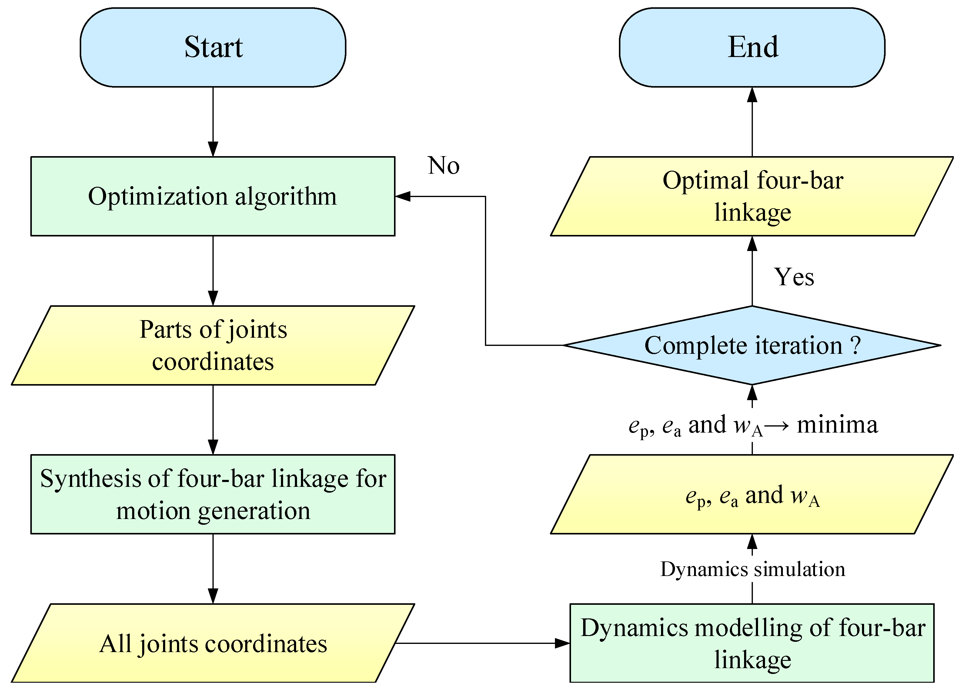
In this section, we will propose a design framework for motion generation of four-bar linkage considering clearance joints and dynamics performance. The novel design framework covers the mechanism synthesis method, dynamics simulation method, and multi-objective optimization method, and its flowchart is shown in
Figure 5.
First, the optimization algorithm generates parts of joints coordinates of four-bar linkage based on the number of task positions. Then, these coordinates are used for carrying out the synthesis of four-bar linkage for motion generation, and all joints coordinates are obtained. Using the above joints coordinates, we can establish the dynamics model of four-bar linkage. After dynamics simulation, , and can be calculated. Here the optimization objective is to minimize , and simultaneously. When the optimization iteration calculation is completed, we can obtain the Pareto optimal set of the joints coordinates for optimization variables. Meanwhile, the optimal joints coordinates of four-bar linkage are also obtained. Finally, we can determine the optimal four-bar linkage.
In this paper, we employ the non-dominated sorting genetic Algorithm II (NSGA-II) to solve the above multi-objective optimization problem. The principle of NSGA-II has been specifically introduced in reference [
43]. Of course, the usage of NSGA-II is just an example, and other effective algorithms can also be used for solving the above multi-objective optimization problem. To sum up, the optimization mathematical model is expressed as follows:
where
and
denote the frame coordinates of four-bar linkage,
,
,
, and
denote the lower limits of
,
,
, and
, respectively, and
,
,
, and
denote the upper limits of
,
,
, and
, respectively. It should be noticed that all objective functions are closely related to the clearance joints. If the joint clearance does not exist, all objective functions will always equal 0. Therefore, the joint clearance must have an obvious effect on the optimization results. In order to reduce the computational complexity, we only consider only one clearance joint in the following research works, which is same as reference [
20]. Of course, the proposed method has certain generality, and designers can carry out the optimization calculation considering the multiple clearance joints.
5. Case Study
In this section, we will give an example to demonstrate the design framework proposed by us. For the motion generation of four-bar linkage, we let the output link pass through three specific task positions during the motion process, and select two fixed joints coordinates as optimization variables for considering dynamics performance. Besides, the output link also needs to follow the specific orientation when passing through the specific position. The targeted positions and orientations are shown in
Table 1.
Here, we set the time when the output link is at position 1 as the initial time. Besides, we let the output link pass through positions 1–3 in turn.
In the dynamics model, the four-bar linkage consists of three ideal revolute joints, one between the crank and the frame, one between the crank and the output link, and the other between the rocker and the frame, and a revolute clearance joint between the output link and the rocker. The crank is driven by using the constant angular velocity
. The mass parameters values of the four-bar linkage are shown in
Table 2.
In addition, the related parameters values of contact force model are shown in
Table 3.
At the initial time, we let the centers of the journal and bearing be coincident. Besides, the total simulation time is set to 7.2 s, which means that the crank will rotate 2 turns. Therefore, in fact, there will be six targeted positions and orientations given by the following:
During the dynamics simulation, the related parameters values of wstiff-SI2 integrator algorithm are shown in
Table 4.
In this paper, the parameter configuration of NSGA-II is shown in
Table 5.
Besides, the limits of optimization design variables are shown in
Table 6.
After optimization calculation, we obtain the Pareto optimal set shown in
Table 7.
Here, we independently execute the above optimization three times, and the obtained Pareto optimal solutions are relatively steady, which means that the parameter configuration of NSGA-II is rational. In addition, it takes 12 h to complete a single optimization calculation.
6. Results and Discussions
Table 7 illustrates that the three optimization objectives,
,
and
, are contradictory, which means they can not reach the minimum simultaneously in a configuration. So, we select three solutions from the Pareto optimal set to carry out the further research. The three solutions have the minimum
, the minimum
, and the minimum
, which are No. 1, No. 9, and No. 8, respectively. According to the synthesis constraint, the coordinates of all joints for three selected configurations can be obtained and are shown in
Table 8.
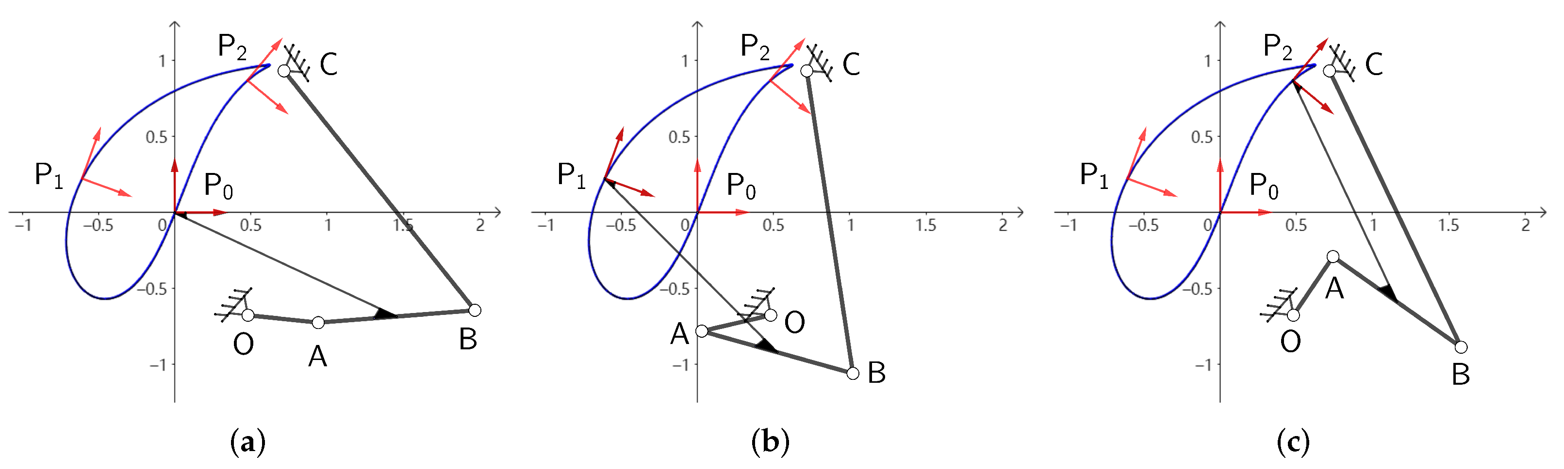
The specific configurations can be determined based on the joints coordinates. For the three configurations, we carry out the kinematics simulation, and obtain the motion processes of four-bar linkages.
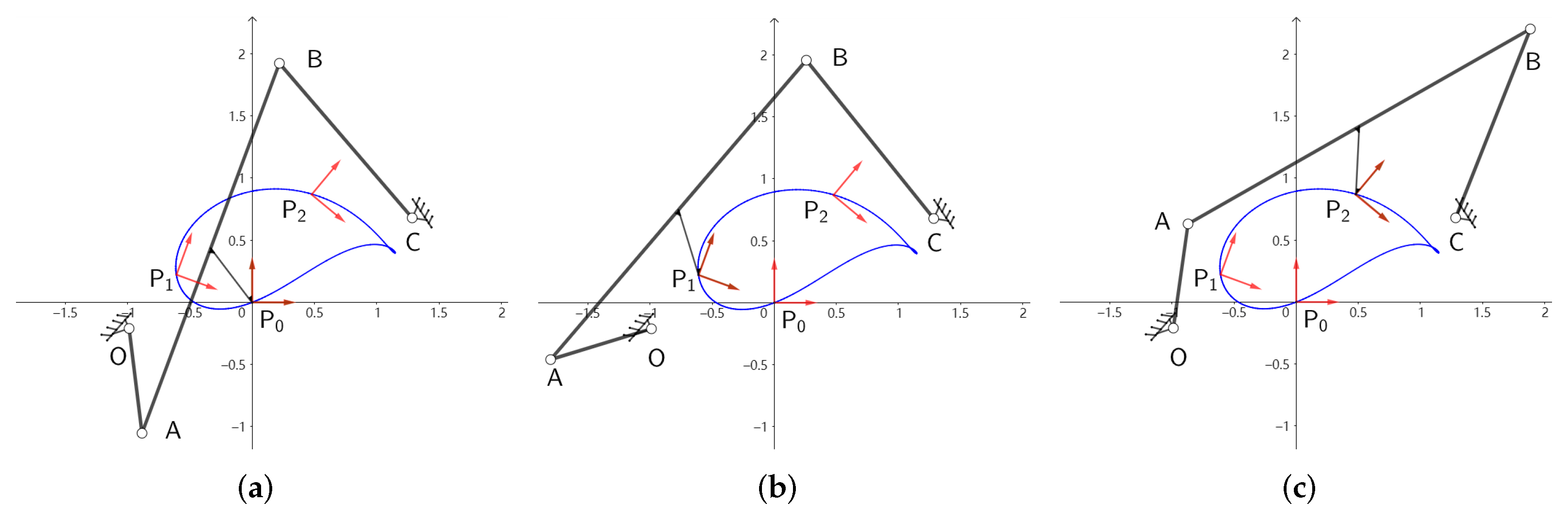
Figure 6 shows the motion process of the four-bar linkage for the configuration of the minimum
,
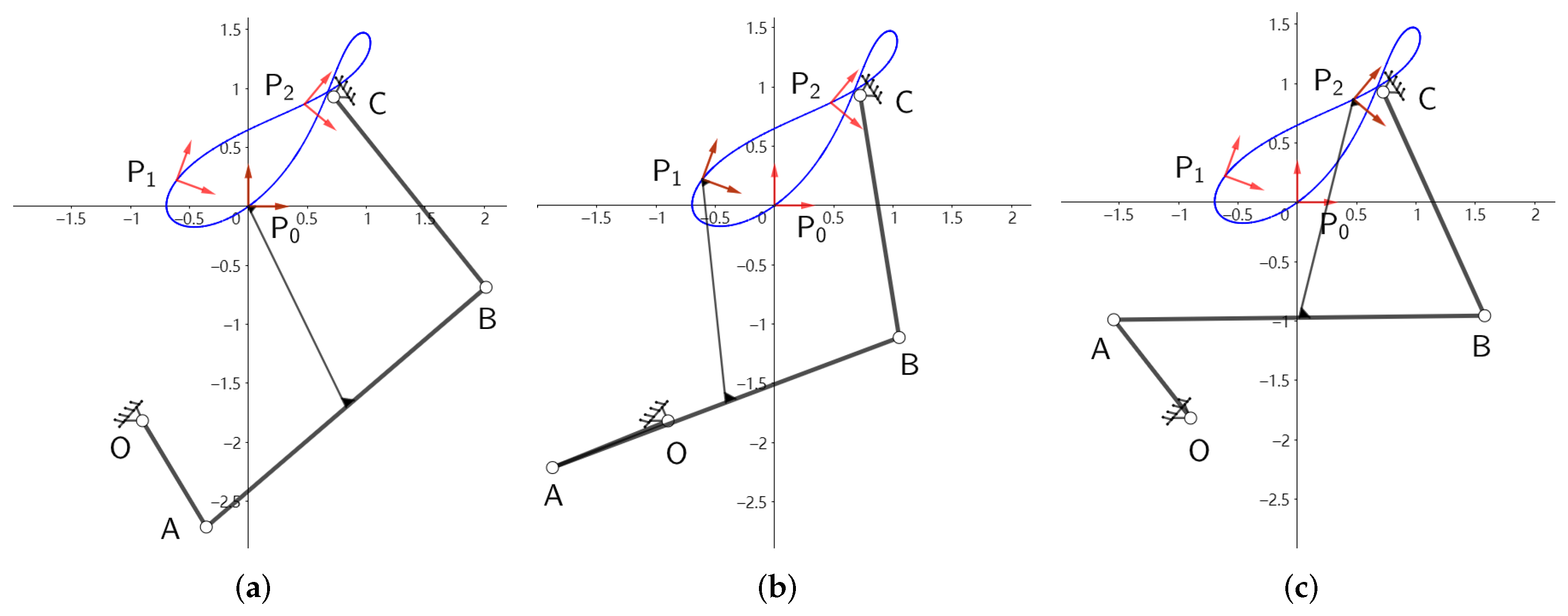
Figure 7 shows the motion process of the four-bar linkage for the configuration of the minimum
and
Figure 8 shows the motion process of the four-bar linkage for the configuration of the minimum
. Through the motion process, the four-bar linkages for the three configurations can pass through the task positions in an orderly and smooth manner.
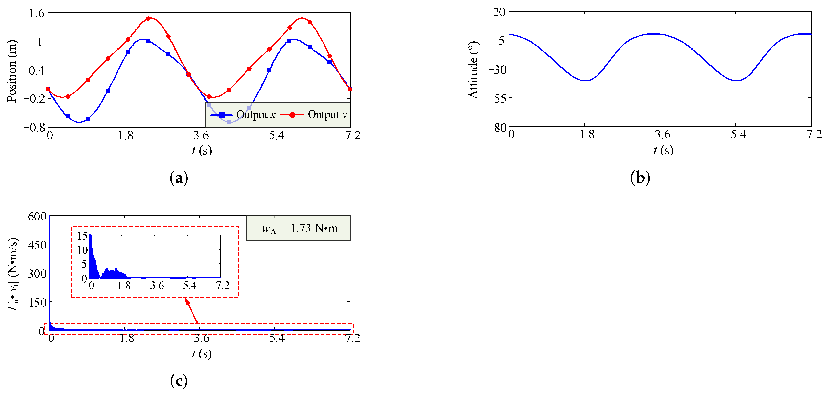
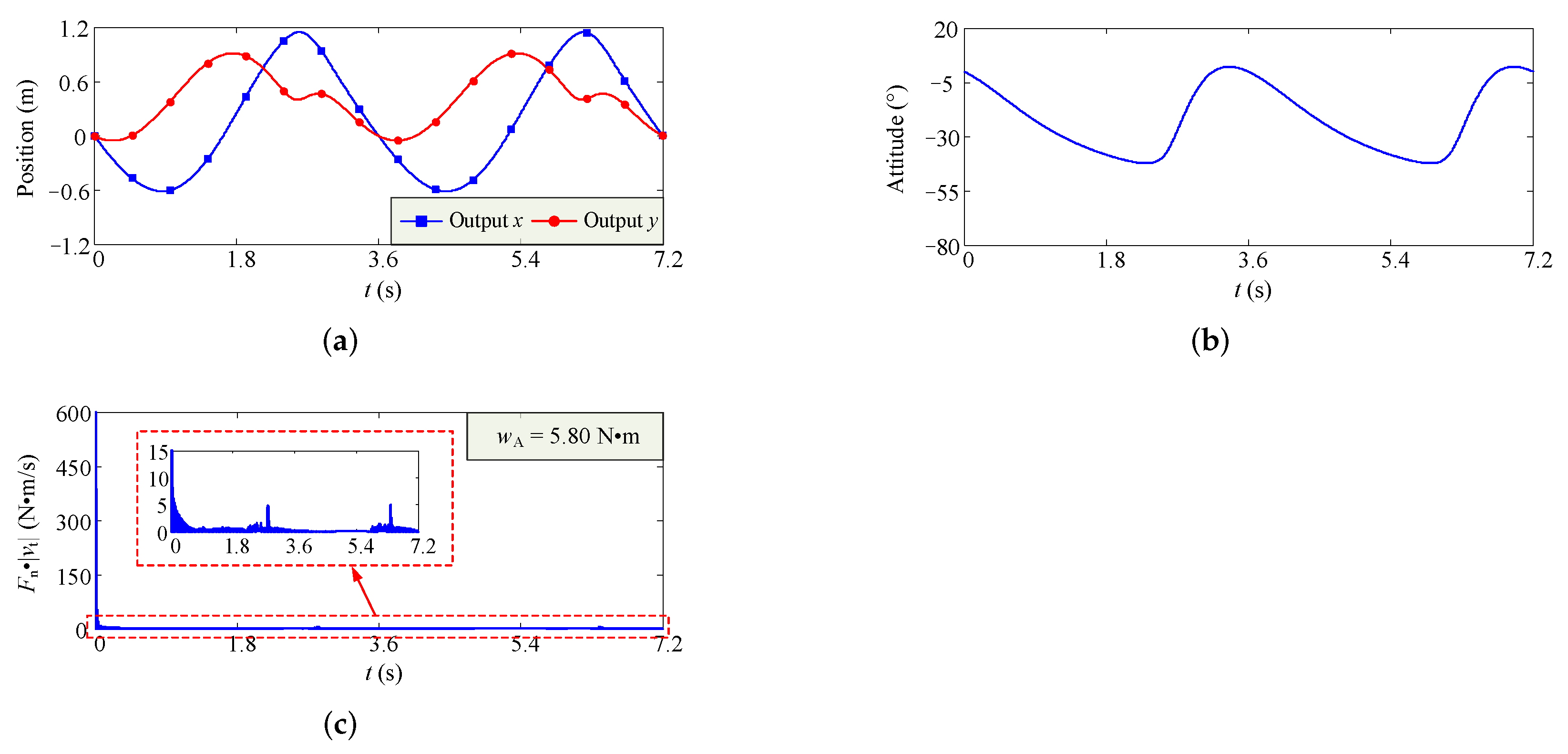
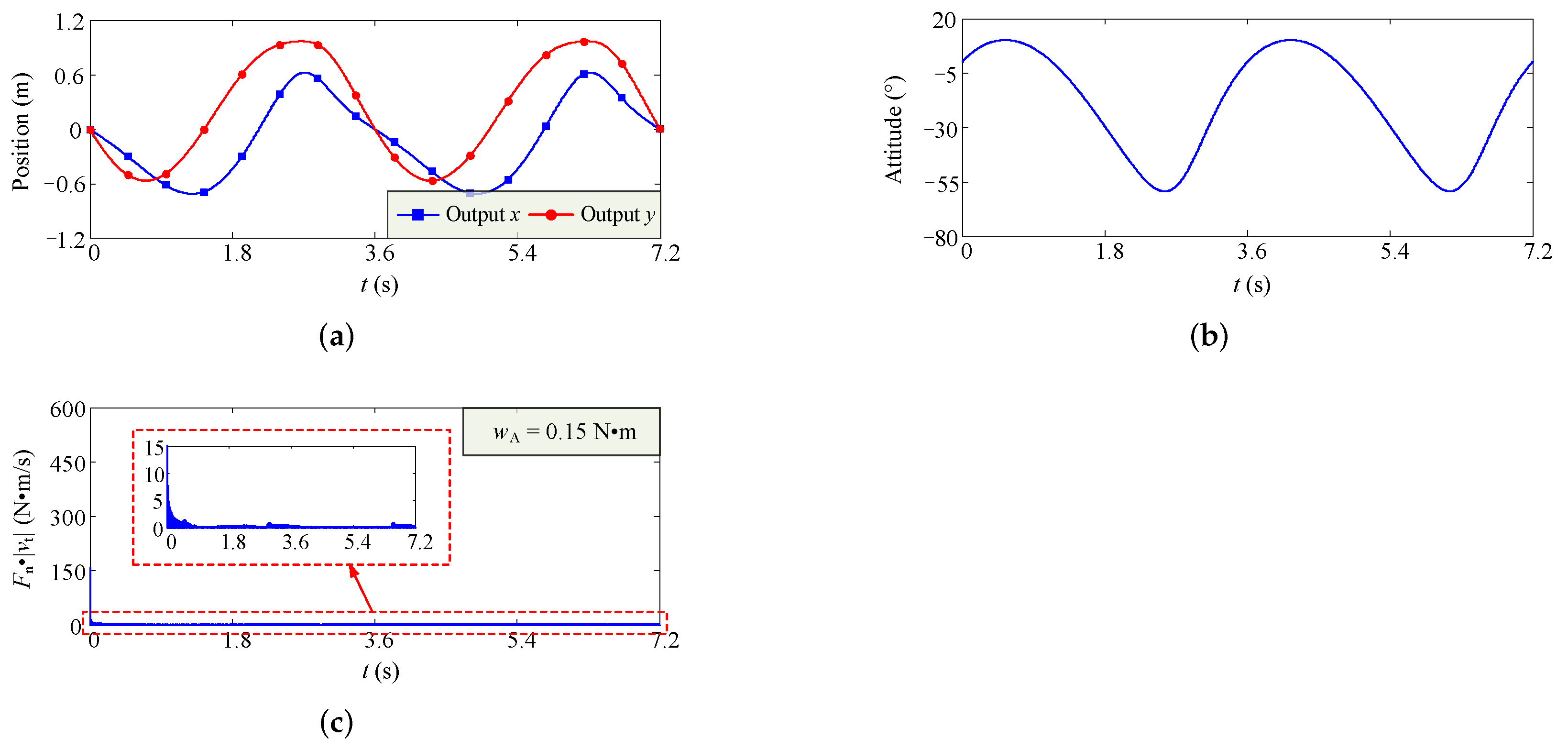
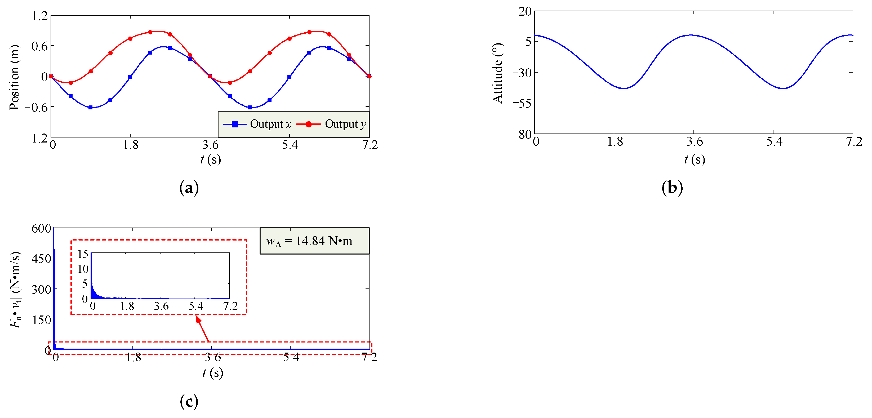
In an actual engineering application, we can manufacture the output part of the output link by using the materials with lower quality, such as carbon fiber. Therefore, the effect of the output part on the inertia properties of the whole link can be neglected. Then, for three configurations, we carry out the dynamics simulation, and obtain the variation curves of output position, output orientation, and
, which are shown in
Figure 9,
Figure 10 and
Figure 11.
Figure 9,
Figure 10 and
Figure 11. show that the motion of four-bar linkage is relatively stable, and the wear of clearance joint is more severe when the four-bar linkage begins to move.
The above analysis results also show that the values of and are small, which means that the operation accuracy of the mechanism is relatively easy to guarantee. In actual engineering application, the wear extent of clearance joint directly determines the service life of four-bar linkage. In view of this, we select the solution with the minimum from the Pareto optimal set as the final optimal solution.
To validate the proposed design framework, we compare it with the traditional linkage synthesis method [
44]. In traditional linkage synthesis method, this is the motion generation for three task positions. The common strategy is that giving the specified values for unconstrained parameters or random selecting values in the corresponding ranges. Here, we randomly select 1000 groups of values for the parameters
,
,
, and
in their ranges, and select the non-defect configuration with minimum wear extent,
. The joints coordinates of selected four-bar linkage are shown in
Table 9. Furthermore,
Figure 12 shows the linkage can pass through the three task positions in an orderly and smooth manner. Then, for this configurations, we carry out the dynamics simulation, and obtain the variation curves of output position, output orientation and
, which are shown in
Figure 13. For this configuration, the wear extent
Nm, which is greater than the wear extent of the configuration obtained by the design framework. The above research works illustrate that the design framework is reliable and can be considered for engineering practice.


