Article

Design and Analysis of a Spherical Robot with Rolling and Jumping Modes for Deep Space Exploration

1
School of Mechatronical Engineering, Beijing Institute of Technology, Beijing 100081, China
2
Qian Xuesen Laboratory of Space Technology, China Academy of Space Technology, Beijing 100094, China
3
China Aerospace Science and Technology Corporation, Beijing 100048, China
4
College of Engineering, Peking University, Beijing 100871, China
*
Authors to whom correspondence should be addressed.
Machines 2022, 10(2), 126; https://doi.org/10.3390/machines10020126
Submission received: 12 January 2022 / Revised: 4 February 2022 / Accepted: 7 February 2022 / Published: 10 February 2022
(This article belongs to the Section Machine Design and Theory)

Abstract

:
Complex and unknown terrains in deep space exploration present great challenges to existing exploration robots. In this paper, a multi-mode motion spherical robot with flexible motion and strong environmental adaptability is presented. The spherical robot can roll and jump by swinging the pendulum and rotating the 2-DOF frame. The structure design of spherical robot is described, and the feasibility of multi-mode motion is analyzed by establishing dynamic model and testing robot prototype. In addition, the adaptability of the spherical robot motion mechanism in microgravity environment is preliminarily verified. The results of this analysis and test could be provided with reference for the future research of deep space exploration robots.

1. Introduction

In deep space exploration, large detectors with high functional density and complex structures, such as American Perseverance [1], China Zhurong [2] and so on, are usually used for exploration tasks. With the development of space technology, the future deep space exploration will no longer be satisfied with simple patrols and sampling tasks in a limited area. The detectors are expected to detect the unknown environment quickly and widely. Therefore, on the basis of the existing large detectors, it may be one of the effective schemes to carry several small detection robots with flexible movement and simple structures for the pre-detection of unknown areas [3,4].
At present, the small-scale detection robots developed by researchers are mainly wheeled or legged robots. However, the unstructured environment with many obstacles would easily cause the overturning and tumbling of these robots, further leading to the failure of the pre-detection task. Therefore, spherical robots with completely symmetrical geometry are the development trend of small detectors in the future. Aarne Halme et al. first started the research on spherical robot, developed a single-wheel-driven spherical motion machine and established dynamic model [5]. Ranjan Mukherjee et al. proposed a scheme to drive a spherical robot by changing the position of the center of mass to achieve all-round movement of the robot [6]. Paolo Fiorini et al. developed a spherical robot with jumping ability, which compressed energy storage through an internal transmission structure and guided springs to achieve intermittent jumping [7]. Zhao Bo et al. developed a spherical robot driven by a double pendulum, which can realize linear motion, circular motion, in-situ steering and jitter [8]. Vrunda Joshi et al. designed a spherical robot driven utilizing two internal rotors, which was based on the principle of conservation of angular momentum, as well as the Eulerian parameter of the unit quaternion was used to determine the orientation of the robot [9]. L. Ferriere et al. designed and developed a spherical robot driven by a combination of spherical wheel and universal wheel, which improved the bearing capacity and anti-bumping ability of the spherical robot [10]. Sung-Su Ahn et al. designed a spherical robot with the ability to change the direction of motion at rest, an orthogonal frame was used to achieve all-round ability to drive [11]. These spherical robots, driven in different ways, can only achieve a single motion mode such as rolling or jumping, which makes it difficult to cope with the complicated detection environment.
Therefore, researchers have attempted to design spherical robots with composite motion modes. Youngmin Kim et al. designed a spherical robot with the ability to roll and crawl, with retractable arms inside the left and right hemispheres, allowing the spherical robot to switch between rolling and crawling modes. The robot was hindered by the synchronous rotation of the two hemispheres, and the rolling mode followed the design of a traditional wheeled robot [12]. Rhodri Armour et al. designed the Jollbot with the ability to roll and jump. With a flexible metal semi-circular ring as the external skeleton, the robot compressed the skeleton to generate deformation to store energy and achieve jumping. But the hollow shell design would result in a small contact area with the ground and weak rolling ability [13].
In this paper, a concept of spherical robot with the ability of rolling and jumping motion mode is presented. Compared to spherical robots with a single motion mode [5,6,7,8,9,10,11], the spherical robot that we have designed combines rolling and jumping motion modes, thus allowing for a greater variety of movements. In contrast to other spherical robots with a composite motion mode [12,13], this spherical robot still places emphasis on the ability to roll as the main movement mode, which allows the spherical robot to move more efficiently. On flat ground, the spherical robot can roll quickly and steer flexibly, and can jump over obstacles when encountering obstacles or gullies. The structure of the spherical robot is designed and the motion characteristics are analyzed by establishing the dynamics model. On this basis, a spherical robot prototype with compound motion mode is developed, and the motion ability is tested and characterized.

2. Structure Design

In order to meet the requirements for batch transportation and handling of spherical robots, a robot with simple structures and lightweight is needed. A structure-function integrated design method is adopted to reduce the redundancy of components as much as possible based on realizing the rolling and jumping functions. The overall structure of the spherical robot consists of a spherical shell, rolling drive module and jumping drive module, as shown in Figure 1. The shell of the spherical robot is composed of two hemispheres, which are connected by flanges to form a closed sphere structure. The rolling drive module (Figure 1c) and the jumping drive module (Figure 1d) are placed inside the sphere shell to control the rolling and jumping of the spherical robot, where the jumping drive module is used as a pendulum in the rolling motion.
The rolling drive module is mainly composed of two frames and three motors, as shown in Figure 1c. The two DC geared motors are fixed to the two sides of the first frame, and the output shafts of the motors are fixed to the spherical shell through the flanges. By reversing the synchronous rotation of the two DC geared motors, the first frame rotates to achieve the forward/backward rolling motion of the spherical robot. The stepper motor is fixed to the second frame and the output shaft through the second frame and is fixed to the first frame. When the stepper motor works, the second frame rotates within a certain angle, so that the pendulum is biased towards the left or right, to achieve the left/right steering motion of the spherical robot.
The jumping ability of the spherical robot is realized by storing and releasing energy from the spring. The jumping drive module is mainly composed of a mechanism case at the upper part and two six-bar mechanisms at the lower part, as shown in Figure 1d. The six-bar mechanism suspends linear springs at the left and right diagonal positions. Inside the mechanism case, worm and worm motors, gear train, bars and pulleys with winding wires are assembled, as shown in Figure 2.
Driven by the worm gear motor, the gear train drives an incomplete gear to rotate. When gear 3 and gear 4 remain engaged, the rope twists as the gear rotates. The mechanism case moves down and the six-bar mechanism is compressed so that the spring can be stretched to complete the storage of elastic potential energy, as shown in State 1 in Figure 3. When the mechanism case descends to the bottom of the spherical robot, the worm motor is locked, and the limit state of spring tension is maintained by the self-locking of the worm structure. The linear force of the spring is converted into nonlinear force by the transmission characteristics of the six-bar mechanism, so as to reduce the friction loss between structures in the locked state [14], as shown in State 2 in Figure 3. When gear 3 drives the incomplete gear to the non-meshing position with gear 4, the rope relaxes. The elastic potential energy is released and converted into the kinetic energy of the mechanism case, and the mechanism case rapidly impacts the second frame, leading to the robot jumps under the action of inertia, as shown in state 3 in Figure 3. The second frame plays a limiting role in the movement of the mechanism case, facilitating secondary energy storage.
It is worth mentioning that the jumping direction of the spherical robot can be changed by adjusting the deflection angles of the first frame and the second frame, so that the spherical robot can jump in multiple directions in place, as shown in Figure 4.

3. Dynamic Analysis

The spherical robot has two working modes: rolling and jumping. It is important to clarify the motion parameters and laws of the spherical robot, and to adopt different control strategies for task requirements in different operating environments. By simplifying the structure of the spherical robot model, the dynamics model of the spherical robot is established based on the operating principle of the spherical robot, and the influence of parameters such as size and mass on the motion performance of the spherical robot is analyzed.

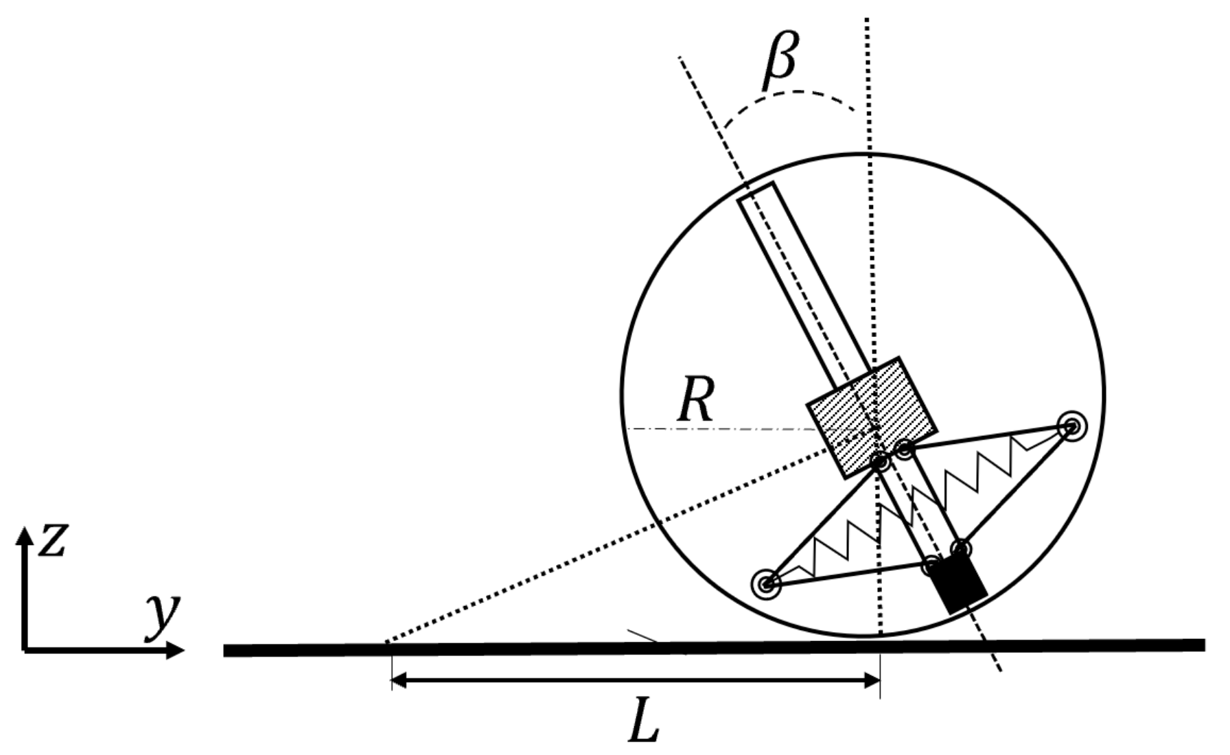
3.1. Analysis of Rolling

Rolling is the basic motion mode of a spherical robot, according to its operating principle, whose rolling motion mode can be equated to the model shown in Figure 5. The equivalent mass of the spherical shell is expressed as m 1 , the equivalent mass of the rolling drive module is expressed as m 2 and the equivalent mass of the jumping drive module (pendulum) is expressed as m 3 . The radius of the spherical shell is expressed as R and the length of the pendulum is expressed as r . It is assumed that there is no slip between the spherical shell and the ground during the linear rolling motion. The configuration of the spherical robot system can be determined by the angle φ of rotation of the spherical shell and the inclination angle θ between the pendulum and the vertical direction, and the generalized coordinates are ( φ , θ ). In the initial state, the contact point between the spherical shell and the ground is point O , the rolling distance of the spherical shell is
x 1 = R φ
and the position of the pendulum is
x 3 = x 1 + r   s i n θ z 3 = R r   c o s θ
Therefore, the kinetic energy of the system is the sum of the kinetic energy of the spherical shell, the rolling drive module and the jumping drive module, that is:
E k = E 1 + E 2 + E 3 = 1 2 m 1 v 1 2 + 1 2 J 1 ω 1 2 + 1 2 m 2 v 2 2 + 1 2 J 2 ω 2 2 + 1 2 m 3 v 3 2
where
v 2 = v 1 = R φ ˙ ω 1 = φ ˙ ω 2 = θ ˙ v 3 2 = x 3 ˙ 2 + z 3 ˙ 2
The horizontal plane where the center of the sphere is located is the zero potential energy plane. Thus, the potential energy of the whole system is
E p = m 3 g r c o s θ
According to the total kinetic energy and potential energy of the system, the Lagrange function is derived as follows:
L = E k E p
Substitute Equations (1)–(5) into Equation (6) to obtain
L = 1 2 m 1 R 2 + 1 2 m 2 R 2 + 1 2 m 3 R 2 + 1 2 J 1 φ ˙ 2 + 1 2 m 3 r 2 + 1 2 J 2 θ ˙ 2 + m 3 R r φ ˙ θ ˙ c o s θ + m 3 g r c o s θ
The Euler equation of the system can be presented as follows:
d d t L q J ˙ L q j = Q j ,   ( j = 1 , 2 )
where q 1 = φ , q 2 = θ and the generalized force is the torque of the motor τ
According to Equations (7) and (8), we can get
m 1 R 2 + m 2 R 2 + m 3 R 2 + J 1 φ ¨ + m 3 R r θ ¨ cos θ m 3 R r θ 2 ˙ sin θ = τ m 3 R r φ ¨ cos θ + m 3 r 2 + J 2 θ ¨ + m 3 g r sin θ = τ
Which describes the rolling configuration of the spherical robot driven by DC motors with constant torque.
The numerical simulation method is used to analyze the effect of the mass of the spherical shell and the mass of the pendulum (jumping drive module) on θ in the rolling motion of the spherical robot. As shown in Figure 6a, with the increase of the mass of the spherical shell m 1 , the amplitude of θ increases and the oscillation frequency of θ decreases. As shown in Figure 6b, with the increase of the mass of the pendulum m 3 , the amplitude of θ decreases and the oscillation frequency of θ increases, which is similar to that of the “inverted pendulum”.
Note: the length of the moment arm of the pendulum has a great influence on the angle θ in the system. With the increase of the moment arm, the amplitude of θ decreases and the oscillation frequency increases, as shown in Figure 7.
As the amplitude of θ decreases, the motion state of the system tends to be more stable. Therefore, we should try to reduce the mass of the spherical robot shell, increase the mass of the spherical robot’s internal pendulum, as well as extend the moment arm when designing the prototype. But in the actual design process, the interference of the mechanism movement should also be considered.

3.2. Analysis of Steering

The steering of the spherical robot is jointly acted by the motor controlling rolling and steering. The steering performance of the spherical robot is analyzed: the radius of the spherical shell is expressed as R and the maximum angle of the internal pendulum bias to the left and right direction is expressed as β , as shown in Figure 8, the minimum steering radius of the spherical robot is
L = R / t a n β
Equation (10) shows that the steering radius of the spherical robot is related to the size of the spherical shell and the deviation angle of the internal pendulum to the left and right direction. With the decrease of the size of the spherical shell and the increase of the deviation angle of the internal pendulum to the left and right, the steering radius of the spherical robot will decrease and the action will be more flexible.

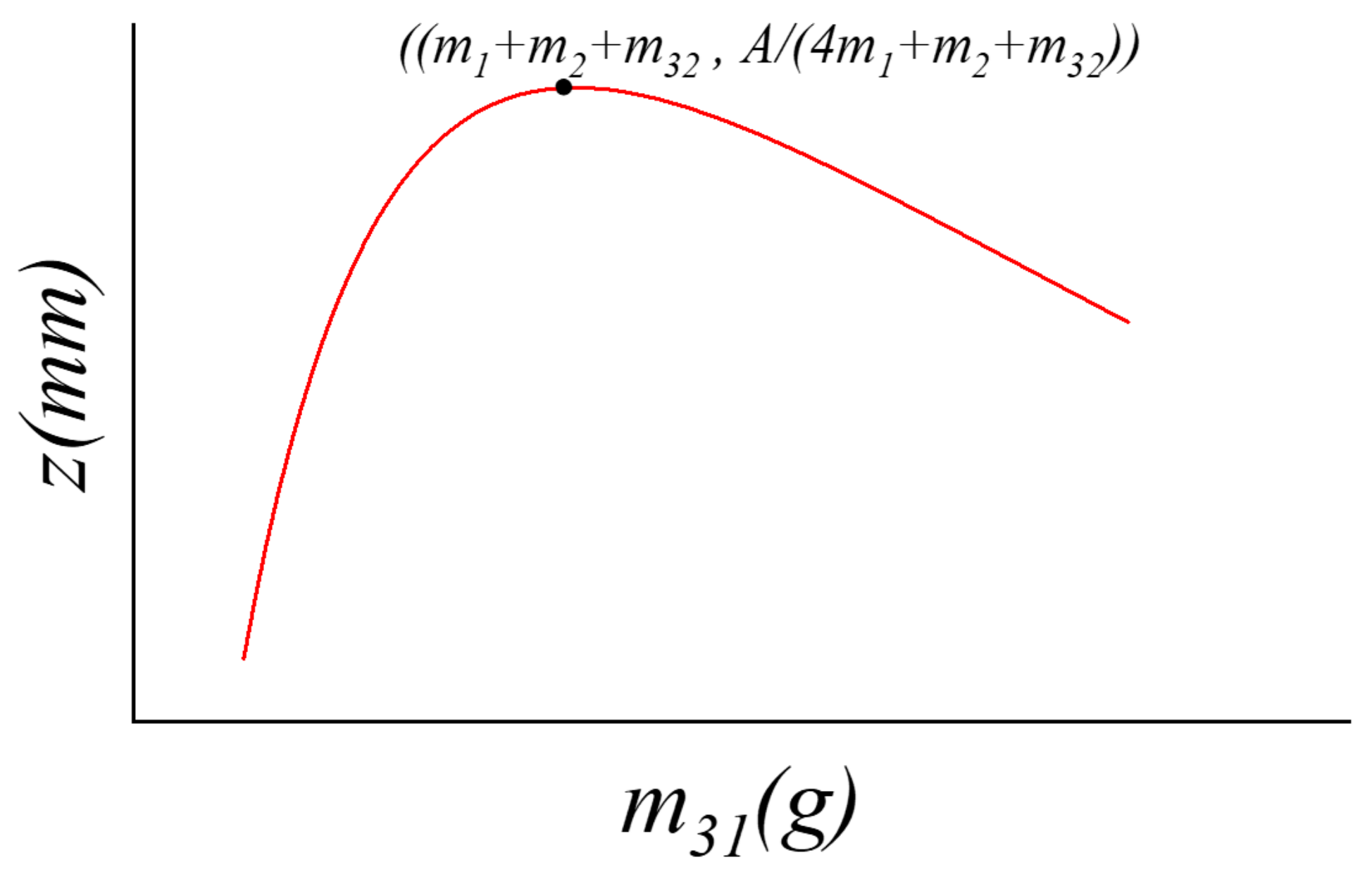
3.3. Analysis of Jumping

The jumping function of the spherical robot is realized by controlling the spring energy storage and releasing by the jumping drive module, as shown in Figure 9. m 31 is the mass of the mechanism case, m 32 is the mass of the six-bar mechanism, m 1 is the mass of the spherical shell, m 2 is the mass of the frame, L 1 is the length of the spring in the limit energy storage position, L 2 is the original length of the spring without stretching, k is the stiffness coefficient of the linear spring.
The internal collision is assumed to be inelastic and the energy loss caused by friction is ignored. The relation between the storage energy E and the velocity of the mechanism case before the collision is:
E = 1 2 k Δ L 2 = 1 2 m 31 v 1 2 .
where, Δ L = L 2 L 1 .
When the mechanism case moves upward and collides with the second frame, according to the law of momentum conservation, there is:
m 31 v 1 = m 1 + m 2 + m 31 + m 32 v 2 .
where, v 2 is the initial jumping speed of the system, and the jumping height of the system can be expressed as
z t = v 2 t 1 2 g t 2 .
According to Equation (13), the maximum vertical jumping height of the spherical robot under ideal conditions is
z max = m 31 m 1 + m 2 + m 31 + m 32 2 k Δ L 2 2 g .
According to Equation (14), when the mass of each part of the spherical robot and the tensile length of the spring Δ L are constant, the maximum jumping height is mainly determined by the spring stiffness coefficient. The effect of different spring stiffness coefficients on the jumping height of the spherical robot is shown in Figure 10.
The selection of spring is limited by the torque of the motor. In addition to trying to select the appropriate spring, adjusting the mass size of m 31 can also help the spherical robot to obtain a better jumping height under the condition that other parts of the mass remain the same. The curve of z m a x = m 31 m 1 + m 2 + m 31 + m 32 2 A is shown in the Figure 11. When the mass of m 31 approaches to the m 1 + m 2 + m 32 , a more desirable jumping height of 1 4 m 1 + m 2 + m 32 A can be obtained, where A denotes the relevant parameter k Δ L 2 2 g of the spring.

4. Experiments

According to the structure design scheme and theoretical analysis results, a spherical robot prototype is designed. The total mass of the prototype is about 800 g and the diameter is 150 mm. The specific parameters are shown in the following Table 1. Rolling and jumping abilities were tested and characterized in different scenarios.

4.1. Rolling Ability Test

The rolling motion ability directly affects the steering and climbing ability of the spherical robot. In this section, the rolling straightness, speed, steering radius and climbing angle of the spherical robot are tested.

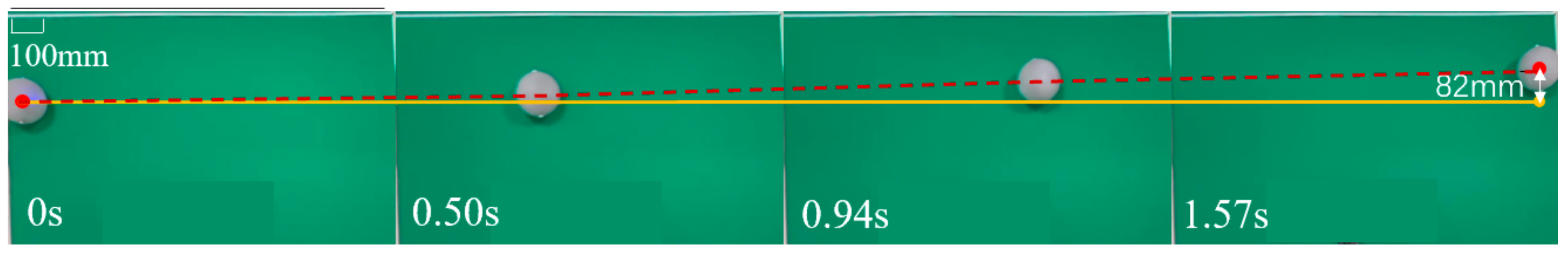
4.1.1. Straight Rolling Test

In order to reduce the testing error of the robot in the rolling process, the spherical robot is placed on the ground with high friction to test its straight rolling ability, as shown in Figure 12, where the yellow line is the reference line and the red line is the actual rolling track of the spherical robot. According to the measurement, the robot moves forward about 1200 mm in straight rolling mode with a rolling speed of about 800 mm/s, and the deviation distance is about 82 mm.

4.1.2. Steering Test

The steering of the spherical robot is realized by the relative rotation of the second frame and the first frame. The second frame rotates to the maximum angle to measure the minimum steering radius of the robot. The spherical robot was placed on the ground to complete the semicircle trajectory, as shown in Figure 13. Frames 1–4 describes the position of the spherical robot at different times, and the yellow line is the approximate trajectory. According to the measurement results, the minimum steering radius of the spherical robot is about 150 mm.

4.1.3. Climbing Test

A slope is built on the horizontal ground with an acrylic plate. By adjusting the inclination of the slope, the maximum slope of the spherical robot climbing at the fastest rolling speed is about 10° and the climbing test process is shown in Figure 14.

4.2. Jumping Ability Test

In order to reduce energy loss originated from friction and other factors, the maximum jump height of the spherical robot is measured by the vertical jump test and the ability of the spherical robot to jump in multiple directions is verified.

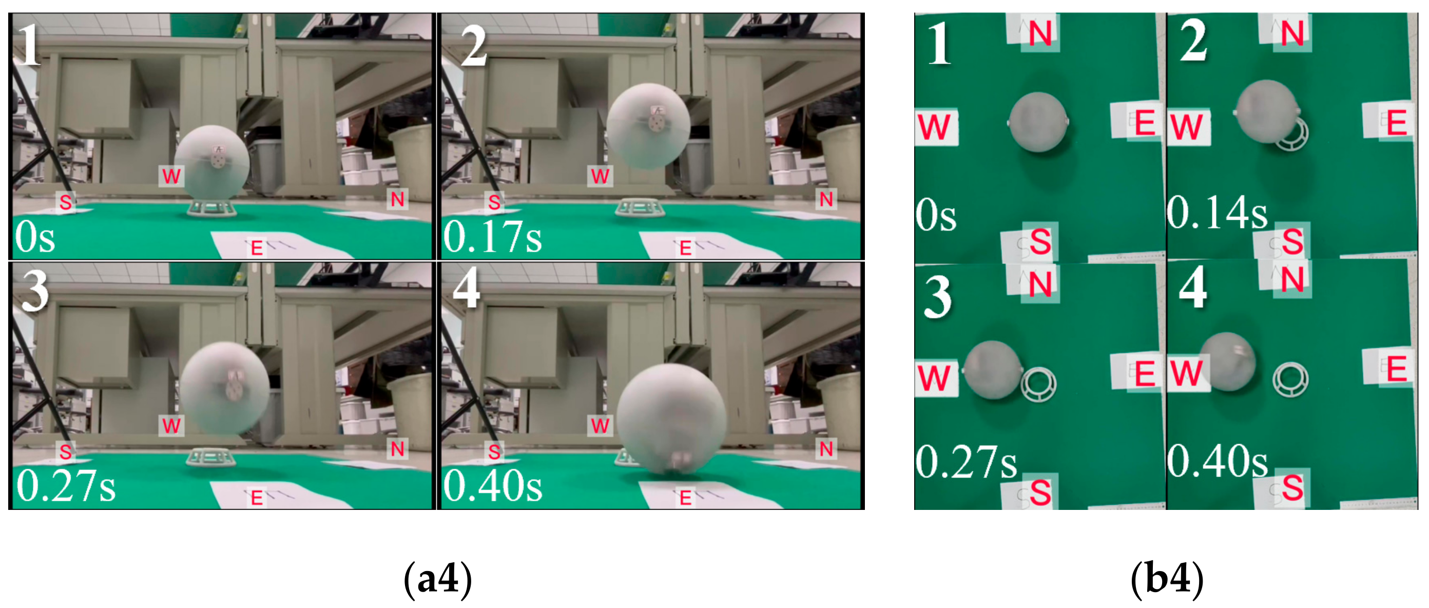
4.2.1. Vertical Jumping Test

The spherical robot is placed on the support seat to make the internal jump driving mechanism perpendicular to the ground. By controlling the movement of the internal jump driving module, the energy storage and release of the spring are completed to realize the jump movement of the spherical robot. Two linear springs with a stiffness coefficient of 147 g/mm are selected. After measurement, the final vertical jumping height is about 170 mm, 1.13 times its own height. The experimental process is shown in Figure 15.

4.2.2. Multidirectional Jumping Test

In order to test the jumps ability of a spherical robot in multiple directions in place, a support with a groove is designed and the spherical robot was placed in the groove. No movement of the spherical robot occurs when the rotation of the 2-DOF frame shifts the center of mass, which simulates a situation where the spherical robot falls into a narrow gully and the sphere is limited. When the first frame is rotated, the spherical robot can jump in the north and south directions, as in Figure 16(a1,a2,b1,b2), and when the second frame is rotated, the spherical robot can jump in the west and east directions, as in Figure 16(a3,a4,b3,b4). Two views of the jumping process of the spherical robot are shown, where (a1–a4) show the side view of the jump in four directions and (b1–b4) show the top view of the jump in four directions. When the two frames are combined to rotate, multiple jumping directions can be formed, giving the spherical robot the ability to jump in multiple directions.

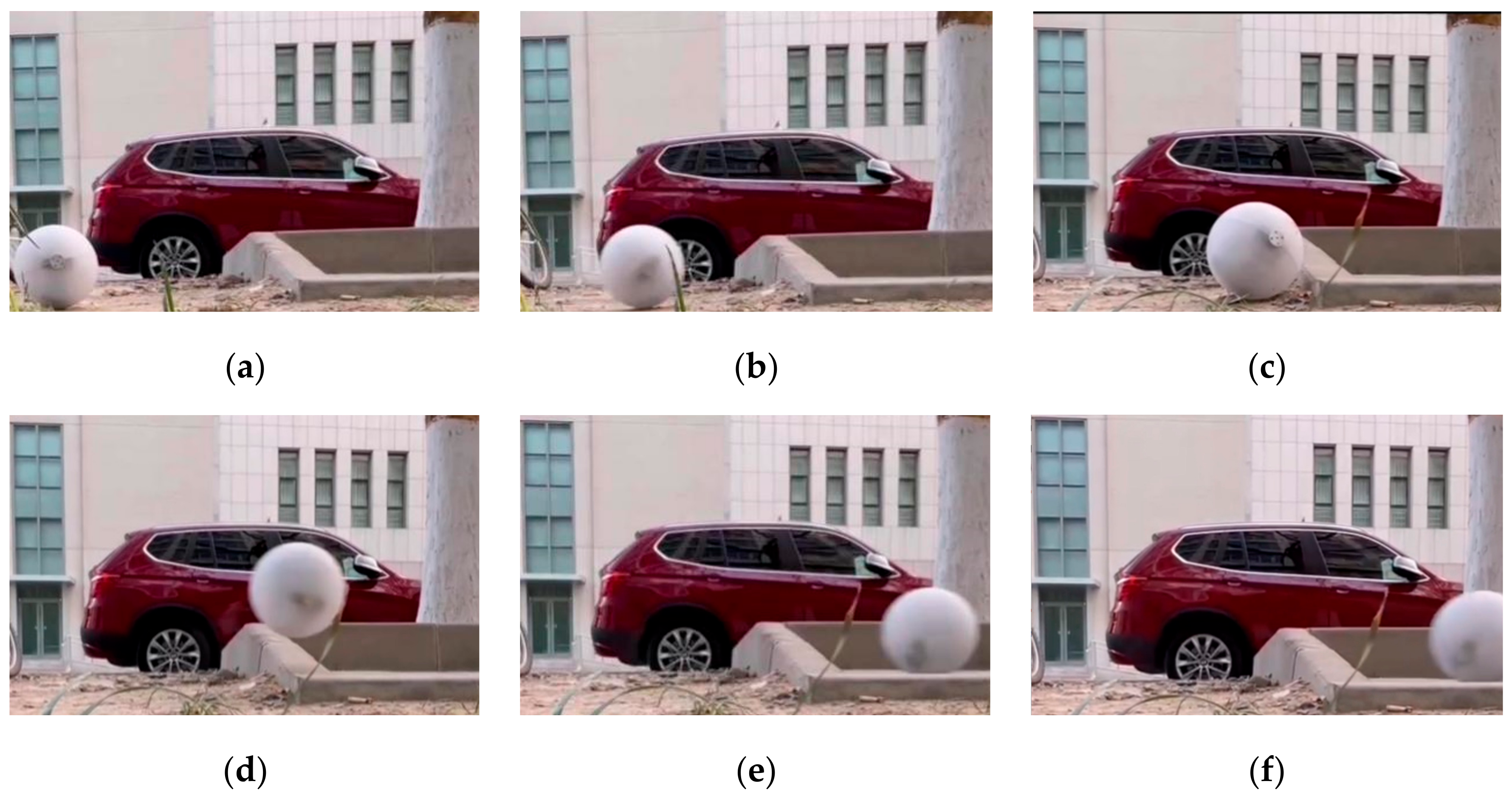
4.3. Obstacle Crossing Ability Test

The spherical robot is placed in the actual environment with obstacles, and the ability to cross the obstacles through the switching of rolling and jumping modes is tested, as shown in Figure 17a–c indicate that the spherical robot rolls from rest and encounters an obstacle, and d–f indicate that the spherical robot crosses the obstacle by jumping. The experiment proves that the spherical robot has good rolling walking and obstacle surmounting ability in a complex environment.

4.4. Comparison of Test Results with Theoretical Values

Substituting the parameters of the robot prototype into Equations (9), (10) and (14), the theoretical model with a rolling speed of 1005 mm/s, a steering radius of 131 mm and a jumping height of 212 mm is obtained. Comparing the theoretical values with the measured data, as shown in Table 2, there is some error between the theoretical value and actual values. Considering that the theoretical data comes from the simplified model, and the energy loss caused by mechanical friction and transmission efficiency among internal structural parts during the actual movement of the prototype is not considered, the error between the theoretical value and the actual value is considered to be within a reasonable range.

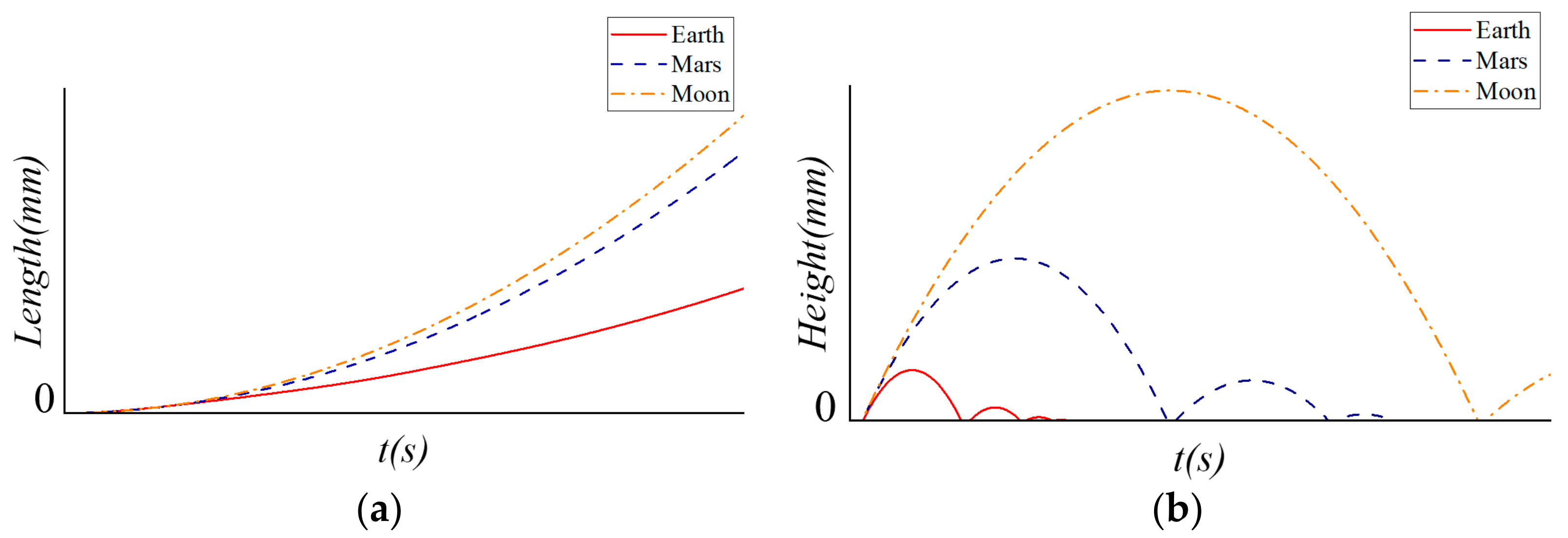
4.5. Applicability in Microgravity

Considering the future application scenarios, the rolling and jumping capabilities of the spherical robot under different gravity environments on the moon and Mars are analyzed by numerical simulation. By altering the gravity conditions, it can be concluded from Equations (9) and (14) that the spherical robot shows better motion in the microgravity environment, as shown in Figure 18.

5. Conclusions

In this paper, a spherical robot with both rolling and jumping modes is designed. By adjusting the position of the pendulum and the rotation angle of the two frames, the robot can roll, turn and jump in multiple directions. The motion characteristics of the spherical robot are analyzed by establishing the dynamic model. In addition, the influence of the dimensions and weights of the robot components on its motion capability is analyzed by numerical simulation. The results show that the rolling stability of the spherical robot can be improved by decreasing the mass of the spherical shell while increasing the mass of the internal “pendulum” and extending the moment arm of the “pendulum”. When the mass of the mechanism case in the jumping module is equal to the total mass of the remaining parts of the spherical robot, the jumping height reaches the maximum. Based on the numerical simulation results, a spherical robot prototype is designed, and its motion performance is tested and characterized. The maximum rolling speed of the spherical robot is measured to be approximately 800 mm/s, with a lateral deviation of approximately 82 mm over a distance of 1200 mm, and the minimum steering radius of the spherical robot is approximately 150 mm. The vertical jump height of the spherical robot is 170 mm, and the ability of the spherical robot to jump in multiple directions is verified. The actual motion parameters of the spherical robot are compared with the theoretical values. Considering the energy loss caused by inelastic collision and friction between parts, the error between the two values is acceptable. It is worth mentioning that, in order to verify the applicability of the spherical robot motion mechanism in different gravity environments, the microgravity environments of the moon and Mars are simulated, and the rolling and jumping ability are analyzed. The results show that in the microgravity environment, the spherical robot can show faster rolling speed and higher jumping height, which preliminarily verifies the feasibility of the robot to move quickly and widely in the unstructured terrain of an unknown planet.
In the future, the internal space layout of the spherical robot will be rationalized and a lightweight design will be carried out in combination with the specific detection function load, to improve its detection capability while ensuring superior motion performance. On this basis, the autonomous control and coordination methods of spherical robots are studied, which lays a foundation for the cluster operation of microrobots for deep space exploration.

Author Contributions

Conceptualization, F.W. and S.N.; data curation, F.W. and B.L.; methodology, F.W. and B.L.; software, H.W.; investigation, C.L.; resources, P.W.; writing—original draft preparation, F.W.; writing—review and editing, F.W.; supervision, B.L.; project administration, S.N. and B.L.; All authors have read and agreed to the published version of the manuscript.

Funding

This research received no external funding.

Institutional Review Board Statement

Not applicable.

Informed Consent Statement

Informed consent was obtained from all subjects involved in the study.

Acknowledgments

This work was sponsored by Technology 173 Program Technical Field Fund(2019-JCJQ-JJ-459).

Conflicts of Interest

The authors declare no conflict of interest.

References

  1. Jennings Taylor, E.; Jackson, G.S. Perseverance Rover Lands on Mars. Electrochem. Soc. Interface 2021, 30, 79–80. [Google Scholar] [CrossRef]
  2. Binlong, Y.; Qian, Y.; Xiao, L.; Michalski, J.R.; Li, Y.; Wu, B.; Qiao, L. Geomorphologic exploration targets at the Zhurong landing site in the southern Utopia Planitia of Mars. Earth Planet. Sci. Lett. 2021, 576, 117199. [Google Scholar] [CrossRef]
  3. Kesner, S.B.; Plante, J.S.; Boston, P.J.; Fabian, T.; Dubowsky, S. Mobility and power feasibility of a microbot team system for extraterrestrial cave exploration. In Proceedings of the 2007 IEEE International Conference on Robotics and Automation, Rome, Italy, 10–14 April 2007; pp. 4893–4898. [Google Scholar] [CrossRef]
  4. Balaram, J.; Aung, M.M.; Golombek, M.P. The Ingenuity Helicopter on the Perseverance Rover. Space Sci. Rev. 2021, 217, 1–11. [Google Scholar] [CrossRef]
  5. Halme, A.; Schonberg, T.; Wang, Y. Motion control of a spherical mobile robot. In Proceedings of the International Workshop on Advanced Motion Control, AMC ’96, Mie, Japan, 18–21 March 1996; IEEE: New York, NY, USA, 1996; Volume 1, pp. 259–264. [Google Scholar]
  6. Mukherjee, R.; Minor, M.A.; Pukrushpan, J.T. Simple motion planning strategies for spherobot: A spherical mobile robot. In Proceedings of the 38th IEEE Conference on Decision and Control, Phoenix, AZ, USA, 7–10 December 1999; IEEE: New York, NY, USA, 1999; Volume 3, pp. 2132–2137. [Google Scholar]
  7. Fiorini, P.; Hayati, S.; Heverly, M.; Gensler, J. A Hopping Robot for Planetary Exploration. In Proceedings of the 1999 IEEE Aerospace Conference, Snowmass, CO, USA, 7 March 1999. [Google Scholar]
  8. Zhao, B.; Li, M.; Yu, H.; Hu, H.; Sun, L. Dynamics and motion control of a two pendulums driven spherical robot. In Proceedings of the IEEE/RSJ 2010 International Conference on Intelligent Robots and Systems, Taipei, Taiwan, 18–22 October 2010; pp. 147–153. [Google Scholar]
  9. Joshi, V.A.; Banavar, R.N. Motion analysis of a spherical mobile robot. Robotica 2009, 27, 343–353. [Google Scholar] [CrossRef]
  10. Ferrière, L.; Campion, G.; Raucent, B. ROLLMOBS, a new drive system for omnimobile robots. Robotica 2001, 19, 1–9. [Google Scholar] [CrossRef]
  11. Ahn, S.S.; Lee, Y.J. Novel Spherical Robot with Hybrid Pendulum Driving Mechanism. Adv. Mech. Eng. 2014, 2014, 456727. [Google Scholar] [CrossRef]
  12. Ahn, S.S.; Kim, Y.M.; Lee, Y.J. A deformable spherical robot with two arms. J. Inst. Control Robot. Syst. 2010, 16, 1060–1067. [Google Scholar] [CrossRef] [Green Version]
  13. Armour, R.; Paskins, K.; Bowyer, A.; Vincent, J.; Megill, W. Jumping robots: A biomimetic solution to locomotion across rough terrain. Bioinspiration Biomim. 2007, 2, S65. [Google Scholar] [CrossRef] [PubMed] [Green Version]
  14. Burdick, J.; Fiorini, P. Minimalist Jumping Robots for Celestial Exploration. Int. J. Rob. Res. 2003, 22, 653–674. [Google Scholar] [CrossRef]
Figure 1. (a) The front view of the rolling and jumping spherical robot. (b) The isometric view of a rolling and jumping spherical robot. (c) The rolling driving module of the spherical robot. (d) The jumping driving module of the spherical robot.
Machines 10 00126 g001
Figure 2. The internal structure of the mechanical case.
Machines 10 00126 g002
Figure 3. The execution process of the jumping drive structure.
Machines 10 00126 g003
Figure 4. (a) The spherical robot changes the jumping direction by rotating the first frame. (b) The spherical robot changes the jumping direction by rotating the second frame.
Machines 10 00126 g004
Figure 5. The simplified scheme of the rolling of a spherical robot.
Machines 10 00126 g005
Figure 6. (a) The effect of m 1 on θ . (b) The effect of m 3 on θ .
Machines 10 00126 g006
Figure 7. The effect of r on θ .
Machines 10 00126 g007
Figure 8. The simplified scheme of the steering of a spherical robot.
Machines 10 00126 g008
Figure 9. The simplified scheme of the jumping of a spherical robot.
Machines 10 00126 g009
Figure 10. The influence of springs with different stiffness coefficients on jumping height.
Machines 10 00126 g010
Figure 11. The influence of different values m 31 on the maximum jumping height.
Machines 10 00126 g011
Figure 12. Rolling motion of the spherical robot.
Machines 10 00126 g012
Figure 13. Steering motion of the spherical robot.
Machines 10 00126 g013
Figure 14. Climbing motion of the spherical robot.
Machines 10 00126 g014
Figure 15. Vertical jumping motion of the spherical robot.
Machines 10 00126 g015
Figure 16. Spherical robot jumps in multiple directions. (a1a4) Side views of the jumping motion. (b1b4) Top views of the jumping motion.
Machines 10 00126 g016aMachines 10 00126 g016b
Figure 17. The spherical robot jumps over obstacles. (ac) Rolling motion and encountering obstacles. (df) Obstacle crossing by jumping.
Machines 10 00126 g017
Figure 18. Performance of spherical robot in different gravity environments. (a) Rolling in the environment of earth, moon and Mars. (b) Jumping in the environment of earth, moon and Mars.
Machines 10 00126 g018
Table 1. Nomenclature of the model and the corresponding robot specifications.
Outer Shell
 Mass m 1 188 g
 Radius R 75 mm
 Moment of inertia J 1 6.0 × 10⁵ g·mm2
Rolling drive module
 Mass m 2 173 g
 Moment of inertia J 2 1.6 × 10⁵ g·mm2
 Pendulum length L 23 mm
 Motor rated torque τ 49 mN·m
 Maximum deflection angle of the second frame β 30°
Jumping drive module
 Mass of m 31 390 g
 Mass of six-bar mechanism m 32 38 g
 Stiffness coefficient of spring k 147 g/mm
 The stretch length of the spring Δ L 48 mm
Table 2. Motion characteristics of the theoretical model and prototype.
The Theoretical ValueThe Actual ValueThe Relative Error
Rolling velocity1005 mm/s800 mm/s20.4%
Steering radius131 mm150 mm14.5%
Jumping height212 mm170 mm19.8%
Publisher’s Note: MDPI stays neutral with regard to jurisdictional claims in published maps and institutional affiliations.

