1. Introduction
The finishing of functional surfaces, especially tooth flanks, has gained importance in recent years. Reasons for this can be seen, for example, in the energy revolution, which has led to a large increase in the number of gear drives produced for wind turbines on the one hand and to an increase in the power output of modern wind turbines on the other. To generate more power, rotor diameters are increased whereas the rotary speeds decrease, which leads to higher torques [
1]. To reduce the risk of pitting in these highly stressed gears and to increase the load-bearing capacity, higher surface qualities on the gear flanks are required. Besides the reduction in the risk of pitting and the improvement of load-carrying capacity, an increase in surface quality can also improve gear efficiency [
2,
3,
4,
5]. In addition, the acoustic emissions of gearboxes can be reduced by a low tooth flank surface roughness [
6,
7]. To achieve the required high surface quality, an additional finishing step after the grinding process is usually necessary. Besides the low surface roughness, another demand on the finished surface is the preservation of grinding grooves in the feed direction, as these could have a positive influence on the transport of lubricant within the gear unit.
A widespread manufacturing process for finishing tooth flanks is mass finishing, in which the workpiece surface is smoothed using abrasives that are set in motion relative to the workpiece by external stimulation such as rotation or vibration [
8]. High surface qualities can be achieved without negatively influencing the shape and dimensional accuracy of the gear tooth profile and flank line. A special procedure for this is Isotropic Super Finishing (ISF
®). This mass-finishing process uses an active chemical added to the compound to create a thin layer of oxide on the workpiece’s surface. The abrasives separate this surface layer in the subsequent process step, whereby roughness values of Ra < 0.02 µm can be achieved [
9,
10]. However, it is an additional, cost-intensive production step outside of the grinding machine. Disadvantages are also the high process time associated with processing and the need for an active chemical, which represents an additional cost factor for the finishing process as well as environmental pollution. Furthermore, small and medium-sized enterprises (SMEs) often do not have the necessary equipment, so the finishing of the gearwheels is often outsourced to third parties.
Due to the increasing requirements in terms of shape and dimensional accuracy as well as the surface quality of gears and the resulting increased demand for finished gearwheels, manufacturing processes that have not been used up to now are moving into focus not only for small quantities but also for series production. A finishing process that is integrated into the grinding machine and can achieve results comparable to vibratory finishing without having to unclamp the workpiece or use polluting chemicals would be a great benefit. It would give particularly SMEs the opportunity to execute one of the final, quality-determining process steps in the production of gearwheels themselves, which would increase their independence and thereby provide greater flexibility. By using abrasive brushing tools for the finishing of gearwheels, the surface quality can be improved while cost- and resource-intensive process steps outside of the grinding machine can be substituted. In general, the flexible filaments of the brushing tools are suitable for processing complex geometries such as those found in gearwheels. At the same time, brushing processes can produce high surface qualities without negatively affecting the shape and dimensional accuracy [
11,
12,
13]. Thus, both requirements for the finishing of gearwheels are met.
As part of a previous study conducted at the Institute for Machine Tools and Factory Management (IWF) of the Technische Universität Berlin, it was shown that the finishing of the tooth flanks with abrasive brushing tools is suitable for improving the surface quality without negatively affecting the macro-geometry of the gearwheel [
14]. The surface quality of a brushed tooth flank can be deliberately improved depending on the process parameters and the tool specification, by which the technological feasibility of a machine-integrated finishing process was demonstrated.
The main aim of the project, the results of which are presented in this paper, was to test the suitability of the brushing process for industrial use. To achieve this goal, wear criteria for the use of brushing tools should be recognized and defined. Considering those, tool life and process reliability were to be determined and optimized. Therefore, experiments with two different brushing tool specifications were carried out, in which reference gearwheels (z = 39, mn = 10 mm, b = 200 mm) with a defined initial surface quality were finished with the brushing process that was developed in the preceding study. Besides the influence of the tool specification and the process parameters on the achievable surface roughness, another objective of the investigations was to determine the influence of the initial surface roughness created by the upstream grinding process.
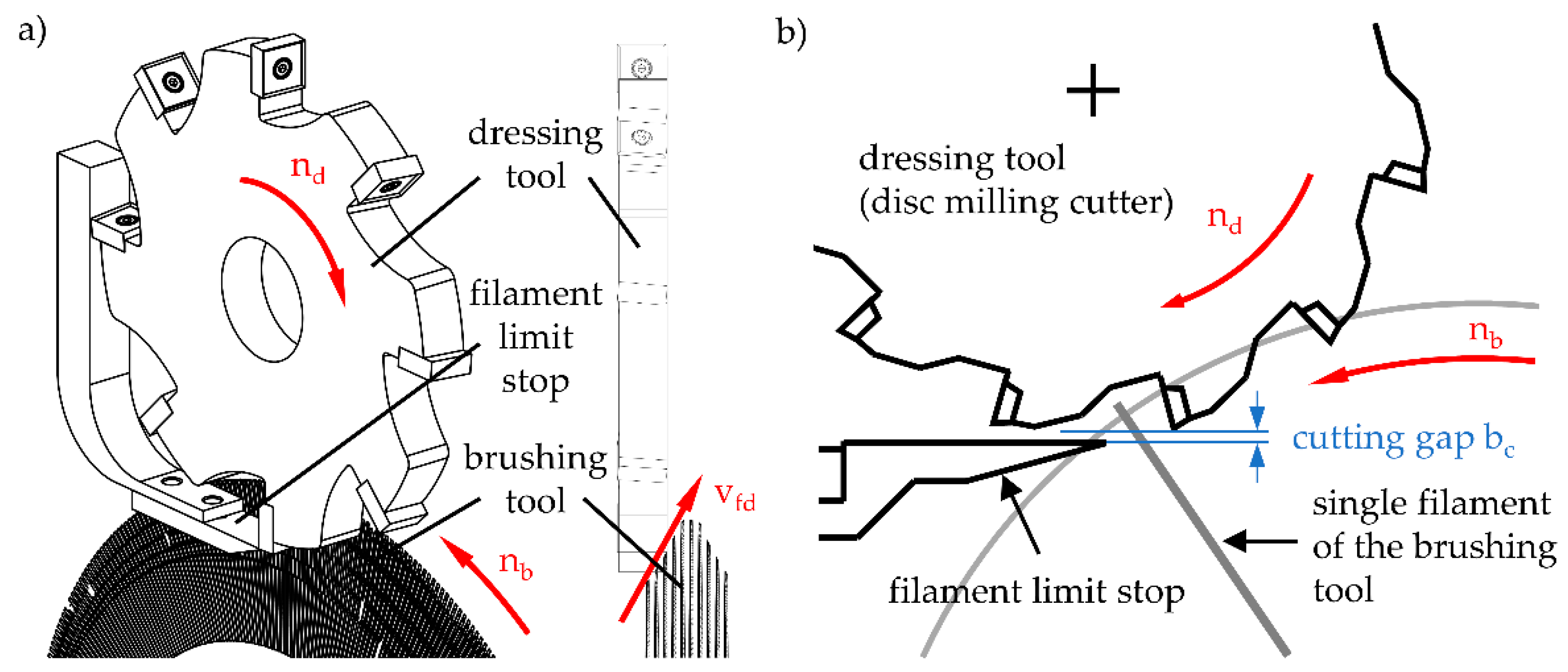
In addition, a conditioning technology for the dressing and the profiling of the abrasive brushing tools within the grinding machine was to be developed and implemented. The basic approach was to use a disc milling cutter as a dressing tool with which the filaments could be trimmed by a shear mechanism. By integrating the design into the dressing system of the grinding machine, the brush can be conditioned to any required shape, for example, the geometry of the respective gear gap. After testing the application to determine suitable dressing parameters, the possibility of restoring a worn-out brushing tool by trimming the filament tips was examined.
2. Materials and Methods
2.1. Grinding Machine and Force Measurement
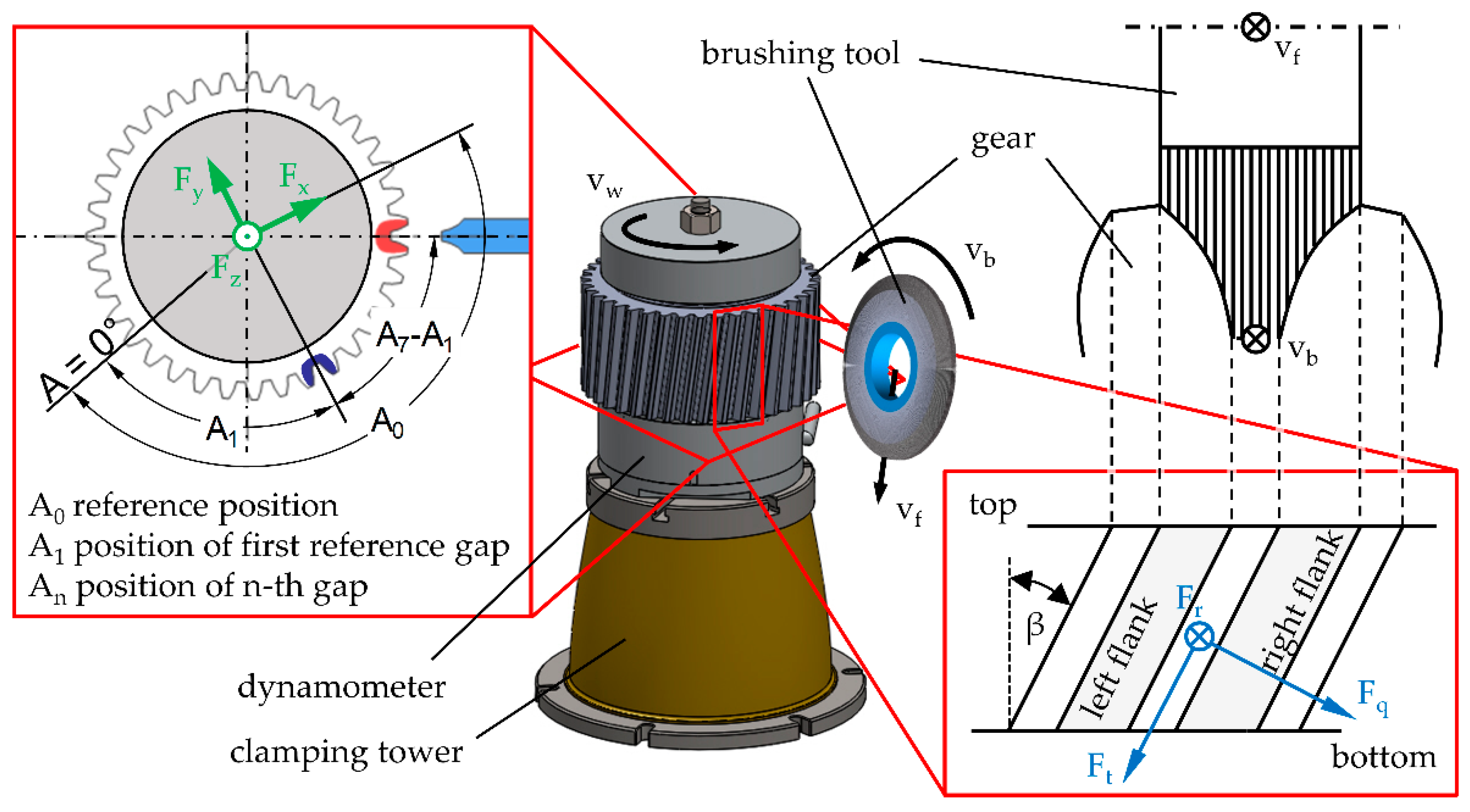
The experiments were carried out on a gear profile grinding machine of type ZP 12 by Kapp Niles GmbH & Co. KG, Coburg, Germany, (short: KAPP NILES). A specially designed six-component dynamometer by Kistler Instrumente AG, Winterthur, Switzerland, was used to record dynamic and quasi-static forces and moments exerted on the workpiece. The dynamometer was installed on the clamping tower such that the workpiece can be mounted directly on top of it. Thereby, forces and torques can be measured in all spatial directions. The dynamometer was characterized by high stiffness and eigenfrequency, whereby the machining forces of grinding processes of large gearwheels can be measured. To protect against the ingress of splash water and cooling lubricant, an additional sealing air housing was applied, which means that it corresponds to protection class IP67 and possible temperature influences of the cooling lubricant on the dynamometer can be avoided.
A measuring chain was developed to determine and evaluate the grinding forces during gear grinding. The charges of the quartz crystal elements were amplified using industrial ICAM charge amplifiers, which were transmitted to a measurement computer via a measurement card. In addition, the current position of the workpiece axes (A position) and the spindle power were read out using the digital-to-analog converter (DAU) of the gear grinding machine. All voltage signals were recorded using the data acquisition and processing software LabVIEW by National Instruments, Austin, TX, USA.
To process and evaluate the measurement data, appropriate software was developed in the
MATLAB programming environment by
MathWorks, Natick, MA, USA, which enabled the calculation of radial, normal, and tangential forces with regard to the respective gap. The machining forces were related to the tooth gap position as shown in
Figure 1, also considering the helix angle β.
2.2. Gear Measurement
In order to determine the influence of the finishing process on the macro-geometry of the tooth flanks, the gear geometry was measured before and after brushing. The assessment of the toothing geometry was mainly based on the profiles, whereby the profile angle error f
Hα was primarily considered. The measurements for the investigations were recorded and evaluated on a gear measuring machine of type ZMC-550 by
Carl Zeiss AG, Oberkochen, Germany, considering DIN ISO 1328-1 [
15].
2.3. Surface Roughness Measurement
To examine the surface quality, the surface roughness was measured in the middle of the tooth profile at three different points per tooth flank. The measurements were carried out with a mobile surface measuring device of type MarSurf PS 10 by
Mahr-Gruppe, Göttingen, Germany. The measurements on the tooth flanks were conducted using a process standardized by CNC code within the grinding machine. For this purpose, a device was constructed that made it possible to repeat the measurements in a reproducible manner so that the exact same positions on the tooth flanks could be measured before and after the brushing process. The assessment of the surface roughness was mainly based on the arithmetic average roughness Ra, which currently is the reference parameter in the industry. The measurement conditions for the roughness measurements, listed in
Table 1, corresponded to DIN EN ISO 4287 and were retained for all measurements within the scope of the investigations presented in this paper [
16].
2.4. Microscopic Imaging
For the qualitative identification of wear forms, microscopies of individual filaments were taken at different positions across the width of the tool at specific intervals. For each examination, at least ten filaments were observed in order to guarantee statistical validation. The images were made with a VHX-5000 digital microscope by Keyence Deutschland GmbH, Neu-Isenburg, Germany.
2.5. Workpiece and Brushing Tools
The workpiece used for the experiments presented in this paper was a planetary gear made of 18CrNiMo7-6 with the specifications listed in
Table 2. It was the equivalent to the test gearwheels used in the preceding study so that the results could be compared directly and the investigation strategy could be based on the previous findings. A new gearwheel was used for each test series and ground according to the defined initial roughness requirements.
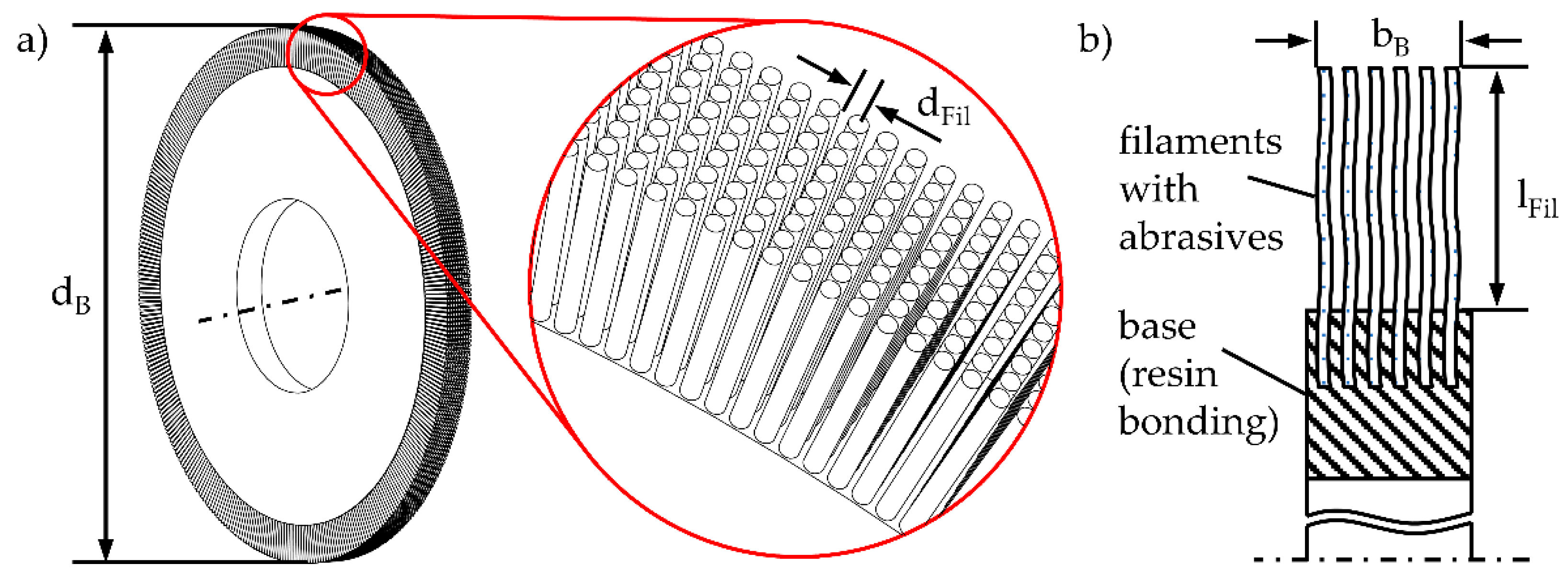
Brushing tools in general consist of a resin base body into which abrasive filaments are molded. The schematic structure of a brushing tool is shown in
Figure 2. The brushing tool is characterized geometrically by the outer diameter of the brush d
B, the brush width b
B and the free filament length l
Fil. The filament specification can be adjusted in relation to the base material, the abrasive, its diameter d
Fil, and the corrugation. Wavy filaments are used to increase the rigidity of the entire tool due to the increased interactions between filaments.
Depending on the area of application, different abrasives can be embedded in the filaments, which are mostly made of polyamide 6.12 [
17]. The mass fraction of the abrasive is between 20% and 40%. Whereas diamond is used when processing ceramics, aluminum oxide (Al
2O
3) or silicon carbide (SiC) are mostly used when processing metallic workpieces [
5]. The grain size can be adjusted depending on the desired work result: If the focus lies on high material removal rates, coarse grains may be used, while finer grains which do not penetrate the workpiece surface deeply are more suitable for smoothing the surface and removing roughness peaks [
17]. In addition to the grain, the matrix material can also be flexibly adjusted. Depending on the stiffness of the filament, the processing forces change, and thus, the achievable surface roughness. Another considerable factor for the choice of the matrix material is the temperature development, which depends significantly on the circumferential brush speed [
18].
Following the findings of the preceding study, two different brushing tool specifications, namely S240x0.75 and S320x0.60, were investigated [
14,
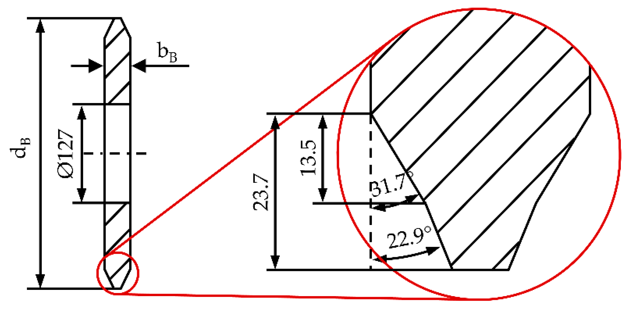
19]. The brushing tools were profiled by the manufacturer according to the approximate geometrical shape of the gear gaps as shown in
Figure 3. All other relevant specification parameters are listed in
Table 3.
3. Results and Discussion
3.1. Tool Life and Process Reliability
In order to determine the tool life and the process reliability, the process was evaluated on the basis of the work result in relation to the reduction in the surface roughness ΔRa and the correlating machining force F
z. In addition, the brushing tools were qualitatively assessed by microscopic examinations of individual filaments in order to determine the wear mechanisms. To compare the two different brushing tool specifications precisely, a new gearwheel was ground such that the tooth flanks have a defined initial surface roughness of Ra
ini = 0.4 ± 0.02 µm for each test series. To achieve the defined initial state, the conventional grinding wheel was dressed with a diamond dressing roller before the machining of every single gap. The brushing process parameters, which are listed in
Table 4, were chosen according to a technology screening with the goal to reach the target range of Ra = 0.2 ± 0.05 µm after brushing.
For a better understanding of the process and especially the definition of the brushing infeed a
eb, the kinematics and the process parameters are shown schematically in
Figure 4. The main process kinematic is completely analogous to the gear profile grinding process. Due to the dynamic behavior of the filaments, the brushing infeed a
eb cannot be conceived as a fixed geometric variable as in grinding processes. In the case of brushing, the infeed can also be interpreted as a pretensioning of the filaments. It is defined as the radial positioning of the brush relative to the position in which the circumference of the brush touches the tooth root. To achieve the highest reduction in the surface roughness, the brush is counter-rotating in relation to the feed direction.
Furthermore, the engagement time t
e is introduced according to Equation (1) in order to quantify the load and the resulting service life of the brushing tool. The brushing distance s
b is defined as the product of the gearwheel face width b, the number of strokes n
str, and the number of brushed gearwheel gaps z
b, and is related to the feed speed v
f. In addition, the specific engagement time t
e* is defined according to Equation (2), which describes the duration for which the brushing tool is engaged per gap.
3.1.1. Brushing Tool Specification S320x0.60
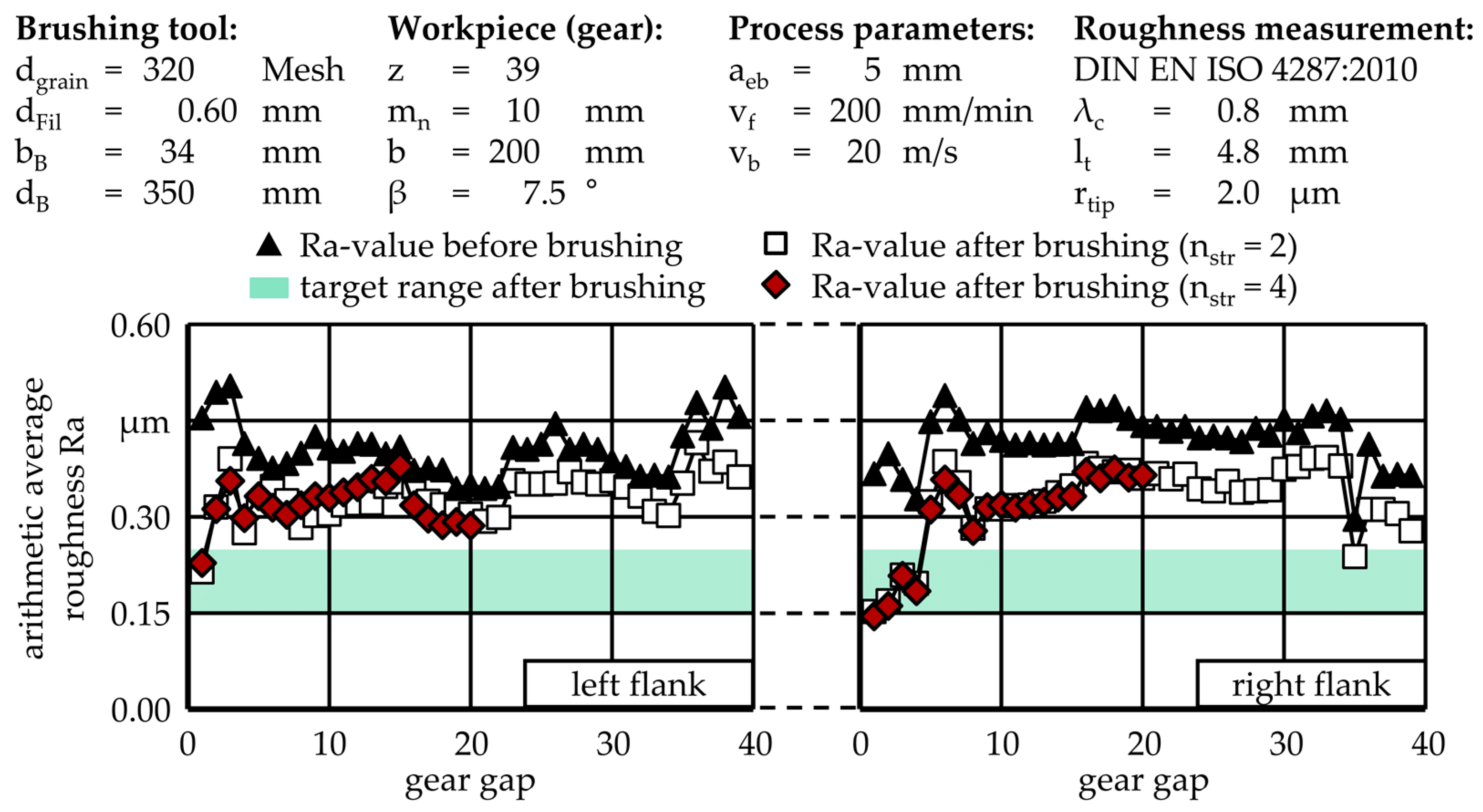
For the test series with the brushing tool S320x0.60, the test gearwheel was pre-ground to an average initial roughness of
= 0.41 µm with a standard deviation of σ = 0.041 µm. As can be seen in
Figure 5, the average roughness value achieved after brushing with two strokes is only
= 0.33 µm and has a standard deviation of σ = 0.047 µm. With C
p = 0.35 and C
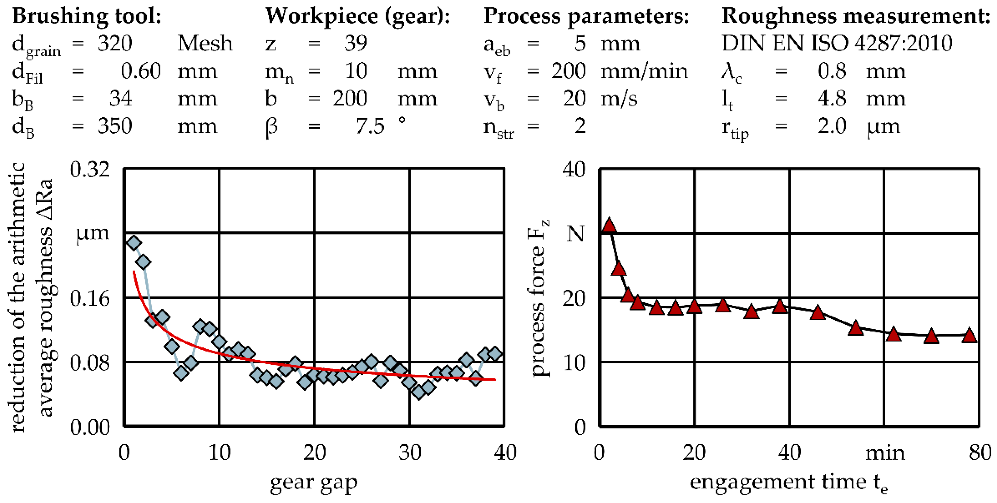
pK = −0.55, the process capability indices are not particularly meaningful due to the non-achievement of the target range (Ra = 0.2 ± 0.05 µm). Based on the change in the arithmetic average roughness ΔRa and the correlating process force F
z, shown in
Figure 6, it becomes clear that the removal rate decreases rapidly within the first four machined tooth gaps or an engagement time of t
e ≈ 8 min. Accordingly, the target area could only be reached in the first gaps that were processed. The strong influence of this initial phase was still unknown during the technology screening to determine the process parameters and was therefore not considered. In order to check whether the defined tolerance range can be achieved with a longer specific engagement time t
e*, two additional machining strokes were carried out. However, these additional strokes did not result in any further reduction in the surface roughness, which is a clear indication of wear on the brushing tool. A closer look at the process force F
z shows that the power of the brush decreases after the 20th processed gap or after an engagement time of t
e ≈ 40 min, and the tool must therefore be classified as worn-out. It is apparent that the brush still achieves a slight reduction in the ground surface roughness. However, the two additional strokes that were then made on top of the already brushed surface did not lead to any further smoothing of the tooth flank roughness. Thus, it is clear that the peaks of a roughness profile can be removed much more easily by the brushing process.
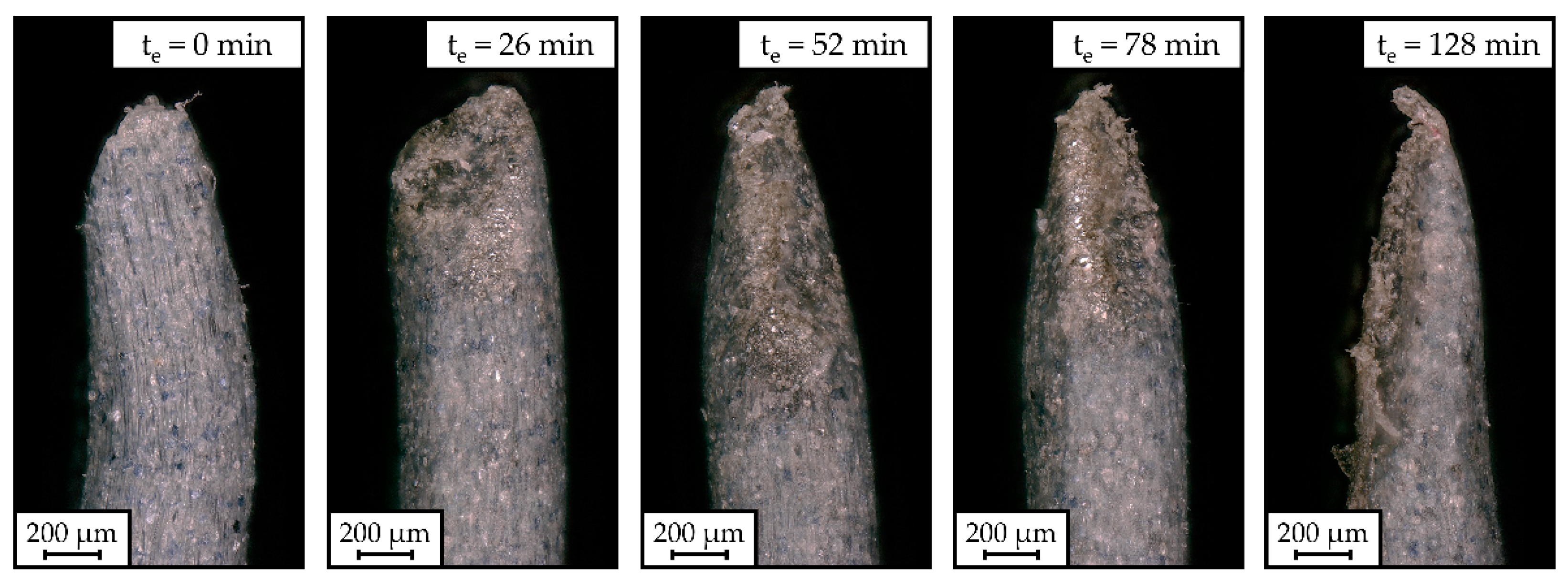
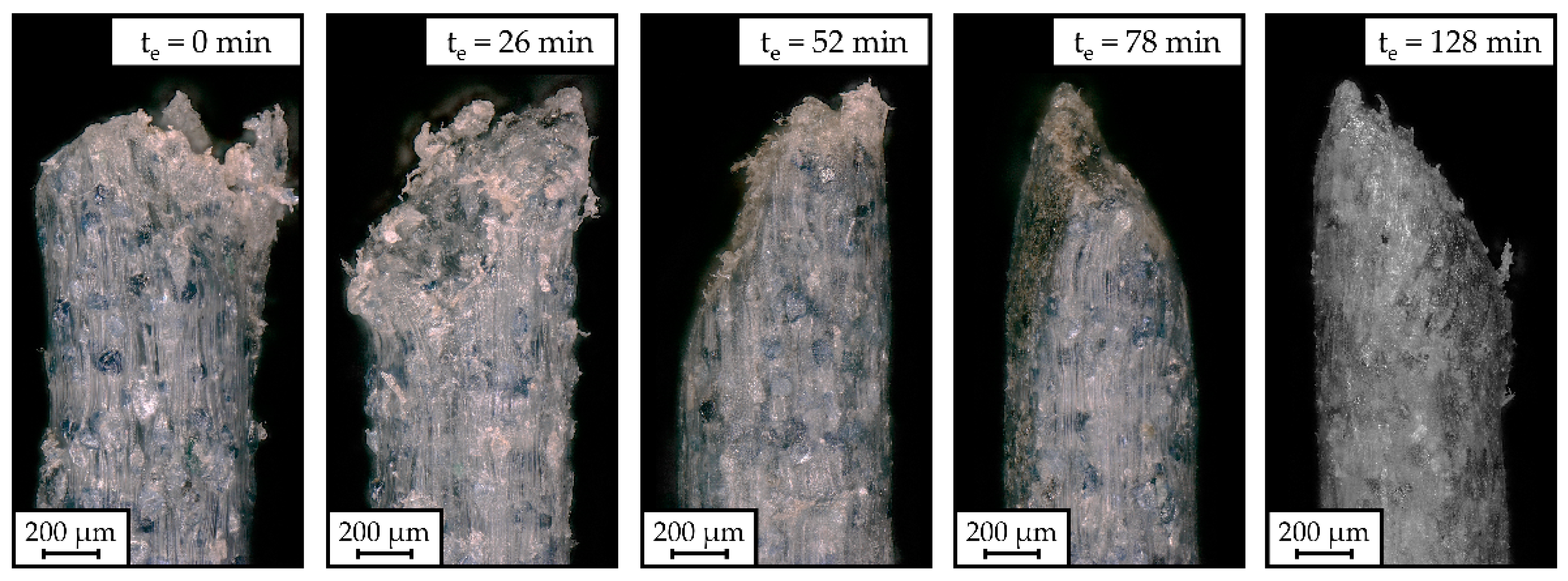
To qualitatively assess the wear of the brush filaments on a microscopic level, microscopies of individual filaments were taken after different processing times. When looking at the microscopic images of the individual filaments (S320x0.60) in
Figure 7, it becomes clear that wear sets in rapidly and that the filament tips in particular are flattened after a short time. This correlates with the findings on the tool life of the S320x0.60 brushing tool. Consequently, there seems to be a direct correlation between the cutting ability of the filament tips and the removal rate of the entire brushing tool.
In summary, it can be stated that the basic assumption that better roughness results can be achieved with the finer-grained filament specification is true when the tool is new, but the wear behavior of the thinner filaments is so poor that a constant removal rate cannot be guaranteed for the machining of a sufficient number of gear gaps or even a complete gearwheel.
3.1.2. Brushing Tool Specification S240x0.75
For the test series with the tool specification S240x0.75, a defined initial roughness of
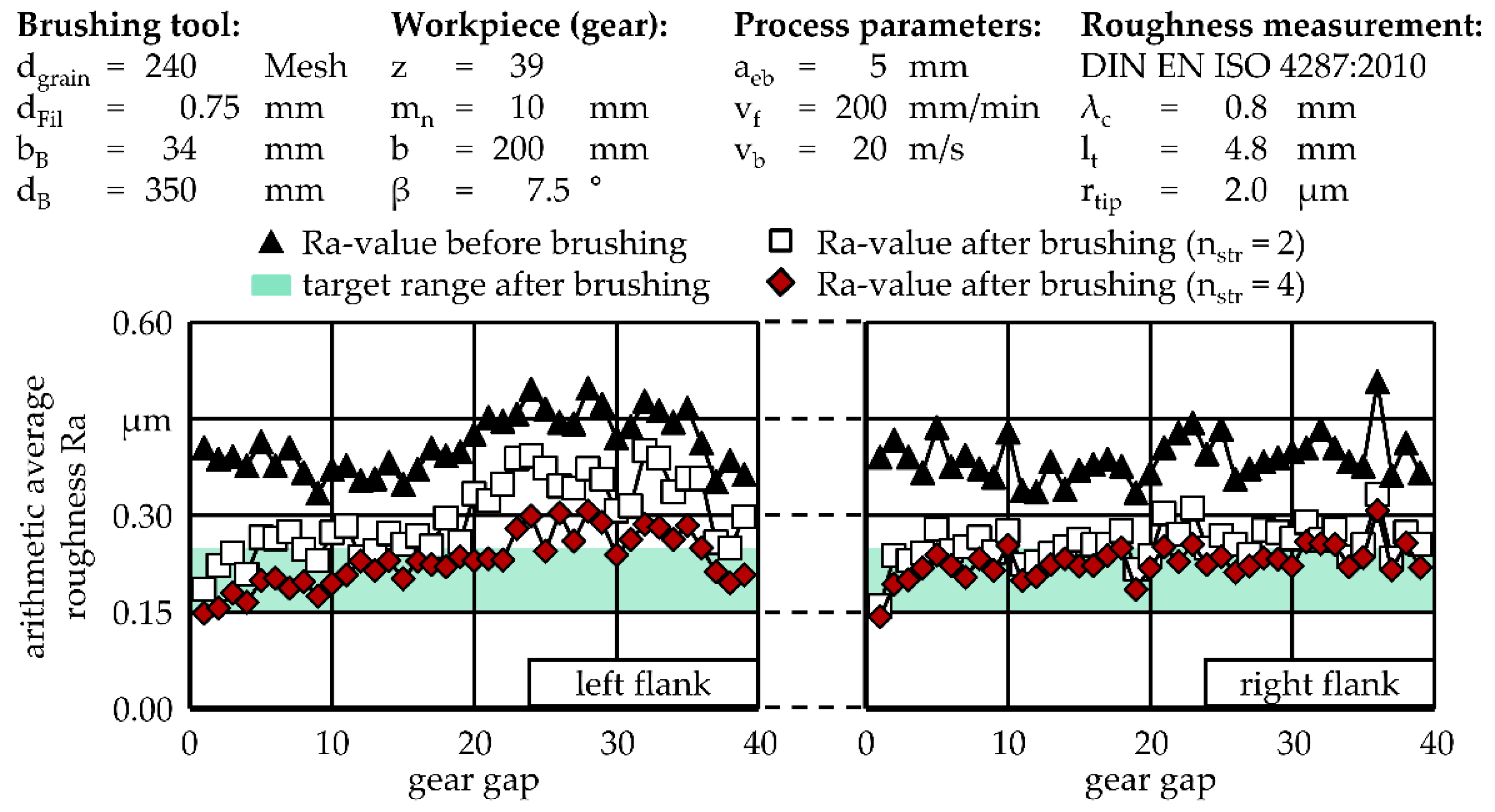
= 0.40 µm with a standard deviation of σ = 0.032 µm was generated, although there was a slightly higher deviation on the left tooth flank between the gaps 20 and 37. After brushing with two strokes per tooth gap, the flanks had an average roughness of
= 0.28 µm with a standard deviation of σ = 0.038 µm,
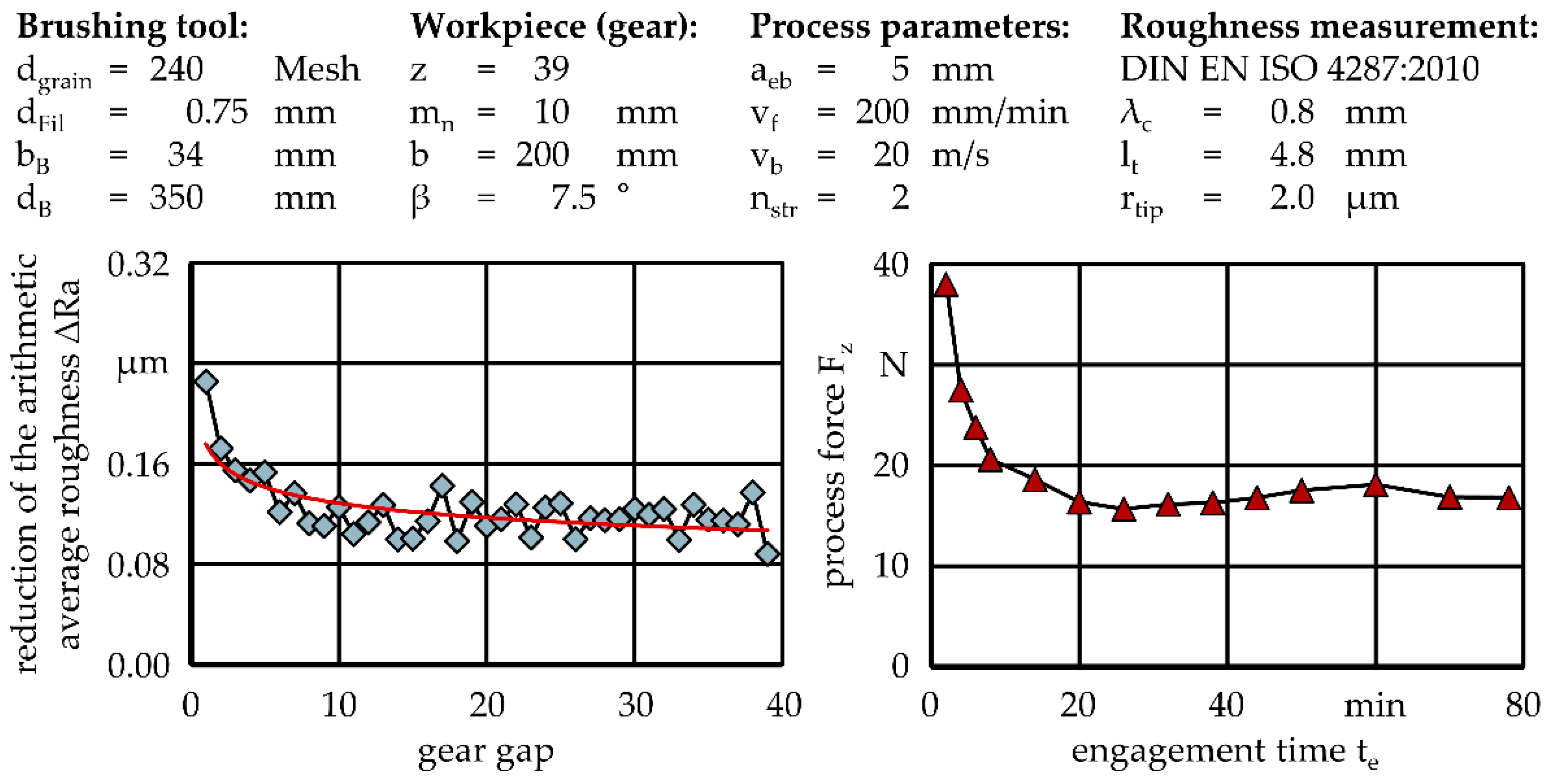
Figure 8. Similar to the test series with the brush specification S320x0.60 an initial phase could also be identified here,
Figure 9. However, it is considerably longer at t
e ≈ 20 min and the reduction in the arithmetic average roughness ΔRa decreases less steeply than with specification S320x0.60. After the initial phase, both the process force F
z and the change in the Ra-value remain constant, which leads to no indication of wear after an engagement time of t
e = 80 min.
Since the target range was not reached across the entire gearwheel, an additional brushing stroke was carried out to check whether it could be reached. As can also be seen in
Figure 8, the roughness was further reduced and an arithmetic average roughness of
= 0.23 µm was achieved across all gearwheel gaps. The standard deviation of σ = 0.029 µm is even lower than that of the initial state after grinding (σ = 0.032 µm). Based on the previously defined target range (Ra = 0.2 ± 0.05 µm), process capability indices of C
p = 0.58 and C
pK = 0.25 could be achieved. These are also higher than those of the upstream grinding process (C
p = 0.21 and C
pK = 0.21).
Since the changes in arithmetic average roughness ΔRa and process force F
z gave little indication of the wear of the brushing tool, another pre-ground gearwheel was finished with the same brush to determine the service life. The average change in the Ra-value when brushing the second gearwheel could no longer be achieved. The process force F
z also decreases after an engagement time of t
e = 80 min to 120 min. The brushing tool’s performance is noticeably limited compared to a new brush. Accordingly, the brush must be classified as worn after an engagement time of t
e ≈ 150 min. This assessment could also be supported by the microscopical examination of the filaments. As shown in
Figure 10, the structure of the filaments becomes smoother with increasing service time and the diameter decreases, which leads to a lower stiffness of the filaments.
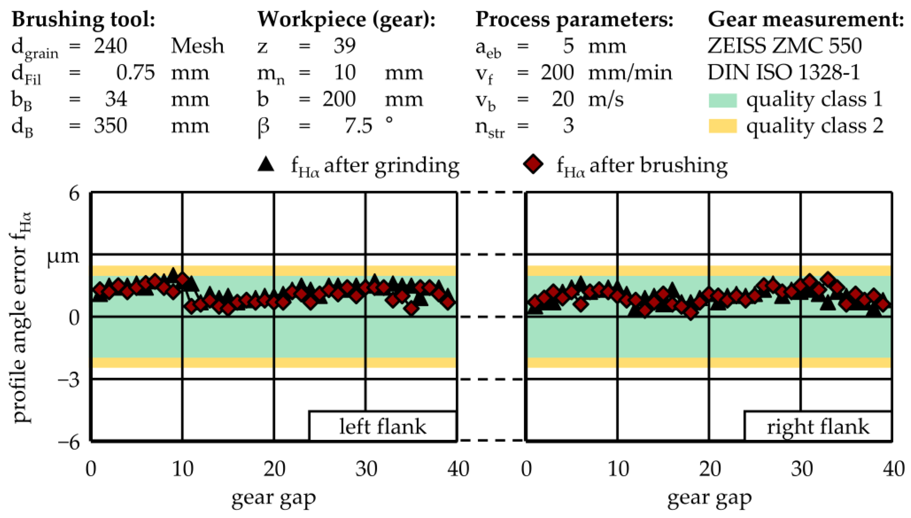
Another important aspect, in addition to improving the surface quality on the tooth flanks, is maintaining the geometrical quality of the gearing. Based on the profile angle error f
Hα before and after brushing, it could be shown that the brushing process has no negative influence on the macro-geometry of the gearwheel
Figure 11.
3.1.3. Influence of the Initial Surface Roughness
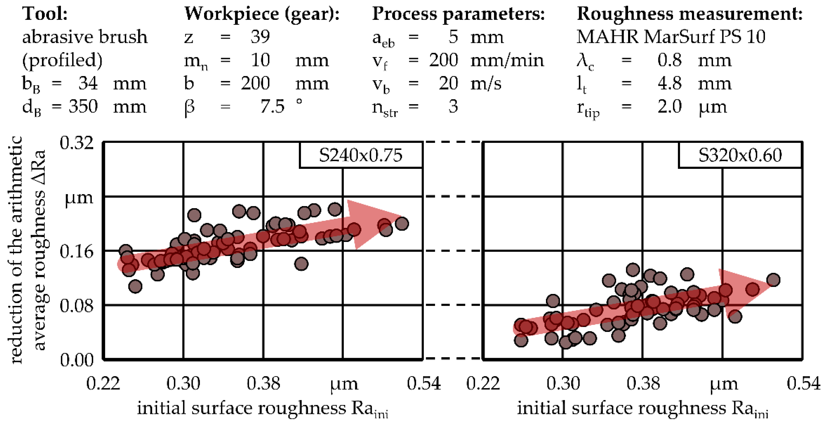
Finally, the influence of the initial surface roughness Ra
ini after grinding on the work result after the brushing process was considered. For this purpose, the reduction in surface roughness ΔRa was plotted against the associated initial roughness Ra
ini for both tool specifications,
Figure 12. Only the process points in the stationary range and with the same process parameters were considered in order to compare the two brushes and the correlation between the initial roughness Ra
ini and the change in the arithmetic average roughness ΔRa. It can be observed that the reduction the surface roughness ΔRa is greater for larger initial roughness values Ra
ini. This effect is equally pronounced for both tools, which means that differences in surface roughness are leveled out across the entire gearwheel after grinding. However, this adjustment is not strong enough to fully compensate for large deviations. Accordingly, the surface quality created by the grinding process has a significant impact on the absolute end result in terms of roughness parameters after the brushing process.
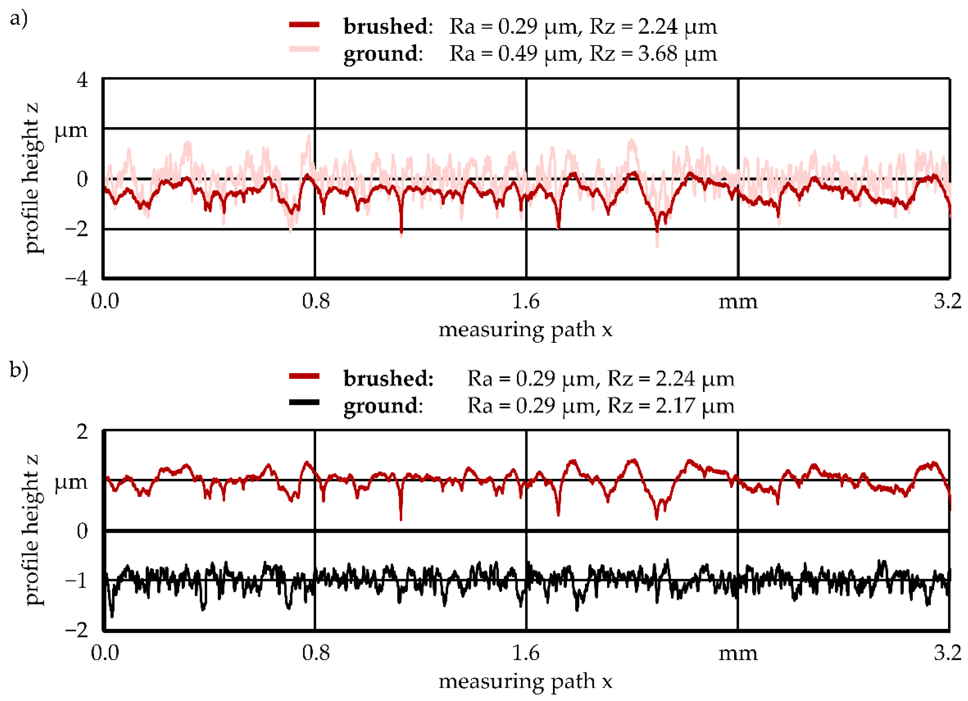
Furthermore, this connection makes it clear that removing the roughness peaks using abrasive brushing tools is easier than smoothing the core area of the roughness profile.
Figure 13a shows the roughness profiles of the same surface, initially after grinding, overlaid with the brushed result. It can be observed that the roughness peaks have been completely removed while the grinding grooves remain. The macro-roughness is therefore largely retained, whereas the micro-roughness is completely smoothed out by the brushing process. This finding explains the influence of the initial roughness on the absolute roughness parameters after brushing.
Figure 13b shows the roughness profile of the brushed tooth flank compared to a ground surface, which has almost the same roughness parameters. The qualitative consideration of these two roughness plots makes it clear how difficult it is to evaluate a brushed surface using metric roughness parameters. In order to determine the influence of the qualitative change in the roughness profile due to the brushing process on the service life and the operational behavior of the gearing, further investigations with brushed workpieces must be carried out.
3.2. Machine-Integrated Conditioning Technology
To be able to profile new brushes as well as restore the performance of worn brushing tools, a technology should be developed with which the filament tips, to which the main part of the microscopic wear was attributed, can be trimmed. Similar to the dressing of grinding wheels, new and cuttable abrasive grains are to be exposed in the area of the tool that is engaged with the workpiece surface. In addition, the possibility should be given to profile standard round brushes as desired and according to the respective toothing geometry. For this purpose, a design had to be developed that could be integrated into the grinding machine to ensure a flexible conditioning process.
3.2.1. Concept, Design, and Implementation
In cooperation with the grinding machine manufacturer KAPP NILES a device was designed and manufactured that makes it possible to implement the concept, which is illustrated schematically in
Figure 14, and to integrate it into the grinding machine.
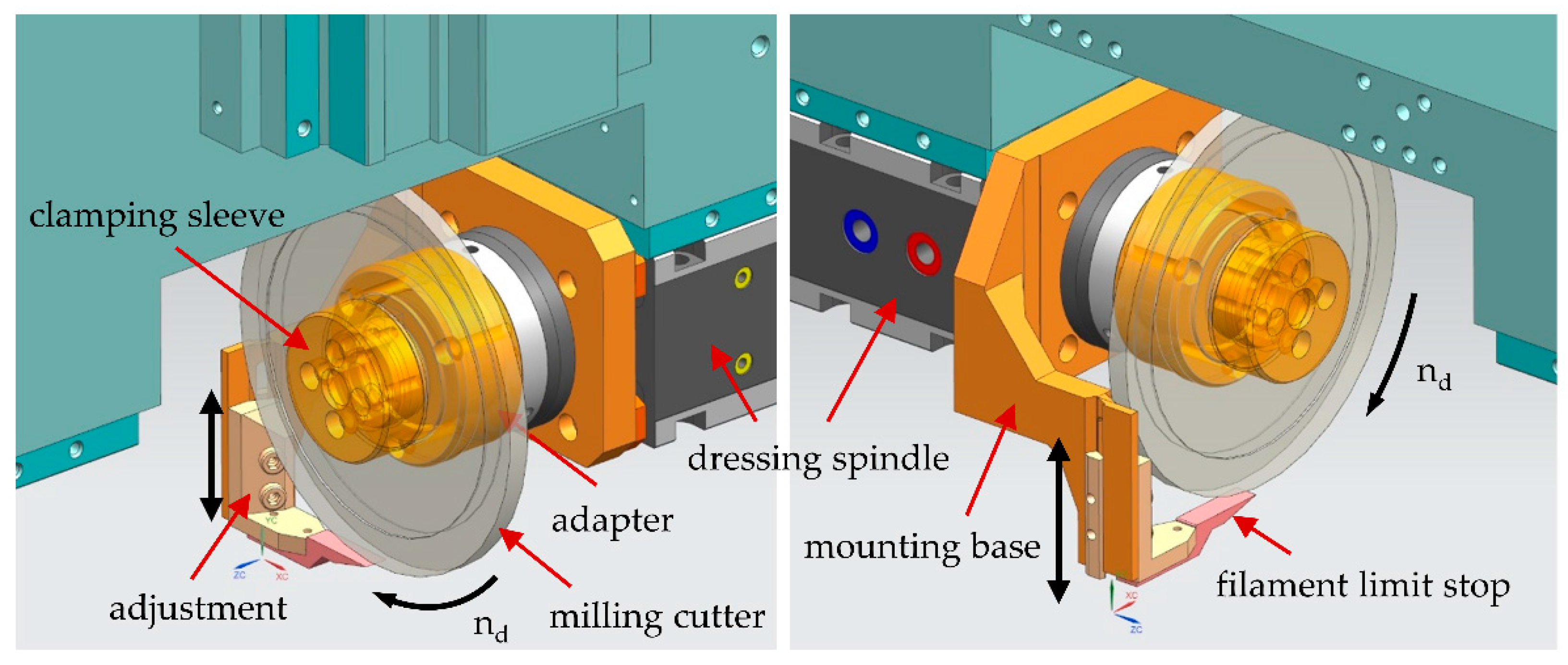
Figure 15 shows the front and rear views of the conditioning device as a complete CAD model. The setup consists of six individual parts. The mounting base is attached to the machine housing via the dressing spindle and is used to hold the filament stop by means of a support arm which is installed behind the dressing tool. Due to the fact that the adjustment connection can be moved vertically, it is possible to set the size of the cutting gap individually. The function of the cutting gap is shown in the schematic diagram of the separating mechanism in
Figure 14b. The optimized width of this gap was part of the investigations and therefore it was necessary that this could be adjusted manually. A disc milling cutter with 12 cutting edges and a width of 10 mm was selected as dressing tool. To ensure easy use for SMEs, an adapter was designed to adapt the mounting diameter to the smaller bore diameter of a standard milling cutter. The tool was then mounted on the spindle with a clamping sleeve. Indexable inserts reinforced with PCD were used to ensure that the cutting edges of the side milling cutter do not wear too quickly due to the abrasive effect of the brush filaments. Inserts with a rake angle of γ = 5° were selected for the highest possible cutting ability. In addition, the filament stop, which was designed to prevent the filaments from being deflected by the milling cutter, has also been fitted with an insert for indexable inserts. This has the advantage that they can be replaced quickly and easily when the edges are worn, thus guaranteeing a cuttable edge on both sides when cutting off the filament.
3.2.2. Process Parameters and Application
After the manufacturing and implementation of the designed solution, process parameters were determined. First, the size of the cutting gap bc, as well as the speeds of the brush spindle nb and the dressing spindle nd, were considered. For the width of the cutting gap bc, it was quickly determined that the smallest possible gap between the cutting edges of the side milling cutter and the filament stop leads to the best results. Since the gap is adjusted manually, the gap size is bc ≈ 0.5 mm. It was also discovered that the slower the brushing tool rotates, the better the result becomes. The lowest speed of the main spindle is limited to nmin = 50 1/min. To guarantee that the brush rotates at a constant speed when engaged, the speed was set to nb = 55 1/min. The speed of the dressing tool was then varied between nd = 800 1/min and nd = 2500 1/min. A speed of nd = 2500 1/min proved to be effective based on the removed filament volume per dressing cycle. With these selected setting parameters and a dressing feed rate of vfd = 10 mm/min, a brush from the previous test series could be evenly dressed in two cycles. The dressing infeed could be adjusted in fine increments with at least aed = 1 mm, which makes it possible to only trim the filament tips. The maximum infeed could not be clearly determined, but good dressing results could still be achieved with an infeed of aed = 3 mm. This can be advantageous for the quick profiling of standard round brushes.
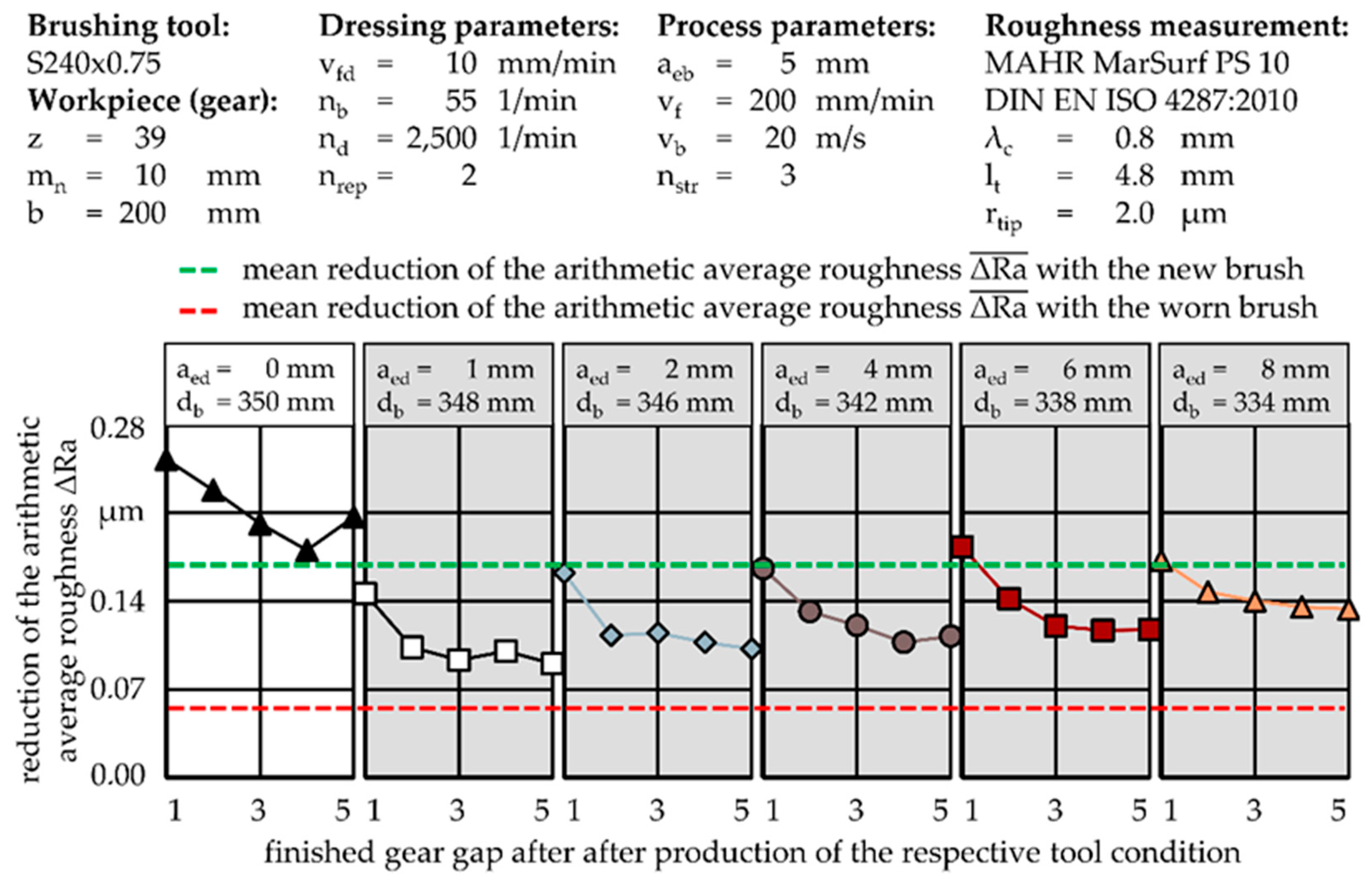
After the dressing parameters were determined, it was investigated to which extent the performance of a worn brushing tool could be restored by trimming the filament tips. For this purpose, a worn brush (S240x0.75) was dressed in iterative steps. After the respective dressing infeeds of a
ed = 1 mm to 8 mm, five gaps of a ground gearwheel (z = 39, m
n = 10 mm, Ra
ini ≅ 0.4 µm) were finished with the dressed brush. As shown in
Figure 16, the reduction in the roughness ΔRa could already be improved with a dressing infeed of a
ed = 1 mm in comparison to the mean reduction in the arithmetic average roughness
of the worn-out brush. However, the level of the average reduction
of the new brush could not be reached again. The linear relationship between the increased change in the arithmetic average roughness ΔRa and the dressing infeed a
ed is due to the increasing stiffness of the shorter filaments.
In summary, it can be stated that the cutting performance of a new brush could not be fully restored due to the reduced stiffness of the filaments. However, it is basically possible to dress worn brushing tools and to improve the removal rate compared to the worn condition by shortening the filament tips. In addition, the developed technology can be used to profile standard round brushes flexibly in the grinding machine according to the respective application.
4. Conclusions
The main goal of the research was to investigate the industrial feasibility of a finishing process for gear flanks using abrasive brushing tools to improve surface quality. Firstly, the process reliability and the tool life were determined using tests with two different brush specifications on reference workpieces with a normal module of mn = 10 mm. The influence of the initial condition of the ground gearwheels was also considered. It was shown that the brushing tool specification S240x0.75 is suitable for finishing a complete gearwheel and is therefore suitable for industrial use due to its significantly better wear behavior compared to the other investigated tool specification S320x0.60.
Besides, the significance of the initial state of the ground gear flanks for the absolute achievable roughness became clear. By using abrasive brushing tools, it is possible to remove the roughness peaks after a relatively short processing time and to achieve a process-reliable reduction of the arithmetic average roughness of ΔRa ≈ 0.2 µm. At the same time, the grinding marks, which are assumed to have a positive effect on the transport of the gear oil, remain intact. Nevertheless, the standard deviation of the target roughness across the entire gearwheel was lower than that of the initial roughness after grinding, showing that the brushing process has a positive influence on the scattering of the surface quality across the entire gearwheel.
Furthermore, it could be confirmed that brushing has no significant, not to mention negative, influence on the macro-geometry of the gearwheel. Due to the simple setup of the process, a high degree of flexibility and a large range of use cases are guaranteed in industrial applications, especially for SME. Another positive side effect that occurs when finishing gearwheels with abrasive brushes is the rounding of the edges on the end faces. By using this secondary effect of the brushing process, another process step that is often completed by hand could be substituted.
Another goal was to find a solution for machine-integrated dressing and profiling of the brushing tools. For this purpose, a concept was developed in cooperation with KAPP NILES, which was then implemented and integrated into the grinding machine. A disc milling cutter was used as a dressing tool and process parameters could be determined with which the conditioning process works as designed and the brush filaments can be trimmed with any contour and a wide range of infeed (aed = 1 mm to 3 mm). Restoring the performance of a worn brush is partially possible. By cutting off the worn filament tips, the brushing performance can be improved compared to the worn tool condition, but it was not possible to completely restore the performance of a new tool. Furthermore, a linear relationship between the increasing stiffness of the filaments, which results from shortening, and the improvement of the surface quality could be determined. In addition to the dressing of worn brushes, it is possible to profile standard round brushing tools, which create the possibility of flexibly adjusting the process to any given gear geometry. Due to the detailed documentation, the developed application can be adopted easily and used immediately.
Overall, it can be stated that the use of brushing tools for the machine-integrated finishing of gear flanks could become an alternative to the methods currently used in the industry. The greatest advantage of the process, especially compared to mass finishing, is that the workpiece does not need to be unclamped from the grinding machine for the finishing process and that the use of active chemicals is not necessary. For these reasons, the process has great potential, especially for SMEs. In particular, there is still room for improvement in the design of brushing tools, which could lead to an even higher productivity. Additionally, the operational behavior of brushed gearwheels considering the bearing strength and acoustical emission must be examined and compared with workpieces finished using other processes to investigate the effect of the characteristic roughness profile created by the brushing process.
Author Contributions
Conceptualization, B.G. and E.U.; methodology, B.G.; formal analysis, B.G.; investigation, B.G.; resources, B.G.; data curation, B.G.; writing—original draft preparation, B.G.; writing—review and editing, E.U.; visualization, B.G.; supervision, E.U.; project administration, E.U.; funding acquisition, E.U. All authors have read and agreed to the published version of the manuscript.
Funding
This research was funded by the Federal Ministry for Economic Affairs and Energy via the AiF as part of the program for the promotion of joint industrial research (IGF) within the scope of the project “Bürsten von Verzahnungen zur Verbesserung der Oberflächenqualität”, project number 21015 N.
Institutional Review Board Statement
Not applicable.
Informed Consent Statement
Not applicable.
Data Availability Statement
Not applicable.
Acknowledgments
The authors kindly thank Kapp Niles GmbH & Co. KG, Coburg, Germany, for support in the design and the integration of the conditioning technology.
Conflicts of Interest
The authors declare no conflict of interest.
References
- Leistungssteigerung der Windkraftanlagen—Größenwachstum von Windenergieanlagen. Bundesverband für Windenergie. Available online: www.wind-energie.de (accessed on 1 December 2022).
- Tobie, T.; Koller, P. Steigerung der Zahnflankentragfähigkeit Durch Kombination von Stahlbehandlung und Finishingprozess (FVA Nr. 521 I), Forschungsheft Nr. 957. 2010. [Google Scholar]
- Kapp, M. Hartfeinbearbeitete Antriebskomponenten zur Steigerung der Energieeffizienz in Antrieben. In Proceedings of the des XIII Internationalen Produktionstechnischen Praktikum, Berlin, Germany, 4–5 October 2010. [Google Scholar]
- Niskanen, P.; Manesh, A. Reducing wear with superfinish technology. AMPTIAC Q. 2003, 7, 3–9. [Google Scholar]
- Schwienbacher, S. Einfluss von Schleifbrand auf die Flankentragfähigkeit Einsatzgehärteter Zahnräder. Ph.D. Thesis, Technische Universität München, München, Germany, 2008. [Google Scholar]
- Hohle, A.C. Auswirkungen von Rauheit, Oberflächenstruktur und Fertigungsabweichung auf das Lauf- und Geräuschverhalten Hartfeinbearbeiteter Hochüberdeckender Zylinderräder. Ph.D. Thesis, Rheinisch-Westfälische Technische Hochschule Aachen, Aachen, Germany, 2002. [Google Scholar]
- Otmar, A.; Tröbst, S. Untersuchungen von Zahnradgeräuschen an schweren Nutzfahrzeugdieselmotoren mittels MAN-Geräuschindex. Motor-Aggregat-Akustik 2 2005, 51, 181–189. [Google Scholar]
- Klocke, F.; König, W. Schleifen, Honen, Läppen, 4th ed.; Springer: Berlin, Germany, 2005; pp. 427–431. [Google Scholar]
- Rösler Oberflächentechnik GmbH. Gleitschliffanlage für Superfinishing—Die Spitzen glätten. J. Oberflächentechnik 2008, 1, 48–49. [Google Scholar]
- Osro Super Finishing: Isotropic Super Finishing. Available online: https://www.osro-germany.de/ (accessed on 1 December 2022).
- Landenberger, D.; Steinhilper, R.; Rosemann, B. Verbesserung der Oberflächengüte durch Bürstspanen. VDI-Z 2007, 149, 67–69. [Google Scholar]
- Hochschild, L. Finishingbearbeitung Technischer Oberflächen aus Gehärtetem Stahl unter Verwendung von Rundbürsten mit Schleiffilamenten. Ph.D. Thesis, Technische Universität Berlin, Berlin, Germany, 2017. [Google Scholar]
- Uhlmann, E.; Bäcker, C.; Lypovka, P. Kinematische Modulation beim Zahnflanken-Profilschleifen von Zahnstangen. Wt Werkstattstech. Online 103 2013, 11/12, 875–881. [Google Scholar]
- Uhlmann, E.; Thalau, J. Bürsten von Verzahnungen zur Verbesserung der Oberflächenqualität (FVA Nr. 753 I), Forschungsheft Nr. 1291. 2018. [Google Scholar]
- DIN ISO 1328; Part 1. Zylinderräder—ISO-Toleranzsystem—Teil 1: Definitionen und Zulässige Werte für Abweichungen an Zahnflanken. Beuth: Berlin, Germany, 2018.
- DIN EN ISO 4287; Geometrische Produktspezifikation (GPS)—Oberflächenbeschaffenheit: Tastschnittverfahren—Benen nun gen, Definitionen und Kenngrößen der Oberflächenbeschaffenheit. Beuth: Berlin, Germany, 2010.
- Stango, R.J. Filamentary brushing tools for surface finishing applications. Met. Finish. 1999, 100, 83–92. [Google Scholar] [CrossRef]
- Rentschler, J.; Muckenfuß, G. Neue Anwendungsmöglichkeiten durch hochtemperaturbeständige Schleiffilamente in der Oberflächenbearbeitung. In Jahrbuch Schleifen, Honen, Läppen und Polieren; Vulkan-Verlag GmbH: Essen, Germany, 2013; pp. 387–403. [Google Scholar]
- Uhlmann, E.; Thalau, J. Finishing of Gear Wheels Using Abrasive Brushes. In Proceedings of the International Conference on Competitive Manufacturing, Stellenbosch, South Africa, 31 January–2 February 2019; pp. 324–330. [Google Scholar]
Figure 1.
Force measurement for gear machining/finishing.
Figure 1.
Force measurement for gear machining/finishing.
Figure 2.
Design of an abrasive brushing tool; (a) 3-D representation of a cast round brush with abrasive filaments; (b) Schematic cross-section of the brushing tool.
Figure 2.
Design of an abrasive brushing tool; (a) 3-D representation of a cast round brush with abrasive filaments; (b) Schematic cross-section of the brushing tool.
Figure 3.
Design drawing for the profiling of the brushing tools according to the gear gap.
Figure 3.
Design drawing for the profiling of the brushing tools according to the gear gap.
Figure 4.
Schematic representation of the process kinematics and parameters when brushing gearwheels; (a) 3-D view; (b) Sectional view.
Figure 4.
Schematic representation of the process kinematics and parameters when brushing gearwheels; (a) 3-D view; (b) Sectional view.
Figure 5.
Comparison of the arithmetic average roughness Ra before and after the brushing process for the test series with tool specification S320x0.60 and an initial roughness of Raini ≅ 0.4 µm.
Figure 5.
Comparison of the arithmetic average roughness Ra before and after the brushing process for the test series with tool specification S320x0.60 and an initial roughness of Raini ≅ 0.4 µm.
Figure 6.
Reduction in the arithmetic average roughness ΔRa and the correlating process force Fz for the test series with tool specification S320x0.60 and an initial roughness of Raini ≅ 0.4 µm.
Figure 6.
Reduction in the arithmetic average roughness ΔRa and the correlating process force Fz for the test series with tool specification S320x0.60 and an initial roughness of Raini ≅ 0.4 µm.
Figure 7.
Microscopies of single filaments (S320x0.60) after different process times.
Figure 7.
Microscopies of single filaments (S320x0.60) after different process times.
Figure 8.
Comparison of the arithmetic average roughness Ra before and after the brushing process for the test series with tool specification S240x0.75 and an initial roughness of Raini ≅ 0.4 µm.
Figure 8.
Comparison of the arithmetic average roughness Ra before and after the brushing process for the test series with tool specification S240x0.75 and an initial roughness of Raini ≅ 0.4 µm.
Figure 9.
Reduction in the arithmetic average roughness ΔRa and the correlating process force Fz for the test series with tool specification S240x0.75 and an initial roughness of Raini ≅ 0.4 µm.
Figure 9.
Reduction in the arithmetic average roughness ΔRa and the correlating process force Fz for the test series with tool specification S240x0.75 and an initial roughness of Raini ≅ 0.4 µm.
Figure 10.
Microscopies of single filaments (S240x0.75) after different process times.
Figure 10.
Microscopies of single filaments (S240x0.75) after different process times.
Figure 11.
Comparison of the profile angle error fHα before and after the brushing process.
Figure 11.
Comparison of the profile angle error fHα before and after the brushing process.
Figure 12.
Correlation of the reduction in the arithmetic average roughness ΔRa and the initial surface roughness Raini.
Figure 12.
Correlation of the reduction in the arithmetic average roughness ΔRa and the initial surface roughness Raini.
Figure 13.
Qualitative consideration of the roughness profiles of ground and brushed surfaces; (a) Comparison of the initial roughness and the brushed surface; (b) Comparison of a brushed and a ground surface with similar roughness parameters.
Figure 13.
Qualitative consideration of the roughness profiles of ground and brushed surfaces; (a) Comparison of the initial roughness and the brushed surface; (b) Comparison of a brushed and a ground surface with similar roughness parameters.
Figure 14.
Schematic illustration of the concept for machine-integrated conditioning of abrasive brushes; (a) 3-D representation of the design concept; (b) Illustration of the kinematics used to trim the brush filaments.
Figure 14.
Schematic illustration of the concept for machine-integrated conditioning of abrasive brushes; (a) 3-D representation of the design concept; (b) Illustration of the kinematics used to trim the brush filaments.
Figure 15.
Front and rear views of the CAD model of the conditioning device.
Figure 15.
Front and rear views of the CAD model of the conditioning device.
Figure 16.
Reduction in the arithmetic average roughness ΔRa using a dressed brush with different dressing infeeds aed compared to a new and worn-out brushing tool.
Figure 16.
Reduction in the arithmetic average roughness ΔRa using a dressed brush with different dressing infeeds aed compared to a new and worn-out brushing tool.
Table 1.
Measurement conditions for the detection of the surface roughness.
Table 1.
Measurement conditions for the detection of the surface roughness.
| Name | Symbol | Unit | Value |
|---|
| cut-off length | λc | mm | 0.8 |
| short-wave profile filter | λs | µm | 2.5 |
| sampling length | lt | mm | 4.8 |
| evaluation length | ln | mm | 4 |
| tip radius | rtip | µm | 2 |
| tip angle | rα | ° | 90 |
Table 2.
Specifications of the test gearwheel.
Table 2.
Specifications of the test gearwheel.
| Name | Symbol | Unit | Value |
|---|
| number of teeth | z | - | 39 |
| normal module | mn | µm | 10 |
| normal pressure angle | αn | ° | 20 |
| helix angle | β | ° | 7.5 |
| face width | b | mm | 200 |
Table 3.
Specification parameters of the brushing tools.
Table 3.
Specification parameters of the brushing tools.
| Designation | Abrasive
Grain | Filament
Diameter dFil | Max. Filament Length lFil | Brush
Diameter dB | Brush
Width bB |
|---|
| - | mesh | mm | mm | mm | mm |
| S240x0.75 | S240 | 0.75 | 51.5 | 350 | 34 |
| S320x0.60 | S320 | 0.60 | 51.5 | 350 | 34 |
Table 4.
Brushing process parameters.
Table 4.
Brushing process parameters.
| Brushing Infeed aeb | Feed Rate vf | Brushing Circum-ferential Speed vb | Number of Strokes per Gap nstr |
|---|
| mm | mm/min | m/s | - |
| 5 | 200 | 20 | 2 |
| Publisher’s Note: MDPI stays neutral with regard to jurisdictional claims in published maps and institutional affiliations. |
© 2022 by the authors. Licensee MDPI, Basel, Switzerland. This article is an open access article distributed under the terms and conditions of the Creative Commons Attribution (CC BY) license (https://creativecommons.org/licenses/by/4.0/).
