1. Introduction
Hydrogen is a high-potential alternative fuel source, which can help reduce the emission of greenhouse gases into the atmosphere. Using renewable energies, this element can be obtained through the electrolysis of water. Hydrogen fuel cells (FC) can rely on different principles and are found in various sizes; however, all of them generate electrical energy via an electrochemical reaction [
1]. Proton exchange membrane fuel cells (PEMFCs) have been developed for a wide span of power outputs, ranging from micro PEMFCs with 100 mW to applications requiring several kW [
2,
3,
4,
5].
Unlike in the automotive field, smaller portable applications currently on focus on the market-leading lithium-ion batteries and do not take fuel cell systems into account [
6]. Considering the energy density of batteries nowadays (usually between 50 and 200 kWh/kg), the added weight from the additional battery units poses a problem for most portable applications [
7]. A comparison of the energy and power density for different types of energy storage systems was shown by Julien et al. [
7]. Therefore, the search for lighter energy carriers could significantly impact the technology behind battery-powered machines. A weight reduction in the energy carriers could be realized by replacing traditional batteries with PEMFCs.
A proton exchange membrane fuel cell (PEMFC) requires a constant supply of fuel (i.e., hydrogen). A suitable option for this purpose is a metal hydride tank, which stores hydrogen at a low-pressure level compared to pressure tanks, in a dissolved state into metal particles. These may release or absorb the hydrogen gas depending on the pressure inside the tank. With respect to its discharge behavior, the tank presents a constant pressure for a wide range of hydrogen supply. Hence, a metal hydride tank shows an optimal behavior for the supply of hydrogen to smaller and portable PEMFCs, such as the tanks lower pressure level due to safety reasons.
Currently, there are mechanisms that demonstrate better energy and power density values when compared to lithium-ion batteries, which are the industry standard for most applications. This indicates that lithium-ion batteries could be substituted by alternative technologies, such as fuel cell systems. Especially for tasks with increased energy demands due to longer utilization periods, PEMFCs would be advantageous [
8]. The key characteristics highlighting PEMFCs’ superior functionality for portable applications are their lack of reliance on the power grid, their reliability, and their increased energy density when compared to batteries. PEMFC systems as energy carriers can have an energy density of about 850 Wh/kg. The benefits of PEMFC systems, when compared to classical battery systems, increase with an increasing operation time [
7,
8,
9].
A portable fuel cells performance is challenged when operating at low (<0 °C) and increased ambient temperatures (>40 °C). Current and power drop with lower temperatures, which leads to a decrease in efficiency [
10,
11,
12,
13]. With every succeeding subfreezing start-up, the current density can drop further due to permanent damage in the membrane caused by ice formations [
1,
12]. By electrically heating up a PEMFC stack, it will achieve higher temperatures significantly faster when compared to passive heating caused by its own heat losses [
14]. Therefore, the subfreezing start-up of PEMFCs sets a barrier towards its further commercialization [
15]. This characteristic trait is found to negatively affect many portable devices. Potential portable applications can be power generators, drone applications, or power tools. Unfortunately, in everyday environments, subfreezing temperatures are fairly common and at times unavoidable. As a result, it is vital to look for appropriate solutions allowing devices powered by a PEMFC to function under subfreezing temperatures.
Due to the weight and size constraints of portable machinery, the available space to construct a solution is quite limited. Different strategies have been proposed to enable the subfreezing start-up of a PEMFC [
16,
17,
18]. There are two common methods used for the subfreezing start-up of a PEMFC. The first method includes purging the device prior to shutting it down and humidifying it before start-up. This extracts the water inside the membrane, which results from the operation of the PEMFC. The second method heats up the device before start-up in order to reach temperatures above the freezing point of water [
12,
13,
14,
15,
19,
20]. However, the first method, which purges and humidifies the device, would require an additional subsystem. As this would require an adequate amount of space and add weight to the system, it would undermine the portable characteristics of the device. In addition, at subfreezing temperatures, this alone cannot reliably prevent the formation of ice, as there is no way to determine whether all water has been removed from the cell.
Many other patents and invention disclosures have solved the subfreezing start-up problem by circulating a previously heated liquid around the FC. This, however, is not suitable for portable applications, as this contradicts the weight and size restrictions [
21,
22,
23,
24,
25]. By reversing the polarity of the cell, a reverse current flow through the PEMFC generates heat. This may cause degradation within the cell after several uses [
15,
26,
27]. Therefore, this solution is not ideal for the subfreezing start-up of a PEMFC despite its simplicity as well as its low weight and volume.
Inserting a higher amount of hydrogen into the anode causes an exothermic reaction that heats the cathode [
28]. Another possibility is to keep the stack temperature in a specified range by using electrical heaters, in turn preventing ice formations [
29,
30]. Keeping the stack temperature in a specified range over a long period of time would require a great deal of energy, which is not suitable for portable applications. More simplistic solutions have been suggested where the stack has electrical heaters that raise the temperature only prior to the actual start-up [
31,
32]. Given that this system’s functionality adds minimal weight and volume to the device, it may be a suitable solution to heat the small PEMFCs during a subfreezing start-up. In addition, the hydrogen supply is highly dependent on the temperature and is critical for the PEMFCs operation. Therefore, the thermal management strategy for the hydrogen tank has to be considered in portable applications [
9].
Due to weight and size constraints of portable machinery, only a limited amount of energy can be used for the heating. The used heating strategy needs to provide enough heating power to achieve this heating process for the PEMFC. As a result, the energy storage has to provide enough energy for the strategy. The control strategy has to take into account the strict weight and size constraints that a portable device imposes. Therefore, the influence of ambient temperature on the heating strategy is especially relevant in portable applications. The ambient conditions influence the required energy, reliability, as well as efficiency of the PEMFC system; however, its effects under portable constraints are currently unknown.
A tradeoff between the heating strategies and portable constraints has to be considered to ensure a reliable operation. The goal of this study is therefore to investigate and validate heating strategies for environments in which portable FC are subjected to subfreezing temperatures.
2. Materials and Methods
In the following chapter, the experimental procedure is presented. This includes the control strategies and modeling, the simulations, the individual experiments, as well as the procedures used to collect the experimental data.
The prototype used for this study is a modified portable cordless screwdriver that is based on a Festool PDC 18/4. It was modified to function using a 20 W PEMFC stack and a small energy buffer. The energy buffer has a maximum power output of 900 W and a capacity of 43.3 kJ. This setup is used for all experiments conducted in this study as well as for the necessary parametrizations needed for the simulation models [
33]. This prototype is presented in detail in a preliminary study [
33].
2.1. Control Strategy and Study Design
Prior to start-up, when warming up the PEMFC at subfreezing ambient temperatures, potential ice formations in the cathode melts before the internal reaction begins. As a result, damage to the membrane can be avoided. This may also influence the power output and efficiency of the cell. Through the use of different sensors, temperatures and ice formations could be directly measured and/or detected within the cell. Unfortunately, due to the lack of space within the PEMFC membrane, these sensors cannot be included in the design. This leads to uncertainties, which cannot be solved by simulation or component tests. In order to investigate these uncertainties, testing the overall system is necessary.
Therefore, the ambient temperature (Ta) as the test case (TC) and the temperature at which the heater is turned off (THO) as the control strategy (CS) are investigated in this study. The ambient temperature Ta is varied in two test cases. Test case one (TC1) is a non-subfreezing start-up with Ta = 5 °C. Test case two (TC2) is a subfreezing start-up with Ta = −3 °C.
The heating is performed until a certain measured temperature in the PEMFC is reached. When the temperature is reached the first time, the heater is turned off. By varying the temperature at which the heater is turned off (
THO), the effect of the control strategies on the power output, efficiency, and reliability can be investigated. The PEMFC in this study has a nominal temperature is 50 °C, and this temperature was used for control strategy one (CS1) as
THO. Control strategy two (CS2) has a temperature
THO just over the freezing point of water, with
THO = 5 °C. This demonstrates whether the heating strategy is enough for a safe subfreezing start-up as well as how much energy is required for the different strategies to function properly. The four possible combinations of TC and CS are given in
Table 1. The four combinations are tested in this study by experiment and simulation.
The heaters controller, specifically for the hydrogen tank, may deliver the same output for all experiments carried out at temperatures 15 °C and 25 °C. This is justified by the steady hydrogen flow maintained throughout these tests. This temperature range was obtained from the study conducted by Kyoung et al. It allows the pressure output of the hydrogen tank to lie within a range that allows for normal operation of the PEMFC [
9].
The control strategy is made up of three parallel paths. It starts when the device is turned on. On the left side of
Figure 1, the state flow diagram for the hydrogen supply control strategy to the PEMFC membrane is shown. Here, the valve is only opened when the temperature of the FC is above 5 °C. When the temperature in the tests decreases and drops below 5 °C, the valve is closed to prevent permanent damage to the membrane. In the middle path, the control strategy for the FC heater is shown. The heating starts when the FC temperature is below
THO. Once
THO is reached for the first time, the start-up heating is completed, and the heater is turned off.
The right path in
Figure 1 shows the hysteresis controller for the metal hydride tank heater. The hysteresis controller keeps the tank temperature in a range between 15 °C and 25 °C. The tank heater, as well as the FC heater, are stopped by the left part if the FCs temperature drops below 5 °C, as the tests are completed there. The complete control strategy is shown in
Figure 1.
2.2. Mathematical Simulation Model
The model design is based on the physical components of the cordless screwdriver.
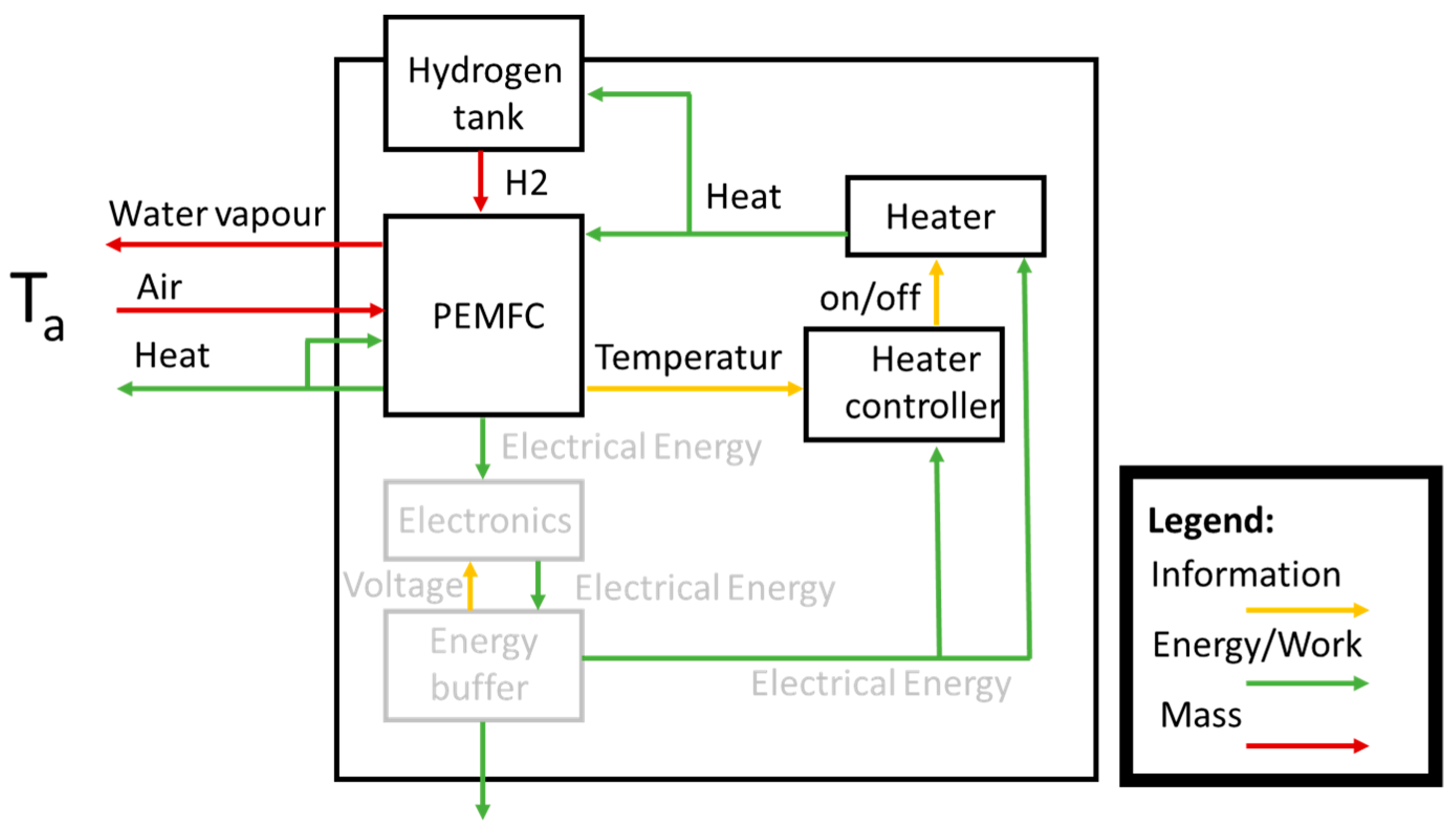
Figure 2 shows the structure of the proposed system, as well as the interaction between individual components. This design focuses on the system’s thermal behavior as well as the necessary components needed to apply the heating control strategy. The grey-colored blocks were not considered in the model. Although they belong to the power supply subsystem, they were out of the scope of this study.
The ambient temperature
Ta is considered the environmental parameter in this model. It is assumed that similar parameters have little to no influence on the system’s behavior. The thermal model used in this study takes two subsystems into account: the PEMFC and the hydrogen tank.
Figure 3 shows the thermal circuit for these subsystems. Here, the thermal masses are represented by ellipses, while heat transfers are represented by rectangles. The heaters are represented as triangles. The PEMFC and the hydrogen tank are thermally isolated from each other. The environment is assumed to be an ideal temperature source with constant temperature
Ta.
Both the PEMFC and hydrogen storage are modeled as thermal masses with the starting temperature
Ta. The thermal mass of the metal hydride tank is measured at 275 J/K. The thermal mass of the PEMFC is modelled with 81 J/K. Heat conduction, convection, and radiation are considered as well as heat exchange with fluids. The effect of the air between the hydrogen tank and the case is negligible. The PEMFCs heater has a heating power of 70 W, while the metal hydride tanks heater has a heating power of 30 W.
In our model, the heat exchanged between two points is described as the product of the heat conductivity
λA→B and the difference in temperature
T between them. As shown in Equation (1), both variables were in this case time-dependent. Alternatively, this can also be expressed as the summation of all heat exchange mechanisms applied to the different points of the heat transfer chain. All three heat exchange mechanisms were considered for the five heat transfer paths, represented as rectangles in
Figure 3. For the different heat transfer mechanisms, temperature-dependent coefficients were calculated. These were assumed to be constant throughout the simulation. The single coefficients were not validated by experiment, as this would require a complex experiment for each coefficient [
34]. The balance of absorbed/released energy by the reaction inside the PEMFC was calculated using the gravimetric flows
for both the incoming reactants and the outgoing products. The corresponding specific enthalpy values were calculated
hx, using the gas’s temperatures.
An electrical model of the PEMFC was implemented since its electrical output has the most significant influence on the power supply subsystem. It was modeled as a Thevenin’s equivalent circuit with a diode, as proposed by Njoya et al. [
35]. The PEMFC’s losses as well as the heating power of the heaters were calculated from its electrical model and the heaters, respectively. Equation (2) displays the mathematical definition of its output voltage
V. This depends on the open circuit voltage
VOC, the number of cells in the stack
N, the Tafel slope A of the voltage-current curve, the exchange current
iO, and its current
iFC respectively, as well as the response time
Td. Its open-circuit voltage
VOC was calculated, as shown in Equations (3), as the product of the voltage constant at nominal operation
KC and the Nernst voltage
En. The exchange current
iO, shown in Equation (4), is a function of the Boltzmann’s constant
k, the partial pressures of hydrogen
pH2 and oxygen
pO2, the ideal gas constant
R, the Planck’s constant
h, the activation energy barrier Δ
G, and the temperature of operation
T. Finally, Equation (5) shows that the Tafel slope
A is a function of the ideal gas constant
R, the temperature
T, and the charge transfer coefficient
α.
The used 20 W PEMFC stack at nominal operation delivers 7.8 V and 2.6 A. The nominal operating temperature range lies at 55 °C and the nominal ambient temperature range between 5 °C and 30 °C. This of course reinforces the argument for using heating strategies for a subfreezing start-up. The nominal hydrogen pressure lies between 0.45 and 0.55 bar depending on the storage temperature. This shows that the temperature of the hydrogen storage needs to be managed as well since it has an important impact on its pressure. It is worth noting that this PEMFC’s nominal efficiency is 40%.
The PEMFC had a power output depending on its temperature and electrical load. This demonstrates the importance of implementing heating strategies in order to generate the highest power output from the cell [
36]. The implemented model for the metal hydride hydrogen storage for the adsorption pressure of the metal hydride is based on Kyoung et al. [
9]. Equation (6) shows the outgoing flow from the tank
Qout in relation to the opening cross-section
Aout, the difference of pressure between the tank and the environment Δ
p, and the density of the gas
ρ.
The flow between devices was transported through plastic tubes and was assumed to be adiabatic. The amount of heat absorbed by the incoming gases from the PEMFC’s membrane was negligible for determining its temperature.
Table 2 shows the list of variables that were considered in the above-mentioned simulation. These variables were considered in the experiments as well.
The simulation model considered all relevant subsystems for the investigated thermal behavior. It also included some simplifications along the entire system that left out variables that had a negligible impact on the studied behavior. The model was implemented into Matlab Simulink. The goal of these simulations was to virtually test the required heating energy for the heaters of the PEMFC and hydrogen tank. The PEMFC’s temperature was evaluated in these simulations. These could then be related back to heating strategies aiding the subfreezing start-up of a PEMFC-powered portable device. This is achieved by using the XiL-approach (X-in-the-Lopp, Software-in-the-Loop SiL, Hardware-in-the-Loop HiL). This method is carried out by taking a component of a sub-system (HiL) or the algorithm of [
37] the heating strategy (SiL) and repeatedly testing its influence on the entire system, while slight changes are made with every iteration.
The simulation was carried out with the four tests listed in
Table 1. After that, experiments were carried out to take the PEMFC’s efficiency and therefore the reliability of the system into account. The experimental setup is further explained in the following sub-section.
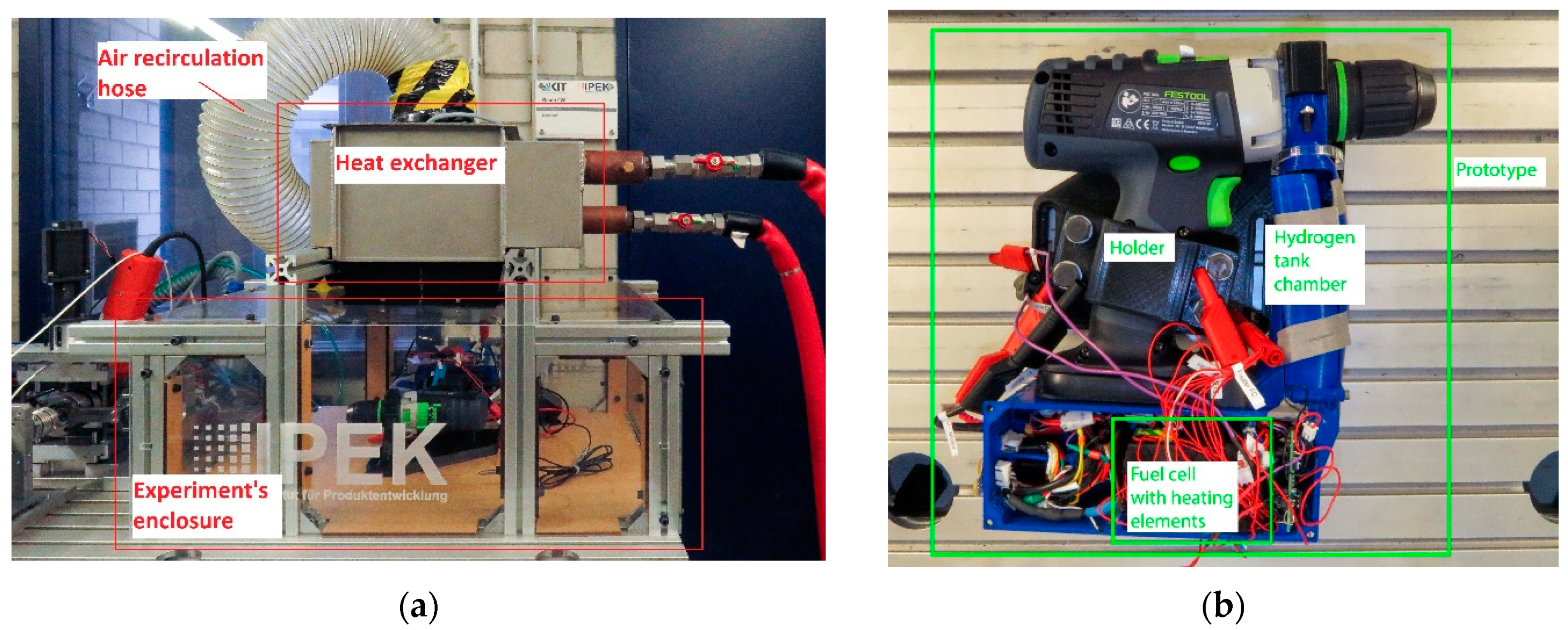
2.3. Test Bench for Experimental Investigation
Figure 4a shows the experimental setup. The prototype was held in place inside an enclosure where the ambient temperature
Ta was set to the desired value. The refrigeration unit Huber Unistat 425 was used to cool the air inside [
38]. The enclosure was made of 3 mm Plexiglas. The heat exchanger and ventilator were placed on top of the experiments enclosure. A near constant temperature within the enclosure replicated the ambient conditions typically found in real environmental conditions. The necessary sensors and controllers for the tests were attached to the prototype, as shown in
Figure 4b.
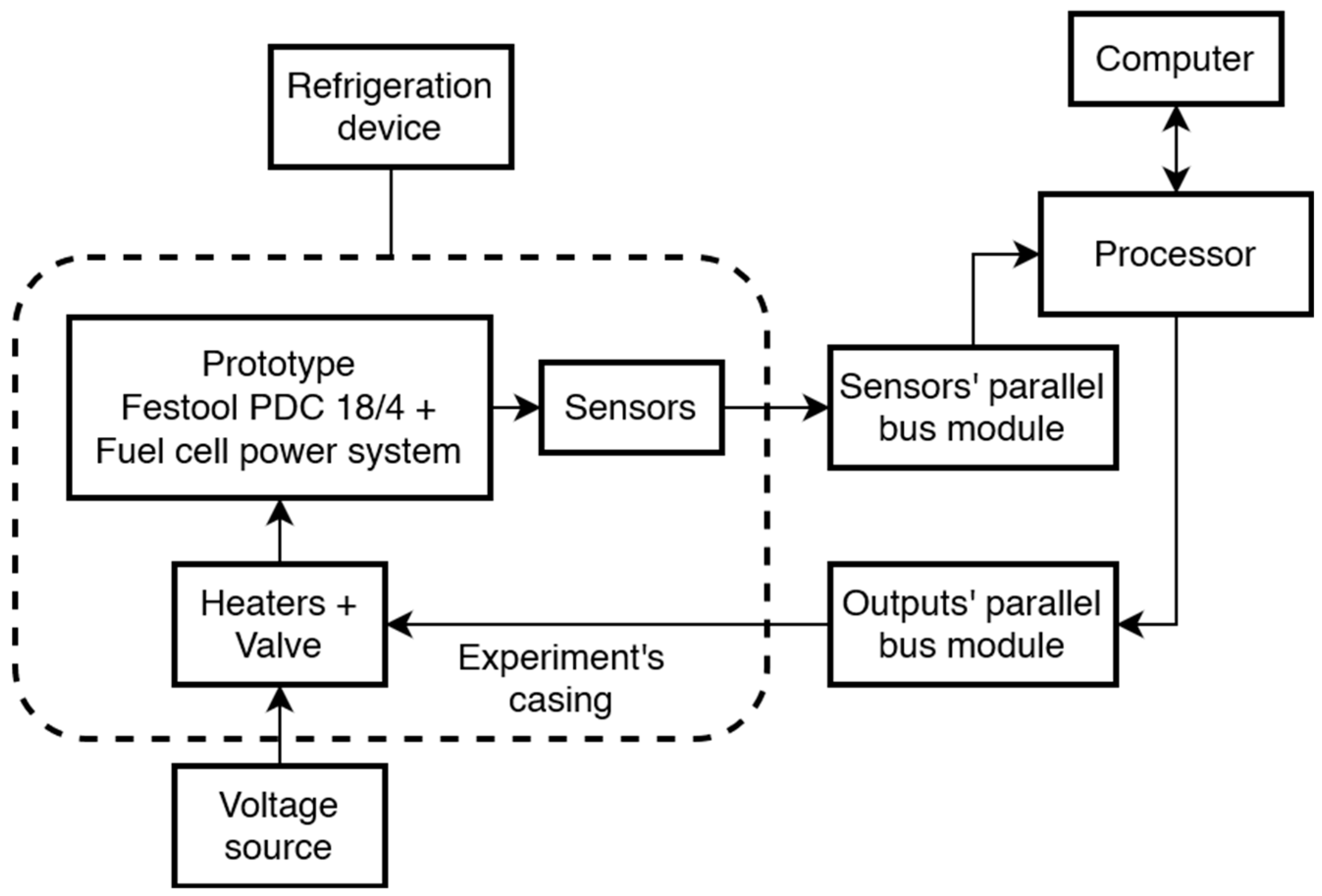
Figure 5 shows the scheme of the experimental design. The sensors given in
Table 3, heaters, and valve were attached to the prototype and connected to their respective control modules. This had a parallel bus interface that enabled the connection to the processor module. The processor module was connected via an Ethernet cable to the computer.
A ADwin-Pro II was used as a processor for control and data acquisition [
39]. The control algorithm was coded, compiled, and monitored using Matlab Simulink. In order to heat up the PEMFC and the hydrogen storage, heating foils were attached to them. Due to the limited space on the PEMFC and the hydrogen tank, multiple 10 W polyimide heating films were used for this study. The required heating energy for the control strategies is unknown. Therefore the heating foils were powered by a supply module EA PS9040-20T. It was set to provide a constant direct current voltage of 18 V, which represented the nominal voltage of the battery that was originally used in this prototype. The PEMFC’s output was connected to a resistor with a resistance of 3 Ω, which simulated the ideal load for its nominal working point (i.e., 7.8 V@2.6 A). PEMFC’s voltage and current are measured to rate the system’s power output. The mean efficiency is calculated by dividing the total power output of the PEMFC by the chemical energy of the hydrogen used.
The required start-up time and heating energy is evaluated for simulation and experiment in the four tests. The start-up is completed when the fuel cell heater and the metal hydride tank heater are both shut off. At this point, the desired temperature THO is reached, and the hydride tank is in the temperature window between 15 °C and 25 °C. The tank temperature can drop below 15 °C afterward as hydrogen is released to the PEMFC. Therefore, further heating energy is used to keep the metal hydride tank in the desired temperature window between 15 °C and 25 °C. Since the start-up is already completed, this energy is therefore not included in the evaluation of the start-up energy. By comparing the required heating time and energy between experiment and simulation, the validity of the simulation is evaluated. For this, the relative error between simulation and experiment is calculated for the start-up time and heating energy.
4. Discussion
The following section discusses the proposed heating control strategies in order to reliably operate a portable FC system in subfreezing temperatures. First, the effect to the required energy is discussed. Then, the influence of the control strategies on efficiency and reliability is analyzed.
4.1. Required Energy and Thermal Behaviour
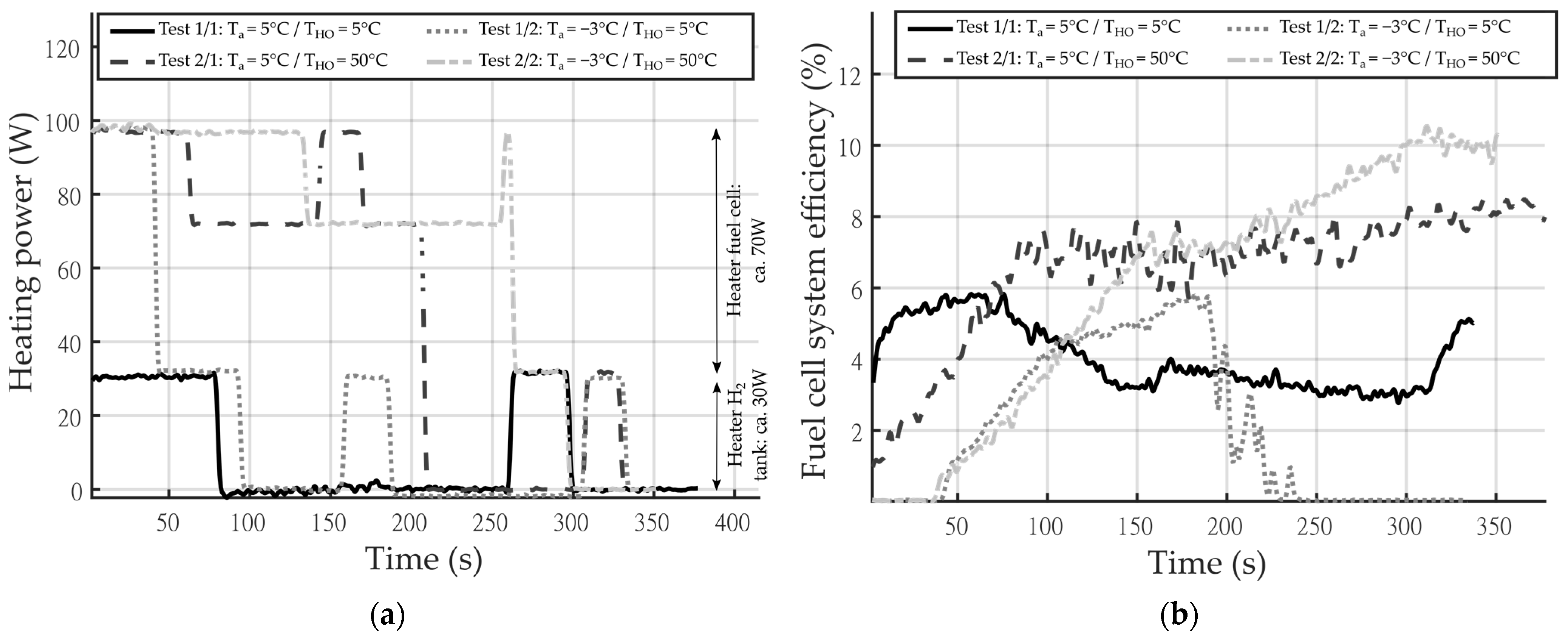
The variables measured in the experiments show the behavior that was expected from the simulative investigation. In addition, the experimental investigation allowed for the efficiency and reliability to be taken into account. The amount of power required by the heaters in all four tests was around 100 W (divided into approx. 30 W for the hydrogen tank’s heater and 70 W for the PEMFC heater). This can be delivered by commercially available energy buffers, which are required in such a system as buffer storage between the PEMFC and the motor electronics. The ambient temperature
Ta does influence the amount of time the heater is turned on. However, the temperature
Ta does have an impact on the required energy for the heaters. More heating energy is saved if the system is set at higher temperatures, and the heating strategies shut down the heaters at lower temperatures. This behavior was also shown by Oszcipok et al. Here, the amount of energy required for heating the PEMFC is highly dependent on the ambient temperature
Ta due to the heat transfer between the prototype and its surroundings [
14].
When looking at the required heating energy for the tests, there are deviations between the simulations and the experiments. However, the qualitative progression between simulation and experiment matches all four tests. Both investigations showed that the energy consumption is higher when both heaters are turned on. This behavior can be seen in
Figure 6 and
Figure 7b, where the three different slopes for the curve can be observed. The steepest slope corresponds to the case where both heaters were turned on. Next, the second steepest slope corresponds to the case where only the hydrogen tank’s heater was on. Finally, the flattest the three curves (ca. 0%) corresponds to the test where both heaters were turned off.
Test 1/1 showed the smallest deviation between simulation and experiment, calculated with the relative model error, for the start-up time. This test had the smallest start-up time with a positive relative model error. The relative model error of the required start-up heating energy is smallest in test 1/2. The relative model error for the start-up time is negative in test 1/1 and larger in its absolute value compared to test 1/1. Test 2/2 had the longest start-up time and showed the largest absolute relative model error for the required heating energy. Both model errors were negative in this test. Therefore, in the four tests, the absolute relative model error for the heating energy increased with an increasing start-up time. The relative model error turned with increasing starting time from positive to negative. This indicates that the heating losses were underestimated in the simulation. The heat coefficients and heat flows were assumed too low. The error adds up in the transmitted energy with increasing time. This leads to an underestimation of the required heating energy in the simulation. With an increasing start-up time, this leads to an increasing negative relative model error. The underestimated heating losses does not have a large effect in test 1/1 due to the small temperature difference between Ta and THO, therefore resulting in a small start-up time. With the larger temperature difference in the three other tests, the effect of this error increases and leads to a negative relative model error. As the relative model error for the heating energy in test 1/1 is quite small at 16.5%, it can be assumed that the thermal masses were modelled in the right range. The experimental determination of heat transfer coefficients would reduce the error in the simulations and make the results more valid.
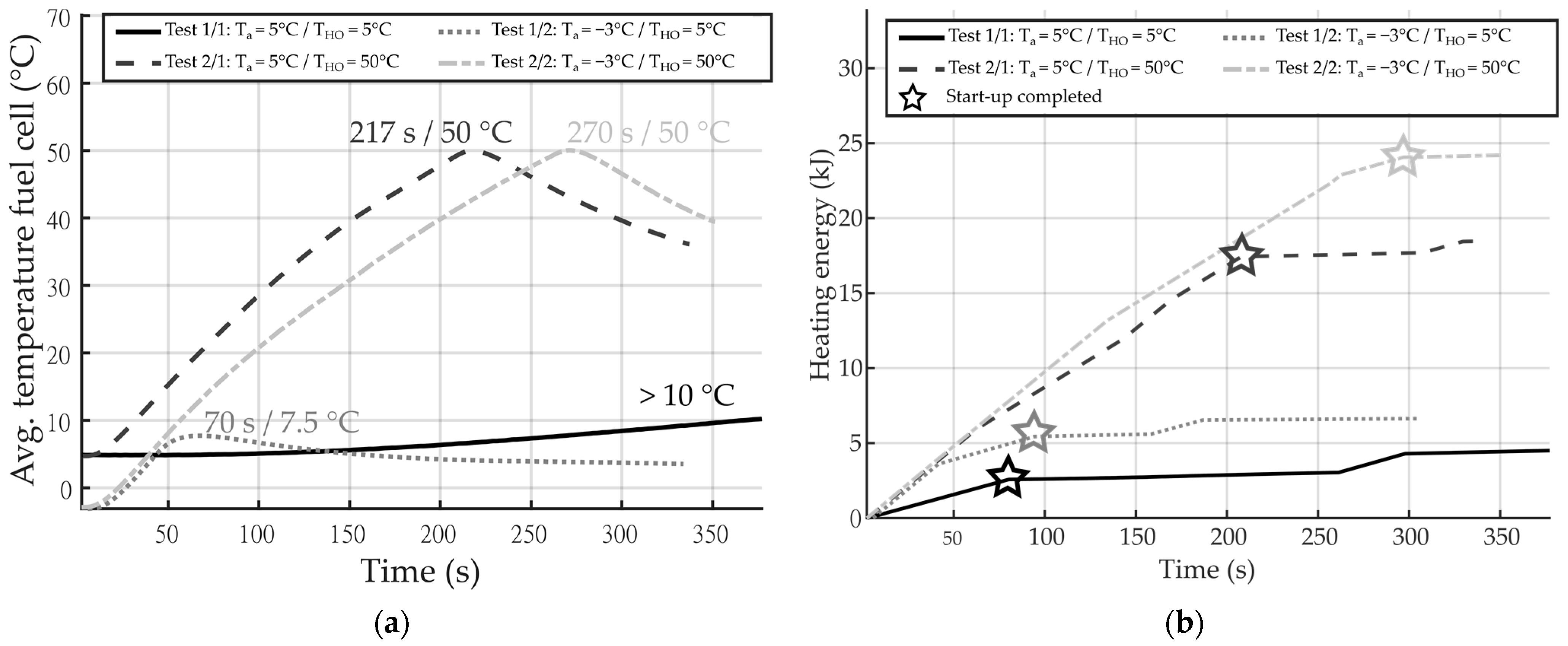
With the simulations, an energy buffer can be selected to carry out the heating strategies at an early development stage to enable frontloading. Furthermore, with the experiments, it can be determined if this energy buffer is sufficient for the device to function accordingly. The results shown in
Figure 7a indicate that for the worst-case scenario (i.e., test 2/2: subfreezing start-up and heating strategy up to the PEMFC’s nominal operating temperature), the amount of energy required from the energy buffer is ca. 24 kJ. This amount of energy can be provided by the energy buffer storage used in the prototype, which has a capacity of 43.3 kJ.
The ambient temperature
Ta has an impact on the required heating energy in the control strategy. The temperature at which the heaters are turned off,
THO, which is directly implemented in the control strategy, had a higher impact on the required energy, as seen in
Figure 7b, than the ambient temperature
Ta. This shows that portable fuel cell power systems are in principle capable of starting in subfreezing conditions. This also shows that the control strategy can have a higher impact on the energy requirements, and therefore on the design of the electrical system, compared to that of the ambient temperature.
The simulations carried out applied a handful of simplifications to the model. Notably, simplifications in the heat coefficient caused deviations in the results and are the main limitation for the simulations. Nevertheless, the tendencies presented by the simulation and tests are qualitative similar. As a result, this simulation model can be considered to assess how the system would behave in practice. With these simulations, it was possible to approximate how the PEMFC system would behave under different ambient temperatures and under different parameters for the heating strategies.
4.2. Influence of the Control Strategies on Efficiency and Reliability
As Datta et al. showed, the voltage and power output is lower for lower temperatures of the PEMFC. They also showed that the PEMFC’s voltage is at 50% of its rated voltage when it is operated at 10 °C [
19]. This phenomenon can be seen when looking at the efficiency of the fuel cell, which is highly dependent on its power output. The tests confirm this, as the results show that using a larger amount of heating energy during a cold start-up leads to the higher efficiency of the fuel cell system. However, since more energy is needed for heating, this reduces the overall efficiency in addition. For an optimal control strategy, the heating energy and the efficiency must be taken into account, which are in conflict with each other.
This is seen in
Figure 8b, as test 2/1 and test 2/2 reached a higher efficiency but also required a higher amount of energy. This is indicated in
Figure 7a. Another aspect is the tendency of the fuel cell’s temperature to stabilize itself after the heater has been turned off. This shows that after reaching a sufficiently high temperature, the fuel cell’s operation can produce enough heat to keep the device running even under a subfreezing ambient temperature
Ta. This phenomenon was also shown by Oszcipok et al. [
14]. This shows that using less heating energy for the fuel cell system could be sufficient for a reliable cold start-up. However, this is only the case if the ambient temperature
Ta is not too low, as this does not necessarily lead to better results. When comparing the temperature development over time between test 1/1 and test 1/2, it is seen that for ambient temperatures
Ta above 0 °C, the device is capable of heating itself. With this, it avoids damaging its membrane, and as a result, the heating strategies are not required to assure the reliability of the system under these conditions.
If the ambient temperature
Ta is too low or lies below 0 °C, it cannot heat itself up fast enough to avoid damage to the membrane. This is due to the fact its temperature would drop below the freezing point of water. If it is too cold, and the fuel cell is not sufficiently heated, the heat exchange with the environment can cause the heating strategy to shut down the fuel cell to prevent permanent damages in the membrane. This happens due to the temperature dropping to values too close to or below the freezing point of water (see
Figure 7a). Therefore, the goal of reducing the required heating energy is in conflict with optimizing the PEMFC’s output.
The phenomenon shown by Cho et al. and by Datta et al. demonstrated how the fuel cell suffers an irreversible performance decay during a subfreezing start-up. On the other hand, Chiang et al. showed that the power output of a fuel cell is reduced for lower temperatures. Both of these phenomena could be reduced and/or totally avoided [
12,
13,
19]. The results of this study could also help patents such as those proposed by Thompson et al. or Jang et al. by allowing these to be applied to a wider range of portable applications [
40,
41].
If the temperature of the fuel cell drops far enough, this would cause the water inside the cathode to begin to freeze. In turn, this would lead to an irreversible performance decay of the cell. Therefore, the heating strategies are vital for the reliable operation of the fuel cell under ambient temperatures Ta below 0 °C. For subfreezing temperatures, a more reliable control strategy is required, as supplying too little heating energy may cause permanent damage to the fuel cell. For ambient temperatures Ta above 0 °C, a more experimental control strategy to save heating energy can be implemented. For these reasons, the appropriate selection of a heating strategy for the cold start-up of a fuel cell system can significantly influence its efficiency and reliability. Due to reliability reasons, a differentiation in the control strategy between subfreezing and non-subfreezing through the heater shut off temperature is recommended.
5. Conclusions
The influence of the heating strategies during a cold start-up on a portable PEMFC system were investigated experimentally and through simulations. The necessary energy supply required to establish the efficiency and reliability of the fuel cell system were investigated.
To start, for a fuel cell system at an ambient temperature Ta of −3 °C, an energy buffer would have to deliver 25 kJ of energy to the heaters. Notably, this value can be obtained from traditional batteries. This energy buffer is strongly dependent on the control strategy, which is specified by the temperature at which the heater is turned off. It should be noted that the energy buffer impacts the efficiency of the fuel cell system. The ambient temperature, however, has a smaller impact on the required energy than the temperature at which the heater is turned off. The ambient temperature Ta impacts how fast the fuel cell will cool down after the heaters are shut off. The results also revealed that heating the fuel cell above 5 °C leads to a higher power output and efficiency of the fuel cell system.
When a higher efficiency of the fuel cell system is required, a greater energy supply is needed for the heating strategies. Using less heating energy (i.e., heating the PEMFC to a lower temperature) can save energy, but it may impact the reliable operation of the PEMFC system. It is proposed to adjust the control strategy regarding the ambient temperature whether it is subfreezing or non-subfreezing. For subfreezing ambient temperatures, a more reliable control strategy is required. This is to ensure its reliability, as subfreezing temperatures can cause permanent damage to the fuel cell membrane.
These findings help in dimensioning the energy buffer. The heat transfer coefficients are an uncertainty in the simulative design of such a system at an early development stage and should be validated with extra experiments. A miscalculation of the heat transfer coefficients can harm the reliability although a subfreezing start-up would be possible. Sufficient energy must be considered for the portable device to perform its function. The fuel cell loads the energy buffer in operation. Enough charge must be left in the energy buffer to heat up the fuel cell system the next time it is used. Therefore, the fuel cell can only switch off when this critical amount of energy is available in the energy buffer.
The findings with respect to the heating strategies help to improve reliability and efficiency during operation of a portable fuel cell system. Subfreezing temperatures were identified as a critical factor of the control strategy. Therefore, the distinction between subfreezing and non-subfreezing ambient temperatures has to be considered in the control strategy to ensure its reliability.


