Article

The Effect of Sensor Integration on the Load Carrying Capacity of Gears

1
Department of Mechanical Engineering, Politecnico di Milano, 20133 Milan, Italy
2
Institute of Machine Elements, Gear Research Centre (FZG), Technical University of Munich (TUM), 85748 Garching, Germany
*
Author to whom correspondence should be addressed.
Machines 2022, 10(10), 888; https://doi.org/10.3390/machines10100888
Submission received: 29 August 2022 / Revised: 23 September 2022 / Accepted: 27 September 2022 / Published: 2 October 2022

Abstract

:
Classical machine elements have been around for centuries, even millennia. However, the current advancement in Structural Health Monitoring (SHM), together with Condition Monitoring (CM), requires that machine elements should be upgraded from a not-simple object to an intelligent object, able to provide information about its working conditions to its surroundings, especially its health. However, the integration of electronics in a mechanical component may lead to a reduction in its load capacity since the component may need to be modified in order to accommodate them. This paper describes a case study, where, differently from other cases present in the literature, sensor integration has been developed under the gear teeth of an actual case-hardened helical gear pair to be used within an actual gearbox. This article has two different purposes. On the one hand, it aims to investigate the effect that component-level SHM/CM has on the gear load carrying capacity. On the other hand, it also aims to be of inspiration to the reader who wants to undertake the challenges of designing a sensor-integrated gear.

1. Introduction

Classical machine elements have been around for centuries, even millennia. For instance, mechanical gears can be traced back to the world-famous Antikythera mechanism [1]; one of the very first founders of modern gear theory can be identified in Euler, who in 1781, developed the mathematical formulation of the involute that later became the basis of the modern gear [2]. A similar case is that of bearings, which were studied by Leonardo da Vinci in his friction investigation [3]. However, despite being known and used for centuries, the increasing day-to-day industrial demand for a safe, reliable and lightweight mechanical system requires continuous research as a means to provide industry with a proper solution. Within this context, as a means to increase the system reliability (or at least reduce the occurrence of failure), the idea behind Structural Health Monitoring (SHM) and Condition Monitoring (CM) plays an important role [4], especially for rotating machinery [5].
Focusing on gearboxes, the current state of the art is to monitor the whole system using additional sensor equipment which has to be attached to the outside (e.g., [6,7,8,9,10,11,12,13,14,15,16,17]) rather than on a single mechanical component, since sensors are not located directly on the component. However, the advancements of SHM and CM are now moving towards the idea of a smart mechanical element that, apart from performing the task it has been designed for, is able to communicate information to the outside world about its working conditions, especially its health.
Within this context, the SPP2305 German priority program has been established in order to evaluate the development of smart machine elements [18] within 10 projects focused on different machine elements. From a mechanical point of view, the basic requirement for all these projects is that all the electronics have to be located inside the component, without requiring additional space. On the other hand, from an electrical point of view, the components have to communicate with the outside world without cabling, implying that each electronic system has to be self-powered and with a wireless data connection. Examples of smart components being investigated and developed within the program are screw, feather key, radial seals and, obviously, gears. Indeed, this paper presents the first results of the SIZA (Sensor-Integrated Gear, in German Sensorintegrierendes Zahnrad) project, in which prototypes of smart gears will be developed.
Indeed, current studies are now directing the field of condition monitoring to the mechanical component. Furthermore, it is possible to find applications of measurement systems for the SHM/CM of single machine elements. One of the early examples is the work of Holm-Hansen, B. and Gao, R. X [19,20,21,22,23,24,25,26,27], where the feasibility of smart bearings with micro-sensors is discussed from the point of view of both the bearing load carrying capacity and SHM/CM. The concepts of a smart bearing have also been discussed recently by Schirra, T. et al. [28,29]. Other examples for sensor integration in mechanical components include feather key [30], fasteners [31,32], ball screw (e.g., [33,34]) and die (seen as part of the overall stamping system) [35].
As a matter of fact, the idea of a smart gear has recently been proven to be a promising and feasible idea by Peters, J. [36,37,38] and by Sridhar, V. [39]. However, their studies were based on a spur gear geometry in an “open” gearbox (i.e., without housing), and the sensor board was directly attached to the gear body. Therefore, in order to overcome the problem of sensor integration, Binder, M. [40], focusing more on the sensor integration itself, proposed to use additive technologies as a means to embed sensors and electronics inside the gear body. Nevertheless, despite being advantageous for the sensor integration per se, additive-manufactured sensor-integrated gears present some technological difficulties. Firstly, very few data on gear load carrying capacity that can be used for additive-manufactured gear design are available in the literature (e.g., [41,42,43]). Secondly, the idea of embedding the sensor in the initial manufacturing phase implies that all electronic components must survive the mandatory heat treatment temperatures for high performance gears. As an alternative, the gear would not be heat treated, adopting a material with a low-load capacity with a detrimental effect on the gearbox dimensions.
Within this context, the implementation of SHM/CM within gears made of classical materials (e.g., case hardened steel) seems to be a rational idea. Indeed, those kinds of materials are well known for both their technological and load capacity points of view. Moreover, as the electronics will be fitted only after manufacturing, the aforementioned temperature problem is no longer an issue. However, this idea also implies that the gear body must undergo important modifications in order to accommodate all the electronics, and the effect that such modification will have on the gear load carrying capacity is unknown.
Here, in order to discuss the implementation of in-situ gear SHM/CM and the effect that sensor integration has on gears, an actual gearbox is adapted as a reference case. The aforementioned gearbox, and the related case-hardened helical gears, have already been developed and used in previous studies (e.g., [44,45,46,47,48]). Figure 1 shows the modification that the original gear geometry will undergo in order to accommodate all sensor boards inside the gear, underneath the teeth. Indeed, the gear body will be modified by creating the various ports adopting classical machine tools (e.g., lathe and milling machine). However, as the gear body is strongly changed by the sensor-integration requirements, the stress acting on the component also varies. Therefore, the load carrying capacity of the component is affected as well. Nevertheless, the said variation is not discussed in the literature.
Therefore, this article has two different purposes. On the one hand, it aims to investigate the effect that component-level SHM/CM will have on the gear load carrying capacity. On the other hand, thanks to the critical discussion about the design choices, as well as the adopted evaluation tools, it also aims to be of inspiration for the reader who wants to undertake the challenges of designing a sensor-integrated gear.

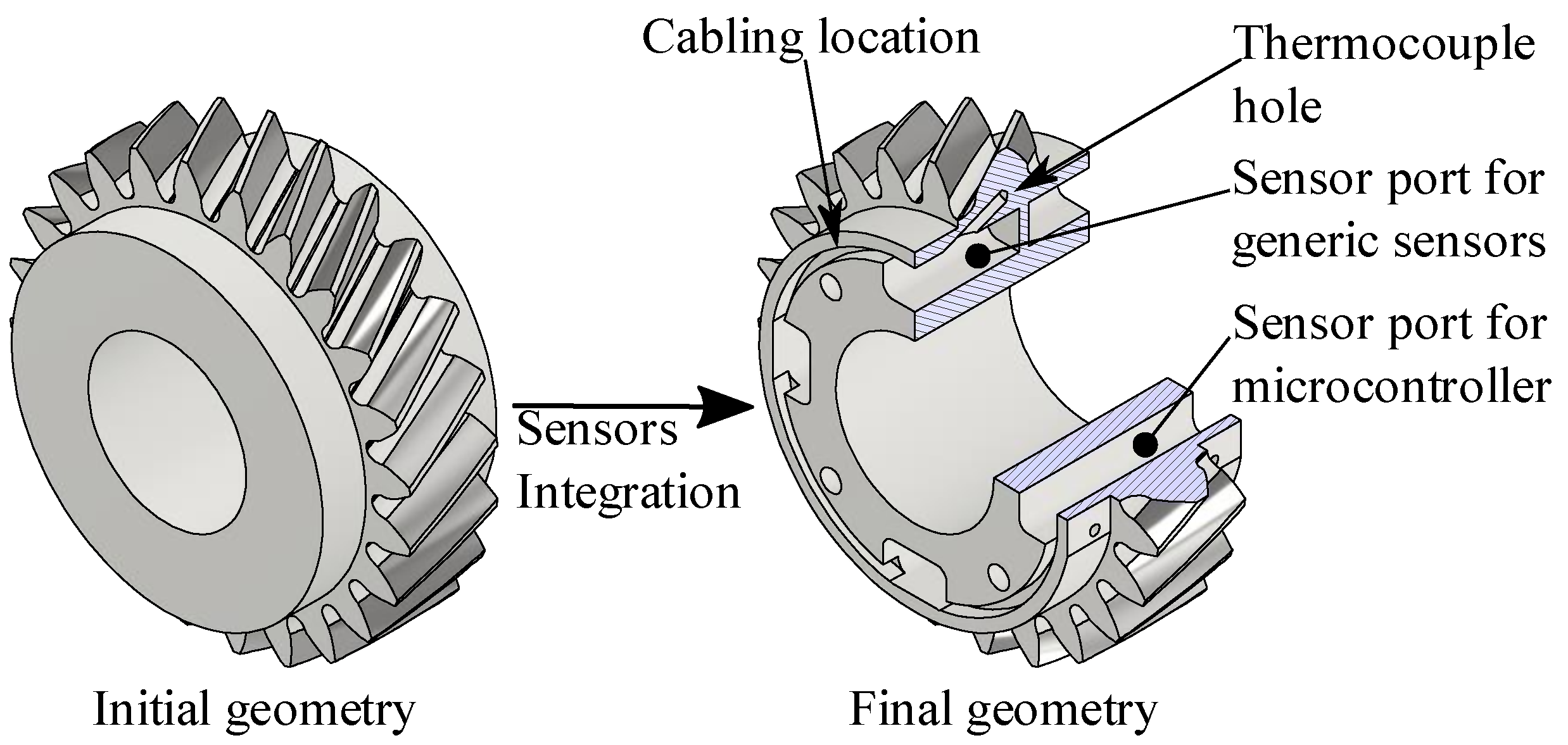
2. Definition of the Components

The gearbox that has been chosen in order to implement the component-level SHM/CM system is part of a back-to-back test rig with a center distance of 112.5 mm, whose typical maximum working conditions are 1000 [Nm] at 3000 [rpm]. The working principle of the 112.5 test rig is completely similar to the one of the more famous 91.5 test rig (shown in Figure 2), which is a part of the ISO 14635 [49]. The test rig is composed of two gearboxes with identical gear ratios; one of which is over-dimensioned (i.e., the slave gearbox) in order to localize the failure on the other one (i.e., the test gearbox). Interested readers are directed to ISO 14635-1 [49], where power-recirculating gearboxes are described. The test gearbox features a 22/24 gear pair, mounted on the shaft using a tapered interference fit. Table 1 lists the gear pair macro geometry data. The gears are made of 18CrNiMo7-6 and have been subject to classical industrial-level case hardening. More detail about the gears can be found in [44,45,46,47,48]).
Table 1 reports the safety factor for tooth root bending fatigue and macro pitting calculated according to the ISO 6336 framework (i.e., [51,52,53,54,55]). As the adopted geometry was part of a research project regarding contact fatigue, the gear geometry has been defined in order to have a high level of tooth root and flank safety, while respecting the test rig constraints (e.g., the center distance of 112.5 mm).
Moving into the electronic aspect, the implemented SHM/CM system features several sensors that have been defined based on the current state of the art, as well as on the author’s experience. Firstly, two accelerometers are adopted as a means to detect gear torsional vibration. Indeed, this peculiar system has been proven to be a valid methodology for evaluating gear dynamic behavior [56,57]. Secondly, a thermocouple is included as tooth temperature (and its sudden variation) can be related to tribological damages (e.g., [58,59]); in order to enhance this aspect, the sensor is placed as close as possible to the contact area. Finally, a Hall-effect sensor is included as a means to obtain information about the rotational speed as well as a microphone, since it can be a cost-effective alternative to an accelerometer. The sensor system is managed by a microcontroller which elaborates sensor data and then provides information about the health status of the component. During the project, the connection of the boards with the outside world will evolve gradually from a cabled connection (via slip ring) to a wireless connection. A similar approach will be followed for the power source of the sensor board, moving from an external board to an integrated board (batteries using an energy-harvesting technique). The selected sensors and microcontroller are deliberately standard-grade electronic components. All aspects of the measurement technique, SHM/CM software, data and energy management is the subject of current research and future publications.

3. Definition of the Gear Body Shape

The development of a smart machine element poses the problem of the conflict of interest between the load carrying capacity of the components and the SHM/CM system reliability. The aim is to have the best possible SHM/CM system without significantly affecting component strength.
In the case of the gears, from the SHM/CM point of view, one aim should be to fit as many sensors as possible. Then, because of the shorter signal path and the related lower signal-to-noise ratio, the sensors should be placed as close as possible to the gear meshing. However, this would lead to a significantly reduced load carrying capacity. Furthermore, the working conditions would be very demanding for the electronic components due to high temperatures and vibrations associated with that region, posing the problem of electrical component durability.
Another challenge when implementing electronics is the board dimensions. Generally, the sensor boards should be as small as possible. Nevertheless, electronics also imply some limitations from a manufacturing standpoint. Indeed, the sensor boards include not only the sensors, but all the necessary internal connections between electronic components. Therefore, their minimum dimensions are limited.
Therefore, the gear body has been modified in order to have the smallest boards, as close as possible to the gear contact, without unreasonably affecting the load carrying capacity.
A first attempt to define a new gear body geometry has been to adopt the annular board, as proposed in [36,37,38,39]. Figure 3 shows two geometries which have been designed considering an annular sensor with a 10 mm width. The geometry in Figure 3a also includes 5 mm of radial play in order to leave gaps for the spacer.
However, despite being relatively simple, this presents several problems. Firstly, the tapered interference fit is not symmetrical with respect to the gear. If the power flow enters from behind (in respect to Figure 3 view), the problem of fretting may occur at the shaft/hub connection due to the unfavorable power flow [60]. Secondly, half of the teeth are unsupported, with detrimental effects on the tooth root bending fatigue resistance (e.g., [52,61,62,63,64,65,66]). Finally, this geometry also implies difficulties when transmitting the axial load generated by the helical gear meshing.
Therefore, taking inspiration from the concept of lightweight gears (e.g., [67,68,69]), an alternative sensor configuration has been studied. This configuration is based on the idea of having several boards placed in different positions and connected by cables, instead of having one single board. The final geometry is shown in Figure 1. The gear body, as well as the related port dimensions, have been defined after several iterations in which both boards and port locations have been defined in order to reduce their effect on the gear carrying capacity. One challenge was the imbalance of the resulting gear body due to the presence of different boards, as well as the presence of some internal walls within the ports. However, such unbalancing, if not prevented, may lead to a higher load acting on the gear than the nominal load. This aspect will be addressed by adopting the industrial-level balancing technique after the gear and boards are manufactured. Figure 1 geometry also features threaded holes which are necessary for the connection with other experimental equipment.
Nevertheless, the load carrying capacity of this new geometry must also be evaluated. Considering this specific case, the new geometry will be assessed by looking at the tapered interference fit and the tooth root bending strength.

4. Evaluation of the Sensor Port Effect on the Interference Fit

Starting from the interference in the contact area, several analytical calculation methods have been proposed as means to evaluate the phenomena occurring within interference fits (e.g., [60,70,71]). Those calculation methods are based on the evaluation of the radial stress generated in the shaft-hub region for a full body gear, that is not the case with the proposed gear body. Furthermore, as observed in experimental campaigns on compound gears [72], variation in the gear body stiffness can lead to a reduction in the contact pressure, leading to the presence of undesired relative movement. As the proposed gear body geometry features important modifications, considering that numerical methods have proven their validity in evaluating the shaft-hub connection with an interference fit specifically (e.g., [70,73,74]), FE models have been adopted as a means to estimate the component behavior. All FE simulations discussed here have been performed using ABAQUS 2020.
For all the evaluated geometries, two cases with different shaft/hub interference have been simulated, aiming to evaluate two different aspects. On the one hand, the models that adopt the minimum interference estimate the contact pressure p acting on the contact area A . This quantity is related to the maximum torque that can be achieved (e.g., [60,70,71]). On the other hand, the models with the maximum interference allow the estimation of the overall stress acting on the component.
Interference fit simulations were carried out adopting quadratic hexahedral, establishing an interference fit between the contact surfaces. Whenever possible, symmetricity has been adopted in order to reduce the computational time, without including the teeth, limiting the external diameter to the tooth root. Figure 4 illustrates the principle behind such simulations, with a particular focus on the mesh. Both the baseline case and the case with the sensor port have been simulated.
Concerning the specific case, the interference fit must be able to transmit, by means of friction, both the axial load generated by the meshing of helical gears and the torque itself. In the contact area, they are transferred by means of two different frictional stresses, one in the circumferential (i.e., torque) and one in the axial direction (i.e., the normal force) [71],
{ τ θ = T π d l d 2 τ z = F a π d l = T m n z / 2 tan ( α n ) cos β 1 π d l
where τ θ is the circumferential radial shear related to the applied torque T , while τ z is the axial shear due to the axial force F a . d and l are the hub diameter (average) and length, respectively. This approach averages the acting load over the total contact surface, neglecting any local effects due to the acting concentrated load in the gear mesh. Nevertheless, considering the general proportionality of friction force and total acting force, it seems reasonable for the intended application. As τ θ and τ z are in perpendicular directions, they are summed by means of Pythagoras theorem in order to find the total friction shear stress τ t o t .
In order to withstand the applied forces/moments, it is necessary that the interference fit assures a contact pressure p m i n , which is related to τ t o t by means of the friction coefficient f :
p m i n = τ t o t f
In order to be conservative, f equal to 0.1 has been chosen.
Here, as the modified case presents a nonuniform contact pressure, p m i n will be then compared with p a v g , F E M , that is the average contact pressure estimated by means of FEM. Therefore, a safety factor for the interference fit S I F is defined accordingly. Table 2 summarizes the results. This implies that the stiffness modification generated by the sensor integration requirements is reducing the safety factor maximum transmissible torque by approximately 16%. Considering that the maximum transmittable torque (not calculated here) is linearly related to the contact pressure in the interference fit region, the maximum transmissible torque in the shaft/hub region is reduced by 16%.
Figure 5 and Figure 6 show the von Mises stress distribution for the case with the sensor port. Neglecting the edges, where the high constant stress is due to the fact that chamfers have not been modelled, it is possible to notice that the most stressed area is the port. This peculiar situation can be related to how the component stiffness is distributed. Indeed, the more rigid parts (i.e., the one without the sensor port) try to modify their position, moving away from their undeformed position. This movement is impeded by gear sections with the port that act as a spring, keeping the gear body joined. Therefore, this section results in being highly stressed. As can be seen in Figure 6, the highest stress in that location is around 580 [MPa]. It is worth mentioning that while evaluating the feasibility of the current geometry, this aspect resulted to be the stricter one.
Furthermore, it is possible to notice that the external diameter region corresponding to the tooth root is subject to non-negligible stress. This is also confirmed by the literature, where the effect of the interference fit on the tooth root stress is investigated (e.g., [73,74,75,76]).

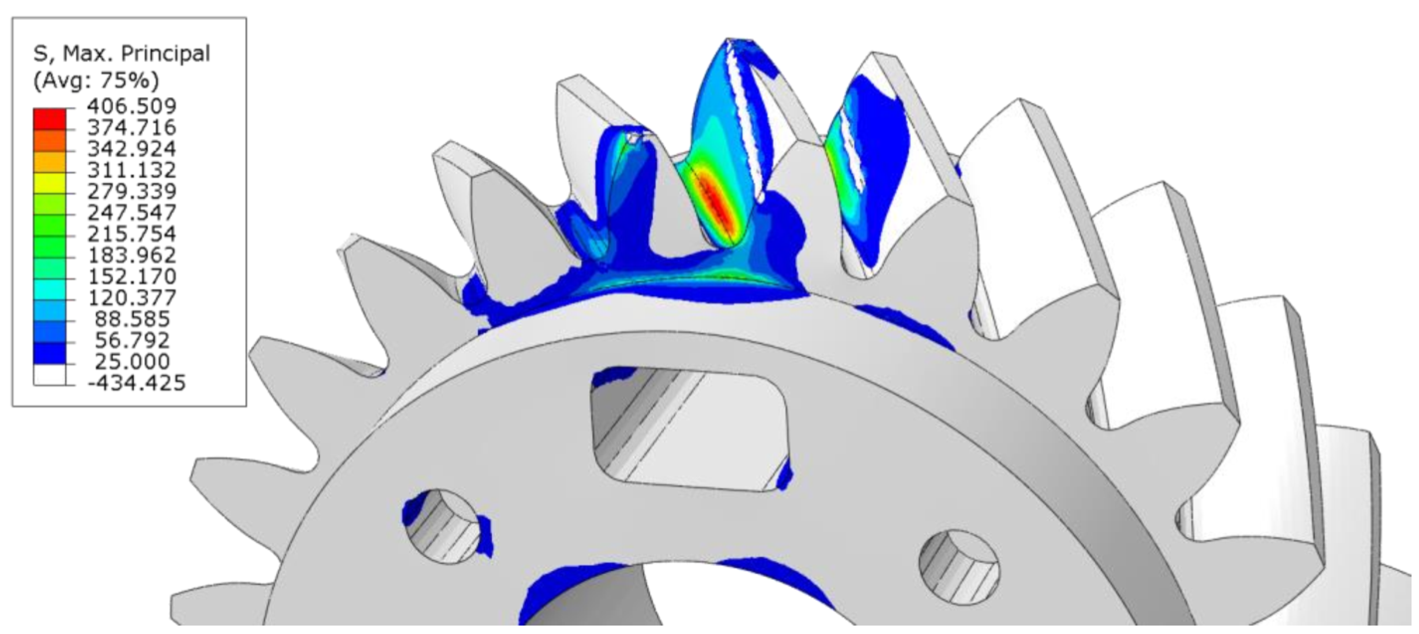
5. Evaluation of the Sensor Port Effect on the Tooth Root Stress

A first attempt to estimate the effect that sensor integration will have on the tooth load carrying capacity can be carried out following the classical gear standards, such as ISO 6336-1 [50] and ISO 6336-3 [52]. On the one hand, by means of the gear blank factor C R , which modifies the gear stiffness, ISO 6336-1 [50] allows designers to include the effect of the gear body shape within the classical gear assessment methods. On the other hand, the effect of the rim thickness on the tooth root stress is also included in ISO 6336-3 [52] by means of the rim thickness factor Y B . It is worth mentioning that according to ISO 6336-2 [51], the rim thickness has no direct effect on the contact stress.
However, [50,52] consider a simple gear geometry, in which the whole gear body presents a thin rim. That is, while it seems reasonable to evaluate the possibility of a purely standards-based assessment for a gear body with a shape similar to those shown in Figure 3, the same cannot be applied to the proposed geometry because the result outcome is quite different to the standard. Hence, the necessity of adopting a generalized evaluation method. Following the suggestion of [61,62,63,64,65,66], numerical models have been implemented.
Here, static meshing gear simulation has been evaluated by following the procedure described in previous papers [77,78], where the simulation is carried out in separate rotational steps. Two separate reference points, located at the center of each gear, are connected to the gear hub by a multi-point constraint. Tooth flank contact is defined by surface-to-surface contact. The pinion is fixed while the wheel is free to rotate. When torque is applied on the wheel, it rotates by a small quantity in order to establish the loaded contact between teeth flanks, and the load is then transmitted from one gear to the other. Figure 7 summarizes the FE procedure. All the FE simulations discussed here have been performed using ABAQUS 2020.
Several rotational steps are then simulated thanks to an external phyton code which rotates each gear on its axis by a rotational step that depends on the wheel/pinion number of teeth and the number of the simulation step. The comparison was been made by looking at the meshing position that results in a higher tooth root stress. Following the indication of Conrado, E. and Davoli, P. [65], the maximum principal component of the stress tensor is adopted as a reference stress.
Here, it is worth mentioning that the FE tooth root stress result and the result estimated according to the ISO 6336 series framework [50,51,52,53] cannot be directly compared. Indeed, even though they are both estimating a stress in the tooth root region, the estimated stress values are calculated with different assumptions and methodologies, and cannot be directly compared. The stress number predicted by ISO 6336-3 [52] is the maximum local principal stress, calculated by considering only the tangential force and evaluated at 30° tangents to the contact of the root fillets, while the stress predicted by FEM is a stress tensor, defined all over the model, which considers all the forces exchanged by the teeth.
In order to reduce the computational time, the calculation procedure was based on two models. The first, based on tetrahedral elements, estimated the load sharing between teeth. Then, a second model based on hexahedral elements exploited the sub-modeling technique in order to estimate the actual tooth root stress.
Both the original geometry, the modified geometry (i.e., with the port), as well as the geometry with the hole for the thermocouple were simulated. However, due to the complex geometry, it was not possible to proceed with the sub-modelling for the case with the hole for the thermocouple. Figure 8 and Figure 9 show an example of results for the main model with port and its sub-model, respectively. Figure 10 highlights the contact area estimated for the case in Figure 9. The calculated contact area was in agreement with the general assumption that the contact line ending at the top edge of a helical gear is relevant for maximum tooth root stress levels [79]. The calculated equivalent stresses are summarized in Table 3.
Nevertheless, in order to properly estimate the effect of sensor integration within the tooth root, it is necessary to consider that the interference fit is loading the root region, as shown in Figure 5. However, while the meshing stress can be schematized as a pulsating stress, the same cannot be done for the interference fit because it is a constant stress. Therefore, a simple arithmetic summation of the stress is not correct from the point of fatigue, but considering the multiaxial nature of the stress, high-cycle multiaxial fatigue criteria were adopted. Among the numerous criteria available in the literature (e.g., [80]), considering the simple load case, the Sines criteria was adopted.
Hence, the stress tensors estimated by both the two FE models were extracted and combined. The equivalent stress was compared for the cases as a means to estimate the effect of the gear body modification. The result of such comparison was the ratio between the various representative stress levels. Both cases with and without the interference fit were evaluated. Table 4 summarizes the results. As can be seen, the effect of the interference fit was predominant. Therefore, its neglection would have led to an underestimation of the sensor port effect. In any case, if the ratios Table 4 were considered as factors multiplying the tooth root stress, thanks to proper gear design, S F always remains higher than 1.5.

6. Results and Conclusions

Within the context of the development of smart mechanical elements, the effect of sensor integration within a gear has been discussed. The focus of this article was an actual case-hardened helical gear pair to be used within an actual gearbox. This article shows that sensor integration in an industrial-grade gear is a feasible idea, however, the designer should expect a reduction in the gear load carrying capacity.
After introducing the proposed gear body modifications and their rationale, a procedure for estimating the related load carrying capacity reductions was presented. Due to the limitations of the classical analytical approach, a FE procedure was adopted. The performed simulations aimed to evaluate the influence that the addition of the sensor ports had on the load carrying capacity of the gear.
Interference fit simulations were performed in order to estimate the effect of the sensor port on the tapered interference fit. Meshing gear simulations were also conducted as a means to evaluate the impact of the sensor port on tooth root stress.
The effect of the geometry modification was estimated by comparing the results of both the modified and the unmodified gear pair, adopting the model with the same parameters (e.g., element type and dimensions). Furthermore, in order to consider the interaction of gear meshing and interference fit, the Sines criteria was adopted as a means to determine the effect of the sensor integration on the tooth root from the point of view of fatigue. The geometry proposed here is indeed the product of all the aforementioned considerations. During its development, thanks to robust gear design (i.e., see Table 1 safety factor), the real bottle neck was found to be in the interference fit rather than in the tooth root bending strength.
As a general result, it holds that the proper design of a sensor-integrated gear needs to trade part of its load carrying capacity for the additional intelligence in the form of space for sensors.
Only static behavior has been considered. Since gear stiffness is modified by the sensor integration and load sharing between the teeth, the Noise Vibration Harshness (NVH) behavior will also subsequently change. This aspect will be a part of future numerical and experimental analysis.

Author Contributions

Conceptualization, L.B. and E.K.; methodology, L.B., E.K. and M.O.; software, L.B.; supervision, M.O., C.G. and K.S.; Writing, L.B. and E.K. All authors have read and agreed to the published version of the manuscript.

Funding

This research was funded by founded by the German Research Foundation (DFG, Deutsche Forschungsgemeinschaft) through the SIZA (Sensor integrated gear, Sensor-Integrierendes Zahnrad) project (grant number 466653706).

Data Availability Statement

Not applicable.

Acknowledgments

The authors would like to express their gratitude to Ermal Fierza and Ralf Brederlow for the development of the electronic boards as well their collaboration in the integration process of the electrical components within the SIZA project.

Conflicts of Interest

The authors declare no conflict of interest.

References

  1. De Solla Price, D. Gears from the Greeks. The Antikythera Mechanism: A Calendar Computer from ca. 80 B. C. Trans. Am. Philos. Soc. 1974, 64, 1. [Google Scholar] [CrossRef]
  2. Litvin, F.L. Development of Gear Technology and Theory of Gearing; National Aeronautics and Space Administration, Lewis Research Center: Cleveland, OH, USA, 1997; Volume 1406.
  3. Reti, L. Leonardo on Bearings and Gears. Sci. Am. 1971, 224, 100–111. [Google Scholar] [CrossRef]
  4. Ziegler, L.; Gonzalez, E.; Rubert, T.; Smolka, U.; Melero, J.J. Lifetime Extension of Onshore Wind Turbines: A Review Covering Germany, Spain, Denmark, and the UK. Renew. Sustain. Energy Rev. 2018, 82, 1261–1271. [Google Scholar] [CrossRef] [Green Version]
  5. Farrar, C.R.; Worden, K. An Introduction to Structural Health Monitoring. Philos. Trans. R. Soc. A Math. Phys. Eng. Sci. 2006, 365, 303–315. [Google Scholar] [CrossRef] [PubMed]
  6. Sait, A.S.; Sharaf-Eldeen, Y.I. A Review of Gearbox Condition Monitoring Based on Vibration Analysis Techniques Diagnostics and Prognostics. In Rotating Machinery, Structural Health Monitoring, Shock and Vibration, Volume 5; Conference Proceedings of the Society for Experimental Mechanics Series; Springer: New York, NY, USA, 2011; Volume 5, pp. 307–324. [Google Scholar] [CrossRef]
  7. Wang, T.; Han, Q.; Chu, F.; Feng, Z. Vibration Based Condition Monitoring and Fault Diagnosis of Wind Turbine Planetary Gearbox: A Review. Mech. Syst. Signal Process. 2019, 126, 662–685. [Google Scholar] [CrossRef]
  8. Nie, M.; Wang, L. Review of Condition Monitoring and Fault Diagnosis Technologies for Wind Turbine Gearbox. Procedia CIRP 2013, 11, 287–290. [Google Scholar] [CrossRef] [Green Version]
  9. Salameh, J.P.; Cauet, S.; Etien, E.; Sakout, A.; Rambault, L. Gearbox Condition Monitoring in Wind Turbines: A Review. Mech. Syst. Signal Process. 2018, 111, 251–264. [Google Scholar] [CrossRef]
  10. Sendlbeck, S.; Fimpel, A.; Siewerin, B.; Otto, M.; Stahl, K. Condition Monitoring of Slow-Speed Gear Wear Using a Transmission Error-Based Approach with Automated Feature Selection. Int. J. Progn. Health Manag. 2021, 12. [Google Scholar] [CrossRef]
  11. Concli, F.; Pierri, L.; Sbarufatti, C. A Model-Based SHM Strategy for Gears—Development of a Hybrid FEM-Analytical Approach to Investigate the Effects of Surface Fatigue on the Vibrational Spectra of a Back-to-Back Test Rig. Appl. Sci. 2021, 11, 2026. [Google Scholar] [CrossRef]
  12. Fromberger, M.L.; Kohn, B.; Utakapan, T.; Otto, M.; Stahl, K. Condition Monitoring by Position Encoders. In Proceedings of the INTER-NOISE and NOISE-CON Congress and Conference Proceedings, Hamburg, Germanny, 21–24 August 2016; Institute of Noise Control Engineering: Reston, VA, USA, 2016; Volume 253, pp. 7451–7459. [Google Scholar]
  13. Feng, K.; Borghesani, P.; Smith, W.A.; Randall, R.B.; Chin, Z.Y.; Ren, J.; Peng, Z. Vibration-Based Updating of Wear Prediction for Spur Gears. Wear 2019, 426–427, 1410–1415. [Google Scholar] [CrossRef]
  14. Sendlbeck, S.; Otto, M.; Stahl, K. A Gear Damage Estimation and Propagation Approach by Combining Simulated and Measured Transmission Error Data. In Proceedings of the International Conference on Advanced Vehicle Powertrains 2021, Beijing, China, 2–4 September 2021. [Google Scholar]
  15. Fromberger, M.; Sendlbeck, S.; Rothemund, M.; Götz, J.; Otto, M.; Stahl, K. Comparing Data Sources for Condition Monitoring Suitability. Forsch. Ingenieurwes. 2019, 83, 521–527. [Google Scholar] [CrossRef]
  16. Sendlbeck, S.; Fromberger, M.; Otto, M.; Stahl, K. Vibration-Based Gear Condition Monitoring Using an Improved Section-Specific Approach without the Need of Historic Reference Data. In Proceedings of the 27th International Congress on Sound and Vibration (ICSV2021), Online, 11–16 July 2021. [Google Scholar]
  17. Fromberger, M.; Weinberger, U.; Kohn, B. Evaluating Signal Processing Methods for Use in Gearbox Condition Monitoring. In Proceedings of the 24th international congress on sound and vibration, London, UK, 23–27 July 2017. [Google Scholar]
  18. Sensorintegrierende Maschinenelemente—Wegbereiter Der Flächendeckenden Digitalisierung. Available online: https://www.spp2305.de/ (accessed on 7 August 2022).
  19. Holm-Hansen, B.T.; Gao, R.X. Time-Scale Analysis Adapted for Bearing Diagnostics. In Proceedings of the SPIE 3833, Intelligent Systems in Design and Manufacturing II, Boston, MA, USA, 20 August 1999; Volume 3833. [Google Scholar]
  20. Holm-Hansen, B.T.; Gao, R.X. Monitoring of Loading Status Inside Rolling Element Bearings Through Electromechanical Sensor Integration. In Proceedings of the ASME International Mechanical Engineering Congress and Exposition, Proceedings (IMECE), Dallas, TX, USA, 16–21 November 1997; pp. 329–335. [Google Scholar] [CrossRef]
  21. Holm-Hansen, B.T.; Gao, R.X. Multiple Defect Analysis of a Sensor Integrated Ball Bearing. In Proceedings of the ASME International Mechanical Engineering Congress and Exposition, Proceedings (IMECE), Anaheim, CA, USA, 15–20 November 1998; pp. 9–14. [Google Scholar] [CrossRef]
  22. Holm-Hansen, B.T.; Gao, R.X. Smart Bearing Utilizing Embedded Sensors: Design Considerations. In Proceedings of the Smart Structures and Materials 1997: Smart Structures and Integrated Systems, San Diego, CA, USA, 3–6 March 1997; Volume 3041, pp. 602–610. [Google Scholar] [CrossRef]
  23. Holm-Hansen, B.T.; Gao, R.X. Integrated Microsensor Module for a Smart Bearing with On-Line Fault Detection Capabilities. In Proceedings of the Conference Record—IEEE Instrumentation and Measurement Technology Conference, Ottawa, ON, Canada, 19–21 May 1997; Volume 2, pp. 1160–1163. [Google Scholar] [CrossRef]
  24. Holm-Hansen, B.T.; Gao, R.X. Vibration Analysis of a Sensor-Integrated Ball Bearing. J. Vib. Acoust. 2000, 122, 384–392. [Google Scholar] [CrossRef]
  25. Holm-Hansen, B.T.; Gao, R.X. Structural Design and Analysis for a Sensor-Integrated Ball Bearing. Finite Elem. Anal. Des. 2000, 34, 257–270. [Google Scholar] [CrossRef]
  26. Gao, R.X.; Holm-Hansen, B.T.; Wang, C. Design of a Mechatronic Bearing through Sensor Integration. In Proceedings of the SPIE 3518, Sensors and Controls for Intelligent Machining, Agile Manufacturing, and Mechatronics, Boston, MA USA, 17 December 1998; Volume 3518. [Google Scholar]
  27. Holm-Hansen, B.T.; Gao, R.X.; Zhang, L. Customized Wavelet for Bearing Defect Detection. J. Dyn. Syst. Meas. Control 2004, 126, 740–745. [Google Scholar] [CrossRef]
  28. Schirra, T.; Martin, G.; Vogel, S.; Kirchner, E. Ball Bearings as Sensors for Systematical Combination of Load and Failure Monitoring. In Proceedings of the International Design Conference, Dubrovnik, Croatia, 21–24 May 2018; Volume 6, pp. 3011–3022. [Google Scholar] [CrossRef]
  29. Schirra, T.; Martin, G.; Kirchner, E. Design of and with Sensing Macine Elements—Using the Example of a Sensing Rolling Bearing. Proc. Des. Soc. 2021, 1, 1063–1072. [Google Scholar] [CrossRef]
  30. Vogel, S.; Martin, G.; Schirra, T.; Kirchner, E. Robust Design for Mechatronic Machine Elements—How Robust Design Enables the Application of Mechatronic Shaft-Hub Connection. In Proceedings of the International Design Conference, Dubrovnik, Croatia, 21–24 May 2018; Volume 6, pp. 3033–3040. [Google Scholar] [CrossRef]
  31. Groche, P.; Brenneis, M. Manufacturing and Use of Novel Sensoric Fasteners for Monitoring Forming Processes. Measurement 2014, 53, 136–144. [Google Scholar] [CrossRef]
  32. Gräbner, D.; Dödtmann, S.; Dumstorff, G.; Lucklum, F. 3-D-Printed Smart Screw: Functionalization during Additive Fabrication. J. Sens. Sens. Syst. 2018, 7, 143–151. [Google Scholar] [CrossRef]
  33. Möhring, H.C.; Bertram, O. Integrated Autonomous Monitoring of Ball Screw Drives. CIRP Ann. 2012, 61, 355–358. [Google Scholar] [CrossRef]
  34. Biehl, S.; Staufenbiel, S.; Recknagel, S.; Denkena, B.; Bertram, O. Thin film sensors for condition monitoring in ball screw drives. In Proceedings of the 1st Joint International Symposium on System-Integrated Intelligence, Hannover, Germany, 28–29 June 2012; pp. 27–29. [Google Scholar]
  35. Biehl, S.; Staufenbiel, S.; Hauschild, F.; Albert, A. Novel Measurement and Monitoring System for Forming Processes Based on Piezoresistive Thin Film Systems. Microsyst. Technol. 2010, 16, 879–883. [Google Scholar] [CrossRef]
  36. Peters, J.; Ott, L.; Gwosch, T.; Matthiesen, S. Requirements for Sensor Integrating Machine Elements: A Review of Wear and Vibration Characteristics of Gears. Sens. Integr. Gears 2020. [Google Scholar] [CrossRef]
  37. Peters, J.; Ott, L.; Dörr, M.; Gwosch, T.; Matthiesen, S. Design of Sensor Integrating Gears: Methodical Development, Integration and Verification of an in-Situ MEMS Sensor System. Procedia CIRP 2021, 100, 672–677. [Google Scholar] [CrossRef]
  38. Peters, J.; Ott, L.; Dörr, M.; Gwosch, T.; Matthiesen, S. Sensor-Integrating Gears: Wear Detection by in-Situ MEMS Acceleration Sensors. Forsch. Ingenieurwes. 2022, 86, 421–432. [Google Scholar] [CrossRef]
  39. Sridhar, V.; Chana, K. Development of a Novel Sensor for Gear Teeth Wear and Damage Detection. Int. J. Progn. Health Manag. 2021, 12. [Google Scholar] [CrossRef]
  40. Binder, M.; Stapff, V.; Heinig, A.; Schmitt, M.; Seidel, C.; Reinhart, G. Additive Manufacturing of a Passive, Sensor-Monitored 16MnCr5 Steel Gear Incorporating a Wireless Signal Transmission System. Procedia CIRP 2022, 107, 505–510. [Google Scholar] [CrossRef]
  41. Schmitt, M.; Kamps, T.; Siglmüller, F.; Winkler, J.; Schlick, G.; Seidel, C.; Tobie, T.; Stahl, K.; Reinhart, G. Laser-Based Powder Bed Fusion of 16MnCr5 and Resulting Material Properties. Addit. Manuf. 2020, 35, 101372. [Google Scholar] [CrossRef]
  42. Bonaiti, L.; Concli, F.; Gorla, C.; Rosa, F. Bending Fatigue Behaviour of 17-4 PH Gears Produced via Selective Laser Melting. Procedia Struct. Integr. 2019, 24, 764–774. [Google Scholar] [CrossRef]
  43. Concli, F.; Bonaiti, L.; Gerosa, R.; Cortese, L.; Nalli, F.; Rosa, F.; Gorla, C. Bending Fatigue Behavior of 17-4 PH Gears Produced by Additive Manufacturing. Appl. Sci. 2021, 11, 3019. [Google Scholar] [CrossRef]
  44. Kadach, D. FVA-Heft Nr. 1205 Einfluss Der Lastverteilung Auf Die Grübchentragfähigkeit von Einsatzgehärteten Stirnrädern; Forschungsvereinigung Antriebstechnik e.V. (FVA): Frankfurt, Germany, 2017. [Google Scholar]
  45. Kadach, D. FVA-Heft Nr. 1164—Einfluss von Stillstandsmarkierungen Auf Die Flankentragfähigkeit von Zahnrädern; Forschungsvereinigung Antriebstechnik e.V. (FVA): Frankfurt, Germany, 2015. [Google Scholar]
  46. Kadach, D.; Tobie, T.; Stahl, K. Fretting Lines on Gears—Systematic Investigations on the Formation Conditions and Mechanisms. In Proceedings of the JSME international conference on motion and power transmissions, Kyoto, Japan, 28 February–3 March 2017; Volume 2017, pp. 4–5. [Google Scholar] [CrossRef]
  47. Kadach, D.; Matt, P.; Tobie, T.; Stahl, K. Influences of the Facing Edge Condition on the Flank Load Carrying Capacity of Helical Gears. In Proceedings of the ASME 2015 International Design Engineering Technical Conferences and Computers and Information in Engineering Conference, Boston, MA, USA, 2–5 August 2015. [Google Scholar] [CrossRef]
  48. Kadach, D. Stillstandsmarkierungen an Zahnrädern Und Deren Auswirkungen Auf Die Flankentragfähigkeit. Ph.D. Thesis, Technische Universität München, München, Germany, 2015. [Google Scholar]
  49. ISO 14635-1; Gears—FZG Test Procedures—Part 1: FZG Test Method A/8,3/90 for Relative Scuffing Load-Carrying Capacity of Oils. International Organization for Standardization: Geneva, Switzerland, 2006.
  50. Hoehn, B.-R.; Oster, P.; Tobie, T. Test Methods for Gear Lubricants. Michaelis Metode Ispitivanja. Goriva Maz. 2008, 47, 129–152. [Google Scholar]
  51. ISO 6336-1: 2006; Calculation of Load Capacity of Spur and Helical Gears—Part 1: Basic Principles, Introduction and General Influence Factors. International Organization for Standardization: Geneva, Switzerland, 2006.
  52. ISO 6336-2:2019; Calculation of Load Capacity of Spur and Helical Gears—Part 2: Calculation of Surface Durability (Pitting). International Organization for Standardization: Geneva, Switzerland, 2019.
  53. ISO 6336-3:2019; Calculation of Load Capacity of Spur and Helical Gears—Part 3: Calculation of Tooth Bending Strength. International Organization for Standardization: Geneva, Switzerland, 2019.
  54. ISO 6336-5:2019; Calculation of Load Capacity of Spur and Helical Gears—Part 5: Strength and Quality of Materials. International Organization for Standardization: Geneva, Switzerland, 2019.
  55. ISO 6336-6:2019; Calculation of Load Capacity of Spur and Helical Gears—Part 6: Calculation of Service Life under Variable Load. International Organization for Standardization: Geneva, Switzerland, 2019.
  56. Götz, J.; Sepp, S.; Otto, M.; Stahl, K. Low Excitation Spur Gears with Variable Tip Diameter. In INTER-NOISE and NOISE-CON Congress and Conference Proceedings; Institute of Noise Control Engineering: Washington, DC, USA, 2021; Volume 263, pp. 1275–1285. [Google Scholar]
  57. Utakapan, T.; Kohn, B.; Fromberger, M.; Otto, M.; Stahl, K. Evaluation of Gear Noise Behaviour with Application Force Level: Conference Proceedings. Forsch. Ingenieurwes. 2017, 81, 59–64. [Google Scholar] [CrossRef]
  58. Enthoven, J.C.; Cann, P.M.; Spikes, H.A. Temperature and Scuffing. Tribol. Trans. 1993, 36, 258–266. [Google Scholar] [CrossRef]
  59. Bowman, W.F.; Stachowiak, G.W. A Review of Scuffing Models. Tribol. Lett. 1996, 2, 113–131. [Google Scholar] [CrossRef]
  60. Niemann, G.; Winter, H.; Höhn, B.-R.; Stahl, K. Maschinenelemente 1. In Maschinenelemente 1; Springer: Berlin, Germany, 2019. [Google Scholar] [CrossRef]
  61. Bibel, G.D.; Reddy, S.K.; Savage, M.; Handschuh, R.F. Effects of Rim Thickness on Spur Gear Bending Stress. J. Mech. Des. 1994, 116, 1157–1162. [Google Scholar] [CrossRef]
  62. Marunić, G. Effects of Rim and Web Thickness on Gear Tooth Root, Rim and Web Stresses. Key Eng. Mater. 2008, 385–387, 117–120. [Google Scholar] [CrossRef]
  63. Oda, S.; Nagamura, K.; Aoki, K. Stress Analysis of Thin Rim Spur Gears by Finite Element Method. Bull. JSME 1981, 24, 1273–1280. [Google Scholar] [CrossRef]
  64. Li, S. Deformation and Bending Stress Analysis of a Three-Dimensional, Thin-Rimmed Gear. J. Mech. Des. 2002, 124, 129–135. [Google Scholar] [CrossRef]
  65. Conrado, E.; Davoli, P. The “True” Bending Stress in Spur Gears. Gear Technol. 2007, 8, 52–57. [Google Scholar]
  66. Kawalec, A.; Wiktor, J. Tooth-Root Stress Calculation of Internal Spur Gears. Proc. Inst. Mech. Eng. B J. Eng. Manuf. 2004, 218, 1153–1166. [Google Scholar] [CrossRef]
  67. Politis, D.J.; Politis, N.J.; Lin, J. Review of Recent Developments in Manufacturing Lightweight Multi-Metal Gears. Prod. Eng. 2021, 15, 235–262. [Google Scholar] [CrossRef]
  68. Ramadani, R.; Pal, S.; Kegl, M.; Predan, J.; Drstvenšek, I.; Pehan, S.; Belšak, A. Topology Optimization and Additive Manufacturing in Producing Lightweight and Low Vibration Gear Body. Int. J. Adv. Manuf. Technol. 2021, 113, 3389–3399. [Google Scholar] [CrossRef]
  69. Mura, A.; Curà, F.; Pasculli, L. Optimisation Methodology for Lightweight Gears to Be Produced by Additive Manufacturing Techniques. Proc. Inst. Mech. Eng. C J. Mech. Eng. Sci. 2017, 232, 3512–3523. [Google Scholar] [CrossRef]
  70. Truman, C.E.; Booker, J.D. Analysis of a Shrink-Fit Failure on a Gear Hub/Shaft Assembly. Eng. Fail. Anal. 2007, 14, 557–572. [Google Scholar] [CrossRef]
  71. Strozzi, A.; Baldini, A.; Giacopini, M.; Bertocchi, E.; Bertocchi, L. Achievement of a Uniform Contact Pressure in a Shaft–Hub Press-Fit. Proc. Inst. Mech. Eng. Part C J. Mech. Eng. Sci. 2012, 227, 405–419. [Google Scholar] [CrossRef]
  72. Leonhardt, C.; Otto, M.; Stahl, K. Potential of Lightweight Construction and Component Properties of Joined Spur Gears. In Dritev-Getriebe in Fahrzeugen; VDI Wissensforum GmbH: Dusseldorf, Germany, 2019. [Google Scholar]
  73. Chu, S.J.; Jeong, T.K.; Jung, E.H. Effect of Radial Interference on Torque Capacity of Press- and Shrink-Fit Gears. Int. J. Automot. Technol. 2016, 17, 763–768. [Google Scholar] [CrossRef]
  74. Bae, J.H.; Kim, J.S.; Hwang, B.C.; Bae, W.B.; Kim, M.S.; Kim, C. Prediction of the Dimensional Deformation of the Addendum and Dedendum after the Warm Shrink Fitting Process Using a Correction Coefficient. Int. J. Automot. Technol. 2012, 13, 285–291. [Google Scholar] [CrossRef]
  75. Leonhardt, C. FVA 797—Einfluss von Querpressverbänden Auf Die Zahnfußtragfähigkeit Außenverzahnter Stirnradverzahnungen; Forschungsvereinigung Antriebstechnik e.V. (FVA): Frankfurt, Germany, 2021. [Google Scholar]
  76. Güven, F. Effect of Design Parameters on Stresses Occurring at the Tooth Root in a Spur Gear Pressed on a Shaft. Proc. Inst. Mech. Eng. Part E J. Process Mech. Eng. 2021, 235, 1164–1174. [Google Scholar] [CrossRef]
  77. Gorla, C.; Rosa, F.; Conrado, E.; Tesfahunegn, Y.A. Combined Effects of Lead Crowning and Assembly Deviations on Meshing Characteristics of Helical Gears. Int. J. Appl. Eng. Res. 2016, 11, 11681–11694. [Google Scholar]
  78. Bonaiti, L.; Bayoumi, A.B.M.; Concli, F.; Rosa, F.; Gorla, C. Gear Root Bending Strength: A Comparison between Single Tooth Bending Fatigue Tests and Meshing Gears. J. Mech. Des. Trans. ASME 2021, 143, 103402. [Google Scholar] [CrossRef]
  79. Broßmann, U. Über Den Einfluß Der Zahnfußausrundung Und Des Schrägungswinkels Auf Beanspruchung Und Festigkeit Schrägverzahnter Stirnräder. Ph.D. Thesis, Technische Universität München, München, Germany, 1979. [Google Scholar]
  80. Papadopoulos, I.V.; Davoli, P.; Gorla, C.; Filippini, M.; Bernasconi, A. A Comparative Study of Multiaxial High-Cycle Fatigue Criteria for Metals. Int. J. Fatigue 1997, 19, 219–235. [Google Scholar] [CrossRef]
Figure 1. The proposed final gear body geometry (left) that has been defined by modifying the original one (right).
Machines 10 00888 g001
Figure 2. Reference scheme of the 91.5 power-recirculating test rig [50].
Machines 10 00888 g002
Figure 3. Examples of not-feasible gear body geometries. (a,b) are two possible geometries with a different position and size of the sensor board.
Machines 10 00888 g003
Figure 4. FE simulation procedure for the evaluation of the port effect of the interference fit.
Machines 10 00888 g004
Figure 5. FE results of the interference fit.
Machines 10 00888 g005
Figure 6. FE results of the interference fit, with a focus on the stress inside the sensor port.
Machines 10 00888 g006
Figure 7. FE simulation procedure for the estimation of tooth root bending stress. The “Machines 10 00888 i001” symbol rep-resent an encastre while the “Machines 10 00888 i002” one represent a locating-type constraint.
Machines 10 00888 g007
Figure 8. Example of main model FE results showing the maximum principal stress (Modified Geometry).
Machines 10 00888 g008
Figure 9. Example of sub-model FE results showing the maximum principal stress (Modified Geometry).
Machines 10 00888 g009
Figure 10. Example of sub-model FE results showing the contact pressure (Modified Geometry).
Machines 10 00888 g010
Table 1. Main geometrical data and calculated safety factors acc. to ISO 6336 [51,52,53,54,55].
NameSymbolPinionWheelU.M.
Number of teethz2224-
Normal modulus m n 4.25Mm
Normal pressure angle α n 20°
Helix angle β 29°
Profile shift coefficient X 0.1000.077-
Centre distance a 112.5Mm
Tip diameter d a 117.70127.30Mm
Addendum factor of the basic rack h a p 1.55-
Tooth root radius factor ρ f P 0.25-
Facewidth b 27.6Mm
Torque T 1000Nm
Rotational velocity n 3000Rpm
Working hours H 2000H
Contact stress σ H 15281527MPa
Pitting stress limit σ H G 1536MPa
Safety factor, pitting S H 1.011.01-
Nominal tooth root stress σ F 432433MPa
Allowable stress number for bending σ F E 950MPa
Safety factor, tooth root bending fatigue S F 2.102.09-
Table 2. Input data and calculated safety factors for the interference fit.
d l T τ θ τ z p m i n p a v g , F E M S I F
mmmmNmMPaMPaMPaMPa-
Baseline505510004.631.37248.32204.56
Modified1863.85
Table 3. Maximum tooth root stress estimated by the FE models.
σ I
[MPa]
σ V M
[MPa]
Original GeometryMain model396337
Sub model336290
Modified GeometryMain model407353
Sub model349302
Modified Geometry with thermocouple holeMain model440380
Table 4. Estimated effect of the sensor integration in the tooth root bending stress.
Without Interference FitWith Interference Fit
Modified GeometryMain model1.051.12
Sub model1.041.12
Modified Geometry with thermocouple holeMain model1.131.22
Publisher’s Note: MDPI stays neutral with regard to jurisdictional claims in published maps and institutional affiliations.

