Article

Study on the Nonlinear Dynamic Behavior of Rattling Vibration in Gear Systems

1
School of Mechatronics Engineering, Harbin Institute of Technology, 92 Xidazhi Street, Nangang District, Harbin 150001, China
2
School of Mechanical and Power Engineering, Harbin University of Science and Technology, 52 Xuefu Rd., Nangang District, Harbin 150080, China
3
Institute of Foreign Languages, Wuhan University of Science and Technology, 2 Huangjiahu West Rd., Hongshan District, Wuhan 430065, China
*
Author to whom correspondence should be addressed.
Machines 2022, 10(12), 1112; https://doi.org/10.3390/machines10121112
Submission received: 21 October 2022 / Revised: 9 November 2022 / Accepted: 14 November 2022 / Published: 23 November 2022
(This article belongs to the Section Machine Design and Theory)

Abstract

:
To reveal the nonlinear dynamic behavior of gear rattling vibration caused by gear backlash, a 2-DOF oscillator model with spring and damping elements was established. Based on the theory of discontinuous dynamical systems, the phase plane of gear motion was divided into three parts: the domain of tooth surface meshing motion, the domain of free motion and the domain of tooth back meshing motion. Introducing the global mapping and local mapping dynamics method, the process of gear teeth from impact to meshing and then impact and meshing was accurately described. The influence of different restitution coefficients on gear impact-meshing motion was studied by numerical simulation. The results showed that the grazing bifurcation caused by gear backlash will lead to complex mapping structures of the system and even chaos. The restitution coefficient directly affects the impact-meshing behavior. The introduction of meshing stiffness and restitution coefficient can reasonably characterize the elastic deformation and energy loss during gear meshing, which provides a theoretical model for the application of the theory of discontinuous dynamical systems to a more complex multi-degree of freedom flexible contact gear transmission system.

1. Introduction

The gear transmission system plays a key role in key parts of aviation, aerospace, automobile, ship, mining, metallurgy, robot and other fields [1]. The safe, stable and reliable operation of this equipment is related to economic benefits and all aspects of social life.
Gear transmission system dynamics is an engineering science to study the dynamic behavior of gear transmission systems under dynamic excitation [2]. In the process of gear transmission, due to the needs of manufacturing, installation and lubrication, backlash is inevitable. The existence of gear backlash makes the vibration phenomenon more complex and produces great noise and dynamic load, especially noise caused by light load [3].
In the aero-engine accessory transmission system, the sudden change of driving force caused by the maneuvering behavior of the aircraft will lead to high-frequency impact and meshing between gear teeth, which is intuitively shown as gear rattling vibration noise. In a high-precision gearbox, the nonlinear rattling vibration of the system will also cause defects of and damage to the gear [4]. It is of great significance to study the scientific laws of impact, vibration and noise generated by gear transmission system in the process of transmitting motion and power to provide theoretical guidance for designing and manufacturing gear transmission systems with low noise, weak vibration, high efficiency and high reliability.

1.1. Research on Rattling Vibration of Gear Pairs

Rattling vibration is a strong nonlinear problem. In recent years, many scholars have studied the nonlinear dynamic behavior of gear rattling vibration. He [5] established a dynamic model of a single pair gear transmission and solved it by Runge Kutta method, analysed the dynamic response of the model, and summarized the methods to reduce the rattling vibration of the system. Liu [6] studied the nonlinear dynamic model of a non-circular gear system that considers gear backlash, static transmission error and multifrequency parametric excitation, and found that with the increase in the amplitude of error, eccentricity ratio and rotational speed, the system will experience nonrattling, unilateral rattling and bilateral rattling states. Rigaud [7] conducted an experimental study on rattling vibration between gear teeth, analysed the influence of drag torque, driving excitation amplitude and frequency on the system, and analysed the dynamic behavior of gear rattling vibration. It was found that the ratio of excitation frequency to rotation frequency would have a direct impact on rattling vibration between gear teeth. Guo [8] established a single pair gear transmission model considering time-varying backlash, time-varying stiffness and nonlinear oil film force, and analysed the influence of torque fluctuation and damping viscosity on the dynamic behavior of gear rattling vibration. Liang [9] established an equivalent dynamic model of the gear rattling system, solved the nonlinear dynamic response of the system by using the integral method, and studied the influence of key factors on the nonlinear dynamic performance of the system by using the bifurcation diagram, spectrum diagram and Poincaré map.
Zhang [10] established a non-linear dynamic model to investigate the gear rattle issue appearing in novel power-split hybrid transmission, and found that the system resonances are not directly related to the hybrid transmission rattle. Dong [11] established a lumped mass gear-rattling model with backlash considering the time-varying mesh stiffness, composite transmission error and torque fluctuation. The concepts of “high speed impact” and “low speed contact” in gear-rattling are proposed. Yoon [12] investigated the gear rattle phenomena on unloaded gear pairs with different excitation conditions and various system parameters. The effects of various system parameters on the vibro-impacts are examined using a nonlinear system model.

1.2. Research on the Theory of Discontinuous Dynamical Systems

In the past, the method of continuous dynamic system was usually used in the study of systems with backlash, while the theory of discontinuous dynamical systems was not well applied.
In 1995, Han, Luo and Deng [13] jointly proposed the theory of discontinuous dynamical systems, and analysed the motion of a two-degree-of-freedom oscillator model. Based on the mapping dynamics, four transformation maps were given, and the periodicity and bifurcation behavior of the motion in the steady state were analysed. Luo [14] determined the global mapping structures of a single-degree-of-freedom vibration system based on mapping dynamics, studied the bifurcation under the change in external excitation frequency through numerical simulation, and analysed the stability of motion.
Luo [15] further proposed the theory of discontinuous dynamical systems in the time-varying domain in 2005. The key of the theory is that, inspired by the physical energy layer, the core concept of “G function” is proposed for the time-varying boundary of discontinuous dynamical systems. In essence, the G function is to give a local measurement method at any point of the time-varying boundary with the method of limit, which makes it possible to study the switch of flow on the time-varying boundary in detail [16]. In 2009, Luo [17] used a two-degree-of-freedom oscillator model to simulate the impact and meshing behavior between gears to reveal the impact-meshing mechanism of gear pairs. The existence of periodic motion was numerically analysed by using meshing and grazing conditions, and periodic motion was analysed and predicted with mapping structures, and corresponding local stability and bifurcation analysis were carried out. However, due to its rigid contact model, it cannot reflect the actual working state of the gear and cannot be directly applied to the actual working condition of the gear pair transmission.
In recent years, research on discontinuous dynamical systems has been deepened. Guo [18] studied a discontinuous system with two circular boundaries, numerically solved the motion state of the system using the theory of flow switchability on the discontinuous boundary, and gave an analytical prediction of possible mapping structures based on the theory of mapping dynamics. Xu [19,20,21] used an implicit mapping method to determine period-1 to period-2,4,8 and even chaos in a nonlinear rotor system, developed the theory of mapping dynamics. Guo [22] studied the existence and bifurcations of periodic motions in a discontinuous dynamical system through a discontinuous mechanical model. Luo [23] studied the periodic motion of a discontinuous dynamical system with hyperbolic boundary by using the theory mapping structures, analysed the stability and bifurcation of the periodic motion, and explained the switchability of complex periodic motion and flow on the hyperbolic boundary.
In this paper, a two-degree-of-freedom oscillator model of flexible contact was established. In this model, the meshing stiffness was introduced, the meshing deformation during gear meshing was considered, and the impact between gear teeth was characterized by the restitution coefficient. The motion phase plane was divided into three motion domains by using the theory of discontinuous dynamical systems, and the motion of flow at the boundary was studied by the theory of flow switchability, to reveal the complex nonlinear dynamic behavior under gear rattling.

2. Materials and Methods

2.1. Discontinuous Model of Gear Pair with Backlash

2.1.1. Model Description

When the gear system operates with light load or no load, the system will produce high-frequency rattling vibration due to the fluctuation of driving torque. Figure 1 shows a schematic diagram of gear pair with backlash. I i ( i = 1, 2) is the rotational inertia. R i and R b i ( i = 1, 2) are the pitch radii and basic radii of the driving gear and driven gear; K 1 , D 1 and K 2 , D 2 are support stiffness and damping of the bearing to gear 1 and gear 2. φ 1 and φ 2 are the torsional angular displacements; the driving torque of the driving gear is T cos Ω τ , and B is half of the gear backlash.
For the case of gears meshing on both sides or no mesh, the equation of motion are:
{ I 1 φ ¨ 1 + D 1 φ ˙ 1 + K 1 φ 1 = F cos ω t I 2 φ ¨ 2 + D 2 φ ˙ 2 + K 2 φ 2 = 0                                           n o   m e s h { I 1 φ ¨ 1 + D 1 φ ˙ 1 + K 1 φ 1 + D ( R b 1 φ ˙ 1 R b 2 φ ˙ 2 ) + K ( R b 1 φ 1 R b 2 φ 2 B ) = F cos ω t I 2 φ ¨ 2 + D 2 φ ˙ 2 + K 2 φ 2 D ( R b 1 φ ˙ 1 R b 2 φ ˙ 2 ) K ( R b 1 φ 1 R b 2 φ 2 B ) = 0   m e s h   o n   t h e   r i g h t   s i d e { I 1 φ ¨ 1 + D 1 φ ˙ 1 + K 1 φ 1 + D ( R b 1 φ ˙ 1 R b 2 φ ˙ 2 ) + K ( R b 1 φ 1 R b 2 φ 2 + B ) = F cos ω t I 2 φ ¨ 2 + D 2 φ ˙ 2 + K 2 φ 2 D ( R b 1 φ ˙ 1 R b 2 φ ˙ 2 ) K ( R b 1 φ 1 R b 2 φ 2 + B ) = 0   m e s h   o n   t h e   l e f t   s i d e
Considering the characteristics of gear teeth along the meshing line, the model is simplified as the gear tooth vibration-impact model with backlash as shown in Figure 2. Consider a set of dimensionless coefficients b d (m) and w d (s−1). The dimensionless displacements of the gears along the meshing line are x ( 1 ) , x ( 2 ) . The time history can be expressed as t = w d τ . With the driving force F cos ω t , the vibrator with equivalent mass m 1 impact and mesh with the vibrator with equivalent mass m 2 , where m i = I i / R b i 2 ( i = 1, 2). k 1 , r 1 and k 2 , r 2 represent the dimensionless support stiffness and damping of the bearing to gear 1 and gear 2 respectively; k , r represents the meshing stiffness and meshing damping of the two vibrators when they reach the meshing conditions. The dimensionless parameters are defined by:
F = T / ( w d 2 b d ) w = Ω / w d k i = K i / ( R b i w d 2 ) r i = D i / ( R b i w d )                                 , k = K / w d 2 r = D / w d b = B / b d x ( i ) = R b i φ i / b d   ( i = 1 , 2 )
In Figure 2, the equilibrium of the driving gear is at the centre of the two teeth from the driven gear placed at equilibrium, and the relative displacement is defined as:
z = x ( 1 ) x ( 2 )
The relative velocity is:
z ˙ = x ˙ ( 1 ) x ˙ ( 2 )
When the displacement of the two gear teeth reaches the contact boundary ( z = b or z = b ) and the relative speed meets z ˙ 0 , the impact will occur. Because the time of impact is very short, the deformation caused by gear impact is usually not considered, and the restitution coefficient e is used to describe the simple impact process before gear meshing. The speed of any gear after impact can be expressed as:
x ˙ ( i ) + = I 1 ( i ) x ˙ ( i ) + I 2 ( i ) x ˙ ( i ¯ )
where, the superscripts “−” and “+” represent before and after impact; the subscripts “ i = 1, 2” represent vibrator 1 and vibrator 2 respectively, and “.” represents derivation. The corresponding coefficients are:
I 1 ( 1 ) = m 1 m 2 e m 1 + m 2 , I 2 ( 1 ) = ( 1 + e ) m 2 m 1 + m 2 I 1 ( 2 ) = m 2 m 1 e m 1 + m 2 , I 2 ( 2 ) = ( 1 + e ) m 1 m 1 + m 2 }

2.1.2. Discontinuous Boundary and Domain

As shown in Figure 3, the motion domain is divided into the domain of tooth surface meshing motion α = 1 , the domain of free motion α = 2 and the domain of tooth back meshing motion α = 3 :
{ Ω 1 = { z | z > b } Ω 2 = { z | | z | < b } Ω 3 = { z | z < b }
The contact boundary is divided into impact boundary and meshing boundary. In the relative state space, the mathematical expression of the boundary is:
Impact boundary:
{ B d Ω 2 R = { z | φ 2 R = z = b , z ˙ 0 } B d Ω 2 L = { z | φ 2 L = z = b , z ˙ 0 }
where, “ B d Ω ” represents the boundary, the superscript ” R ”, “ L ” mean left and right respectively, and the subscript “ 2 ” represents impact.
Meshing boundary:
{ B d Ω 21 = { z | φ 12 = z = b , z ˙ = 0 } B d Ω 23 = { z | φ 23 = z = b , z ˙ = 0 }
where the subscript “21” represents the boundary between domain 2 and domain 1, and the subscript “23” represents the boundary between domain 2 and domain 3.
According to the properties of the set, the complete set satisfies:
Ω = Ω 1 Ω 2 Ω 3 B d Ω 2 R               B d Ω 2 L B d Ω 21 B d Ω 23

2.1.3. Equations of Motion in Relative Coordinates

When the relative displacement of the vibrator satisfies b < z < b , the movement of the vibrators is in the domain of free motion Ω 2 , and the motion equation is shown in Equation (11). When two gears move in this domain, they reach the contact boundary ( z = b or z = b ) at a moment, but the relative speed at this time satisfies z ˙ = 0 . At this time, if the two gears still have a tendency of relative extrusion (whether this tendency exists will be judged by the G function later), the motion will enter the meshing domain Ω α . The equations of motion for α = 1 when meshing on the right boundary and α = 3 when meshing on the left boundary are shown in Equations (12) and (13):
When α = 2 :
{ m 1 x ¨ 2 ( 1 ) + r 1 x ˙ 2 ( 1 ) + k 1 x 2 ( 1 ) = F cos ω t m 2 x ¨ 2 ( 2 ) + r 2 x ˙ 2 ( 2 ) + k 2 x 2 ( 2 ) = 0
When α = 1 :
{ m 1 x ¨ 1 ( 1 ) + r 1 x ˙ 1 ( 1 ) + k 1 x 1 ( 1 ) + r ( x ˙ 1 ( 1 ) x ˙ 1 ( 2 ) ) + k ( x 1 ( 1 ) x 1 ( 2 ) b ) = F cos ω t m 2 x ¨ 1 ( 2 ) + r 2 x ˙ 1 ( 2 ) + k 2 x 1 ( 2 ) r ( x ˙ 1 ( 1 ) x ˙ 1 ( 2 ) ) k ( x 1 ( 1 ) x 1 ( 2 ) b ) = 0
When α = 3 :
{ m 1 x ¨ 3 ( 1 ) + r 1 x ˙ 3 ( 1 ) + k 1 x 3 ( 1 ) + r ( x ˙ 3 ( 1 ) x ˙ 3 ( 2 ) ) + k ( x 3 ( 1 ) x 3 ( 2 ) + b ) = F cos ω t m 2 x ¨ 3 ( 2 ) + r 2 x ˙ 3 ( 2 ) + k 2 x 3 ( 2 ) r ( x ˙ 3 ( 1 ) x ˙ 3 ( 2 ) ) k ( x 3 ( 1 ) x 3 ( 2 ) + b ) = 0
Define the state space:
{ v α = z ˙ α , g α = z ¨ α z α = ( z α , z ˙ α ) T = ( z α , v α ) T g α = z ˙ α = ( z ˙ α , v ˙ α ) T = ( v α , g α ) T
From the equation of motion of the vibrators, when α = 2 :
{ v 2 = z ˙ 2 = x ˙ 2 ( 1 ) x ˙ 2 ( 2 ) g 2 = z ¨ 2 = x ¨ 2 ( 1 ) x ¨ 2 ( 2 )
When α = 1 :
{ v 1 = z ˙ 1 = x ˙ 1 ( 1 ) x ˙ 1 ( 2 ) g 1 = z ¨ 1 = x ¨ 1 ( 1 ) x ¨ 1 ( 2 )
When α = 3 :
{ v 3 = z ˙ 3 = x ˙ 3 ( 1 ) x ˙ 3 ( 2 ) g 3 = z ¨ 3 = x ¨ 3 ( 1 ) x ¨ 3 ( 2 )

2.1.4. The Definition of Mapping Structures

According to the impact boundary and meshing boundary, the switching planes of impact boundary are:
{ 2 R = [ ( t k , x k ( 1 ) , x ˙ k ( 1 ) , x k ( 2 ) , x ˙ k ( 2 ) ) | z k = b , z ˙ k 0 ] 2 L = [ ( t k , x k ( 1 ) , x ˙ k ( 1 ) , x k ( 2 ) , x ˙ k ( 2 ) ) | z k = b , z ˙ k 0 ]
The switching planes of meshing boundary are:
{ 21 = [ ( t k , x k ( 1 ) , x ˙ k ( 1 ) , x k ( 2 ) , x ˙ k ( 2 ) ) | z k = b , z ˙ k = 0 ] 23 = [ ( t k , x k ( 1 ) , x ˙ k ( 1 ) , x k ( 2 ) , x ˙ k ( 2 ) ) | z k = b , z ˙ k = 0 ]
According to the gear motion state, the mapping structure is divided into the no-meshing mappings and the meshing mappings. The no-meshing mappings refers to the mapping structures in Ω 2 , which can be divided into the following four types:
{ P 2 : 2 R 2 R o r 2 R 21 o r 21 2 R P 5 : 2 L 2 L o r 2 L 23 o r 23 2 L P 3 : 2 R 2 L o r 21 2 L o r 2 R 23             o r 21 23 P 6 : 2 L 2 R o r 23 2 R o r 2 L 21             o r 23 21
where P 2 and P 5 are local mappings, and P 3 and P 6 are global mappings; “ A Β ” indicates the switching planes from A to B. The meshing mappings refers to the mappings of motion in Ω α ( α = 1, 3), and can be expressed as:
{ P 1 : 21 21 o r 21 2 R P 4 : 23 23 o r 23 2 L
where P 1 and P 4 represent mesh mappings in Ω 1 and Ω 3 , respectively.
Figure 4 shows several possible scenarios for the above mappings.
To simplify the mapping structures of the system, impact is implied in the equation of motion. The impact motion is embedded into the mappings in Ω 2 , that is, P 2 , P 3 , P 5 , P 6 are followed by a impact:
{ t k + 1 = t k x k + 1 ( 1 ) = x k ( 1 ) x k + 1 ( 2 ) = x k ( 2 ) x ˙ k + 1 ( 1 ) = I 1 1 x ˙ k ( 1 ) + I 2 1 x ˙ k ( 2 ) x ˙ k + 1 ( 2 ) = I 1 2 x ˙ k ( 2 ) + I 2 2 x ˙ k ( 1 )
where, the subscript ” k ” represents the state before impact and ” k + 1 ” represents the state after impact. In order to study the periodic motion of the impact-meshing model of the gear transmission system, the basic mapping symbol [24] is used to describe the mapping motion:
P n k n 2 n 1 = P n k P n 2 P n 1
where n j {1, 2,...,6}, j {1, 2,..., k }. Define a general mapping structure with period-s:
P ( 2 k s 4 64 k s 3 5 k s 2 31 k s 1 ) ( 2 k 14 64 k 13 5 k 12 31 k 11 ) s t e r m s = P ( 2 k s 4 64 k s 3 5 k s 2 31 k s 1 ) P ( 2 k 14 64 k 13 5 k 12 31 k 11 ) s t e r m s
where k μ ν 0 , μ = 1, 2,..., s, ν = 1, 2, 3, 4.
If there is a period-1 mapping structure as follows:
P 2 m 65 n 3 = P 2 m P 6 P 5 n P 3
where n , m 0 , means that in this periodic motion, two gears have n + 1 impacts at the left boundary B d Ω 2 L , and m + 1 impacts at the right boundary B d Ω 2 R . The same is true for multi-period motion. For example, a period-2 motion can be expressed as:
P ( 2 m 65 n 3 ) 2 = P 2 m 65 n 3 P 2 m 65 n 3
Extended to period- 2 l motion:
P ( 2 m 65 n 3 ) 2 l = P ( 2 m 65 n 3 ) 2 l 1 P ( 2 m 65 n 3 ) 2 l 1
When the motion is chaos, l . The grazing bifurcation may induce new mapping structures, resulting in complex dynamic behavior. This is a typical path from period doubling bifurcation to chaos. Equation (28) lists τ kinds of possible mapping structures:
P 2 m 2 65 n 2 32 m 1 65 n 1 3 = P 2 m 2 65 n 2 3 P 2 m 1 65 n 1 3 P 2 m τ 65 n τ 3 2 m 1 65 n 1 3 = P 2 m τ 65 n τ 3 P 2 m 1 65 n 1 3 τ t e r m s
The appearance of this grazing bifurcation may lead to chaotic motion between periodic motions P 2 m 2 65 n 2 32 m 1 65 n 1 3 and P 2 m τ 65 n τ 3 2 m 1 65 n 1 3 .

2.2. The Theory of Flow Switchability

2.2.1. G Function

In order to accurately depict the process of gear teeth from impact to meshing, and then impact and meshing, G function is introduced from the perspective of discontinuous dynamics according to the discontinuous domain and discontinuous boundary of the vibrators [25]:
G α ( 0 ) ( z α , t m ± ) = n B d Ω α β T [ g α ( z α , t m ± ) g α β ( z α β , t m ± ) ]
G α ( 1 ) ( z α , t m ± ) = 2 D n B d Ω α β T [ g α ( z α , t m ± ) g α β ( z α β , t m ± ) ] + n B d Ω α β T [ D g α ( z α , t m ± ) D g α β ( z α β , t m ± ) ]
where, D represents the total differential of t, Equation (29) is the 0-order G function, which represents the component of the boundary gradient of the difference between the state vector g in Ω α and the boundary, and Equation (30) is the 1-order G function, which represents the rate of change of this component over time. g α represents the state vector in domain α , and g α β represents the state vector on the boundary α β . t m represents the time when the flow switching occurs, t m and t m + represent the moments before and after the flow switching respectively. The normal vector n α β represents the gradient of boundary Ω α β :
n Ω α β = φ α β = ( φ α β z , φ α β v ) T
where, = ( / z , / v ) T is a Hamiltonian operator.
Since the components of state vector on the boundary in the direction of the boundary gradient meet:
n B d Ω α β T g α β ( z α β , t m ± ) = 0
The simplified form of G function is given below:
{ G α ( 0 ) ( z α , t m ± ) = n B d Ω α β T g α ( z α , t m ± ) G α ( 1 ) ( z α , t m ± ) = n B d Ω α β T D g α ( z α , t m ± )
The normal vector of impact boundary and meshing boundary can be obtained from Equation (31):
{ n Ω 2 R = n Ω 2 L = ( 1 , 0 ) T n Ω 21 = n Ω 23 = ( 0 , 1 ) T
On the impact boundary:
{ G 1 ( 0 ) ( z 1 , t m ± ) = n B d Ω 2 T g 2 ( z 1 , t m ± ) = v 1 G 2 ( 0 ) ( z 2 , t m ± ) = n B d Ω 2 T g 2 ( z 2 , t m ± ) = v 2 G 3 ( 0 ) ( z 3 , t m ± ) = n B d Ω 2 T g 3 ( z 3 , t m ± ) = v 3
On the meshing boundary:
{ G 1 ( 0 ) ( z 1 , t m ± ) = n B d Ω 21 T g 1 ( z 1 , t m ± ) = g 1 ( z 1 , t ) G 2 ( 0 ) ( z 2 , t m ± ) = n B d Ω 21 T g 2 ( z 2 , t m ± ) = g 2 ( z 2 , t ) G 3 ( 0 ) ( z 3 , t m ± ) = n B d Ω 21 T g 3 ( z 3 , t m ± ) = g 3 ( z 3 , t ) G 1 ( 1 ) ( z 1 , t m ± ) = D n B d Ω 21 T g 1 ( z 1 , t m ± ) = g ˙ 1 ( z 1 , t ) G 2 ( 1 ) ( z 2 , t m ± ) = D n B d Ω 21 T g 2 ( z 2 , t m ± ) = g ˙ 2 ( z 2 , t ) G 3 ( 1 ) ( z 3 , t m ± ) = D n B d Ω 21 T g 3 ( z 3 , t m ± ) = g ˙ 3 ( z 3 , t )

2.2.2. Conditions of Flow Switching

The vibrators can only enter the meshing domain from the meshing boundary. When the vibrator in Ω 2 reaches the meshing boundary Ω α β ( α , β = 1, 2 or 3, 4), the conditions for the vibrators to cross the meshing boundary and enter the meshing domain Ω 1 , Ω 3 are:
{ G 2 ( 0 ) ( z 2 , t m ) > 0 G 1 ( 0 ) ( z 1 , t m + ) > 0 } o n   Bd Ω 21 G 2 ( 0 ) ( z 2 , t m ) < 0 G 3 ( 0 ) ( z 3 , t m + ) < 0 } o n   Bd Ω 23
If the vibrator does not meet the meshing condition when it reaches the meshing boundary, it will continue to move in Ω 2 , which is shown as the grazing motion in the no-meshing domain.
In addition, the vibrators can be returned to Ω 2 from the meshing domain Ω 1 and Ω 3 through the impact boundary or meshing boundary. The conditions of gear disengaging are:
{ G 1 ( 0 ) ( z 1 , t m ) = 0 G 1 ( 1 ) ( z 1 , t m + ) < 0 G 2 ( 1 ) ( z 2 , t m + ) < 0 } o n   Bd Ω 21 G 3 ( 0 ) ( z 3 , t m ) = 0 G 3 ( 1 ) ( z 3 , t m + ) > 0 G 2 ( 1 ) ( z 2 , t m + ) > 0 } o n   Bd Ω 23 G 1 ( 0 ) ( z 1 , t m ) < 0 G 2 ( 0 ) ( z 2 , t m + ) < 0 } o n   Bd Ω 2 R G 3 ( 0 ) ( z 3 , t m ) > 0 G 2 ( 0 ) ( z 2 , t m + ) > 0 } o n   Bd Ω 2 L
Similarly, if the vibrator does not meet the meshing conditions when it reaches the meshing boundary, it will continue to move in the meshing domain, which is shown as the grazing movement in the meshing domain.

3. Results

According to the impact-meshing phenomenon that may occur during the actual operation of the gear system, the dynamic behavior of the active vibrator is taken as the main observation object, and the motion state of the vibrator under different restitution coefficients is accurately described. Based on the mapping structures of periodic motion, the mapping structure and motion state of the vibrator under different restitution coefficients are solved. To demonstrate motion, dimensionless parameters of model are selected as shown in Table 1.
Taking the impact switching plane and meshing switching plane | z k | = b as the Poincaré surface of section, the bifurcation diagram of the displacement of the two gear vibrators changing with the restitution coefficient e is shown in Figure 5.
It can be seen from Figure 5 that when the restitution coefficient is e [0, 0.543), the periodic motion of the vibrators shows obvious symmetry. When the restitution coefficient is e [0.543, 0.605), the system has a defect pitchfork bifurcation, and the periodicity of the system motion has not changed, and it is still a single periodic motion; when the restitution coefficient is e = 0.605, it is observed that the motion of the vibrators has a grazing bifurcation, and it quickly enters the chaos with the increase in e ; the periodic motion occurs in e [0.605, 0.851), and the grazing bifurcation is observed when the restitution coefficient is e = 0.742; when the restitution coefficient is e [0.851, 0.932), saddle-node bifurcation is observed; the grazing bifurcation is also observed (when e = 0.934) before the system enters chaos.

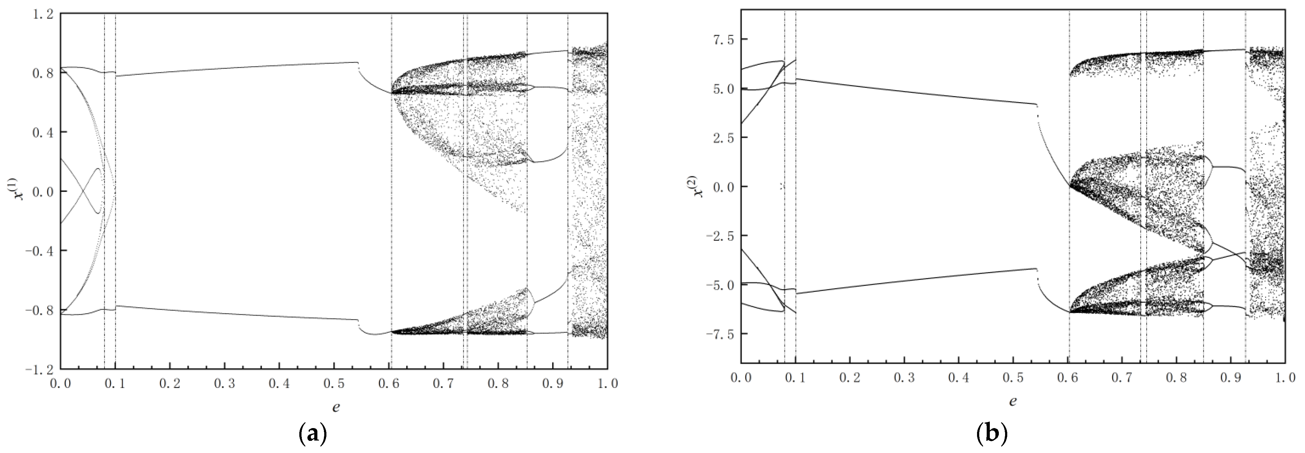
3.1. The Grazing Bifurcation

When the relative phase space trajectories of two vibrators are tangent to the impact boundary, the grazing bifurcation occurs. The appearance of grazing bifurcation will make the motion of the vibrators uncertain, leading to the singularity of Poincaré mapping of the vibrators, and have an essential influence on the formation and evolution of the system dynamic behavior [26]. The grazing bifurcation studies the transition process of the response of the vibrators from the no-meshing periodic motion through the grazing critical state to the impact motion. When the grazing bifurcation occurs, the vibrators may move from the original periodic motion into a different periodic motion of another structure, or into chaos.

3.1.1. Periodic Structure Mutation Induced by Grazing Bifurcation

Figure 6 shows the grazing bifurcation near the restitution coefficient e = 0.0997. When e = 0.0997, the system moves in a period-1, and its mapping structure is p 6532 . The system has an impact on the right impact boundary from its starting point ( x ( 1 ) −0.8008, x ˙ ( 1 ) 5.2444, x ( 2 ) −1.3008, x ˙ ( 2 ) −0.1840, t 85.3515), and has another impact though a local mapping p 2 , then impacts on the left boundary through a global mapping p 3 , and then impacts on the left boundary through a local mapping p 5 . After an impact on the left boundary again, the vibrators then return to the initial point through a symmetric mapping p 6 , forming a periodic trajectory. When the restitution coefficient reaches 0.0998 through the bifurcation point, the mapping structure of the periodic motion of the system changes. The trajectory of vibrators is tangent to the right boundary when it goes through the p 3 mapping from the initial point, and to the left boundary when it goes through the p 6 mapping, so that the mapping structure suddenly changes into the p 63 period-1 mapping structure.

3.1.2. Chaotic Phenomena Induced by Grazing Bifurcation

As shown in Figure 7, the system will enter chaos when e has a small increase after the grazing bifurcation.
In Figure 7, the hollow circle represents the switching point of each mapping, the star represents the starting point of the entire mapping structure, and ” ” and ” ” represent impacts. Figure 7a,b show that when the restitution coefficient e changes from 0.605 to 0.606, the motion of the system evolves from periodic to chaos. The mapping structure of the vibrators system at e = 0.605 is p 63 period-1 motion. Starting from the starting point ( x ( 1 ) −0.6585, x ˙ ( 1 ) 3.4080, x ( 2 ) −1.1585, x ˙ ( 2 ) 6.8180, t 168.4154), it successively goes through p 3 and p 6 mapping, and finally returns to the starting point. When e = 0.606, a new mapping structure p 653 653 appears in the vibrators system, and a unilateral local impact occurs between the mapping p 3 and p 6 , leading to the generation of p 5 , and the entire mapping structure behaves as a complex aperiodic motion. Figure 7c–f show the grazing bifurcation behavior at the restitution coefficient e = 0.742 and e = 0.934, respectively.

3.2. Inverse Bifurcation

Under the condition of large restitution coefficient, the gear has not yet been meshed when the load is reversed, and it collides with the other side after several impacts at the impact boundary of one side, so that a no-meshing impact mapping structure on both sides is formed. Figure 8 shows the operation of the two vibrators at e = 0.854 and e = 0.875; at this time, the system motion produces impact impacts on both sides, and the mapping structures are:
p ( 65363 ) 2 = p 65363 p 65363   and   p 65363
In Figure 8a, when x ( 1 ) = x ( 2 ) + b , it means that the trajectory of the vibrators reaches the right impact boundary (referred to as the right boundary), and when x ( 1 ) = x ( 2 ) b , it means that the trajectory of the vibrators reaches the left impact boundary (referred to as the left boundary). The vibrators periodic movement starts from the starting point ( x ( 1 ) −0.9185, x ˙ ( 1 ) 0.9908, x ( 2 ) −1.4185, x ˙ ( 2 ) 5.3685, t 134.6826), and first reaches the left boundary from the right boundary through mapping p 3 . When reaching the left boundary, it can be seen that the two gears have different speeds, so the impact occurs, resulting in a sudden change in speed. After impact, the gear reaches the right boundary through mapping p 6 , and then returns to the initial state after successively going through mapping p 3 , p 5 , p 6 , p 3 , p 6 , p 3 , p 5 , p 6 , forming a stable period-4 motion. Figure 8b is the phase diagram of the period-4 motion, and Figure 8c is the phase diagram of the motion when the restitution coefficient e = 0.875. It can be seen that when the restitution coefficient increases near this point, the oscillator motion has an inverse bifurcation, and the period-4 motion is converted to period-2 motion.

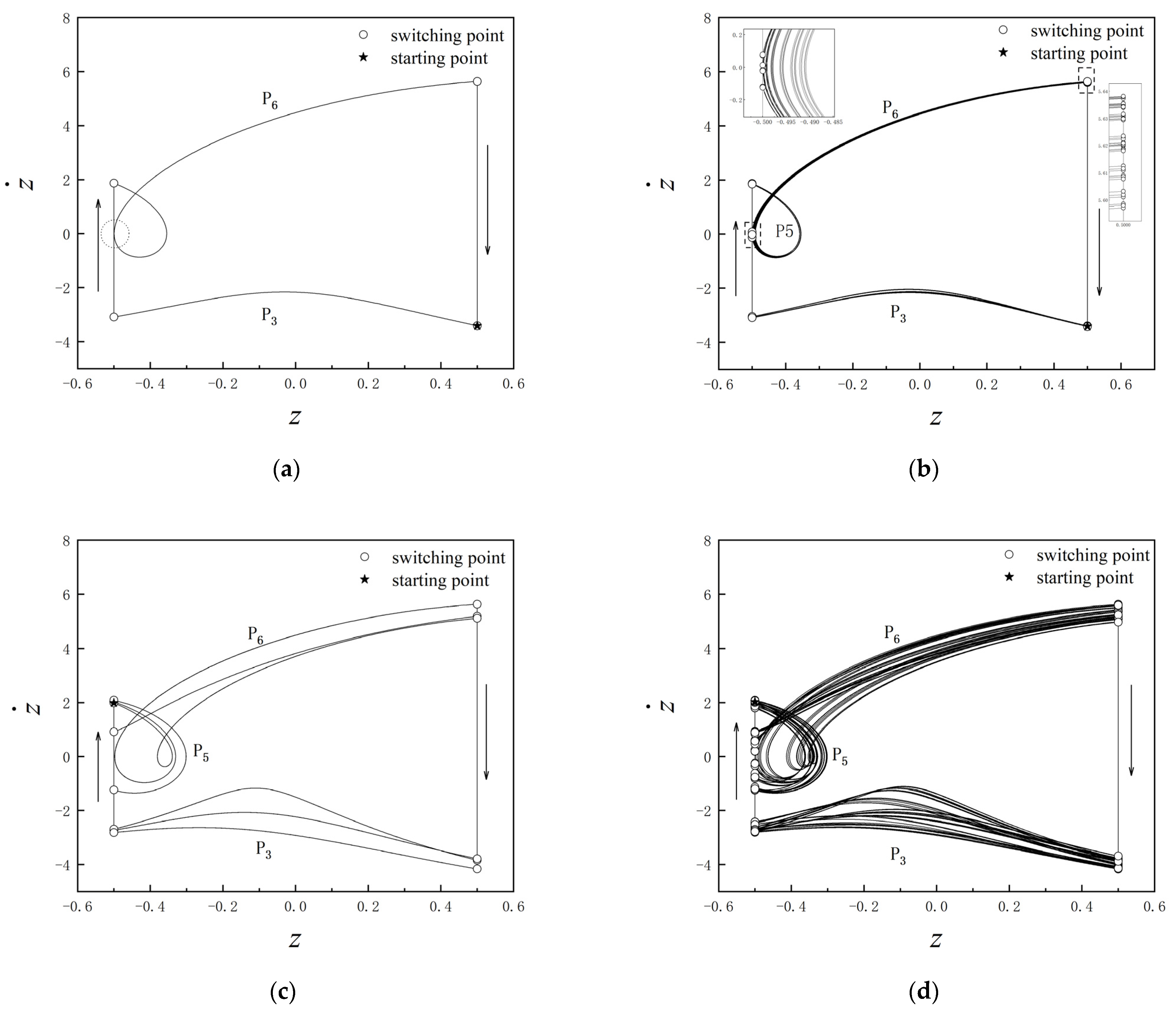
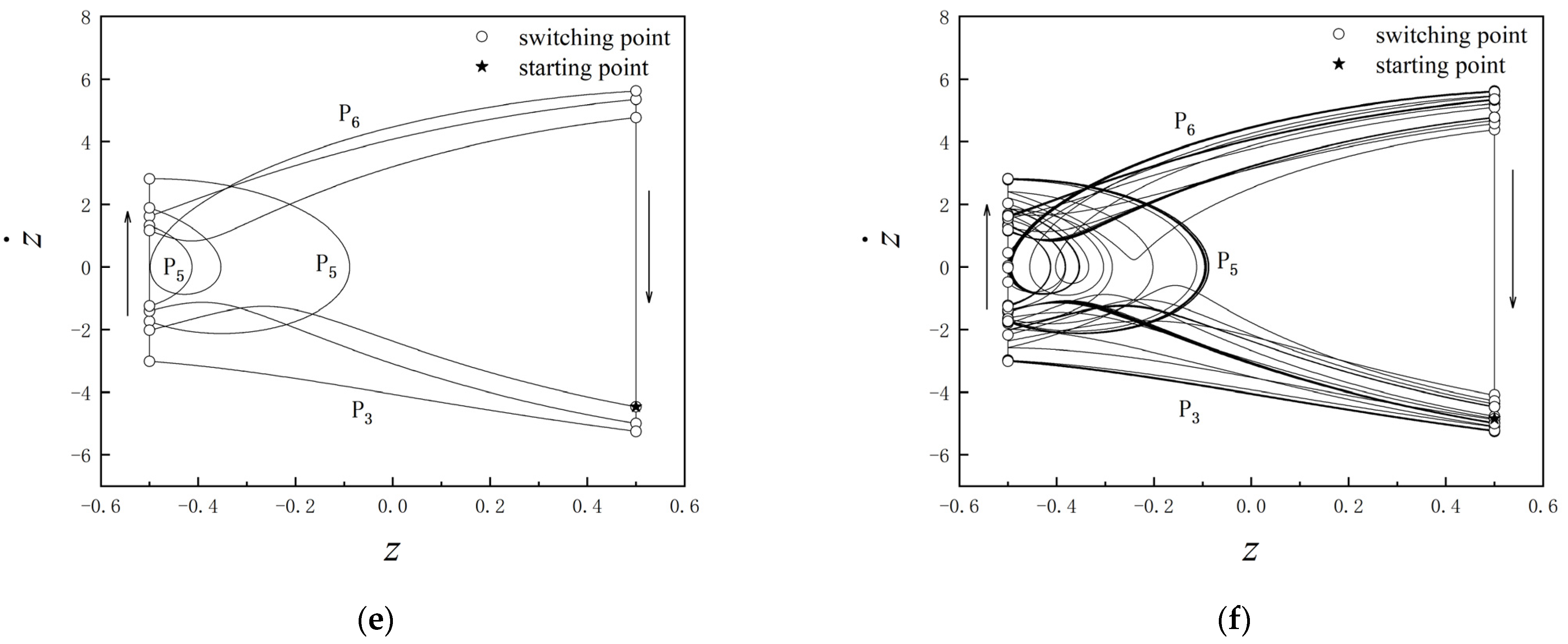
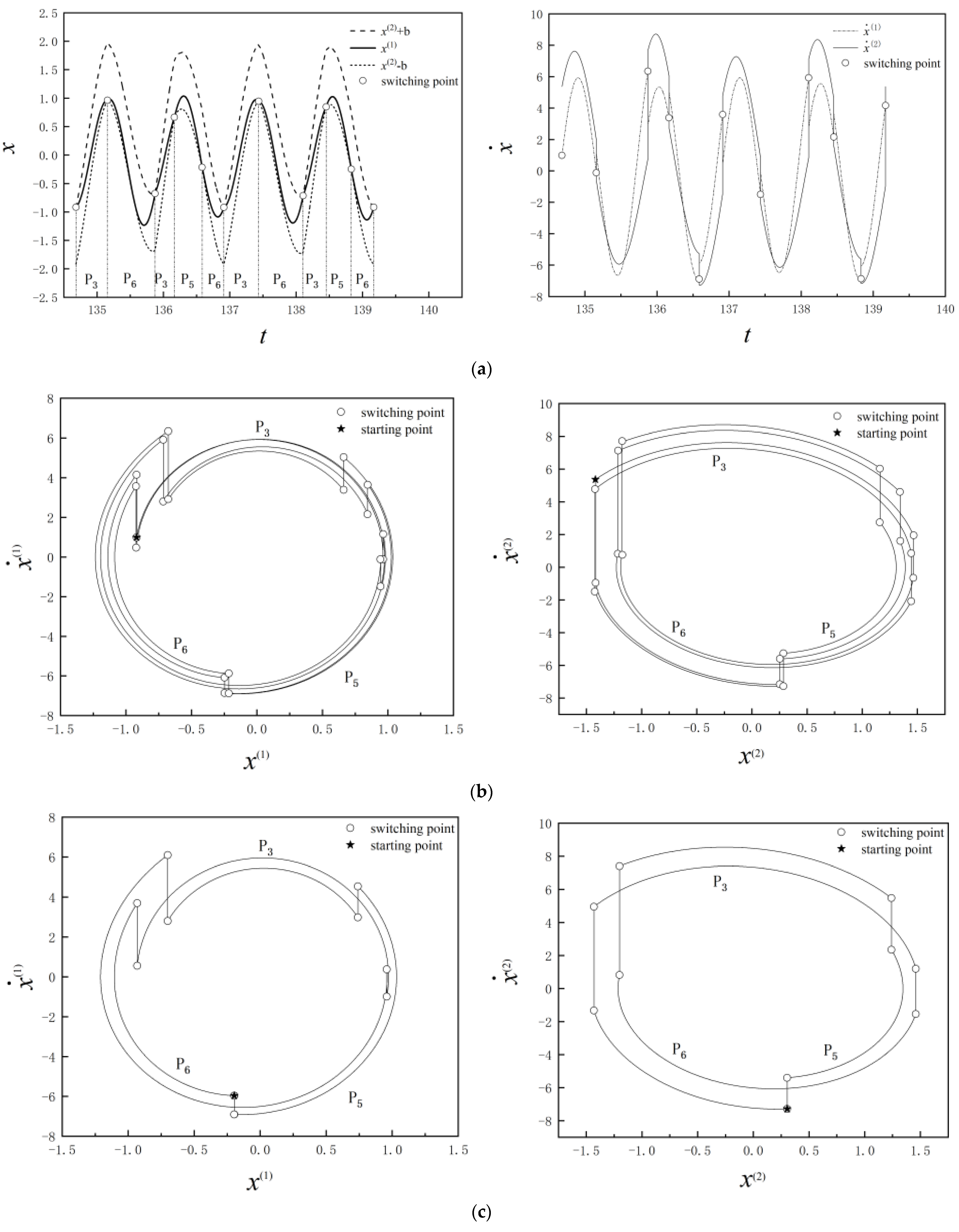
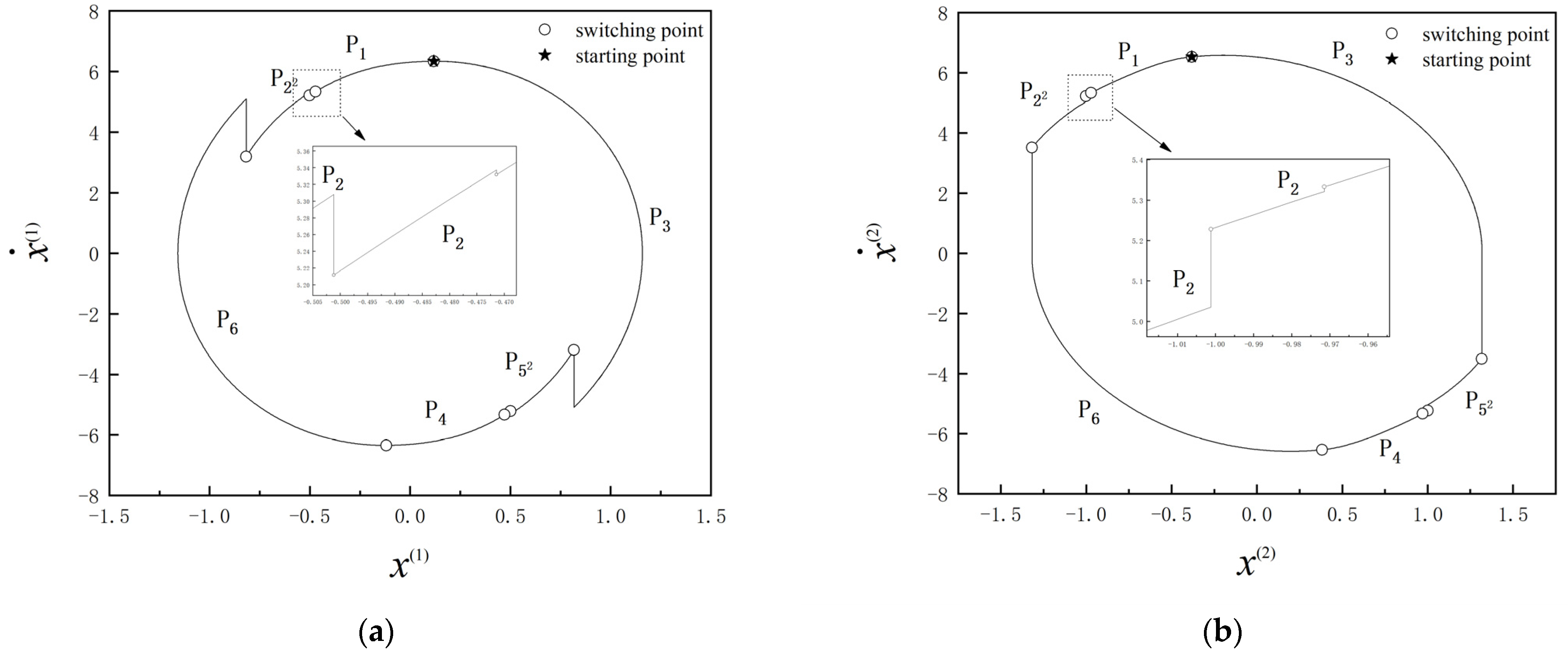
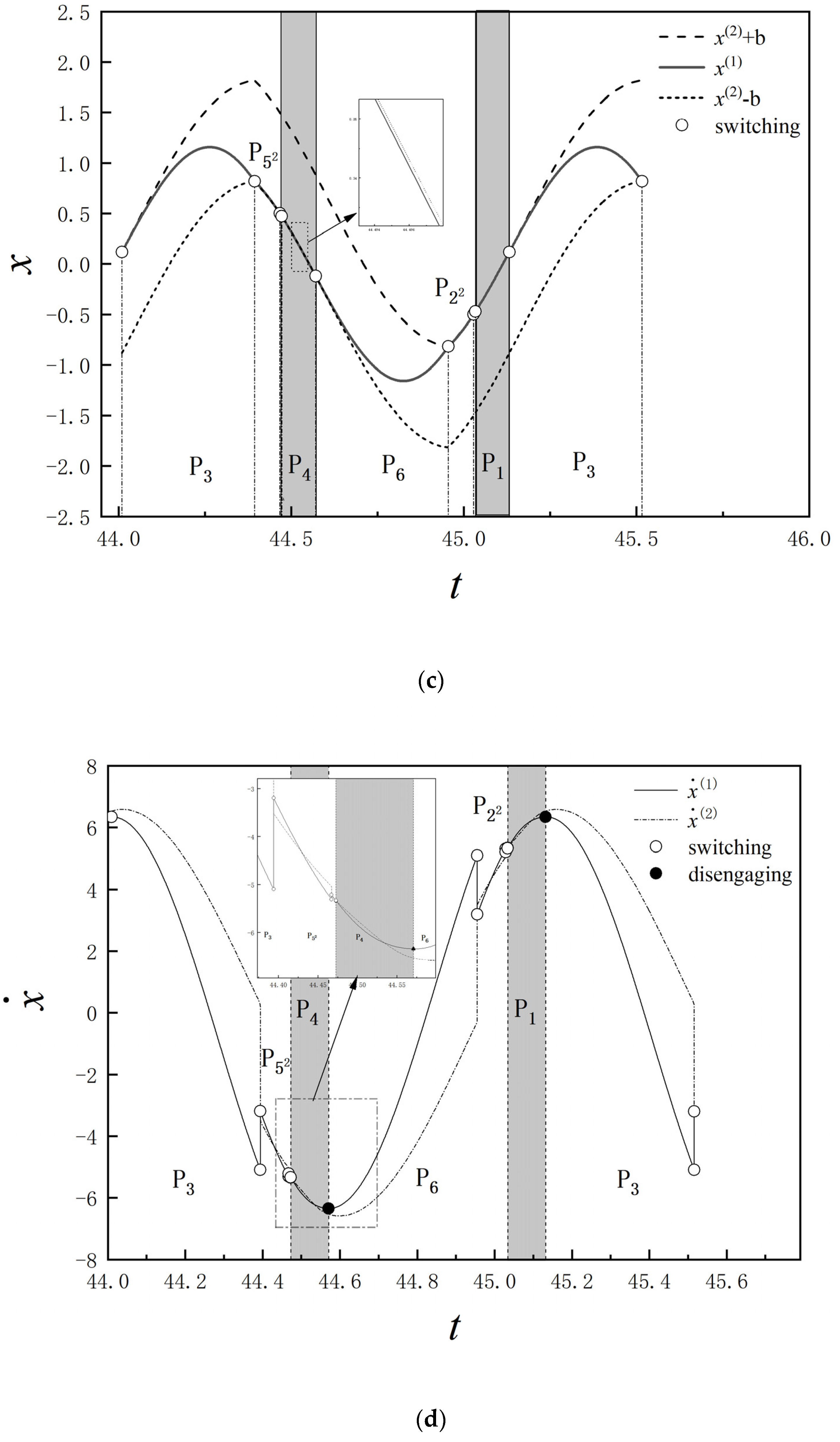
3.3. Impact-Meshing Motion

When the restitution coefficient is relatively small, the energy loss during gear impact is large. After several impacts, the speed of two gears meets the conditions for meshing, and meshing may occur. It is pointed out here that meshing does not necessarily occur if the speed meets the meshing conditions, and there are other requirements for meshing conditions in addition to the speed requirements. See the description of meshing conditions in Section 2.2.2.
Figure 9 shows the periodic motion of the gear vibrators when e = 0.06. The mapping structure of the system is:
p 12 2 645 2 3 = p 1 p 2 2 p 6 p 4 p 5 2 p 3
The starting point of this periodic motion is ( x ( 1 ) 0.1184, x ˙ ( 1 ) 6.3427, x ( 2 ) −0.3816, x ˙ ( 2 ) 6.5333, t 44.0097). After going through the global mapping p 3 , it reaches the left boundary and collides with the left boundary. Then it goes through two local mapping p 5 , making the vibrators reach the meshing conditions. The gray part in the figure is the meshing section. It can be clearly seen from the partial enlarged view that when the gears are meshing x ( 1 ) < x ( 2 ) b , the meshing deformation occurs between the gears during meshing. In the meshing mapping p 4 , there is a flexible coupling of spring and damping between gear 1 and gear 2. After the spring recovers its deformation, the gear is disengaged and enters the next global mapping p 6 . The gear collides with the right boundary through mapping p 6 . Then it goes through two local mapping p 2 . The gear enters the meshing state (the mapping p 1 ), which is the motion state of the system in a period. When the driving force is a simple harmonic force, under low restitution coefficient, the gear may experience several impacts before meshing. When the force is reversed, the gear will disengage and move in reverse with impact and meshing; with the increase in the restitution coefficient, when the load reverses, the gears will collide reversely with the change of the load before they reach the meshing condition after several impacts. Therefore, in the gear transmission with variable loading, low restitution coefficients will make the gears easier to mesh.

4. Conclusions

In this paper, the theory of discontinuous dynamical systems is used to study the nonlinear dynamic behavior of rattling vibration in gear transmission problems. A two-degree-of-freedom vibrator model is established, which considers the meshing stiffness and meshing deformation and uses damping to characterize the energy loss during meshing and the damping resistance of materials. The theory of flow switchability and mapping dynamics are applied to study the model. Research shows:
  • As the coefficient of restitution changes, the grazing bifurcation occurs frequently. The phenomenon of grazing bifurcation in gear transmission system with backlash will lead to complex dynamic behavior of the system, which will directly lead to bifurcations, new periodic mapping structure, and even chaos of the system. It is necessary to select appropriate coefficients to avoid this phenomenon, and the theory of discontinuous dynamical systems is quite suitable for gear systems.
  • Gear pairs with low restitution coefficient are more likely to mesh, that is, gear materials with strong plasticity are more likely to mesh, and the number of impacts before engagement will be significantly reduced. With large restitution coefficient, the speed of the gear pair has difficulty reaching the meshing condition, so it is difficult to mesh. Reasonable selection of gear materials can increase the meshing opportunity as much as possible and reduce the rattling energy loss.
  • Because the gear teeth are elastic-plastic, the introduction of gear meshing stiffness and impact restitution coefficient can more effectively represent the elastic deformation and energy loss in the process of gear impact-meshing motion, which provides a theoretical model for further gear transmission systems with flexible contact considering the more complex multi degree of freedom.

Author Contributions

Conceptualization, Y.L. and S.Q.; methodology, Y.L.; software, Y.L.; validation, Y.L., S.Q. and G.Y.; formal analysis, Y.L.; investigation, S.Q.; resources, Y.L.; data curation, S.Q.; writing—original draft preparation, Y.L. and M.D.; writing—review and editing, Y.L. and M.D.; visualization, S.Q. and M.D.; supervision, Y.J.; project administration, G.Y.; funding acquisition, G.Y. All authors have read and agreed to the published version of the manuscript.

Funding

This research was funded by the National Natural Science Foundation of China (No. 12072089; No. 11972131); the Heilongjiang Key Research and Development Plan (GA21D004) and the Heilongjiang Province Major Scientific and Technological Achievements Transformation Project (No. CG21B010).

Conflicts of Interest

The authors declare no conflict of interest.

References

  1. Pavelko, I.; Pavelko, V. Dynamic properties of aircraft components at real constraints. Aviation 2008, 12, 113–117. [Google Scholar] [CrossRef]
  2. Bruzzone, F.; Rosso, C. Sources of excitation and models for cylindrical gear dynamics: A review. Machines 2020, 8, 37. [Google Scholar] [CrossRef]
  3. Li, M.; Khonsari, M.; Yang, R. Dynamics analysis of torsional vibration induced by clutch and gear set in automatic transmission. Int. J. Automot. Technol. 2018, 19, 473–488. [Google Scholar] [CrossRef]
  4. Amin Al Hajj, M.; Quaglia, G.; Schulz, I.; Qin, Y. Condition-Based Monitoring on High-Precision Gearbox for Robotic Applications. Shock Vib. 2022, 2022, 6653723. [Google Scholar] [CrossRef]
  5. He, X.; Zhang, H. Dynamics modelling of transmission gear rattle and analysis on influence factors. IOP Conf. Ser. Mater. Sci. Eng. 2018, 307, 012050. [Google Scholar] [CrossRef]
  6. Dawei, L.; Zhenzhen, L.; Guohao, Z. Rattle dynamics of noncircular face gear under multifrequency parametric excitation. Mech. Sci. 2021, 12, 361–373. [Google Scholar]
  7. Rigaud, E.; Perret-Liaudet, J. Investigation of gear rattle noise including visualization of vibro-impact regimes. J. Sound Vib. 2020, 467, 115026. [Google Scholar] [CrossRef]
  8. Dong, G.; Yi, Z.; Yi, Z.; Yawen, W.; Fangchao, C.; Xiaohui, S. Numerical and experimental study of gear rattle based on a refined dynamic model. Appl. Acoust. 2022, 185, 108407. [Google Scholar]
  9. Mingxuan, L.; Ying, W.; Tian, Z. Optimization on nonlinear dynamics of gear rattle in automotive transmission system. Shock Vib. 2019, 2019, 4056204. [Google Scholar]
  10. Zhang, J.; Liu, D.; Yu, H. Experimental and numerical analysis for the transmission gear rattle in a power-split hybrid electric vehicle. Int. J. Veh. Des. 2017, 74, 1–18. [Google Scholar] [CrossRef]
  11. Dong, H.; Shen, Y.; Liu, X. Research on the rattling in gear system. In Proceedings of the International Conference on Mechanical Transmissions, Chongqing, China, 26–30 September 2006; Volume 1. [Google Scholar]
  12. Yun, Y.J.; Iljae, L. Nonlinear analysis of Vibro-Impacts for unloaded gear pairs with various excitations and system parameters. J. Vib. Acoust. 2014, 136, 031010. [Google Scholar] [CrossRef]
  13. Han, R.; Luo, A.; Deng, W. Chaotic motion of a horizontal impact pair. J. Sound Vib. 1995, 181, 231–250. [Google Scholar] [CrossRef]
  14. Luo, A.; Menon, S. Global chaos in a periodically forced, linear system with a dead-zone restoring force. Chaos Soliton. Fract. 2004, 19, 1189–1199. [Google Scholar] [CrossRef]
  15. Luo, A. A theory for non-smooth dynamic systems on the connectable domains. Commun. Nonlinear Sci. Numer. Simul. 2005, 10, 1–55. [Google Scholar] [CrossRef] [Green Version]
  16. Luo, A.C.J.; Rapp, B.M. Flow switchability and periodic motions in a periodically forced, discontinuous dynamical system. Nonlinear Anal. Real World Appl. 2008, 10, 3028–3044. [Google Scholar] [CrossRef]
  17. Luo, A.; O’Connor, D. Impacting chatter and stick in a transmission system with two oscillators. J. Multi-Body Dyn. 2009, 223, 159–188. [Google Scholar] [CrossRef]
  18. Guo, S.; Luo, A. An analytical prediction of periodic motions in a discontinuous dynamical system. J. Vib. Test. Syst. Dyn. 2020, 4, 377–388. [Google Scholar] [CrossRef]
  19. Xu, Y.; Chen, Z.; Luo, A.C.J. On bifurcation trees of period-1 to period-2 motions in a nonlinear Jeffcott rotor system. Int. J. Mech. Sci. 2019, 160, 429–450. [Google Scholar] [CrossRef]
  20. Yeyin, X.; Luo, A.C.J. Period-1 to period-8 motions in a nonlinear jeffcott rotor system. J. Comput. Nonlin. Dyn. 2020, 15, 091012. [Google Scholar]
  21. Xu, Y.; Chen, Z.; Luo, A.C.J. Period-1 motion to chaos in a nonlinear flexible rotor system. Int. J. Bifurcat. Chaos 2020, 30, 2050077. [Google Scholar] [CrossRef]
  22. Guo, S.; Luo, A.C.J. On existence and bifurcations of periodic motions in discontinuous dynamical systems. Int. J. Bifurcat. Chaos 2021, 31, 2150063. [Google Scholar] [CrossRef]
  23. Luo, A.; Liu, C. Analytical dynamics of a discontinuous dynamical system with a hyperbolic boundary. J. Vib. Test. Syst. Dyn. 2021, 5, 285–319. [Google Scholar] [CrossRef]
  24. Luo, A. The mapping dynamics of periodic motions for a three-piecewise linear system under a periodic excitation. J. Sound Vib. 2005, 283, 723–748. [Google Scholar] [CrossRef]
  25. Luo, A.C. On the differential geometry of flows in nonlinear dynamical systems. J. Comput. Nonlinear Dyn. 2008, 3, 021104. [Google Scholar]
  26. Yin, S.; Shen, Y.; Wen, G.; Xu, H. Analytical determination for degenerate grazing bifurcation points in the single-degree-of-freedom impact oscillator. Nonlinear Dynam. 2017, 90, 443–456. [Google Scholar] [CrossRef]
Figure 1. Diagram of gear pair with backlash.
Machines 10 01112 g001
Figure 2. Vibration-impact model of gear tooth with clearance.
Machines 10 01112 g002
Figure 3. Discontinuous boundary and domain.
Machines 10 01112 g003
Figure 4. The mapping structures.
Machines 10 01112 g004
Figure 5. Bifurcation diagram of gear system. (a) Switching displacement of gear 1 (b) Switching displacement of gear 2.
Machines 10 01112 g005
Figure 6. Periodic structure mutation. (a) e = 0.0997, (b) e = 0.0998.
Machines 10 01112 g006
Figure 7. The grazing bifurcation. (a) e = 0.605, (b) e = 0.606, (c) e = 0.742, (d) e = 0.743, (e) e = 0.934, (f) e = 0.935.
Machines 10 01112 g007aMachines 10 01112 g007b
Figure 8. Inverse bifurcation. (a) e = 0.854, (b) e = 0.854, (c) e = 0.875.
Machines 10 01112 g008
Figure 9. Phase plane of the gear motion at e = 0.06. (a) Phase plane of gear 1, (b) Phase plane of gear 2, (c) Displacement-time diagram, (d) Velocity-time diagram.
Machines 10 01112 g009aMachines 10 01112 g009b
Table 1. Parameters of model.
Dimensionless CoefficientsSymbolValue
Equivalent mass of gear 1 m 1 2
Equivalent mass of gear 2 m 2 1
Support damping of gear 1 r 1 0.6
Support damping of gear 2 r 2 0.6
Meshing damping r 1
Support stiffness of gear 2 k 1 30
Support stiffness of gear 2 k 2 20
Meshing stiffness k 1000
Amplitude of driving force F 50
Excitation frequency ω 5.6
Backlash of gear pair2b1
Publisher’s Note: MDPI stays neutral with regard to jurisdictional claims in published maps and institutional affiliations.

