1. Introduction
In the measurement site of aerospace, it is necessary to perform precise measurements of large-scale assemblies [
1]. A space mast is a widely used aerospace structure that plays an important role in observation, communication, space science, deep space exploration, and other activities [
2,
3]. The accuracy and stability of large space masts will directly affect the service performance of large aerospace systems, which puts forward a high requirement for measurement technology in large scenes. In recent years, various types of large-scale measurement equipment have been developed, such as laser trackers [
4], iGPS [
5], machine vision [
6], and wMPS [
7]. Compared with other equipment, a laser tracker has a wide measurement range and high measurement accuracy and is widely used in manufacturing sites.
Laser multilateration is a mature measurement method that mainly uses multiple laser tracker stations to determine the coordinates of target points. Compared with the measurement of a single laser tracker, laser multilateration only uses the distance measurement value, which can obtain higher measurement accuracy [
8]. However, it is difficult to choose the positions and layout of multi-station laser trackers in large spaces, which requires the study of laser tracker station distribution.
Previous studies have been carried out to determine the layout of laser trackers under different conditions. For the multilateral layout of four laser trackers, Takatsuji et al. [
9,
10] proposed a layout principle wherein four stations cannot be on the same plane. Wang et al. [
11] developed a GPU-accelerated light detection algorithm and realized the constrained layout optimization of multiple laser trackers by mode search, genetic algorithm, and particle swarm optimization. Aguado et al. [
12] studied the influence of the spatial angle between laser trackers, the distance, and the visibility of the target point on the measurement uncertainty of the laser tracker, which reduces the volumetric error of the machine tool. Hu et al. [
13] simulated and optimized the layout of the laser tracker based on the proposed calibration method, and the result showed that the tri-rectangular pyramid layout was the best layout and could improve measurement accuracy. Zhang et al. [
14] studied the in situ measurement method of a large thin-wall tank’s ring seam welding and optimized the layout of laser trackers and ERS points using a genetic algorithm. Ren et al. [
15] proposed a grid-based placement optimization based on a genetic algorithm and realized the global optimization through the combination of global and local search, which reduced the requirements of the algorithm in the initial layout. Wang et al. [
16] proposed an optimization method using the positional dilution of precision (PDOP) as the evaluation factor and realized the evaluation of the optimal laser tracker station by analyzing the distribution law of PDOP at different positions.
In this paper, we proposed a large-scale measurement layout optimization method based on an improved cellular genetic algorithm. Firstly, the measurement uncertainty of spatial points by laser multilateration is obtained. Then, aiming at the problems of light path occlusion and target ball measurement error, the visibility constraint of the laser tracker and the incident angle constraint of the target ball are established. Finally, based on the above constraints, the improved cellular genetic algorithm is adopted to search for the best station distributions in space. The results show that the proposed method can effectively improve measurement accuracy and optimize layout efficiency.
2. Laser Multilateration Measurement Uncertainty
2.1. Measurement Principle of Laser Multilateration
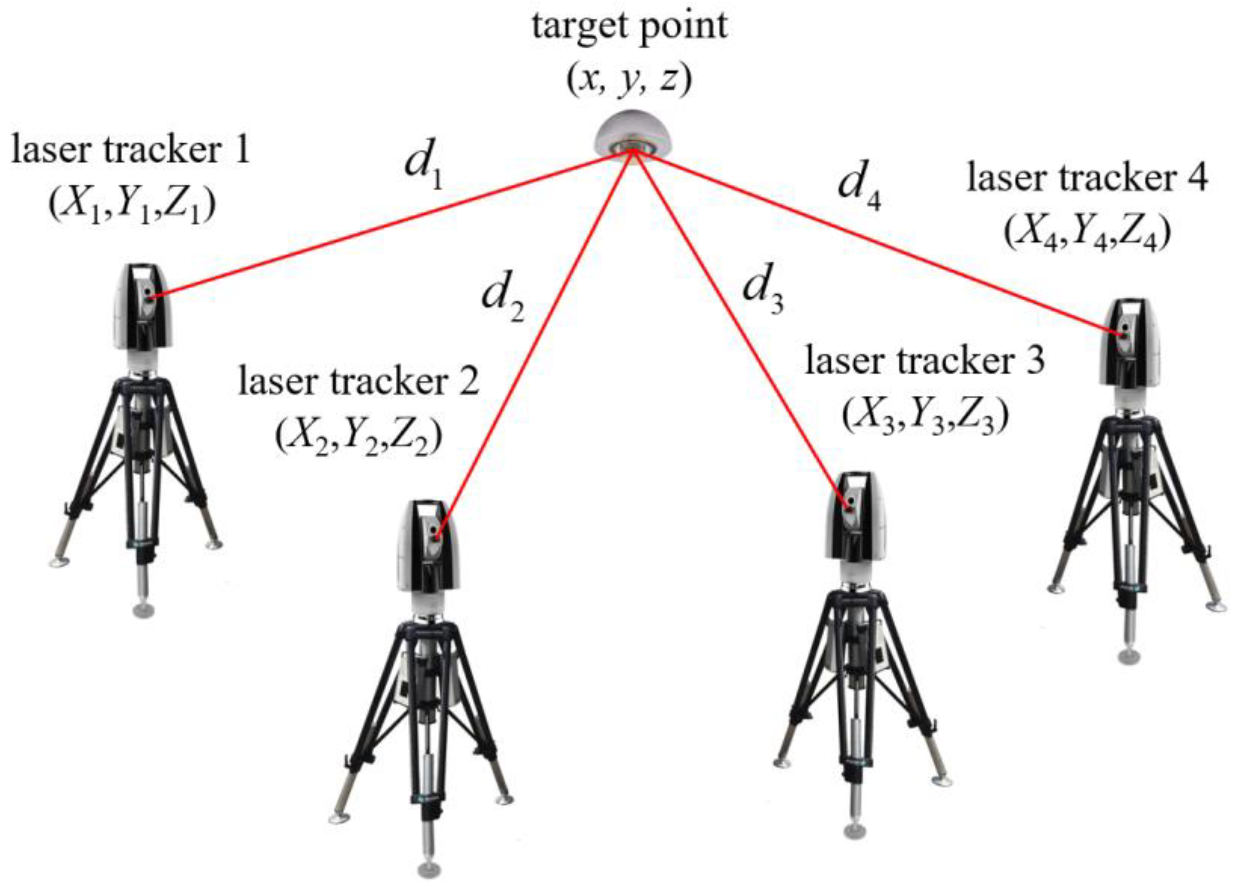
The principle of laser multilateration is shown in
Figure 1. Four or more laser trackers are established in space, and the three-dimensional coordinates of the target point are calculated only by the distance from each station to the target ball [
17].
For the four laser tracker stations
, control them to track the same target ball
, then the distance
from each station to the reflective target ball can be obtained. Tour distance equations can be established as follows.
To obtain the coordinate value of the target point, the equations above can be converted into the residual error
, which is the difference between the calculated value and the measured value. As shown in formula (2),
are the calculated station coordinates with errors, and
is the measured distance value with error. The problem is then transformed into solving the minimum residual sum
, which can be solved by using the Gauss–Newton method, trust region method, Levenberg–Marquardt method [
18], and other methods.
2.2. Spatial Measurement Uncertainty of Target Point
A variety of error factors will be introduced in the measurement process of the laser tracker, which will affect the spatial measurement uncertainty of the target point. For the laser multilateration, the main error sources in the measurement process are the distance measuring error of the laser tracker and the station coordinate error caused by self-calibration. For the spatial point measurement of laser trackers, the input quantity is , and the unknown quantity is the three-dimensional coordinates of the spatial point .
The GUM method is adopted to evaluate the uncertainty of laser multilateration measurement [
19]. The input uncertainty is the distance measuring uncertainty of the corresponding laser tracker
and the station coordinate uncertainty
. Since each uncertainty is independent, the final input uncertainty matrix
can be expressed in the form of a diagonal matrix.
The output uncertainty matrix
can be obtained by calculating the sensitivity matrix
.
Since the laser multilateration is solved by nonlinear optimization, the sensitivity matrix
between the input and output cannot be obtained directly by derivation. When
reaches its minimum value, its derivative of
is 0, so the sensitivity matrix can be solved by using implicit functions.
Finally, the output uncertainty matrix of the target point can be obtained.
For the target point, its total spatial uncertainty can be expressed as follows.
3. Constraint Conditions for Layout Optimization
3.1. Visibility Constraint
When there is an occlusion between the laser tracker and the reflective target ball, the laser beam will be interrupted, resulting in measurement failure. Therefore, it is necessary to detect the occlusion in the environment and determine whether it will block the laser light path. We simplified the occlusion into a k-DOPs bounding box to achieve the rapid line of sight detection of the laser tracker and return the judgment result of intersection judgment.
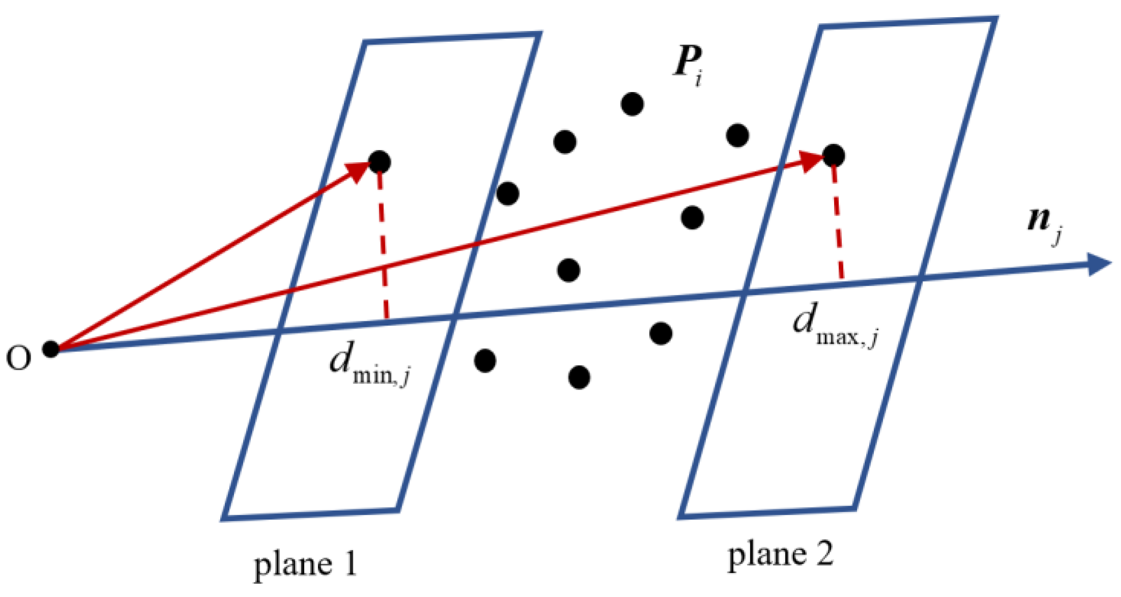
In three-dimensional space, a k-DOPs bounding box is a convex polyhedron surrounded by
pairs of parallel planes. Each pair of planes is determined by a fixed normal direction
and can closely surround all mesh vertices of the object. Let the vertex on the object be
, as shown in
Figure 2.
Calculate the dot product of any point in the set and the normal direction by formula (10) and take the maximum and minimum values for all results.
Then, each group of parallel planes can be uniquely determined as the following mathematical expression. For the occlusion in the measurement space, the parameters of the corresponding k-DOPs bounding box can be calculated before layout optimization and can be reused in subsequent intersection judgment to avoid repeated calculations.
The projection interval
of the laser beam from the laser tracker to the reflective target ball on each plane pair is expressed as the following formula.
where
is the selected laser tracker position and
is the target ball position.
The visibility judgment is performed according to formula (13), where
is the minimum value among the maximum values of all projection intervals, and
is the maximum value among the minimum values of all projection intervals.
When Equation (13) holds, it is considered that the projection interval coincides, which means there is an intersection between the laser beam and the k-DOPs bounding box.
3.2. Incident Angle Constraint
The reflection ball is an important part of laser distance measurement. If the angle of the incident laser beam is too large, the measurement accuracy will be greatly affected. Generally, the target ball is manually rotated to align with the laser emission point, but this process requires repetitive operation and will introduce a large target ball eccentricity error. Therefore, it is necessary to limit the incidence angle of the multiple laser beams so that when multiple stations aim at a reflective target ball simultaneously, they all have a relatively small incidence angle.
For the reflective target ball with the maximum incident angle of
, the incident angle constraint is demonstrated in
Figure 3. The incident laser beam needs to be inside the cone with the center of the target ball as the vertex and the apex angle not exceeding
.
A separate coordinate system can be established for each target ball, with the center of the target ball as the origin of the coordinate system. The normal direction of the target ball coordinate system is expressed as follows.
For all the laser beam vectors, the relative angle between them and the normal vector
needs to be smaller than the maximum angle
. The vector from the selected target ball center
to the laser tracker station
can be expressed as the standard vector, shown in the following formula.
The cosine of the angle formed by each standard incident vector and the target normal vector is described as follows.
To ensure that the laser incident angle of each station is within the given range, the angle constraints can be transformed into a constrained optimization problem.
An adaptive weight is introduced based on the above function. For angles close to or larger than
, a larger weight is given so that the final optimized incident angle of the multiple stations is relatively small.
The optimal angle between the normal vector and each incident vector is calculated by using the least-squares method. If the results are all less than , it is considered that the point meets the incident angle constraint, and the simultaneous measurement of the multiple laser trackers can be realized.
4. Layout Optimization Based on an Improved Cellular Genetic Algorithm
The cellular genetic algorithm (CGA) is an evolutionary algorithm that combines a cellular automaton and a genetic algorithm. It enhances the local search ability of the traditional genetic algorithm and ensures a good balance between the global search and local optimization [
20].
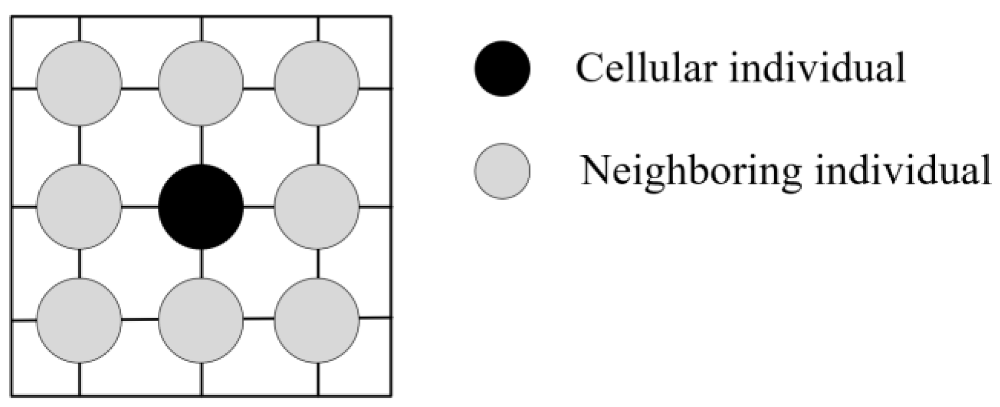
The process of the CGA is as follows. Each genetic individual is set as a cell, and the genetic population is mapped into a two-dimensional cellular space, as shown in
Figure 4. During iteration, each cellular individual is selected, crossed, and mutated with its surrounding neighboring individual to generate new individuals. After that, compare the fitness of the new individual with that of the initial individual. If the fitness is optimized, replace the central individual with the new individual, otherwise, keep the original individual.
In order to ensure the balance between the global search and local optimization of the CGA, the number of times that each cellular individual is not updated in the iterative process is recorded. When the individual has not been updated for a long time, the size of the crossover and mutation operators is adaptively changed, thereby helping the algorithm to jump out of the local optimal solution. For each cellular individual, the corresponding crossover and mutation operators are as follows.
where
and
are the initial crossover and mutation operators, respectively;
is the number of times that each cell has not been updated;
and
are adjustable constants;
is the current iteration number; and
is the total number of iterations.
Based on the improved CGA, the layout optimization of multiple laser trackers in a large-scale scene is carried out. For the
points that need to be measured in space, the average uncertainty of all points is used as the fitness function of layout optimization.
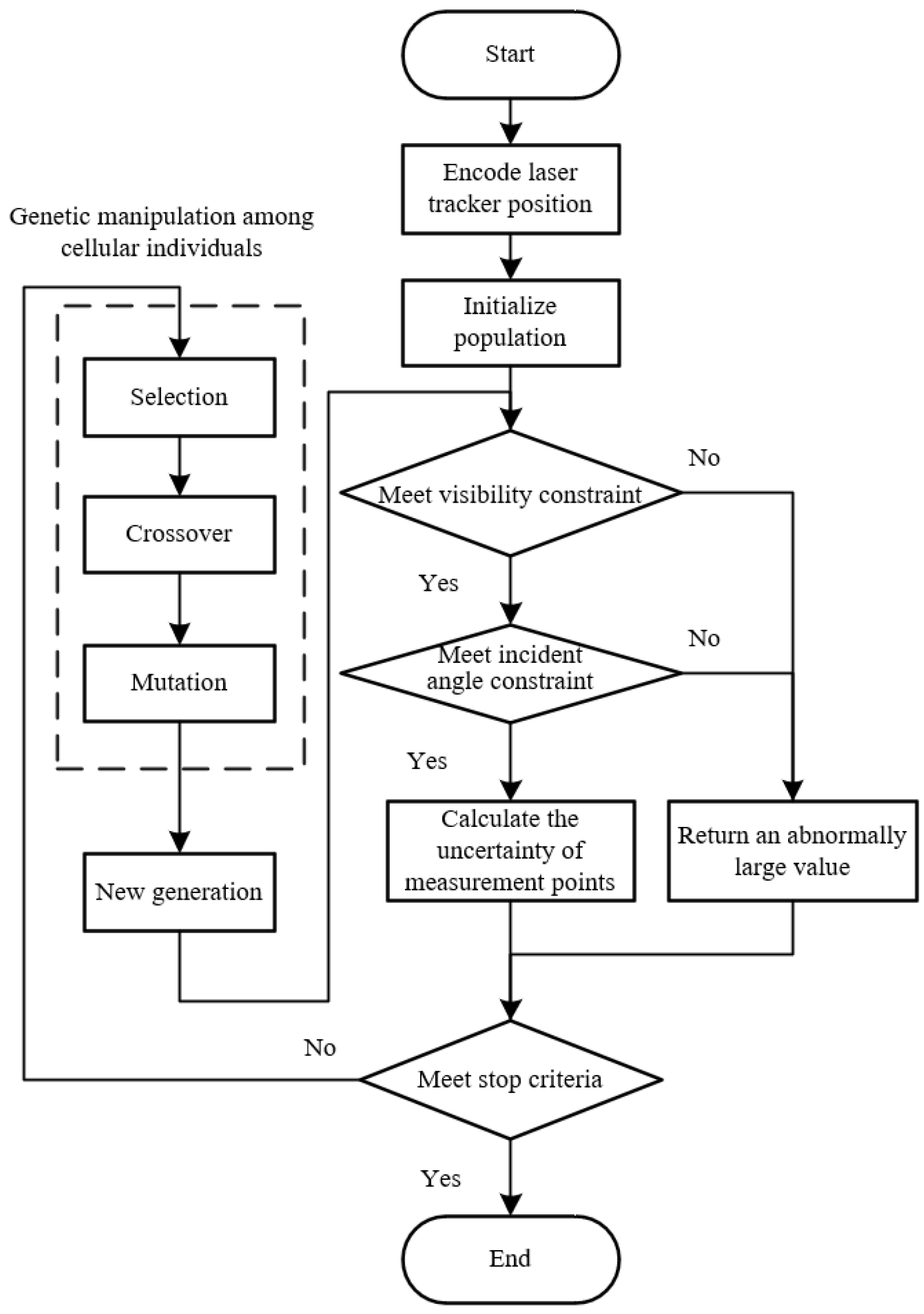
The layout optimization process based on the improved CGA is shown in
Figure 5. First, the position of each laser tracker is encoded and the population is initialized. Second, the visibility constraint and the incident angle constraint are taken as the judgment conditions. If the constraint conditions are not satisfied, the fitness function of the individual is set to an abnormally large value, so that the individual is eliminated in the next iteration loop. Last, the optimal layout that meets the measurement requirements is obtained by genetic operation between the cellular individual and the neighboring individual.
5. Experiment and Analysis
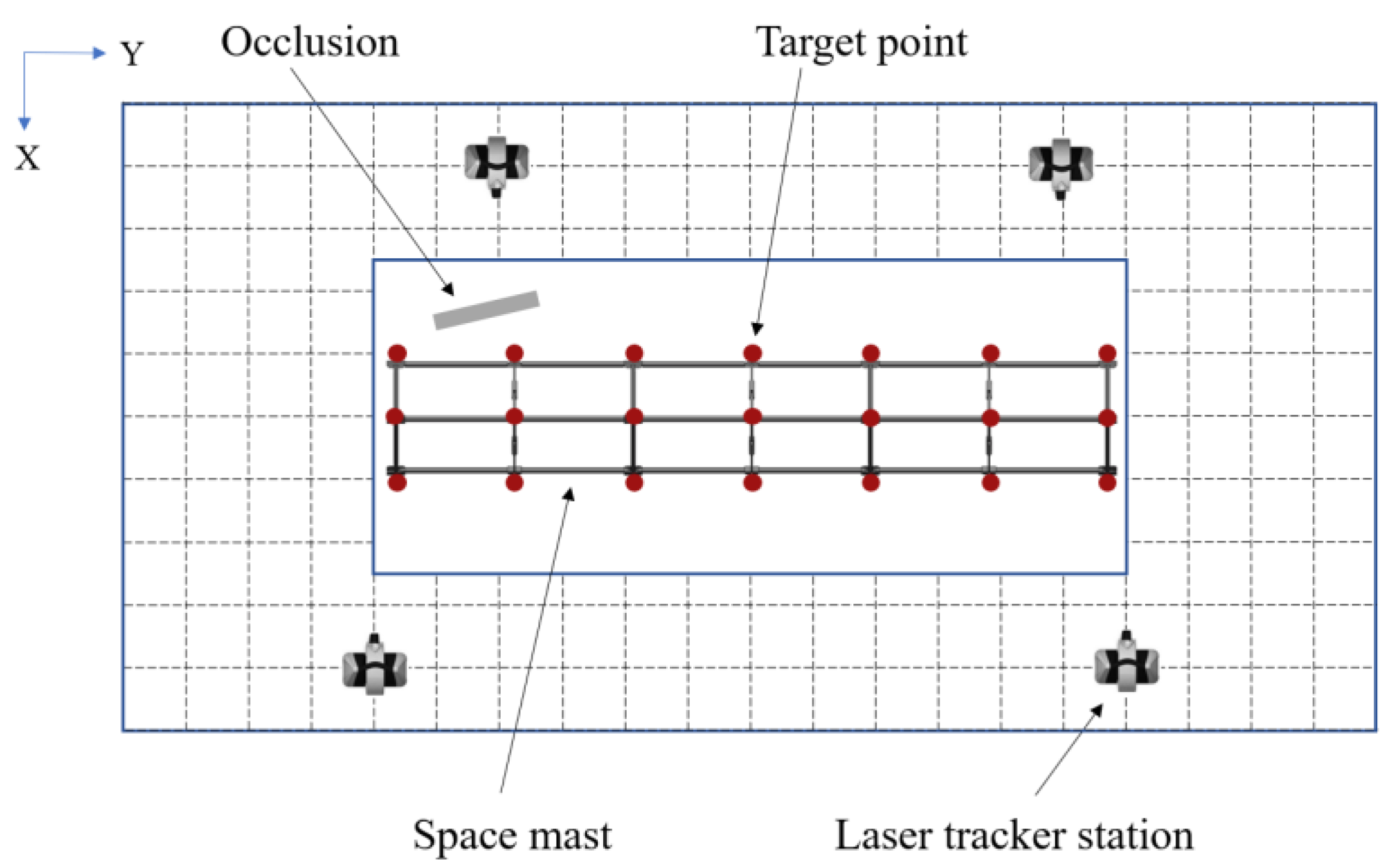
In order to verify the effectiveness of the above layout optimization algorithm, a simulation experiment was carried out to compare the measurement uncertainty of target points before and after layout optimization in large-scale measurement areas. In order to measure the large space mast in the aerospace manufacturing site, 21 target points are set up in the measurement area, as shown in
Figure 6. Set the overall space to
and arrange a measurement area of
in the middle, with a height not higher than
. Arrange a rectangular block as the occlusion in the measurement area, and its overall size is
. In order to improve the efficiency of the layout optimization, the entire measurement space is divided into discrete grids, and each grid point corresponds to a feasible position of the laser tracker. Considering the actual cost, a total of four laser trackers are used to measure the target points. The maximum incident angle of the reflective target ball at each measurement point is
.
The distance measurement uncertainty of the laser tracker is mainly caused by linear measurement error, ambient temperature variation, and repeated measurements, and is set to , where l is the measurement length in meters. As for the station coordinate uncertainty, it is mainly determined by the self-calibration accuracy, and the uncertainty of each coordinate value is set to . The measurement uncertainty of the selected points can then be calculated by the above uncertainty using the GUM method.
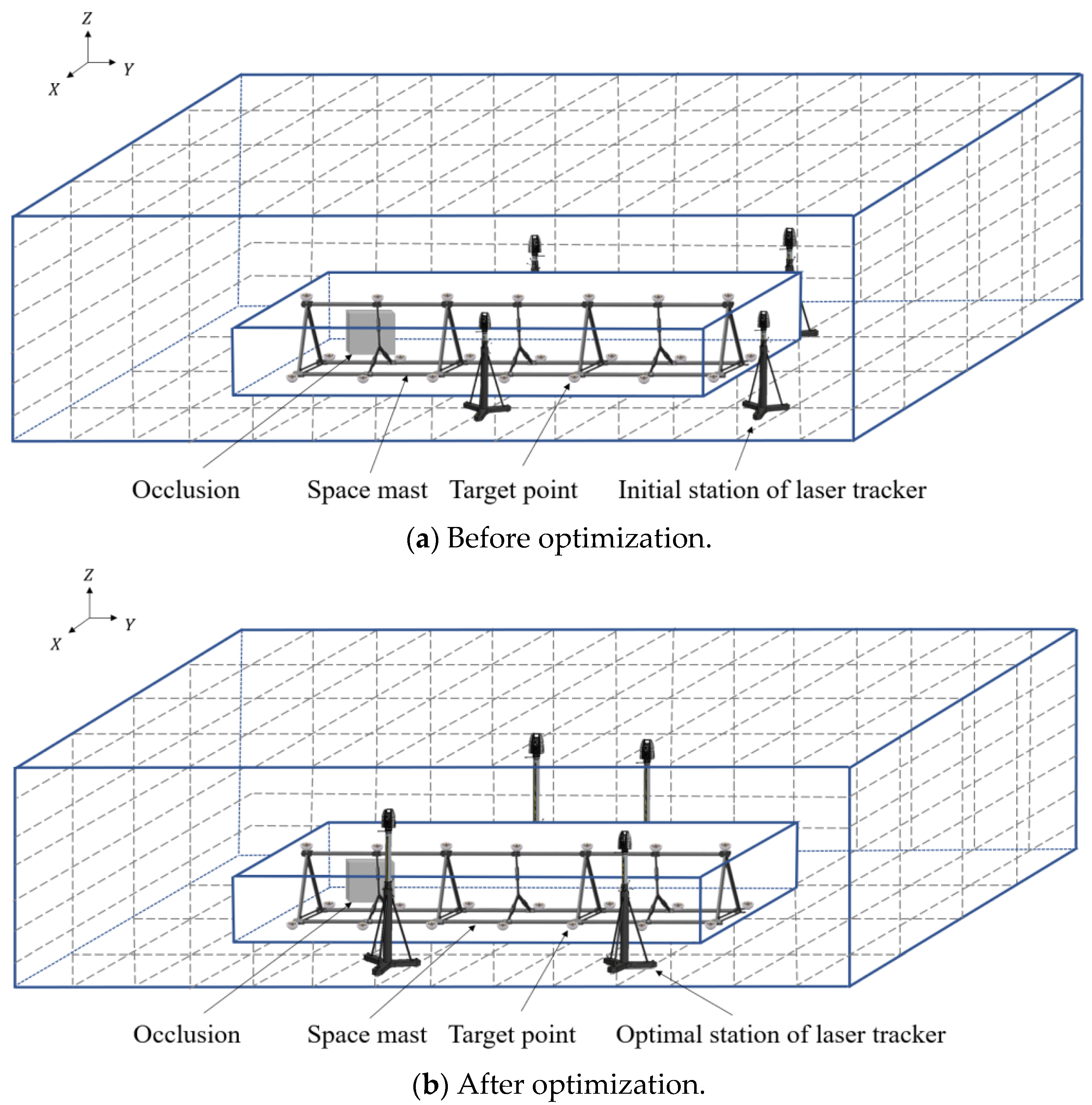
The four laser trackers are evenly distributed in space and used as the layout before optimization. Afterwards, the improved CGA is used to solve the spatial optimization layout. The size of the population is set to 50, the number of iterations is 50, and the initial crossover and mutation factors are 0.8 and 0.05. For the existing occlusion, an 18-DOPS bounding box is used to simplify the model, and the normal vectors of the corresponding plane pairs are
. Finally, the optimal layout position of the laser trackers under the constraints is obtained, and the layout positions of the laser trackers before and after optimization are shown in
Figure 7. The spatial coordinate values of the laser trackers before and after the layout optimization are shown in
Table 1.
Before optimization, there are 11 points that do not meet the constraints. After optimization, all the measurement points can meet the constraints. Ten measurement points that meet the constraints before and after optimization are selected to compare the measurement uncertainty before and after optimization, as shown in
Figure 8. The overall average uncertainty of the target points decreases from
to
after applying the improved CGA. The measurement uncertainty of most points has been significantly reduced, indicating that the optimized layout method can effectively improve measurement accuracy and is suitable for large-scale measurement scenarios with constraints.
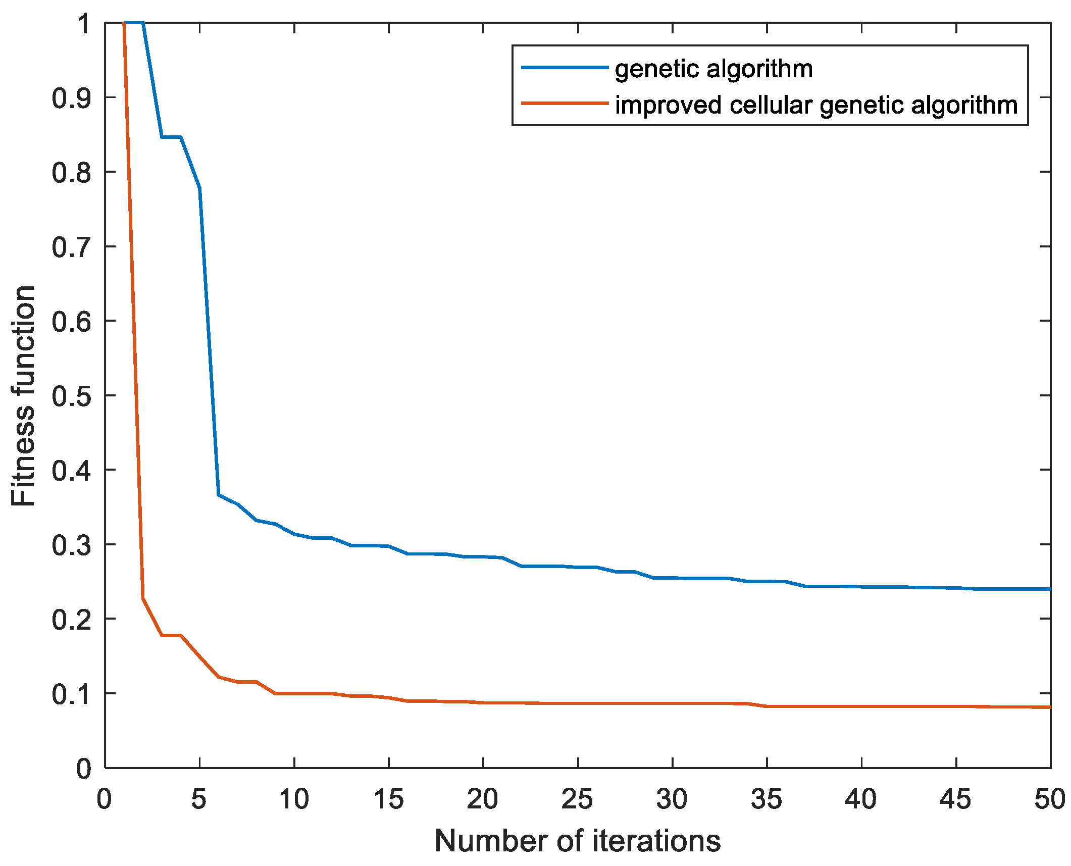
In order to compare the performance of the improved CGA and traditional GA, the same initial conditions and parameters are used to calculate the normalized convergence results, as shown in
Figure 9. Compared with GA, the improved CGA has faster convergence speed and lower fitness. Moreover, the result indicates that the average uncertainty of the measurement points obtained by the improved CGA is lower than that of GA, indicating that the improved CGA algorithm has better global optimization ability and can obtain a better layout position of laser trackers.
6. Conclusions
In this paper, an improved cellular genetic algorithm is proposed to optimize the layout of laser tracker stations in a large-scale multilateral measurement scene. Firstly, the occlusion is simplified by using the k-DOPS bounding box to realize fast intersection detection between the laser beam and the occlusion. Secondly, an adaptive algorithm for adjusting the incident angle of the target ball is proposed to satisfy the constraints of the simultaneous incidence of multiple laser beams. Finally, an improved cellular genetic algorithm is used to optimize the layout of multiple laser tracker stations. The results show that the optimized layout can ensure the full coverage of the measurement points and reduce the overall measurement uncertainty, showing the feasibility and effectiveness of the proposed method. Compared with the traditional genetic algorithm, the improved cellular genetic algorithm improves the optimization accuracy and convergence speed and can provide an effective laser tracker station layout.
