Article

Damping Characteristics of Cantilever Beam with Obstacle Grid Particle Dampers

1
School of Energy Science and Engineering, Harbin Institute of Technology, Harbin 150006, China
2
School of Energy and Power, Jiangsu University of Science and Technology, Zhenjiang 212114, China
*
Author to whom correspondence should be addressed.
Machines 2022, 10(11), 989; https://doi.org/10.3390/machines10110989
Submission received: 24 September 2022 / Revised: 24 October 2022 / Accepted: 26 October 2022 / Published: 29 October 2022
(This article belongs to the Special Issue Low-Frequency Vibration Control with Advanced Technologies)

Abstract

:
In order to understand the damping effect and energy dissipation mechanism of the obstacle grid particle dampers, we conduct experimental and simulated studies. In this paper, the obstacle grid particle dampers are applied to the cantilever beam structure. The effect of filling ratio, particle size, particle material and excitation amplitude of the obstacle grid particle damper on the vibration characteristics of the cantilever beam is studied experimentally and compared with the conventional particle damper for damping effect. A simulation model of the particle damper was developed and experimentally validated using the discrete element method. The experimental results show that the vibration acceleration response of the obstacle grid particle damper decreases by 10.4 dB compared with the conventional particle damper at 90% filling ratio. The obstacle grid particle damper increases the area of energy transfer between the external vibration energy and the particles. It makes the particles, which originally have almost no contribution to the energy dissipation, produce violent motion and participate in the energy dissipation process, thus effectively improving the damping performance of the particle dampers.

1. Introduction

Particle dampers (PD) have the advantages of wide vibration damping band, high system stability, easy implementation, and applicability to harsh environments. They have been widely used in many fields such as aerospace [1], aviation [2], marine [3], mechanical engineering [4,5], transportation [6,7,8], and construction [9,10]. The mechanism of particle damping vibration reduction is due to the mutual motion between particles and structural bodies, which causes the collision and friction between particles and particles and between particles and walls to dissipate the vibration energy, thus achieving the purpose of vibration and noise reduction.
Particle damping has limited the engineering applications of particle damping techniques in other fields due to the high degree of nonlinearity and the diversity of parameter effects. In order to better guide the engineering design of particle dampers, theoretical work on particle damping modeling and prediction has not stopped [11]. Mao et al. [12,13,14,15] used the discrete element method (DEM) to numerically simulate and characterize particle damping. Wu et al. [16] developed a theoretical model of particle damping based on gas-particle multiphase flow theory. Xia et al. [17] proposed a genetic algorithm-support vector regression model to predict the damping performance of particle dampers. Xin et al. [18] proposed a transfer learning (TL) based method of multi-fidelity modeling in the framework of deep neural network (DNN) for characterizing the dynamic damping performance. The particle damping prediction model has significant advantages in terms of computational efficiency. However, the characterization of the complex motion and energy dissipation mechanism of the particles is limited. Currently, the discrete element method, as the main theoretical analysis method for particle damping, is used to study the particle damping dissipation mechanism and mechanical phenomena because it reveals the particle–particle and particle–wall interactions. Bai et al. [19] studied the energy transfer and energy dissipation mechanism of particle dampers, and the upper limit of energy dissipation of particle dampers depends on the level of energy transfer. Marwa [20] investigated the mechanism of parameters affecting the energy dissipation of particle dampers. Pourtavakoli et al. [21] studied the effect of particle shape on the energy dissipation efficiency of particle dampers. Koch [22] proposed the addition of granular material to the honeycomb structure, which has a significant vibration suppression effect on the honeycomb structure. Although discrete elements can reveal the energy dissipation mechanism of particle dampers, the discrete element method simulation requires modeling calculations for each particle, which requires significant computational resources and computational time when the number of particles is large. Therefore, experiments are needed to investigate the parameter influence law of particle dampers. Romdhane [23] quantified the loss factor of a non-blocking particle damper (NOPD) independently of the structure by the developed experimental method. The effect of system parameters such as excitation frequency, excitation amplitude, and geometry of the cavity on the energy dissipation of the particle damper was investigated.
The energy dissipation of particle dampers is directly related to the kinematic modes of rheological behavior [24,25,26]. Zhang [27] obtained the phase diagram of the kinematic modes of damped particles at different excitation intensities and gaps through a series of shaker tests. Yin [28] analyzed the damping effect of NOPD expressed as a loss factor contour plot in conjunction with the kinematic modes of the particle system. This can be seen from the phase diagram of the particle motion pattern combined with the corresponding loss factor diagram. The traditional particle dampers have almost no damping effect at vibration acceleration below 1 g, which is a defect of particle damping. The loss factor is high at vibration acceleration of 2–4 g. The loss factor is low at vibration accelerations greater than 5 g. The complex particle motion behavior at high amplitude leads to a decrease in the energy dissipation performance of particle damping, which becomes another defect of particle damping. Meyer [29] investigated the dissipation mechanism of a particle damper under horizontal low-amplitude sinusoidal excitation, and two different modes of motion were experimentally observed. When the amplitude is low, the particle layer exhibits a dispersive behavior, leading to a low damping efficiency. The roll collection–collision state is observed to produce higher damping at high amplitudes. Experimental studies have shown that setting partitions to the cavities of particle dampers and dividing the overall large cavity into several small cavities can enhance the energy dissipation of particle dampers [30], and this practice can solve the above problem of low loss in certain states of motion. In addition, for the problem that conventional particle dampers are ineffective in vertical vibrations for vibration accelerations less than the acceleration of gravity (1 g), Yao [31] and Zhang [32] proposed to combine a particle damper with a power absorber to improve the vibration acceleration larger than 1 g for the particle damping by amplifying the effect of vibration through power absorption. The combination of dynamic vibration absorption and particle damping solves the problem of particle damping failure at low amplitudes. In addition, Sayed et al. [33,34,35] studied active control applied to a nonlinear dynamic beam system to eliminate its vibration. Arumugam et al. [36,37] studied the vibration and damping characteristics of the laminated composite cylindrical sandwich shell with carbon nanotube reinforced magnetorheological elastomer (CNT-MRE) core.
Recent studies have shown that the energy dissipation of particle dampers is improved by embedding obstacle structures in the particle damper cavity [38] to influence the particle motion state. Yao et al. [39] introduced and installed cross-shaped spoilers inside the vessel to break the floating particle population, which greatly improved the damping performance of the particle damper. Gnanasambandham et al. [40] proposed a three-dimensional rigid obstacle grid introduced inside the cavity of the particle damper. The results show that the damping performance of the particle damper with obstacle grid is twice as high as that of the conventional particle damper. The above study proved that the obstacle structure can enhance the loss factor of particle dampers through discrete element simulation and experiments. In this paper, the obstacle grid particle damper is applied to the actual structure to demonstrate its superiority, and the modeling simulation of particle dampers with and without obstacle grid is performed by discrete element method to reveal the energy dissipation mechanism of the obstacle grid particle damper.
This paper is organized as follows: in Section 2, the experimental setup and measurement system of the cantilever beam damping experimental apparatus of the obstacle grid particle damper are described. In Section 3, the experimental results of cantilever beam damping with obstacle grid particle dampers are given. In Section 4, the causes of the obstacle grid enhanced dissipation and the effect of the excitation amplitude on the particle damping dissipation are analyzed by discrete element simulation. Finally, conclusions are given in Section 5.

2. Experimental Setup and Measurement System

The structure of obstacle grid particle damper proposed in this paper consists of shell, obstacle grid, and damping particles, and its structure is shown in Figure 1. The shell cavity is 50 mm high in the experiment, and the bottom surface is a square with side length 30 mm, which is made by bonding Plexiglas plates. The obstacle grid is modeled with Solidworks to generate STL files for importing into the 3D printer to process. Additional support structures are required during the 3D printing process. After printing, the support structure needs to be immersed in isopropyl alcohol solution to remove it, and finally obtain the obstacle grid structure. The obstacle grid is processed by 3D printing using photosensitive resin, and its structure consists of a grid structure with a cell size of 5 mm tube diameter of 1 mm. In this paper, the effect of particle size and material on the damping characteristics of the particle damper is studied by filling different particle sizes and materials of damping particles.
In this paper, particle dampers are attached to the cantilever beam structure to study the damping energy dissipation characteristics of the obstacle grid particle damper, and the experimental system is built as shown in Figure 2. In the experiment, the cantilever beam size is 500 mm × 16 mm × 8 mm, and the clamping length of one section of the beam is 50 mm. The particle damper is attached in the middle of the cantilever beam, and the exciter is installed at the other end of the beam to apply vertical excitation. The acceleration sensors were installed at the excitation point and the particle damper installation point respectively to monitor the vertical acceleration amplitude of the cantilever beam. The B&K 208C03 force transducer, B&K 4508B acceleration transducer, and MB MODAL 110 shaker were used in the experiments, which were tested and analyzed by the LMS test and analysis system. The KEYSIGHT 33500B signal generator generates a 1–200 Hz bandwidth sweep signal, which is driven by a power amplifier to generate the corresponding vibration signal from the shaker.

3. Experimental Results

3.1. Effect of Filling Ratio on the Vibration Characteristics of Cantilever Beam Subsection

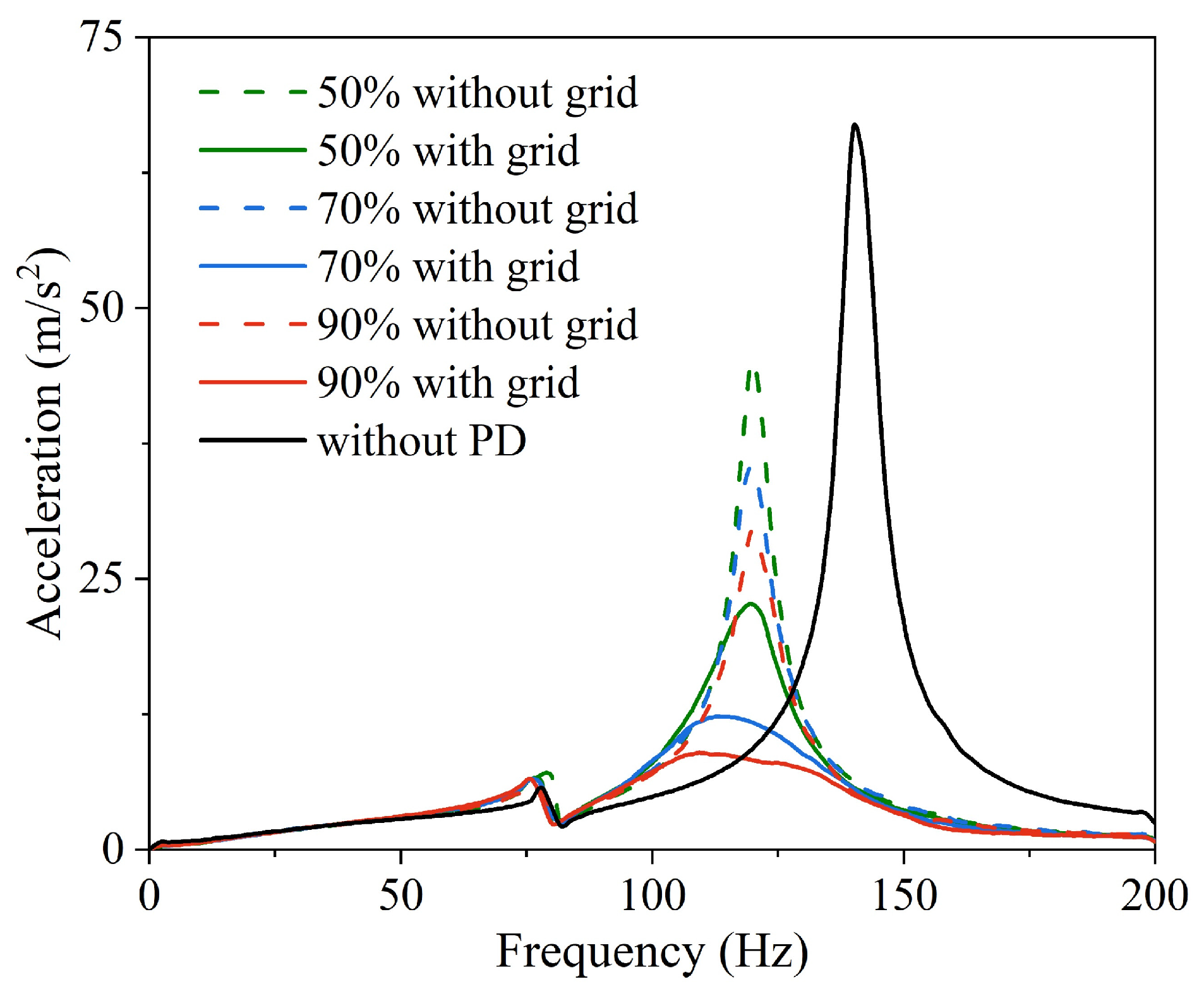
The experiments were filled with 304 stainless steel balls of particle size 2 mm. Particle dampers with and without grid were filled by mass filling ratio of 50%, 70%, and 90%, respectively. The effect of different filling ratios on vibration suppression of the cantilever beam is shown in Figure 3. From the spectrum, it can be seen that the resonance peak exists at 142 Hz with the amplitude reaching 66.5 m/s2 for the empty beam without additional particle dampers. After the particle dampers without grid are attached in the middle of the cantilever beam, the resonance peak is shifted to 120 Hz. However, the resonant frequency decreases with increasing filling ratio after attaching obstacle grid particle dampers to the cantilever beam. The masses of filled particles at different filling ratios are shown in Table 1. As the filling ratio increases and the additional mass increases, the resonant frequency should decrease. The effective mass of the particle dampers without grid is lower than the actual mass of the particles due to the particle motion [41,42]. At 50% fill ratio, the resonance peak amplitude of the conventional particle damper is attenuated by 31.9% compared to the empty beam, while the obstacle grid particle damper further reduces the resonance peak amplitude and attenuates it by 50% compared to the conventional particle damper. At 70% filling ratio, the resonance peak amplitude of the conventional particle damper is attenuated by 46.6% compared to the empty beam, while the obstacle grid particle damper attenuates the resonance peak amplitude by 65.5% compared to the conventional particle damper. At 90% fill ratio, the resonance peak amplitude of the conventional particle damper decays by 55.5% compared to the empty beam, while the obstacle grid particle damper decays by 69.8% compared to the conventional particle damper amplitude.
The resonance peak amplitudes of the cantilever beam with and without the obstacle grid particle dampers at different filling ratios are shown in Figure 4. The damping effect of the particle dampers is gradually enhanced with the increase of filling ratio. It can be seen in Figure 4 that the relationship between the damping effect of the conventional particle damper and the filling ratio is linear, while the resonance peak amplitude of the cantilever beam with the obstacle grid particle damper decays exponentially with the increase of the filling ratio. Compared with the traditional particle dampers, the damping effect of the obstacle grid particle dampers is more significant as the filling ratio increases. The vibration acceleration responses at different filling rates are shown in Table 2.

3.2. Effect of Particle Size on Vibration Characteristics of Cantilever Beam

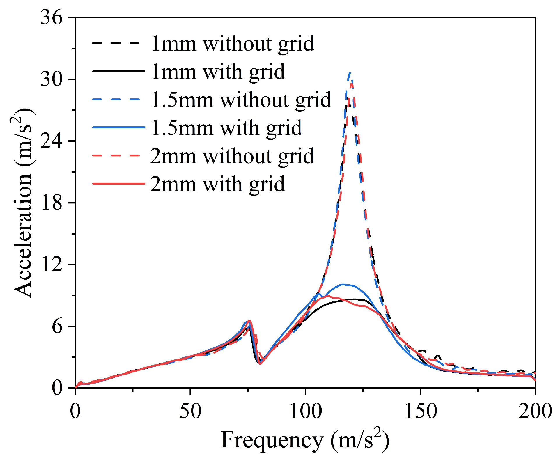
According to the particle damper cavity and obstacle grid size, stainless steel balls with three particle diameters of 1 mm, 1.5 mm, and 2 mm are selected for filling in this paper, as shown in Figure 5. Research particle size on the effect of damping energy consumption of particle dampers with and without obstacle grid.
The damping effect of the cantilever beam with different particle size dampers is shown in Figure 6. From Figure 6, it can be seen that the three particle sizes have the same effect on the energy dissipation with and without the grid particle dampers. The damping effect is best when filled with 1 mm particle size, followed by 2 mm particle size, and 1.5 mm particle size is less effective. The above three particle sizes are 30.7 m/s2, 29.6 m/s2, and 28 m/s2 for conventional particle dampers, and 10 m/s2, 8.9 m/s2, and 8.6 m/s2 for obstacle grid particle dampers. The difference in vibration damping effect between the three particle sizes is not significant, and for cost consideration, the particle size of 2 mm is used In practical applications. The vibration acceleration response at different particle sizes are shown in Table 3.

3.3. Effect of Particle Material on Vibration Characteristics of Cantilever Beam

In this paper, the effect of particle material on the vibration of the cantilever beam is studied by particles of different materials with a particle size of 2 mm. Five materials of particles, aluminum (2.7 g/cm3), zirconia (5.85 g/cm3), stainless steel (7.9 g/cm3), brass (8.5 g/cm3), and lead (11.3437 g/cm3), were selected according to their density, as shown in Figure 7.
The vibration damping effect of particle dampers with different particle materials is shown in Figure 8. Among the five materials, the damping effect of aluminum balls is the worst, on the one hand, the lower density of aluminum leads to the lower kinetic energy of particles, on the other hand, the lower recovery coefficient between aluminum balls affects the collision motion of particles, followed by zirconia particles. In the traditional particle, dampers filled with stainless steel particles damping effect is more significant. The damping effect of copper and lead balls is between zirconia and stainless steel, and the damping effect of copper balls is slightly better than that of lead balls. In the obstacle grid particle dampers, the resonance peak amplitudes of stainless steel, Cu and Pb are 8.71 m/s2, 8.95 m/s2, and 8.89 m/s2, respectively, and the damping effect of the three is not much different. Comprehensive consideration, in practice, should use stainless steel or iron as the filler particles material is more reasonable. The vibration acceleration response under different particle materials are shown in Table 4.

3.4. Effect of Excitation Amplitude on Vibration Characteristics of Cantilever Beam

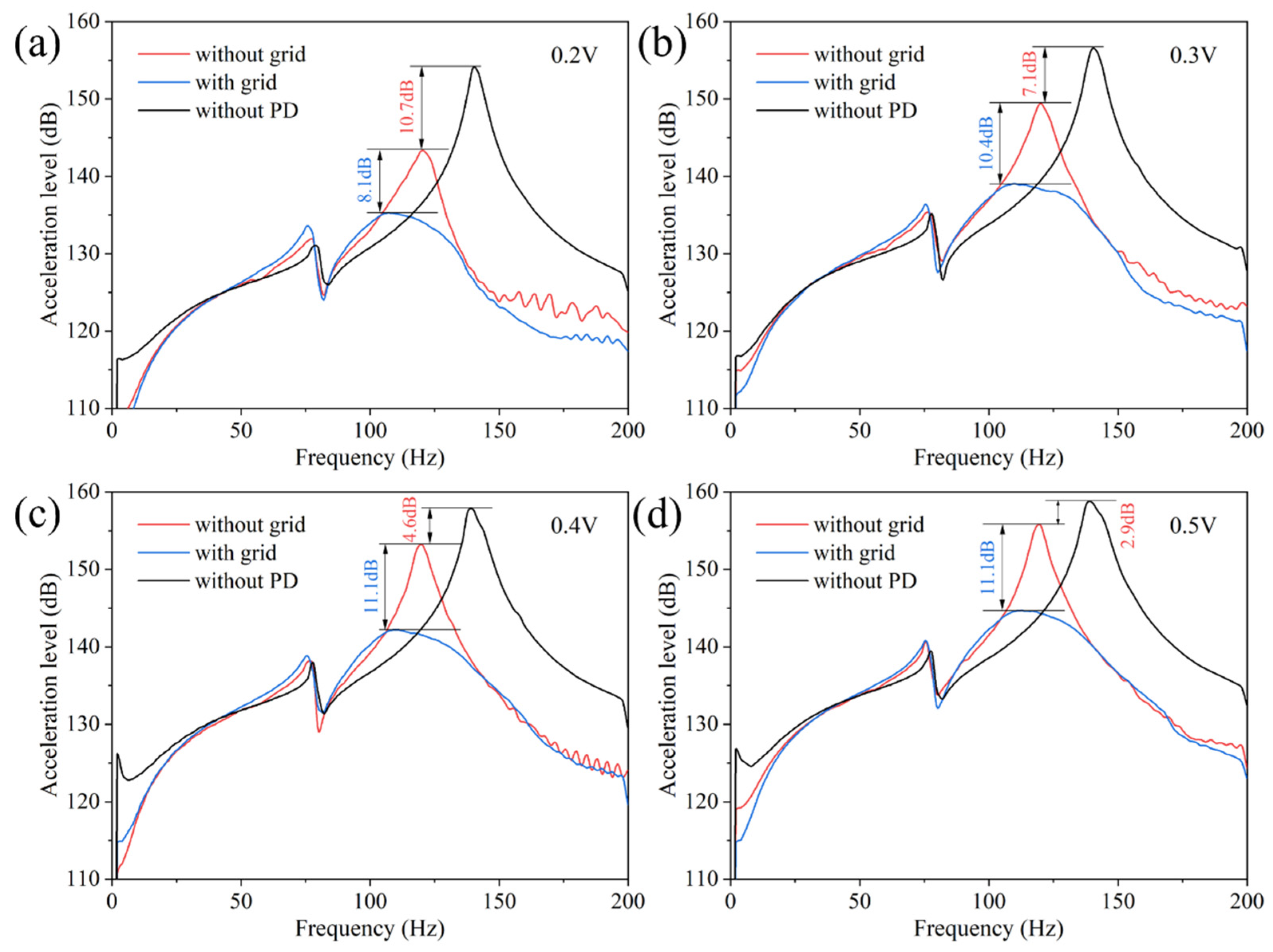
The damping effect of particle damping is greatly influenced by the excitation amplitude. In this paper, the excitation amplitude is adjusted by setting 0.2 V~0.5 V by the signal generator for different excitation amplitudes of the shaker. The vibration response of the cantilever beam with and without the obstacle grid particle dampers under different excitation amplitudes is shown in Figure 9. It can be seen from Figure 9a that the vibration damping effect of the conventional particle dampers on the cantilever beam structure reaches 10.7 dB, and the vibration response of the conventional particle dampers is attenuated by 8.1 dB through the built-in obstacle grid. It is worth noting that the damping effect of the obstacle grid particle dampers gradually increases with the increase of the excitation amplitude compared with the conventional particle dampers. In Figure 9c,d, the vibration response of the obstacle grid particle damper is attenuated by 11.1 dB compared with the conventional particle damper.

4. Analysis and Discussion

4.1. Damping Energy Dissipation Characteristics of the Particle Dampers with Obstacle Grid

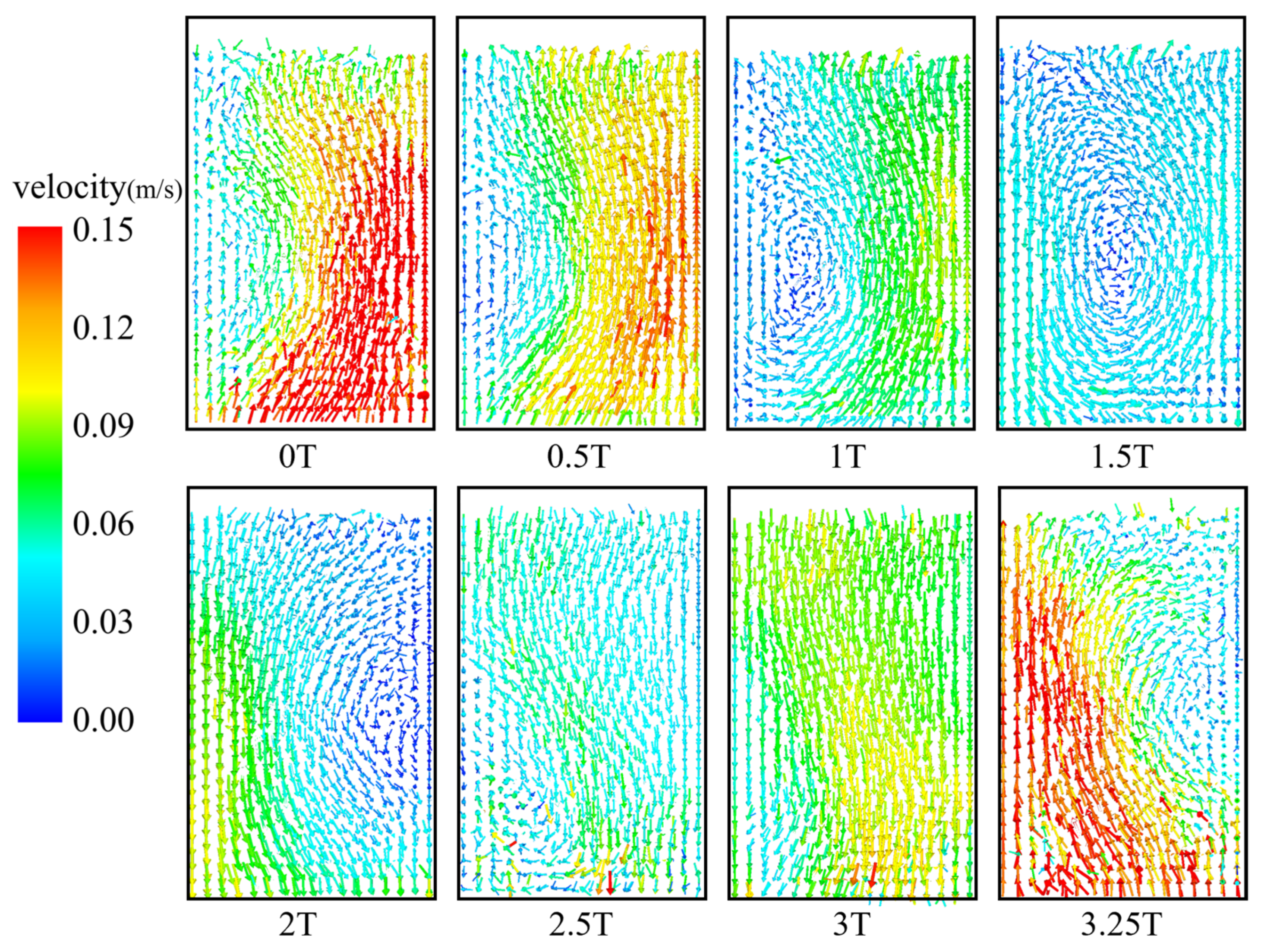
In this paper, the discrete element software (EDEM) is used to simulate and model the particle dampers with and without the obstacle grid, respectively, and the particle dampers and particle size dimensions are consistent with the experimental model. First, a particle generation filling simulation is performed, where the number of particles is derived by dividing the total mass of particles obtained from the experimental filling by the mass of individual particles. The vertical sinusoidal vibration simulation of the particle dampers was simulated by EDEM software, and the particle dampers were all filled with 90% of 2 mm particles in the simulation. The discrete element simulation time step is 2.14773 × −7 s (20% of the Rayleigh time step) and the storage time step is 0.001 s. The physical parameters used in the discrete element simulation are shown in Table 5.The discrete element contact parameters in Table 5 are calibrated by static experiments in combination with the parameter calibration module EDEMCal in the EDEM2021 software [43]. The resonant peak frequency (120 Hz) and the acceleration at the additional position of the particle dampers (10.5 g) were used as the excitation conditions according to the experimental cantilever beam after the particle dampers were attached. The particle motion vector in the particle damper without grid is shown in Figure 10. Due to the rheological phenomenon of particles, the particle motion in the particle damper without grid produces vortex motion after colliding with the bottom surface and moving upward, and experiences 3.25 excitation vibration cycles to end the vortex motion. The low kinetic energy of the particles in the 3.25 cycles of vortex motion is mainly due to the fact that there is no effective vibration energy transfer between the particles in the vortex motion state and the damper wall.
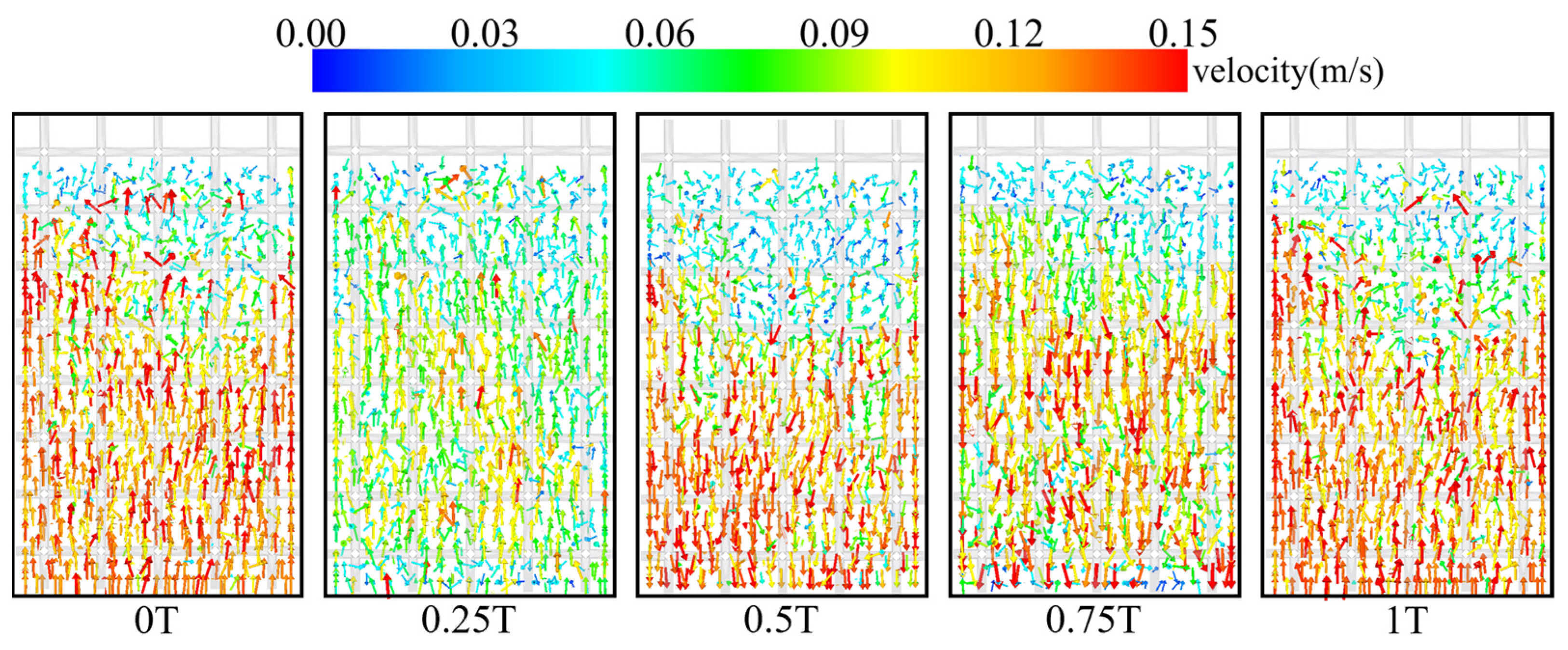
The vector diagram of particle motion in the particle damper with obstacle grid during one excitation period is shown in Figure 11. By embedding the obstacle grid in the particle damper cavity, the particle rheology is prevented. It can be seen from the figure that the particle motion period in the particle damper with grid is consistent with the excitation period. The kinetic energy of the particles is significantly larger than that of the particles without the grid. In addition, the kinetic energy of the particles in the particle damper with grid is also larger than that of the particles without grid. In addition to the kinetic energy of the particles in the particle damper with grid colliding with the wall, it can be seen from the two moments of 0.5 T and 0.75 T that when the particle damper with grid moves downward, the collision of the particles with grid causes the particles to have larger kinetic energy.
The kinetic energy and energy dissipation of the particle dampers with and without the grid are obtained from the discrete element simulation and analyzed for comparison, as shown in Figure 12. Figure 12a shows the time domain variation of the kinetic energy of the particle dampers. The kinetic energy of the particle dampers without a grid has widely spaced pulse spikes, and the kinetic energy is almost zero at the peaks and valleys. The kinetic energy in the particle dampers with grid is dense and fluctuates above and below the energy amplitude of 0.008 J. Compared with the particle dampers without grid, the kinetic energy with grid is higher at any moment. Figure 12b shows the kinetic energy spectrum of the particle damper with and without grid, from which it can be seen that the kinetic energy of the particle damper without grid is composed of 40 Hz additional band and 120 Hz and its multiples, in which the amplitude is higher at 40 Hz and lower at the excitation frequency of 120 Hz and its multiples, which means that the particle motion frequency in the particle damper without grid is much lower than the excitation frequency. The kinetic energy in the particle dampers with a grid is composed of 120 Hz and its multiples in the spectrum, with a higher amplitude at 240 Hz. The double frequency characteristics correspond to the particle collision characteristics twice in one excitation period in Figure 11.
The loss energy with and without grid particle dampers is shown in Figure 12c. Similar to the particle kinetic energy variation, the particle dampers without grid show intermittent pulse energy dissipation. There are many cycles in which the energy loss tends to zero. In contrast, the energy loss at any moment is lower than that of the particle dampers without grid, but the overall energy loss is 2.48 times higher than that of the particle dampers without grid. From the particle energy dissipation spectrum in Figure 12d, it can be seen that the energy dissipation without grid is composed of the frequency band from 40 Hz to 80 Hz and 120 Hz and its multiples. The particle dampers with grid are composed of excitation frequency 120 Hz and its multiples, and the highest amplitude is at the dipole frequency 240 Hz.
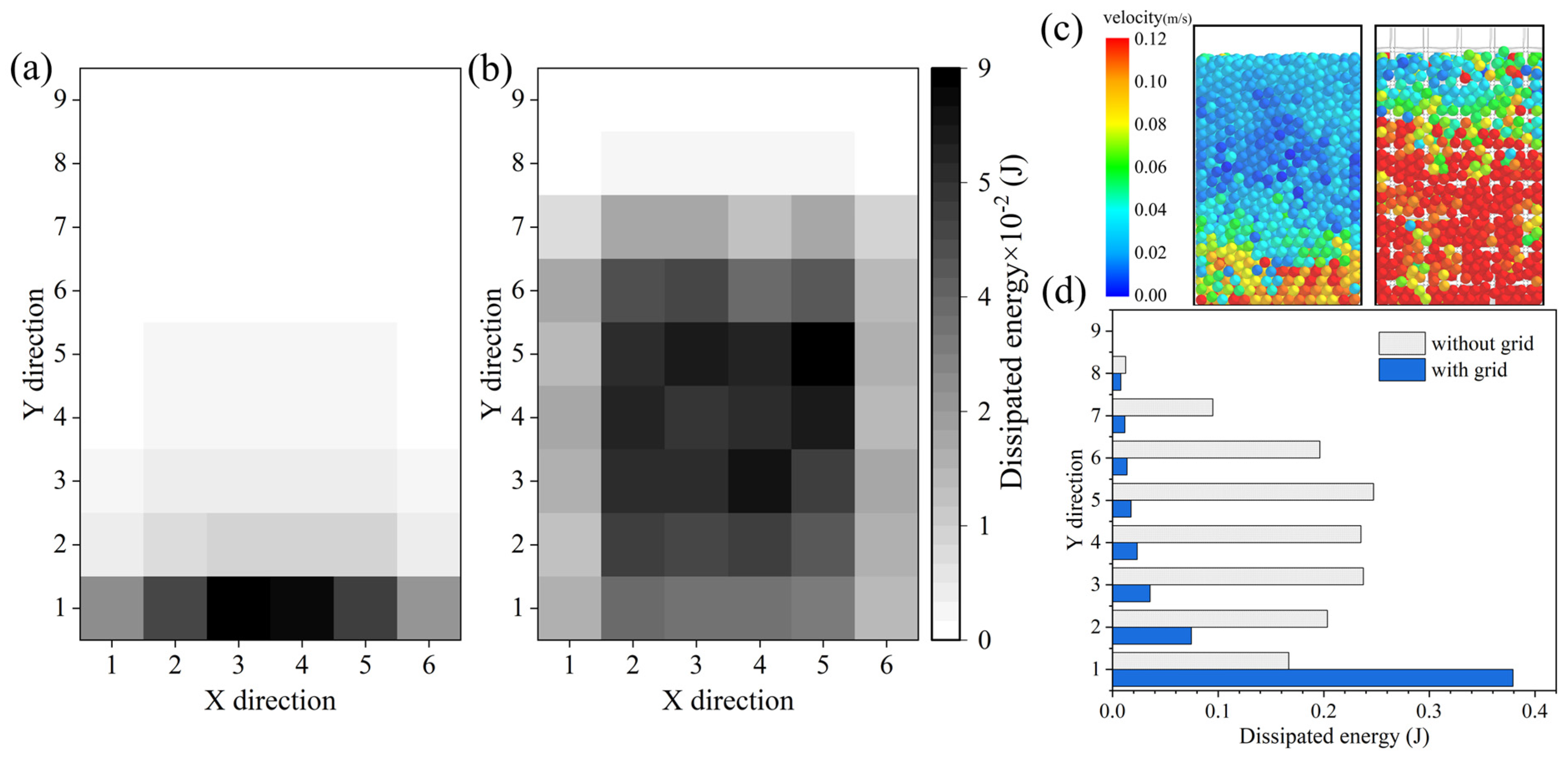
According to the obstacle grid cell division area, the spatial energy dissipation distribution of particle dampers with and without grid is shown in Figure 13a, the energy dissipation of particle dampers without grid is mainly distributed in the lowest layer, and the energy dissipation decreases with the rise of the number of layers, and the trend of high in the middle and low on the sides in the horizontal. The energy dissipation of the particle dampers with a grid is mainly distributed in layers 1–7, with the largest energy dissipation in layer 5. Compared with particle dampers without grid, the energy dissipation in the lowest layer is lower than that in particle dampers without grid, but the energy loss in layers 2–7 is much higher than that in particle dampers without grid.
In summary, the obstacle grid prevents the particles from undergoing fluidization phenomenon and increases the area of energy transfer between the external vibration energy and the particles. It makes the particles, which originally have almost no contribution to energy dissipation, produce violent motion and participate in the energy dissipation process, which effectively improves the damping performance of the particle damper.

4.2. Effect of Excitation Amplitude on Particle Damping Energy Dissipation

The particle damping is greatly influenced by the excitation conditions, and the particle motion shows rich motion patterns under different excitation conditions. The particle damping shows solid-like, local fluidization, global fluidization, trampoline, convection, Leyland effect flow, and buoyant convection motion states one by one as the excitation amplitude increases. Our team carried out the experiments with and without grid particle damping loss factor in the early stage, and the relevant experimental principles and settings were referred to in the literature [23], and the accuracy of the discrete element simulation model was verified by the loss factor experiments. The effect of excitation amplitude on the loss factor of the particle dampers is shown in Figure 14. The loss factor of the particle damper without grid is higher than that of the gridded particle damper in the excitation intensity Γ = 0.5–2.5 interval, and there is a sharp decrease in the loss factor of the particle damper without grid as the excitation intensity increases, while the gridded particle damper has a slow decreasing trend in the interval Γ > 2.5, so the loss factor of the gridded particle damper is improved by 0.11 over the particle damper without grid in this interval. Therefore, the obstacle grid can solve the difficulty that the damping effect of the conventional particle dampers fails at higher excitation amplitude values. The obstacle grid particle dampers can be practically applied in strong vibration conditions, such as stern vibration, strong shock of space capsule arrow separation, strong vibration in aircraft acceleration and dive state, etc.

5. Conclusions

In this paper, the obstacle grid particle dampers are attached to the cantilever beam structure, and the superiority of the particle dampers with obstacle grid is fully demonstrated by comparing the damping effect with the conventional particle dampers. The discrete element method was used to simulate the particle dampers with and without the obstacle grid separately. Energy dissipation characteristics of the obstacle grid particle dampers were analyzed. It can be concluded as follows.
(1)
As the filling ratio increases, the effect of the obstacle grid particle damper on the cantilever beam vibration suppression becomes more and more obvious. At the filling ratio of 90%, the acceleration amplitude of the cantilever beam with grid particle dampers decreased by 69.8% compared to the cantilever beam without grid particle dampers with additional grid particle dampers. The best damping effect was achieved when the particle dampers were filled with 1 mm particle size, followed by 2 mm and 1.5 mm particles.
(2)
The particle material has a large impact on the damping performance of the particle damper. Among the five materials, aluminum balls have the worst damping effect, followed by zirconium oxide particles. In the traditional particle dampers filled with stainless steel particles, damping effect is more significant. The damping effect of copper and lead balls is between zirconia and stainless steel, and the damping effect of copper balls is slightly better than that of lead balls. The difference between the damping effect of stainless steel, Cu, and Pb in the particle dampers with obstacle grid is small.
(3)
With the increase of excitation amplitude, the damping effect of traditional particle damper is 10.7 dB, 7.1 dB, 4.6 dB, and 2.9 dB, respectively, while the damping effect of obstacle grid particle damper decreases 8.1 dB, 10.4 dB, 11.1 dB, and 11.1 dB, respectively. The particle damper with grid still has good damping characteristics.
(4)
Conventional particle dampers reduce the level of vibration energy transfer and dissipation due to fluidization of particles. The energy transfer area of the particle dampers is increased, and the energy dissipation of the particle dampers is enhanced by embedding the obstacle grid energy to hinder the generation of particle fluidization.

Author Contributions

Conceptualization, J.Z. and H.Z.; methodology, J.Z.; software, Y.H. and J.J.; validation, J.Z., Y.H. and H.Z.; formal analysis, J.Z.; investigation, H.Z.; resources, J.Z.; data curation, J.Z. and J.J.; writing—original draft preparation, J.Z.; writing—review and editing, J.Z.; visualization, Y.H.; supervision, H.Z.; project administration, J.Z.; funding acquisition, J.Z. All authors have read and agreed to the published version of the manuscript.

Funding

This research received no external funding.

Data Availability Statement

The data presented in this study are available upon request from the corresponding author.

Conflicts of Interest

The authors declare no conflict of interest.

References

  1. Veeramuthuvel, P.; Shankar, K.; Sairajan, K.K. Application of particle damper on electronic packages for spacecraft. Acta Astronaut. 2016, 127, 260–270. [Google Scholar] [CrossRef]
  2. Jin, G.; Zhao, Z. Design of a particle damper and experimental study on vibration damping of the pipeline. Adv. Mech. Eng. 2021, 13, 16878140211044923. [Google Scholar] [CrossRef]
  3. Lei, X.; Wu, C.; Wu, H. A novel composite vibration control method using double-decked floating raft isolation system and particle damper. J. Vib. Control 2018, 24, 4407–4418. [Google Scholar] [CrossRef]
  4. Xiao, W.; Xu, Z.; Bian, H.; Li, Z. Lightweight heavy-duty CNC horizontal lathe based on particle damping materials. Mech. Syst. Signal Process. 2021, 147, 107127. [Google Scholar] [CrossRef]
  5. Wang, M.; Xu, H.; He, D.; Wang, T.; Zhang, J. Design of a damped vibration absorber to control the resonant vibration of roll. Mech. Syst. Signal Process. 2022, 178, 109262. [Google Scholar] [CrossRef]
  6. Xiao, W.; Lu, D.; Song, L.; Guo, H.; Yang, Z. Influence of particle damping on ride comfort of mining dump truck. Mech. Syst. Signal Process. 2020, 136, 106509. [Google Scholar] [CrossRef]
  7. Jin, J.; Kim, H.; Koh, H.I.; Park, J. Railway noise reduction by periodic tuned particle impact damper with bounce and pitch-coupled vibration modes. Compos. Struct. 2022, 284, 115230. [Google Scholar] [CrossRef]
  8. Zhao, C.; Shi, D.; Zheng, J.; Niu, L.; Wang, P. New floating slab track isolator for vibration reduction using particle damping vibration absorption and bandgap vibration resistance. Constr. Build. Mater. 2022, 336, 127561. [Google Scholar] [CrossRef]
  9. Prasad, B.B.; Duvigneau, F.; Juhre, D.; Woschkeet, E. Application of Particle Dampers on a Scaled Wind Turbine Generator to Improve Low-Frequency Vibro-Acoustic Behavior. Appl. Sci. 2022, 12, 671. [Google Scholar] [CrossRef]
  10. Lu, Z.; Liao, Y.; Huang, Z. Stochastic response control of particle dampers under random seismic excitation. J. Sound Vib. 2020, 481, 115439. [Google Scholar] [CrossRef]
  11. Gagnon, L.; Morandini, M.; Ghiringhelli, G.L. A review of particle damping modeling and testing. J. Sound Vib. 2019, 459, 114865. [Google Scholar] [CrossRef]
  12. Mao, K.; Wang, M.Y.; Xu, Z.; Chen, T. Simulation and characterization of particle damping in transient vibrations. J. Vib. Acoust. 2004, 126, 202–211. [Google Scholar] [CrossRef]
  13. Mao, K.; Wang, M.Y.; Xu, Z.; Chen, T. DEM simulation of particle damping. Powder Technol. 2004, 142, 154–165. [Google Scholar] [CrossRef]
  14. Wong, C.X.; Daniel, M.C.; Rongong, J.A. Energy dissipation prediction of particle dampers. J. Sound Vib. 2009, 319, 91–118. [Google Scholar] [CrossRef] [Green Version]
  15. Biondani, F.; Morandini, M.; Ghiringhelli, G.L.; Terraneo, M.; Cordisco, P. Efficient Discrete Element Modeling of Particle Dampers. Processes 2022, 10, 1247. [Google Scholar] [CrossRef]
  16. Wu, C.J.; Liao, W.H.; Wang, M.Y. Modeling of granular particle damping using multiphase flow theory of gas-particle. J. Vib. Acoust. 2004, 126, 196–201. [Google Scholar] [CrossRef]
  17. Xia, Z.; Mao, K.; Wei, S.; Wang, X.; Fang, Y.; Yang, S. Application of genetic algorithm-support vector regression model to predict damping of cantilever beam with particle damper. J. Low Freq. Noise Vib. Act. Control 2017, 36, 138–147. [Google Scholar] [CrossRef] [Green Version]
  18. Ye, X.; Ni, Y.Q.; Sajjadi, M.; Wang, Y.; Lin, C. Physics-guided, data-refined modeling of granular material-filled particle dampers by deep transfer learning. Mech. Syst. Signal Process. 2022, 180, 109437. [Google Scholar] [CrossRef]
  19. Bai, X.M.; Keer, L.M.; Wang, Q.J.; Snurr, R.Q. Investigation of particle damping mechanism via particle dynamics simulations. Granul. Matter 2009, 11, 417–429. [Google Scholar] [CrossRef]
  20. Masmoudi, M.; Job, S.; Abbes, M.S.; Tawfiq, I.; Haddar, M. Experimental and numerical investigations of dissipation mechanisms in particle dampers. Granul. Matter 2016, 18, 71. [Google Scholar] [CrossRef]
  21. Pourtavakoli, H.; Parteli, E., Jr.; Pöschel, T. Granular dampers: Does particle shape matter? New J. Phys. 2016, 18, 073049. [Google Scholar] [CrossRef] [Green Version]
  22. Koch, S.; Duvigneau, F.; Orszulik, R.; Gabbert, U.; Woschke, E. Partial filling of a honeycomb structure by granular materials for vibration and noise reduction. J. Sound Vib. 2017, 393, 30–40. [Google Scholar] [CrossRef]
  23. Romdhane, M.B.; Bouhaddi, N.; Trigui, M.; Foltete, E.; Haddar, M. The loss factor experimental characterisation of the non-obstructive particles damping approach. Mech. Syst. Signal Process. 2013, 38, 585–600. [Google Scholar] [CrossRef]
  24. Meyer, N.; Seifried, R. Numerical and experimental investigations in the damping behavior of particle dampers attached to a vibrating structure. Comput. Struct. 2020, 238, 106281. [Google Scholar] [CrossRef]
  25. Meyer, N.; Seifried, R. Toward a design methodology for particle dampers by analyzing their energy dissipation. Comput. Part. Mech. 2021, 8, 681–699. [Google Scholar] [CrossRef]
  26. Meyer, N.; Schwartz, C.; Morlock, M.; Seifried, R. Systematic design of particle dampers for horizontal vibrations with application to a lightweight manipulator. J. Sound Vib. 2021, 510, 116319. [Google Scholar] [CrossRef]
  27. Zhang, K.; Chen, T.; Wang, X.; Fang, J. Rheology behavior and optimal damping effect of granular particles in a non-obstructive particle damper. J. Sound Vib. 2016, 364, 30–43. [Google Scholar] [CrossRef]
  28. Yin, Z.; Su, F.; Zhang, H. Investigation of the energy dissipation of different rheology behaviors in a non-obstructive particle damper. Powder Technol. 2017, 321, 270–275. [Google Scholar] [CrossRef]
  29. Meyer, N.; Seifried, R. Energy dissipation in horizontally driven particle dampers of low acceleration intensities. Nonlinear Dyn. 2022, 108, 3009–3024. [Google Scholar] [CrossRef]
  30. Jadhav, T.A.; Awasare, P.J. Enhancement of particle damping effectiveness using multiple cell enclosure. J. Vib. Control 2016, 22, 1516–1525. [Google Scholar] [CrossRef]
  31. Yao, B.; Chen, Q.; Xiang, H.Y.; Gao, X. Experimental and theoretical investigation on dynamic properties of tuned particle damper. Int. J. Mech. Sci. 2014, 80, 122–130. [Google Scholar] [CrossRef]
  32. Zhang, K.; Xi, Y.; Chen, T.; Ma, Z. Experimental studies of tuned particle damper: Design and characterization. Mech. Syst. Signal Process. 2018, 99, 219–228. [Google Scholar] [CrossRef]
  33. Hamed, Y.S.; el Shehry, A.; Sayed, M. Nonlinear modified positive position feedback control of cantilever beam system carrying an intermediate lumped mass. Alex. Eng. J. 2020, 59, 3847–3862. [Google Scholar] [CrossRef]
  34. Sayed, M.; Mousa, A.A.; Alzaharani, D.Y. Bifurcation analysis of a composite cantilever beam via 1: 3 internal resonance. J. Egypt. Math. Soc. 2020, 28, 1–21. [Google Scholar] [CrossRef]
  35. Sayed, M.; Mousa, A.A.; Mustafa, I. Stability and bifurcation analysis of a buckled beam via active control. Appl. Math. Model. 2020, 82, 649–665. [Google Scholar] [CrossRef]
  36. Arumugam, A.B.; Subramani, M.; Dalakoti, M. Dynamic characteristics of laminated composite CNT reinforced MRE cylindrical sandwich shells using HSDT. Mech. Based Des. Struct. 2021, 1–17. [Google Scholar] [CrossRef]
  37. Shareef, S.S.; Rajeshkumar, S.; Rauf, H.L. A Numerical Study on Forced Vibration Analysis and Optimum Design of Rotating Composite Multiwalled Carbon Nanotubes-Reinforced Smart Sandwich Plate. Int. J. Struct. Stab. Dyn. 2022, 22, 2250009. [Google Scholar] [CrossRef]
  38. Ferreyra, M.V.; Gómez-Paccapelo, J.M.; Suarez, R.; Pugnaloni, L.A. Avoiding chaos in granular dampers. In EPJ Web of Conferences; EDP Sciences: Les Ulis, France, 2021; Volume 249, p. 15003. [Google Scholar]
  39. Yao, B.; Chen, Q. Investigation on zero-gravity behavior of particle dampers. J. Vib. Control 2015, 21, 124–133. [Google Scholar] [CrossRef]
  40. Gnanasambandham, C.; Fleissner, F.; Eberhard, P. Enhancing the dissipative properties of particle dampers using rigid obsta-cle-grids. J. Sound Vib. 2020, 484, 115522. [Google Scholar] [CrossRef]
  41. Liu, W.; Tomlinson, G.R.; Rongong, J.A. The dynamic characterisation of disk geometry particle dampers. J. Sound Vib. 2005, 280, 849–861. [Google Scholar] [CrossRef]
  42. Sánchez, M.; Pugnaloni, L.A. Effective mass overshoot in single degree of freedom mechanical systems with a particle damper. J. Sound Vib. 2011, 330, 5812–5819. [Google Scholar] [CrossRef] [Green Version]
  43. Xia, R.; Li, B.; Wang, X.; Li, T.; Yang, Z. Measurement and calibration of the discrete element parameters of wet bulk coal. Measurement 2019, 142, 84–95. [Google Scholar] [CrossRef]
Figure 1. Particle damper model.
Machines 10 00989 g001
Figure 2. Schematic diagram (left) and picture(right) of the testbed.
Machines 10 00989 g002
Figure 3. Vibration response of cantilever beam with and without obstacle grid particle dampers.
Machines 10 00989 g003
Figure 4. Vibration amplitude of cantilever beam with and without obstacle grid particle dampers at different filling ratios.
Machines 10 00989 g004
Figure 5. Different particle size samples.
Machines 10 00989 g005
Figure 6. Vibration response of cantilever beam with and without obstacle grid particle dampers at different particle sizes.
Machines 10 00989 g006
Figure 7. Particle samples of different materials.
Machines 10 00989 g007
Figure 8. Vibration response of cantilever beam with and without obstacle grid particle dampers with different particle materials.
Machines 10 00989 g008
Figure 9. Vibration response of cantilever beam with and without obstacle grid particle dampers under different excitation amplitudes, excitation voltage (a) 0.2 V, (b) 0.3 V, (c) 0.4 V, (d) 0.5 V.
Machines 10 00989 g009
Figure 10. Particle motion in a particle damper without grid.
Machines 10 00989 g010
Figure 11. Particle motion in the obstacle grid particle damper.
Machines 10 00989 g011
Figure 12. (a) Time domain diagram of particle damping kinetic energy; (b) spectrum of particle damping kinetic energy; (c) time domain diagram of particle damping dissipation energy; (d) spectrum of particle damping dissipation energy.
Machines 10 00989 g012
Figure 13. Energy dissipation distribution within the grid cell region of the particle damper, (a) without grid; (b) with grid; (c) velocity cloud of the particle damper with and without grid; (d) energy dissipation distribution in the Y-direction of the particle damper with and without grid.
Machines 10 00989 g013
Figure 14. Effect of excitation amplitude on damping performance of particle dampers.
Machines 10 00989 g014
Table 1. Different filling ratio particles and model masses in the experiment.
MassShell (g)Grid (g)Filling Ratio 50% (g)Filling Ratio 70% (g)Filling Ratio 90% (g)
Without grid122/105147189
With grid1223.385119153
Table 2. Vibration acceleration response at different filling ratios.
Filling Ratios50%60%70%80%90%Without PD
Without grid45.4 m/s238.6 m/s235.5 m/s232.5 m/s229.6 m/s266.5 m/s2
With grid22.7 m/s216.2 m/s212.2 m/s211.6 m/s28.9 m/s2
Table 3. Vibration acceleration response at different particle sizes.
Particle Sizes1 mm1.5 mm2 mm
Without grid27.9 m/s230.7 m/s229.6 m/s2
With grid8.6 m/s210 m/s28.9 m/s2
Table 4. Vibration acceleration response under different particle materials.
MaterialsAlZrOSteelCuPb
Without grid47.4 m/s236.1 m/s229.6 m/s232.5 m/s233.2 m/s2
With grid22.5 m/s211.4 m/s28.9 m/s29 m/s28.9 m/s2
Table 5. Physical properties and parameters used in DEM simulation.
ComponentsDensity
(kg/m3)
Poisson’s
Ratio
Young’s Modulus
(Pa)
Coefficient of RestitutionCoefficient of Static FrictionCoefficient of Rolling Friction
Particle79300.32.06 × 10110.740.20.01
Shell11900.323.3 × 1090.30.1540.01
Grid11200.232.46 × 1090.70.30.01
Publisher’s Note: MDPI stays neutral with regard to jurisdictional claims in published maps and institutional affiliations.