1. Introduction
The excavator is an important form of construction machinery with multiple actuators, and it mainly suffers from low energy efficiency and poor maneuverability. Driven by the fast-growing economy and energy and environmental issues, there is increasingly high demand for energy saving and maneuverability of excavators [
1,
2,
3,
4]. The load-independent flow distribution (LUDV) system [
5,
6] is widely used in excavators due to its excellent flow distribution characteristics. However, the LUDV system uses a pressure margin to adjust the pump displacement [
7], and the load pressure always fluctuates sharply, which makes the pump control signal change steeply, and the system oscillation tendency is particularly obvious, which seriously affects the operator’s manipulation experience. In addition, the flow supply of the joystick/main valve often exceeds the flow demand of actuator, which causes excessive overflow [
8,
9,
10] and reduces the fuel economy. In particular, the turntable and boom of the excavator have great inertia, and their actions occupy a larger proportion in the entire excavator working cycle. Moreover, the moments of low efficiency and poor dynamics mostly occur during the actuator acceleration process. Therefore, it is of great significance to carry out research on the acceleration performance optimization of the large inertia hydraulic actuator.
At present, the related studies can be divided into two types; that is, control principle improvement and control algorithm optimization. In terms of the control principle improvement, it mainly includes the electro-hydraulic load sensing (ELS) system and independent metering control (IMC) system. The ELS system [
11,
12,
13] replaces the hydro-mechanical pump with the electro-hydraulic pump, and adjusts the pump displacement through the electronic-pressure margin or flow feedforward, so as to improve the system responsiveness and dynamic stability. The IMC system [
14,
15,
16] independently adjusts the valves (hydraulic resistance) at the inlet and outlet of actuator, so as to reduce the valve pressure loss and improve the system-damping characteristics. Control algorithm optimization mainly includes the pump control algorithm and the valve control algorithm. Hu et al. integrated an electroproportional pressure-reducing valve on the mechano-hydraulic load sensing (LS) valve of the LS pump to dynamically adjust the system pressure margin, thereby improving the energy efficiency and dynamic response [
17]. Axin et al. proposed a hybrid pressure-flow control algorithm for the electric pump, which calculates the outputs of the ELS controller and the EFM (electrohydraulic flow matching) controller with different weighting factors to control the pump, and the system dynamic performances are improved [
18,
19]. Min et al. proposed a multi-objective optimization-active damping method for the valve-controlled hydraulic system to determine the control parameters of the high-pass pressure filter, so as to reduce the dynamic impact caused by force disturbance [
20]. Ding et al. proposed a control algorithm combining a meter-out valve control and a pump flow/pressure hybrid control for an IMC system, which minimizes the pressure loss by maximizing the meter-out valve opening [
21]. Rath et al. proposed a band-reject filter input shaping method, and applied it to the valves of IMC system, which can suppress the resonant frequency caused by the load inertia [
22].
All in all, there are only two kinds of optimal control methods that can improve the performance of hydraulic systems/actuators, namely closed-loop-feedback control and open-loop-input shaping control [
23,
24]. The existing feedback control methods can improve the energy efficiency and dynamic stability of the system. However, the existing input shaping control methods are often only used to eliminate residual oscillations related to the natural frequency and damping ratio of the system, and are rarely used to optimize the energy efficiency.
In practice, the excavator is a type of construction machinery that adopts a human-in-the-loop operation mode, and experienced operators can often obtain satisfactory system performance by appropriately manipulating joysticks. Nevertheless, there are few studies on the open-loop control algorithm designed for human–joystick input and actuator-load characteristics. In addition, the main valve flow always changes in real time with the operator’s command (quick push–pull input); however, if the actuator load is very inert, it will be difficult for the main valve flow to dynamically match the actuator speed; at the same time, the actuator drive chamber has a large volume and the hydraulic oil is compressible [
25], which makes the system prone to flow-pressure oscillations. Therefore, in order to improve the acceleration performance of large inertia hydraulic actuator, this paper explores the effect of the main valve control signal slope-flow growth rate on the actuator pressure-flow characteristics, designs a main valve input shaping control strategy, and carries out tests and simulations based on a 6-ton LUDV excavator to verify the beneficial effect of the proposed control strategy.
2. System Principle
2.1. LUDV System
The application of an LUDV hydraulic system greatly improves the working performance of an excavator. However, the disorderly human–joystick input, system control characteristics, and actuator-load characteristics do not adapt to each other, which means that the LUDV system suffers from low energy efficiency and oscillation tendency.
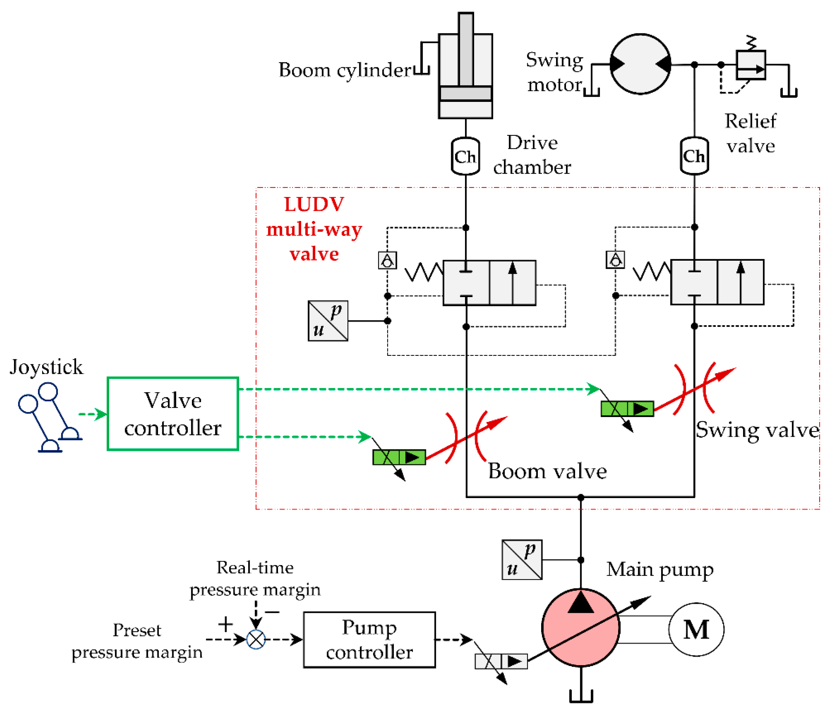
As shown in
Figure 1, the LUDV system mainly includes the joystick, electronic control pump, pump controller, swing/boom (main) valve, valve controller, pressure sensors, drive chambers, swing motor, and boom cylinder. The pump controller adjusts the pump displacement by controlling the pressure margin, which is the pressure difference between the main pump and the highest load. The valve controller adjusts the control pressure/opening of the electro-hydraulic main valve according to the joystick command signal. Importantly, the key factor in this study was to use an open-loop control method to adjust the joystick command signal, so that main valve power supply could be stably and fully absorbed by the actuator load.
2.2. Model Analysis
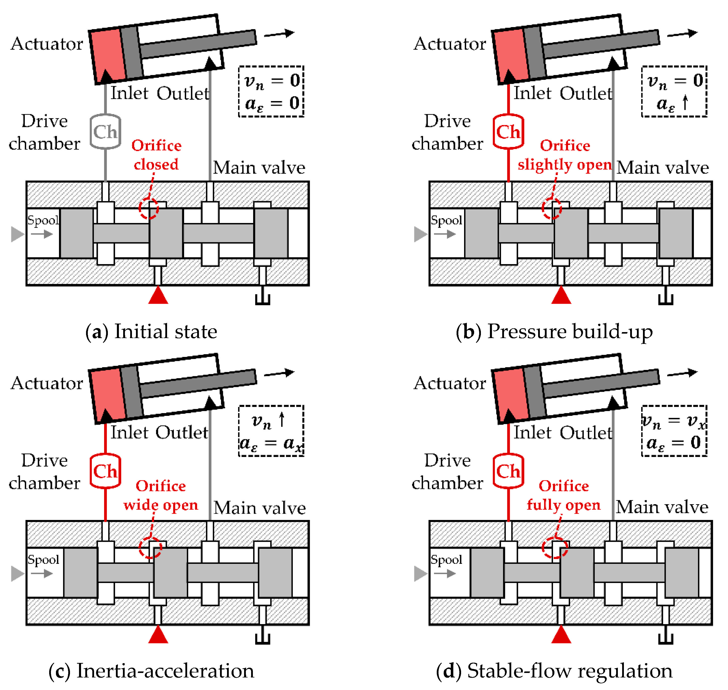
As shown in
Figure 2, it is a simple hydraulic cylinder/motor model, a name which mainly describes the interaction between the main valve flow, the drive chamber and the actuator load.
According to
Figure 2, the force balance equation of boom cylinder/swing motor can be expressed as
where
is the driving pressure of the cylinder/motor,
is the cylinder piston area/motor displacement,
is the load mass/inertia,
is the velocity/angular velocity of the cylinder/motor,
is the friction coefficient, and
is the external force/torque.
The flow continuity equation of the cylinder/motor can be expressed as
where
is the volume of the cylinder/motor working chamber,
is the bulk modulus of hydraulic oil, and
is the inlet flow of the boom cylinder or swing motor. Then,
Combining (1), (2), and (3), the following expression can be obtained.
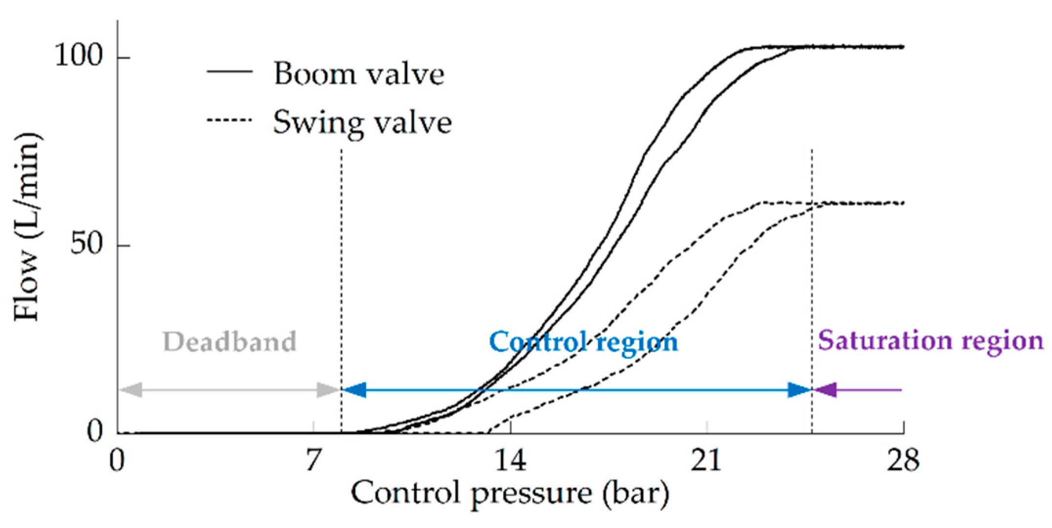
According to the flow control characteristic curves of the boom/swing valve, as shown in
Figure 3, the valve flow is approximately proportional to its control pressure within the control region.
Hence, the main valve flow
can be expressed as
where
is a constant,
is the main valve control pressure,
is the control pressure that makes the overlap of main valve equal to zero.
The joystick command signal can be roughly regarded as a ramp signal with a specific slope. If
is a ramp signal, and its slope is
. Hence, the main valve flow can be expressed as
where
is the time,
is a certain moment.
In (6),
can be expressed as
Considering that the main valve flow all flows into the actuator, and then
Therefore, (4) can be rewritten as
The solution of (9) is
where
and
are coefficients, and
is the natural frequency of the actuator system.
According to (10), when is relatively constant and is big enough, the driving pressure of the LUDV actuator is mainly affected by the main valve control signal slope . In addition, the system response, stability, and flow/pressure overmatching are usually related to the dynamics of the driving pressure. Thus, the LUDV actuator acceleration performance can be improved by adjusting the signal slope .
In practice, the actuator driving pressure characteristic curves of a 6-ton LUDV excavator are shown in
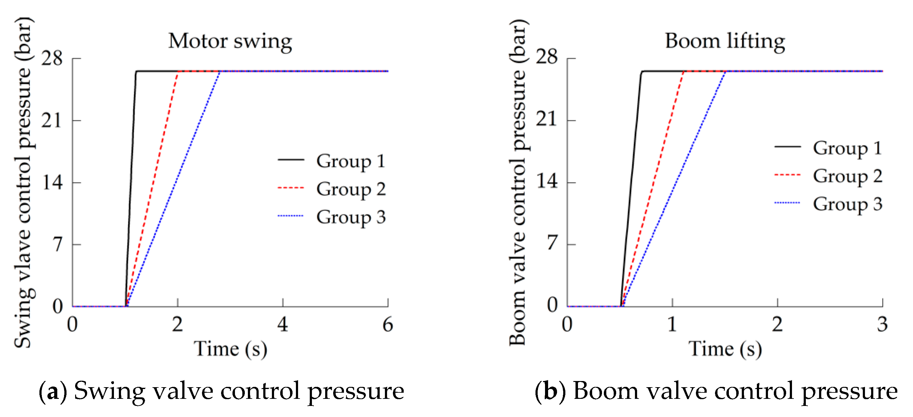
Figure 4, and it can be seen that the small-slope main valve control signal can make the actuator obtain better pressure stability. However, operators often choose the large-slope main valve control signal to ensure the working efficiency of excavator. Thus, this paper designed a main valve input shaping control strategy to appropriately adjust the signal slope-flow growth rate of main valve, thereby improving the dynamic stability and energy efficiency during actuator acceleration.
3. Control Strategy
Based on the changing characteristics of actuator driving pressure, the actuator acceleration process can be divided into pressure build-up condition, inertia–acceleration condition, and stable-flow regulation condition. Accordingly, an input shaping control strategy is proposed, which divides the main valve control signal into several stages and designs the signal slope of each stage. The basic idea is to actively adjust the pressure build-up/release process of the drive chamber and the acceleration–inertia load pressure of the actuator by adjusting the main valve control signal slope-flow growth rate, thereby suppressing the sudden change of the driving pressure and the flow overmatching between the main valve and the actuator.
3.1. Condition Division
The actuator acceleration process can be divided into several working conditions, as shown in
Figure 5.
Initial state. The main valve control pressure increases and pushes the valve spool, but the valve orifice is closed, as shown in
Figure 5a. In this condition, the actuator is stationary, and its velocity/angular velocity
and acceleration/angular acceleration
are equal to zero. Due to the static equilibrium of the system, there is an initial pressure in the drive chamber of the boom cylinder. If the actuator is a swing motor, the initial pressure in the drive chamber is equal to zero.
Pressure build-up condition. When the main valve control pressure pushes the valve spool and opens the orifice slightly, as shown in
Figure 5b, the actuator enters the pressure build-up condition. In this condition, the valve flow flows into the drive chamber, and the driving pressure increases rapidly to overcome the load; however, the
of the actuator is still equal to zero.
Inertia–acceleration condition. When the actuator starts to move, it enters the inertia–acceleration condition, as shown in
Figure 5c. With the opening of the orifice, the valve flow increases, the driving pressure also increases, and the actuator accelerates with a time-varying acceleration
. In this condition, for the boom cylinder, the driving pressure is mainly used to overcome the inertial load and load gravity. For the swing motor, the driving pressure is mainly used to overcome the inertial load.
Stable-flow regulation condition. When the actuator flow reaches the desired flow (corresponding to main valve flow) for the first time, the actuator completes its acceleration and enters the stable-flow regulation condition, at this time, the orifice is fully open as shown in
Figure 5d. In this condition, the inertial load of the actuator should theoretically drop to zero immediately, but the pressure in the drive chamber is passively released, which further accelerates the actuator and causes flow overshoot and pressure-flow oscillation. Thereafter, under the effect of system damping, the oscillation gradually attenuates until the actuator outputs a relatively stable flow.
3.2. Command Design
As shown in
Figure 6, the main valve control signal is divided into 5 stages (I–V) to design the signal slope.
,
, and
are the switching points of I–II, II–III, and III–IV, respectively, and
,
, and
are the signal slopes in Stages II, III, and IV, respectively. The setting of these parameters depends on the actuator response characteristics, and the setting rules are as follows.
In Stage I, the set should make the main valve flow enter its control region, and it should be reasonably selected according to the pressure build-up time of the drive chamber. If is too small, the pressure build-up time will increase under the adjustment of in Stage II, which makes it difficult for the actuator to respond quickly. If is too large, the moment when the control signal reaches occurs earlier, and the volume of hydraulic oil flowing into the drive chamber is relatively reduced, which still prolongs the pressure build-up time.
In Stage II, the setting of
should consider the pressure build-up time and the identification of quick manipulation of joystick-main valve, and the set
should be able to reserve a design margin for the signal of Stage III. If
and
are too small, it is difficult to guarantee the response speed. If
is too large, the moment when the main valve control signal reaches
will be earlier, and the response speed still cannot be guaranteed; in addition, it will narrow the recognition range of the valve controller for the quick manipulation of joystick (if the joystick-main valve control signal slope is less than
, the controller will not adjust it). If
is too large, the main valve flow tends to be saturated (
Figure 3), which makes it difficult to design the acceleration/angular acceleration of the actuator to meet the control requirements in Stage III.
In Stage III, the set
is mainly used to design the acceleration/angular acceleration of the actuator. The key to setting
is to limit the main valve flow growth rate, so as to weaken the flow mismatch between swing valve and swing motor, and reduce the inertia load and pressure peak of boom cylinder. The set
should be reasonably selected according to
Figure 3. If
is too small, the design margin for Stage III will be narrowed, but if it is too large, it will affect the setting of
in Stage IV.
In Stage IV, is mainly used to adjust the total adjustment time of the main valve from Stage I to Stage IV, so as to ensure that the acceleration–stabilization time of the actuator meets the control requirements.
3.3. Control Algorithm
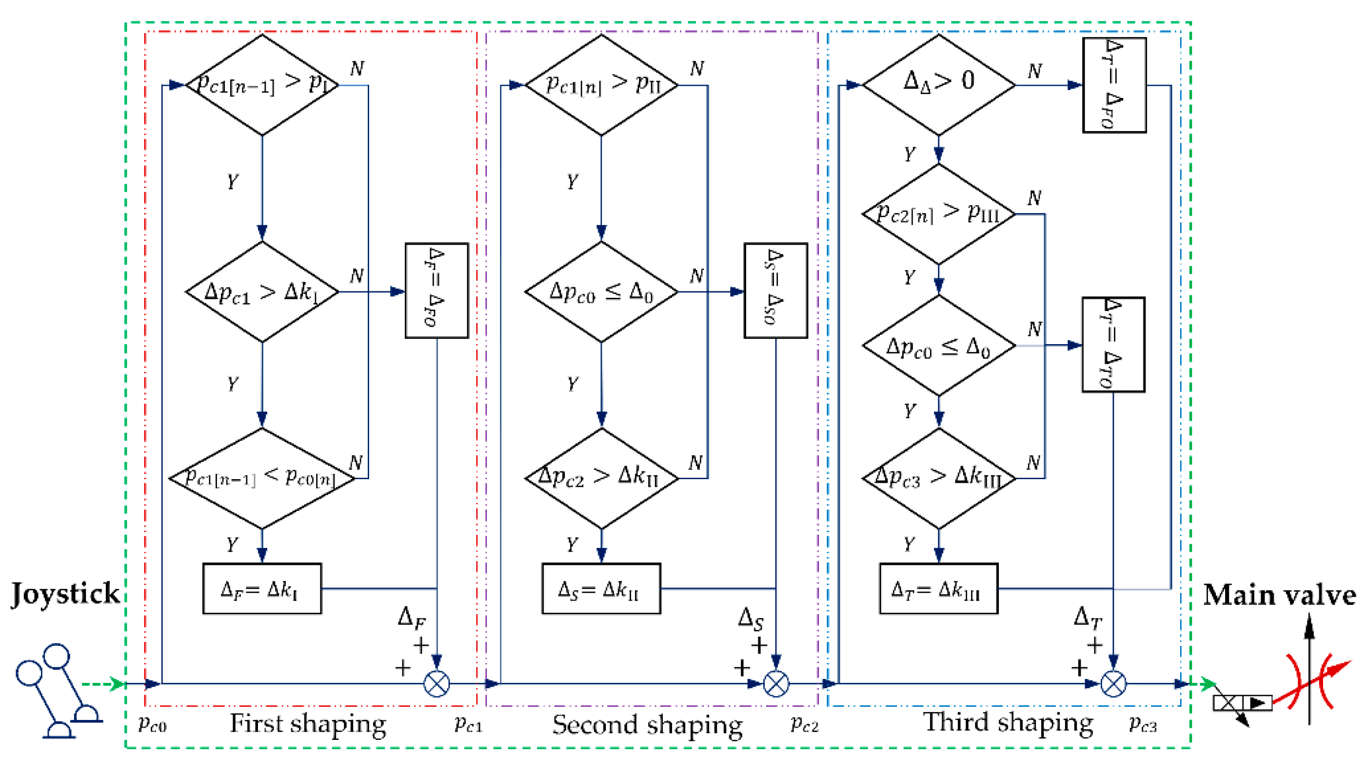
The input shaping control algorithm forms a desired five-stage signal by shaping the original main valve control signal three times, as shown in
Figure 6.
3.3.1. First Shaping
When main valve flow enters its control region, the actuator acceleration process enters the pressure build-up condition. At this time, the valve controller performs the first shaping on the original main valve control signal, and the algorithm is as follows:
where
is the first-shaped main valve control signal,
is equal to 0,
is the signal increment of
, and
n represents the
n-th sampling.
The activation conditions for the valve controller to perform the first shaping are as follows:
where
is the original, unshaped joystick-main valve control signal,
is taken as 0.5 times of the maximum valve of joystick-main valve control signal in this paper,
is the shaped main valve control signal increment of Stage II shown in
Figure 6.
When the relevant parameters meet (12), then
should be
; that is,
Otherwise,
should be
; that is,
Here, the first shaping of main valve control signal is completed.
3.3.2. Second Shaping
The purpose of the second signal shaping is to design the acceleration/angular acceleration in the inertia–acceleration condition.
Equation (8) can be written as
Then,
can be expressed as
According to (16), can be designed by adjusting main valve control signal slope , so as to reduce the motor overflow and pressure overshoot caused by the mismatch between the main valve flow growth rate and the desired .
The valve controller performs the second shaping on the original main valve control signal, and the algorithm is as follows:
where
the second-shaped main valve control signal and
is equal to 0, and
is the signal increment of
.
The activation conditions for valve controller to perform the second shaping are as follows:
where
is taken as 0.8 times of
,
is a set value used to judge whether main valve control signal reaches a constant state, and
is the shaped main valve control signal increment of Stage III shown in
Figure 6.
When the relevant parameters meet (18), then
should be
; that is,
Otherwise,
should be
; that is,
Here, the second shaping of the main valve control signal is completed.
3.3.3. Third Shaping
The purpose of the third signal shaping is to design the acceleration–stabilization time of the actuator.
The valve controller performs the third shaping on the original main valve control signal, and the algorithm is as follows.
where
is the third-shaped main valve control signal,
is equal to 0,
is the signal increment of
.
The activation conditions for the valve controller to perform the third shaping are as shown in (22) and (23):
where
is taken as 0.9 times of
, and
is the shaped main valve control signal increment of Stage III shown in
Figure 6.
When the relevant parameters cannot meet (23),
should be equal to
; that is,
When the parameters only meet (23),
should be equal to
; that is,
When the parameters meet (22) and (23),
should be equal to
; that is,
Here, the third shaping of main valve control signal is completed.
In summary, the main valve input shaping control logic for the acceleration process of large inertia hydraulic actuator is shown in
Figure 7.
4. Test and Analysis
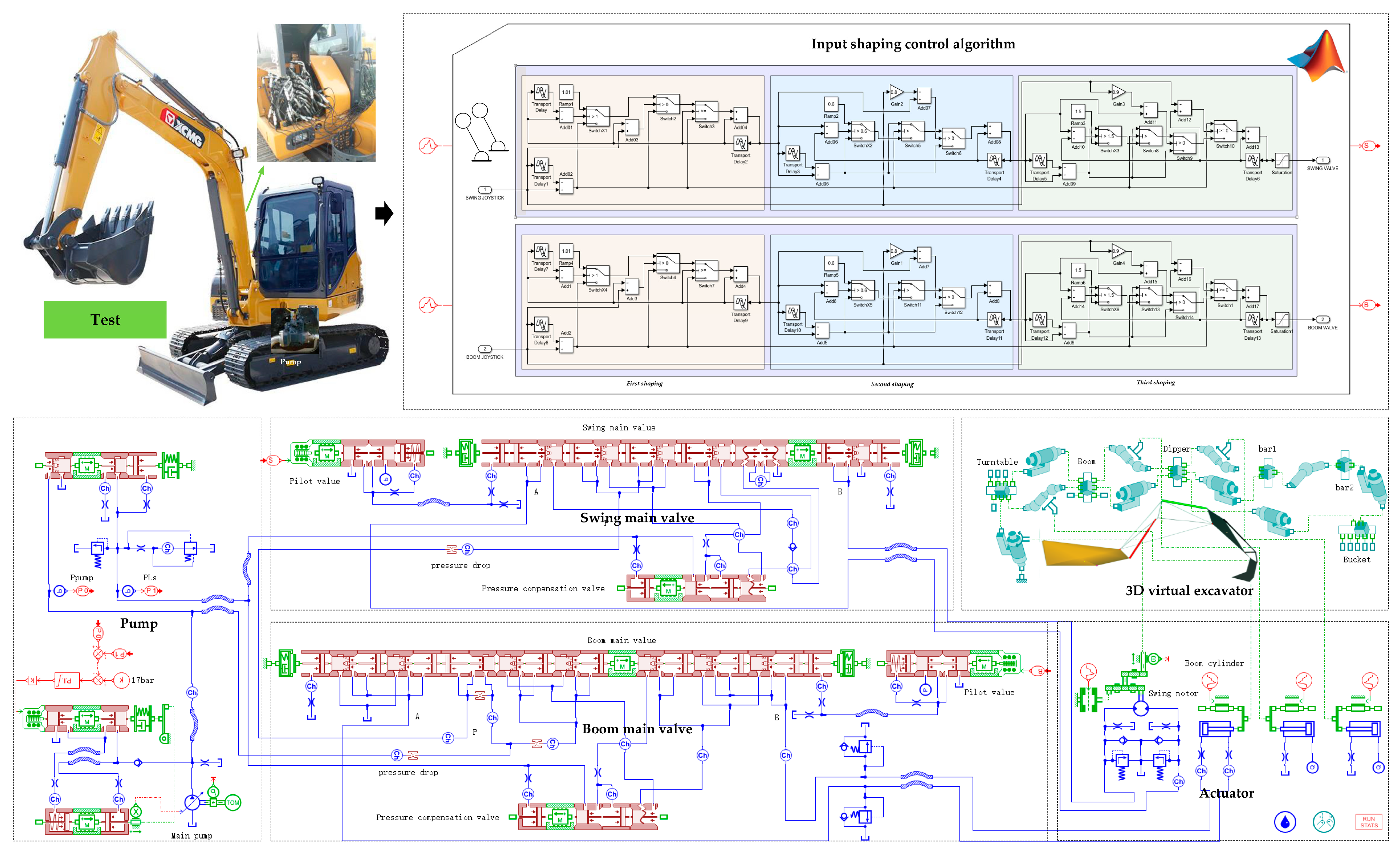
In order to verify the correctness and beneficial effects of the main valve input shaping control strategy, tests were carried out based on a 6-ton LUDV excavator, as shown in
Figure 8.
First, we tested the driving pressure characteristics of the swing motor and boom cylinder, and measured the key hydraulic–structural parameters of the LUDV excavator.
Next, we built a 3D virtual excavator based on the key parameters, and verified the virtual model according to the test data, so that it could accurately simulate the swing action and the boom lifting action.
Finally, based on the virtual excavator, we conducted SIL (software-in-the-loop) tests on the input shaping control algorithm, and compared the system operation characteristics before and after adopting the control algorithm so as to verify its correctness.
In addition, this paper provides some key parameters of the hydraulic components for reference, as shown in
Table 1.
4.1. Model Validation
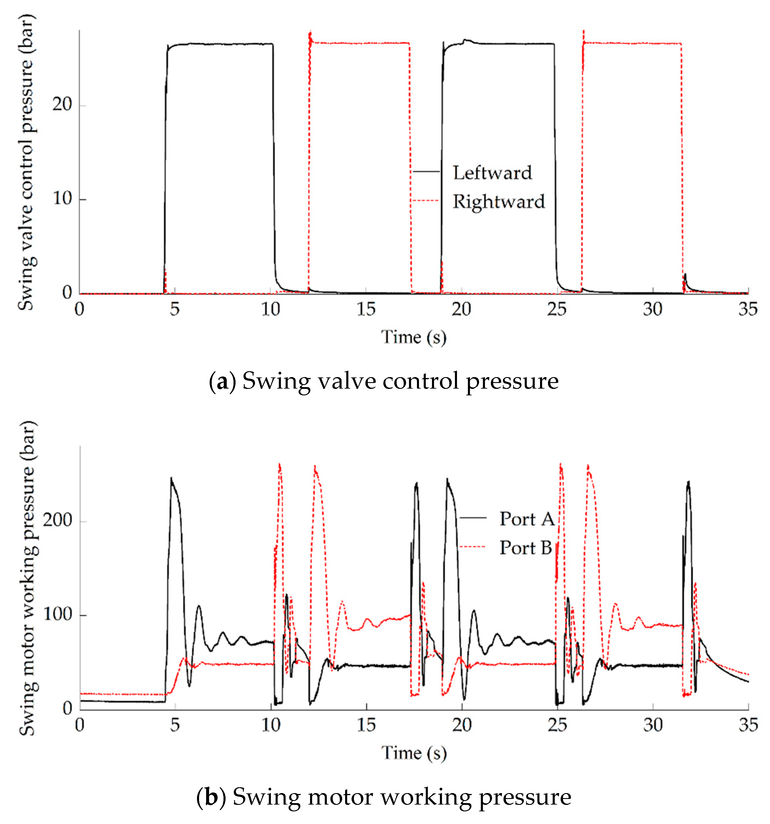
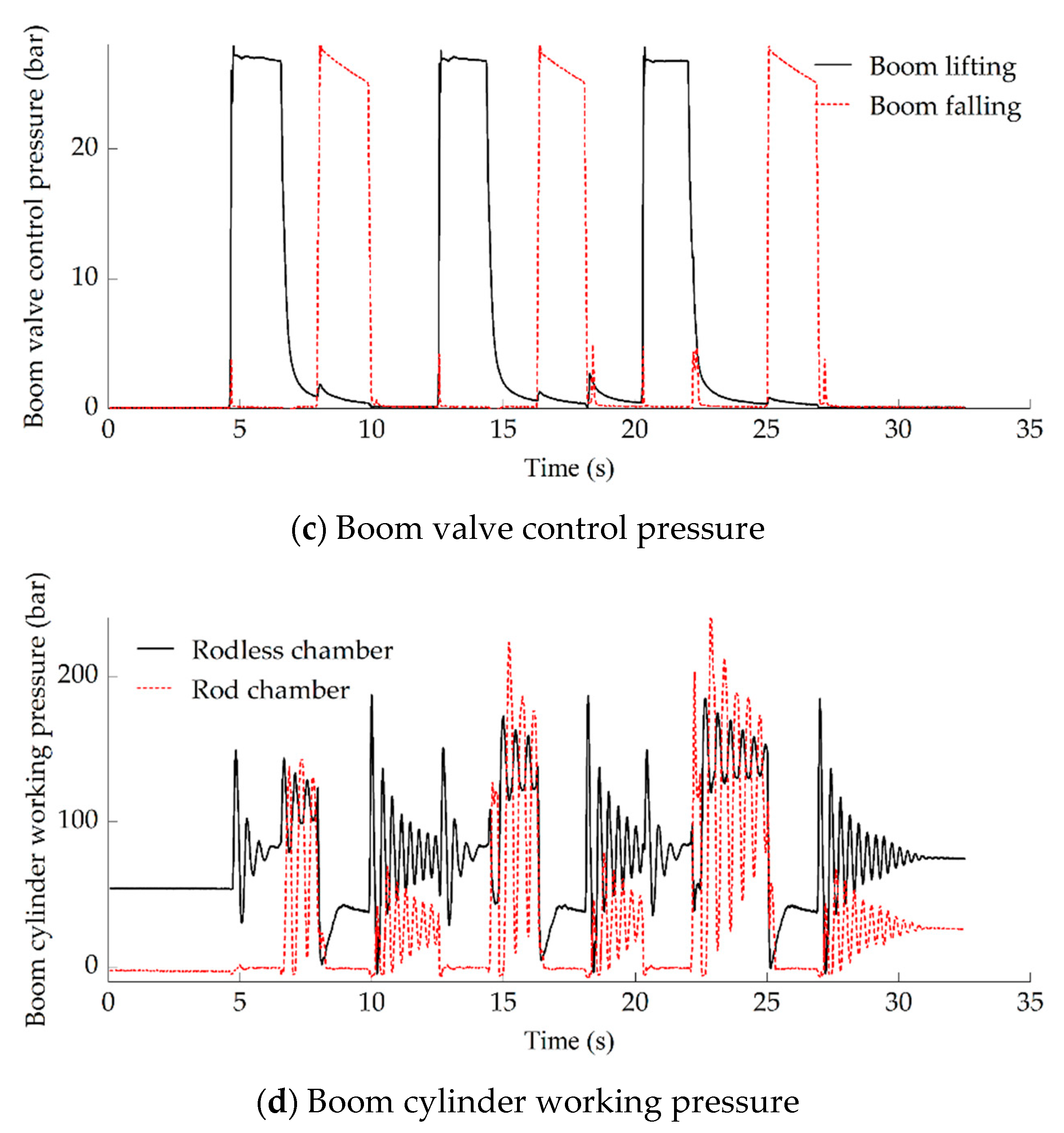
First of all, this paper tested the operating characteristics of the swing-boom system and obtained the characteristic curves of the swing valve control pressure, swing motor working pressure, boom valve control pressure, and boom cylinder working pressure, as shown in
Figure 9.
As shown in
Figure 9a,b, at about 4.5 s, the swing valve control pressure increased rapidly, Port A of the swing valve was opened, the valve flow flowed into Port A of the swing motor, and the turntable swung to the left. At about 10 s, the swing valve was closed and the motor was braked. At about 12 s, the flow of the main valve flowed into Port B of the swing motor, and the turntable swung to the right. At about 17.5 s, the swing valve was closed and the motor was braked. Then, we tested the left-right swing operation cycle again. In the swing work cycle, after the motor speed reached the desired value, there was a 60~90 bar pressure fluctuation in the drive chamber at about 6~7 s, 13~14 s, 20~21 s, and 27~28 s; this needs to be suppressed.
As shown in
Figure 9a,b, at about 4.5 s, boom valve control pressure increased rapidly, the valve flow flowed into the rodless chamber of the boom cylinder, and the boom was lifted. At about 7 s, the boom valve was closed and the cylinder was braked. At about 8 s, boom valve flow flowed into the rod chamber of the boom cylinder, and the boom fell. At about 10 s, the boom cylinder was braked. Then, we tested the boom lift–fall cycle twice. In the boom work cycle, there was an 80~100 bar pressure overshoot in the drive chamber during boom cylinder acceleration at about 4.5~6 s, 12.5~14 s, and 20~22 s; this needs to be optimized.
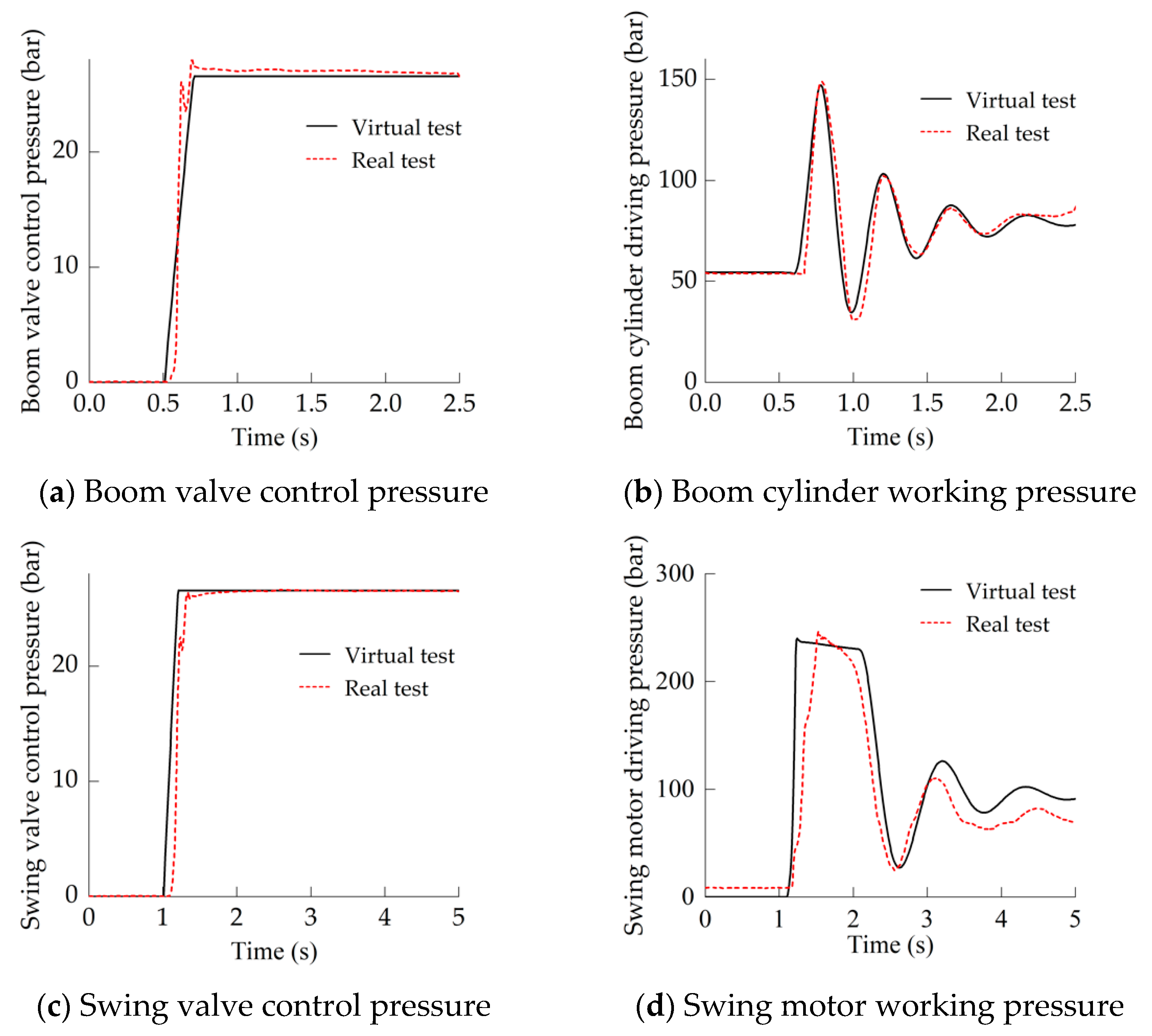
According to Formula (1), the driving pressure of the hydraulic actuator (swing motor or boom cylinder) determines its acceleration characteristics; thus, the key to verifying the correctness of the virtual excavator model is to check the consistency between the virtual characteristics and the real characteristics of actuator driving pressure. The slope signals shown in
Figure 10a,c are used to simulate the swing valve control pressure and boom valve control pressure, respectively, and the actuator driving pressure characteristics of the virtual excavator are consistent with the test results of the real excavator (
Figure 10b,d). Therefore, it can be determined that the virtual excavator can simulate the swing and boom lifting conditions of the real 6-ton LUDV excavator.
4.2. Ramp Response Analysis
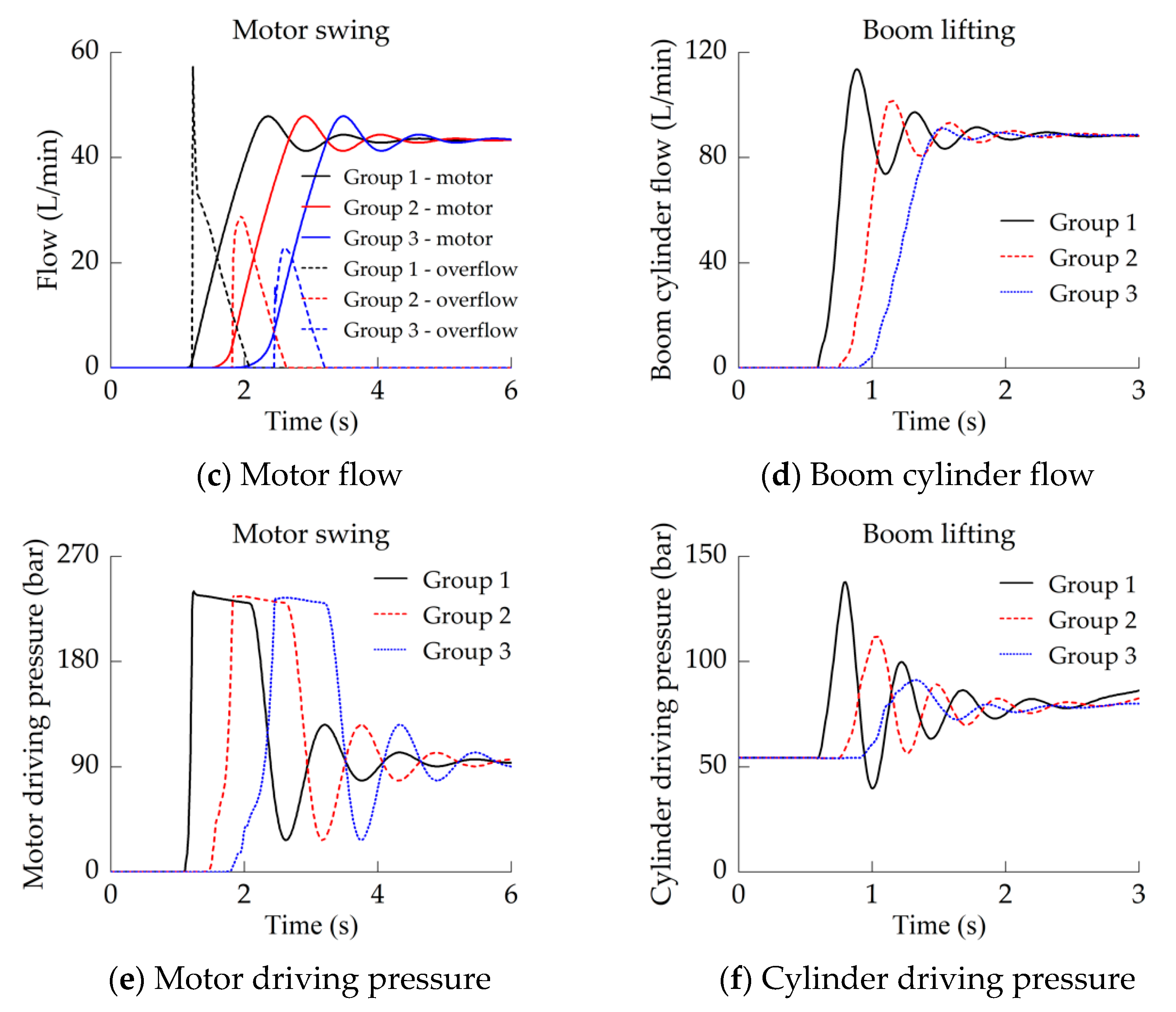
In this paper, three ramp signals with different slopes were used to simulate the swing/boom valve control signal, and the acceleration characteristics of the swing motor and the boom cylinder are shown in
Figure 11.
Response speed. As the main valve control signal (pressure) slope decreased, the opening time of the main valve orifice was delayed, and the pressure growth rate of the drive chamber decreased (
Figure 11e,f), which delayed the swing motor flow and boom cylinder flow (
Figure 11c,d), as well as the swing action or boom lifting action.
Dynamic stability. As the control signal slope decreased, the flow growth rate and the piston acceleration of the boom cylinder decreased, the pressure-flow stability of the boom cylinder was significantly improved; that is, the pressure-flow oscillation amplitude was reduced (
Figure 11d,f). However, due to the pressure-limiting effect of the motor relief valve, a slight reduction in the signal slope could not effectively improve the pressure-flow stability of the swing motor (
Figure 11c,e).
Motor overflow. As the control signal slope decreased, the swing valve flow growth rate decreased, while the motor flow growth rate was relatively constant, so the motor overflow was reduced (
Figure 11c). However, due to the excessive load inertia of the swing motor, the flow overmatching degree and the overflow were not significantly reduced.
In summary, if the human-joystick-main valve control signal is regarded as a ramp signal, it is difficult for it to meet the requirements of system responsiveness, stability, and efficiency at the same time by simply changing the slope of the ramp signal. Fortunately, the large-slope signal can meet the responsiveness requirements, and the small-slope signal can meet the stability and efficiency requirements. Thus, it is necessary to design the slope of main valve control signal in several stages.
4.3. Performance Optimization
4.3.1. Motor Swing
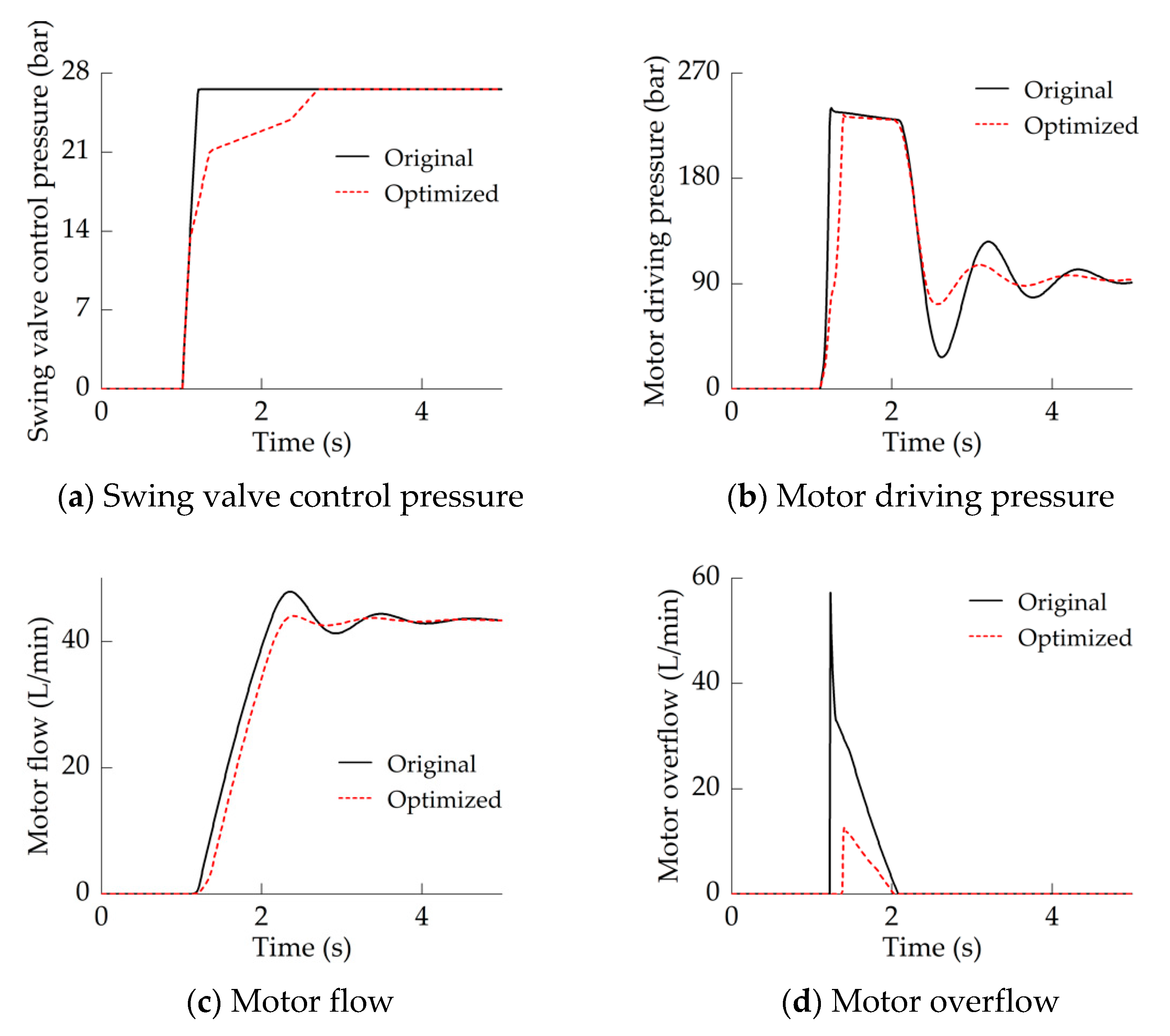
The acceleration characteristics of the swing motor when the motor load inertia was at its maximum value are shown in
Figure 12. The ramp signal (
Figure 12a) was used to simulate the joystick-main valve control signal when the joystick was operated quickly.
In the original system, after the swing valve-orifice was opened, its flow increased rapidly. Due to the large volume of the drive chamber, a certain response time was required to build up the pressure that could overcome the motor load (
Figure 12b). When the motor accelerated, its inertia load was very large, and it could not fully absorb the flow from the swing valve, resulting in motor overflow (
Figure 12d). When the motor reached its steady-state speed for the first time, due to the elastic modulus of hydraulic oil, the pressure in the drive chamber did not drop suddenly, but will drop at a certain speed. As a result, the drive chamber passively released the pressure energy of hydraulic oil to output power to the swing motor, which caused a flow overshoot (
Figure 12c). The flow overshoot inevitably causes the pressure in the chamber to drop and form a large pressure undershoot (
Figure 12b), which causes pressure oscillations and prolongs the acceleration–stabilization time (
Figure 12b,c).
In the optimized system, as shown in
Figure 6, the swing valve control signal was divided into 5 stages. The main valve input shaping control of Stage I and Stage II reduced the pressure-flow growth rate of the swing motor (
Figure 12b), but it barely affected the motor response speed. The shaping control of Stage III weakened the mismatch between the swing valve and the motor, and effectively reduced the motor overflow (
Figure 12d), at the same time; the inertia load was reduced through the advance adjustment, and the driving pressure was released in advance, which reduced the motor flow overshoot (
Figure 12c). The shaping control of Stage IV maintained the acceleration–stabilization time of the swing motor within 1.5 s (
Figure 12b,c); in addition,
is set to be greater than
to compensate for the motor inertia load, thereby weakening the pressure undershoot (
Figure 12b) and further improving the stability of the swing motor. In particular, at about 2.6 s, the driving pressure undershoot of the swing motor drops from about 72% to 24%.
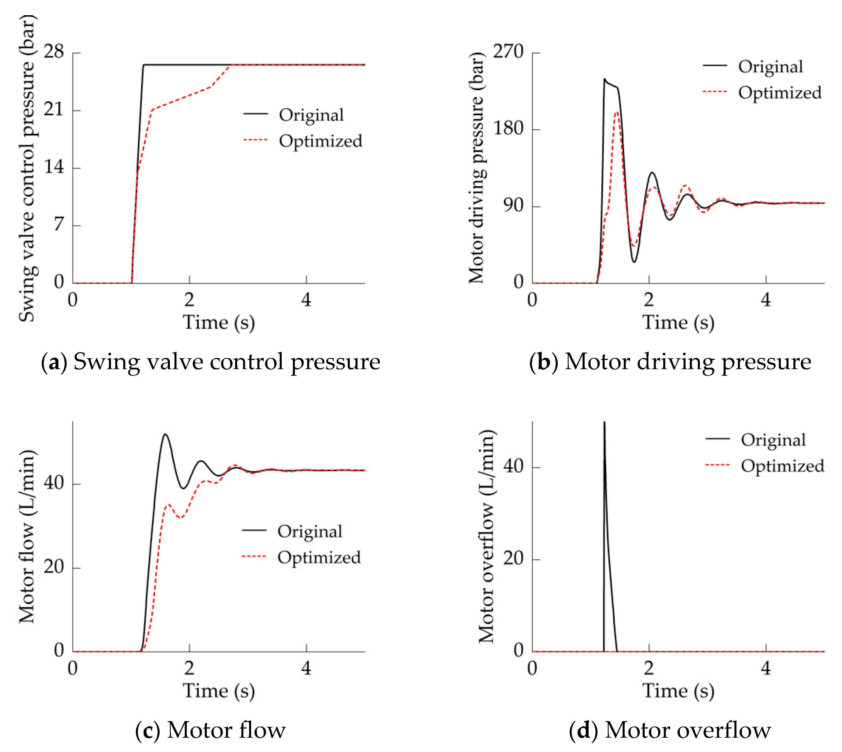
The difference between the minimum inertia and the maximum inertia of swing motor load is very large, and it is necessary to investigate the motor acceleration characteristics when the load inertia is at its minimum value. As shown in
Figure 13, the motor acceleration characteristics were similar to those shown in
Figure 12, namely, the motor flow stability were improved, and the overflow was eliminated. Significantly, in
Figure 13c, the motor flow oscillated slightly, and its stability was still relatively improved. Thus, when the motor load inertia was between its maximum and minimum, the optimization effect of the input shaping control strategy was always effective.
4.3.2. Boom Lifting
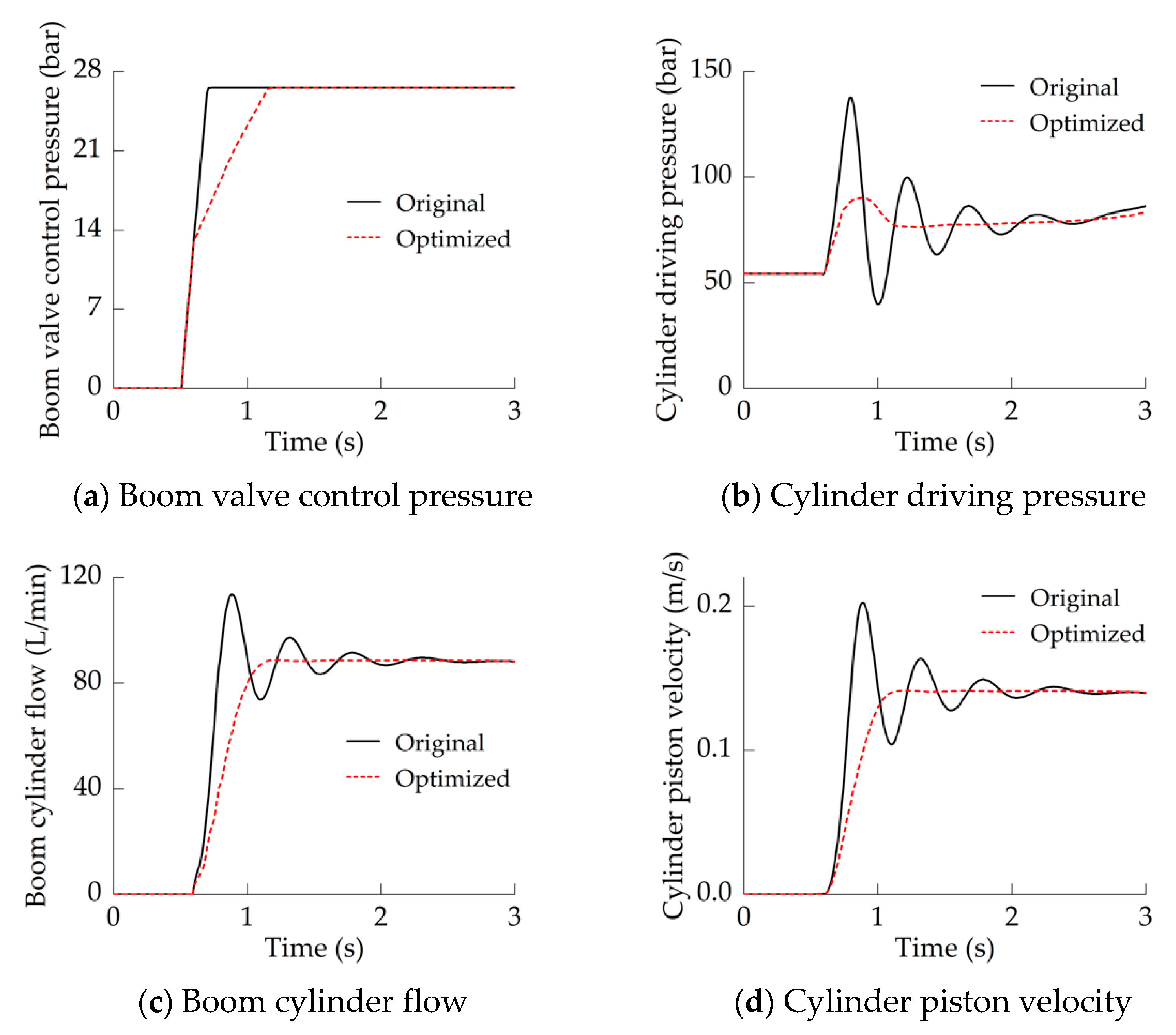
The acceleration characteristics of the boom cylinder when the excavator performed a boom lifting action are shown in
Figure 14. Similarly to the motor swing action, a ramp signal (
Figure 14a) was used to simulate the boom valve control signal.
In the original system, similarly to the swing motor, the boom cylinder also needs a certain response time. Compared with the motor, the inertia load of the boom cylinder is smaller, so the acceleration of the cylinder is relatively large and the acceleration time is shorter, which makes the cylinder produce a significant pressure overshoot (
Figure 14b). In addition, according to
Figure 12b,
Figure 13b and
Figure 14b, it can be seen that passively releasing the pressure in the drive chamber is not conducive to improving the pressure stability and prolonging the acceleration–stabilization time of the actuator (
Figure 14b,c).
In the optimized system, as shown in
Figure 6, the boom valve control signal is divided into 4 stages. Similarly to the swing motor, the main valve input shaping control of Stage I and Stage II hardly affects the cylinder response speed. The shaping control of Stage III can design the acceleration–dinertia load of the cylinder, which greatly reduces the driving pressure overshoot (
Figure 14b), and the pressure overshoot drops from about 80% to 16%. At the same time, the reasonable acceleration setting of the boom cylinder can release the driving pressure in advance and ease the pressure release process, thereby improving the softness of boom lifting action (
Figure 14c,d).
5. Conclusions
The large inertia hydraulic actuators of the existing LUDV excavator mainly suffer from large pressure overshoot, oscillation tendency, and low efficiency during its acceleration process, which is caused by the incompatibility of human-input characteristics, system control characteristics and load characteristics. In this paper, a concept is clarified through modeling analysis, that is, the main valve flow growth rate has a significant impact on the actuator acceleration performance; however, it is difficult to optimize the acceleration performance in all aspects by simply adjusting the signal slope. Thus, an open-loop main valve input shaping control strategy is proposed based on the inertia load characteristic and human-joystick input characteristic, which divides the actuator acceleration process into pressure build-up condition, inertia–acceleration condition and stable-flow regulation condition, and shapes the main valve control signal three times into a five-stage signal accordingly. In fact, we can regard the input shaping control as a modified design of human-input characteristics, so that it can better adapt to the system control characteristics and load characteristics. By properly setting the signal slope and switching point of the five-stage main valve control signal, it is possible to actively adjust the driving pressure build-up process, the actuator acceleration and the driving pressure release process, thereby suppressing the driving pressure overshoot, oscillation, and pressure overmatch/motor overflow, shortening the acceleration adjustment time of the actuator.
In addition, the main valve input shaping control strategy sacrifices a small part of the response time to improve the system stability. Moreover, the control strategy can only limit the slope of large-slope signals, so it can only be applied to the hydraulic motor/cylinder system with relatively large inertia load and quick push–pull input; thus, we can further study how to optimize the system performance under slow push–pull input. Although the control strategy has some shortcomings, for the excavator that has many quick joystick manipulations and does not require high speed/position control accuracy, the application of this sensorless and cost-friendly performance optimization scheme is undoubtedly a good choice.
Author Contributions
Conceptualization, W.F. and L.Z.; methodology, W.F.; software, W.F. and X.Y.; validation, Y.L.; formal analysis, Y.L.; investigation, L.Z. and W.F.; resources, X.Y.; data curation, X.Y.; writing—original draft preparation, W.F.; writing—review and editing, L.Z.; visualization, Y.L.; supervision, X.Y.; project administration, X.Y.; funding acquisition, L.Z. All authors have read and agreed to the published version of the manuscript.
Funding
This work was supported by the National Key R&D Program of China [Grant 2020YFB2009804], the National Key R&D Program of China [Grant 2018YFB2001201], the Science and Technology Research Project of Colleges and Universities in Hebei Province [Grant ZD2022052].
Data Availability Statement
Not applicable.
Conflicts of Interest
The authors declare no conflict of interest.
References
- Mahato, A.C.; Ghoshal, S.K. Energy-saving strategies on power hydraulic system: An overview. Proc. Inst. Mech. Eng. Part I J. Syst. Control Eng. 2021, 235, 147–169. [Google Scholar] [CrossRef]
- Do, T.C.; Dang, T.D.; Dinh, T.Q.; Ahn, K.K. Developments in energy regeneration technologies for hydraulic excavators: A review. Renew. Sustain. Energy Rev. 2021, 145, 111076. [Google Scholar] [CrossRef]
- Xu, B.; Cheng, M. Motion control of multi-actuator hydraulic systems for mobile machineries: Recent advancements and future trends. Front. Mech. Eng. 2018, 13, 151–166. [Google Scholar] [CrossRef]
- Padovani, D.; Rundo, M.; Altare, G. The working hydraulics of valve-controlled mobile machines: Classification and review. J. Dyn. Syst. Meas. Control 2020, 142, 070801. [Google Scholar] [CrossRef]
- Lantto, B.; Palmberg, J.O.; Krus, P. Static and dynamic performance of mobile load-sensing systems with two different types of pressure-compensated valves. SAE Trans. 1990, 99, 251–265. [Google Scholar]
- Lantto, B.; Krus, P.; Palmberg, J.O. Dynamic properties of load-sensing systems with interacting complex mechanical loads. J. Dyn. Syst. Meas. Control 1993, 115, 525–530. [Google Scholar] [CrossRef]
- Pedersen, H.C.; Andersen, T.O.; Hansen, M.R. Load Sensing Systems-A Review of the Research Contributions Throughout the Last Decades. In Proceedings of the 4th International Fluid Power Conference, Dresden, Germany, 25–26 March 2004; pp. 125–139. [Google Scholar]
- Wang, H.; Leaney, P.G. Modelling and energy efficiency analysis of a hybrid pump-controlled asymmetric (single-rod) cylinder drive system. Int. J. Hydromechatron. 2020, 3, 1–25. [Google Scholar] [CrossRef]
- Fu, W.; Yuan, X.; Li, Y.; Zhang, L. Research on Optimal Control of Excavator Negative Control System Based on Secondary Controllable Main Valve. IEEE Access 2022, 10, 7566–7573. [Google Scholar] [CrossRef]
- Huang, W.; Quan, L.; Huang, J.; Yang, J. Excavator swing system controlled with separate meter-in and meter-out method. Chin. J. Mech. Eng. 2016, 52, 159–167. [Google Scholar] [CrossRef]
- Lovrec, D.; Kastrevc, M.; Ulaga, S. Electro-hydraulic load sensing with a speed-controlled hydraulic supply system on forming-machines. Int. J. Adv. Manuf. Technol. 2009, 41, 1066–1075. [Google Scholar] [CrossRef]
- Cheng, M.; Xu, B.; Zhang, J.; Ding, R. Pump-based compensation for dynamic improvement of the electrohydraulic flow matching system. IEEE Trans. Ind. Electron. 2016, 64, 2903–2913. [Google Scholar] [CrossRef]
- Axin, M.; Eriksson, B.; Krus, P. Flow versus pressure control of pumps in mobile hydraulic systems. Proc. Inst. Mech. Eng. Part I J. Syst. Control Eng. 2014, 228, 245–256. [Google Scholar] [CrossRef]
- Jansson, A.; Palmberg, J.O. Separate controls of meter-in and meter-out orifices in mobile hyraulic systems. SAE Trans. 1990, 99, 377–383. [Google Scholar]
- Eriksson, B.; Palmberg, J.O. Individual metering fluid power systems: Challenges and opportunities. Proc. Inst. Mech. Eng. Part I J. Syst. Control Eng. 2011, 225, 196–211. [Google Scholar] [CrossRef]
- Abuowda, K.; Okhotnikov, I.; Noroozi, S.; Godfrey, P.; Dupac, M. A review of electrohydraulic independent metering technology. ISA Trans. 2020, 98, 364–381. [Google Scholar] [CrossRef]
- Hu, Q.; Zhang, H.; Tian, S.; Qin, X. Performances analysis of a novel load-sensing hydraulic system with overriding differential pressure control. Proc. Inst. Mech. Eng. Part C J. Mech. Eng. Sci. 2017, 231, 4331–4343. [Google Scholar]
- Axin, M.; Eriksson, B.; Krus, P. A hybrid of pressure and flow control in mobile hydraulic systems. In Proceedings of the 9th International Fluid Power Conference, Aachen, Germany, 24–26 March 2014; pp. 190–201. [Google Scholar]
- Cheng, M.; Zhang, J.; Xu, B.; Ding, R. An Electrohydraulic Load Sensing System based on flow/pressure switched control for mobile machinery. ISA Trans. 2020, 96, 367–375. [Google Scholar] [CrossRef]
- Cheng, M.; Luo, S.; Ding, R.; Xu, B.; Zhang, J. Dynamic impact of hydraulic systems using pressure feedback for active damping. Appl. Math. Model. 2021, 89, 454–469. [Google Scholar] [CrossRef]
- Ding, R.; Zhang, J.; Xu, B. Pump/valves coordinate control of the independent metering system for mobile machinery. Autom. Constr. 2015, 57, 98–111. [Google Scholar]
- Rath, G.; Zaev, E.; Babunski, D. Oscillation Damping with Input Shaping in Individual Metering Hydraulic Systems. In Proceedings of the 8th Mediterranean Conference on Embedded Computing, Budva, Montenegro, 10–14 June 2019; pp. 1–5. [Google Scholar]
- Singhose, W. Command shaping for flexible systems: A review of the first 50 years. Int. J. Precis. Eng. Manuf. 2009, 10, 153–168. [Google Scholar] [CrossRef]
- Sarafin, P. Input Shaping. Inf. Sci. Technol. Bull. ACM Slovak. 2018, 10, 1–12. [Google Scholar]
- Yuan, X.; Wang, W.; Zhu, X.; Zhang, L. Theoretical Model of Dynamic Bulk Modulus for Aerated Hydraulic Fluid. Chin. J. Mech. Eng. 2022, 35, 121. [Google Scholar] [CrossRef]
| Publisher’s Note: MDPI stays neutral with regard to jurisdictional claims in published maps and institutional affiliations. |
© 2022 by the authors. Licensee MDPI, Basel, Switzerland. This article is an open access article distributed under the terms and conditions of the Creative Commons Attribution (CC BY) license (https://creativecommons.org/licenses/by/4.0/).
