Article

Design and Application of Non-Circular Gear with Cusp Pitch Curve

1
School of Mechanical Engineering, Zhejiang Sci-Tech University, Hangzhou 310018, China
2
College of Mechanical and Electrical Engineering, Wuyi University, Wuyishan 354300, China
3
The Key Laboratory for Agricultural Machinery Intelligent Control and Manufacturing of Fujian Education Institutions, Wuyishan 354300, China
4
Key Laboratory of Transplanting Equipment and Technology of Zhejiang Province, Hangzhou 310018, China
*
Author to whom correspondence should be addressed.
Machines 2022, 10(11), 985; https://doi.org/10.3390/machines10110985
Submission received: 2 October 2022 / Revised: 23 October 2022 / Accepted: 25 October 2022 / Published: 28 October 2022

Abstract

:
To solve the design problem of non-circular gears with cusp pitch curves, this paper proposed a new variable-involute and incomplete variable-cycloid composite tooth profile (VIIVC-CTF), deduced the new VIIVC-CTF mathematical model, and constructed the conjugate gear model based on the envelope method. The design software of the non-circular gear with a cusp pitch curve was developed based on MATLAB. The variation law of rolling radius on an incomplete cycloid profile and its characteristics such as pressure angle and radius of curvature were analyzed. The variation relationship of the rolling radius on the meshing line and the contact ratio of the VIIVC-CTF were studied. The variation relationship of incomplete variable-cycloid profile shape, pressure angle, and curvature radius corresponding to different elliptical eccentricities were analyzed. The meshing analysis of the non-circular gear transmission mechanism was carried out based on virtual software. A comparison of the consistency of the theoretical value and simulation value of the transmission ratio curve verified that the tooth profile design method was feasible, and the VIIVC-CTF was applied to the seedling pick-up mechanism of the non-circular gear planetary gear train. Through the seedling picking experiment of the seedling pick-up mechanism, the feasibility of the application of the VIIVC-CTF was verified.

1. Introduction

Non-circular gears are often used to achieve a specific transmission ratio curve, but non-circular pitch curves with cusps cannot be designed by using a normal involute tooth. The design of pitch curves with cusps has always been a technical problem to be solved in non-circular gear transmission. On this basis, this paper proposed a new design method for the VIIVC-CTF and designed a non-circular gear transmission mechanism of a non-circular pitch curve with cusps.
Wang et al. [1] proposed a composite tooth profile composed of a tooth top arc, tooth waist involute, and tooth root arc, and applied it to the root gear vacuum pump. Choi [2] proposed a full cycloid cylindrical gear with a variable rolling radius of the tooth root and tooth top and applied it to a cycloid rotor pump. To calculate the normal contact stiffness accurately, Chen [3] constructed a fractal contact stiffness model considering friction factors and obtained the relationship between normal contact stiffness, normal load, and material performance parameters. Normal contact stiffness increased with the increase in curvature radius and decreased with the increase in friction coefficient and roughness. He [4] proposed a method based on the Monte Carlo method to calculate the contact stiffness of cycloidal pinwheel and explored the variation relationship of cycloidal pinwheel contact stiffness. Chung [5] established the analytical model of the meshing stiffness and static transmission error of helical gear pair and verified the effectiveness of the model through the finite element method, which is more effective than the traditional model calculation. A calculation method of dynamic excitation of 3D modified double helical gear pair considering the actual contact state was proposed and the tooth surface equation of 3D modified double helical gear was deduced. Yang [6] constructed the calculation method of time-varying meshing stiffness and the calculation formula of meshing impact force of double helical gear pair after practice and discussed the influence of helix angle and correction parameters on meshing impact force. Sun [7] constructed a time-varying mesh stiffness optimization analysis model considering coupling correction and compared it to the existing models. The finite element method verified that the comprehensive practice calculation method has high calculation accuracy and efficiency. Choi [8] evaluated the influence of tooth top and tooth root on the optimization results of gear macro geometric design. By applying the same tooth top and tooth root length to the gear and rack, Choi carried out optimization including tooth top and tooth root variables, and completed the optimization of gears with different tooth top and tooth root lengths. Benaïcha [9] established a multibody contact model based on the augmented Lagrangian method and calculated the static transmission error without considering the position and direction of the contact line. Korta [10] et al. proposed an optimization method to reduce the peak value of contact stress and static transmission error of gear pair through tooth shape cultivation. Kim et al. [11] took the minimum gear mass, low noise (peak value of static transmission error), and high meshing efficiency as the optimization objectives; took the normal modulus, tooth width, helix angle, pressure angle, number of teeth, addendum, and root coefficient as the optimization variables to compare the optimization results of different objective function combinations; and finally determined the geometric state of helical gear. Zheng [12,13] discussed the manufacture of circular gears, established the mathematical model of non-uniform measurement of the side roll of circular gears, and designed a rapid measurement device for non-circular gears. The transmission principle and mechanical properties of non-circular gears with variable center distance were systematically revealed, and the mathematical model and motion relationship of variable center distance were established based on screw theory. Lin [14,15] proposed a new type of gear pair for variable transmission ratio transmission between parallel shafts, that is, non-circular cycloid pinwheel transmission, and expounded the formation principle of a conjugate tooth profile of a non-circular cycloid pinwheel. The profile equation of the non-circular needle gear was established. The correctness of the gear transmission principle and design was verified by comparing the simulation experimental results with the theoretical calculation results. In addition, a new type of gear transmission based on spatial meshing theory was proposed, which can realize not only the simple motion transmission between orthogonal axes but also the compound motion of rotation and axial translation between orthogonal axes. The experiment proved that the gear design method is reasonable. Mundo [16] established a gear contact model based on penetration and carried out accurate, efficient tooth surface contact analysis and error analysis for spiral bevel gears. Dooner [17] proposed an approximation method of the equivalent cylindrical gear to an approximate straight bevel gear, developed a non-circular gear design platform for any tooth profile based on the envelope method, and calculated the no-load transmission error. Litvin [18] proposed an improved worm gear transmission mode, which reduces transmission error and is beneficial to improving the contact ratio compared with the existing methods. The transmissions of no-load and load were analyzed by using the tooth surface contact analysis method, which proved the feasibility of the design method. Huang [19,20] modified the critical area formula, contact area formula, and stiffness formula of elastic–plastic deformation considering friction by introducing the influence of friction factors. Together with the contact point area distribution formula of the cylindrical joint surface, the fractal model of normal contact stiffness suitable for micro-segment gear teeth was deduced. Chen [21] proposed a parallel axis gear with a zero sliding rate and steady-state meshing characteristics and studied the meshing characteristics of parallel axis gear, including sliding rate, meshing model, and meshing frequency. The inherent impact and meshing errors of gear nodes were compared with those of involute transmission. Krawiec [22,23] proposed a measurement methodology for nontypical cog belt pulleys, conducted experimental investigations, and presented a set of directions for process engineers manufacturing these pulleys. Furthermore, he presented the rapid prototyping methods of models of cog belt pulleys with non-circular envelopes, and the evaluation method of manufacturing accuracy of cog belt pulleys, which were applied in uneven running belt transmissions. Medvecká-Beňová [24] presented the design for the shape of a pitch outline for a specific requirement, that is, continuous change in gear ratio during one rotation. Maláková [25] presented the design of a suitable gear transmission with a continuously changing gear ratio in the range from 0.5 through 1.0 to 2.0 and back during one revolution of intermeshing gears, according to demands specified for a practical application. Cristescu [26] applied finite element analysis to the gear entity model to study the influence of the transmission ratio definition parameters on the gear tooth bending state, which is the standard for further optimizing the design of multi-speed gears. Niculescu [27] introduced a kinematics analysis method for the discharge gate of a billet reheating furnace driven by a non-circular gear. Nezir [28] presented a design method of non-circular gears that uses the same tools (rack cutter, hob, and gear shaper cutter) that are used to manufacture circular gears to obtain the envelope of the gear tooth surface cutter family. Several non-circular gear transmission devices that realized the twice unequal amplitude fluctuation of transmission ratio in the cycle were proposed by our research group [29,30], such as a combination non-circular gear transmission mechanism, in which the driving gear was composed of an incomplete non-circular gear and rack and the driven gear was composed of a partial non-circular gear and elliptical gear. However, in order to realize the transmission ratio curve, there are cusps on the pitch curve that cannot be avoided, so the design method of composite gear was adopted to realize the non-circular gear design of the cusp pitch curve. A non-circular gear with a cusp pitch curve can also be used in seedling taking mechanisms and transplanting mechanisms.
To sum up, using the new tooth profile to design a non-circular gear with a cusp pitch curve has not been found yet. In view of the design problem of non-circular gears with cusp pitch curves [31], the research group used the composite gear design method to design a non-circular gear with a cusp pitch curve at the early stage. The non-circular gear designed by this method has high quality and low precision, and its transmission accuracy is greatly affected by processing and assembly. At the early stage, the non-circular gear of the pitch curve with a small curvature radius was designed by use of the involute and cycloid composite tooth profile [32]. This involute and cycloid composite tooth profile has a cusp at the tooth profile connection of the pitch curve, so using micro-segments was necessary to modify the involute and cycloid at the tooth profile connection slightly. In order to design a non-circular gear with a small curvature radius pitch curve and avoid the micro modification of involute and cycloidal tooth profiles, the team also proposed a variable-involute and variable cycloidal composite tooth profile to design a non-circular gear of a pitch curve with a small curvature radius [33]. The above design methods cannot solve the design problem of non-circular gears with cusp pitch curves. This paper presents a design method for the VIIVC-CTF non-circular gear, realizes the design of a non-circular gear with a cusp pitch curve, avoids the micro modification of the involute and cycloid tooth profile at the tooth profile connection of the pitch curve, and realizes the smooth connection of the variable-involute and variable-cycloid tooth profiles.

2. Design Principle of VIIVC-CTF

Figure 1a shows that this research takes the combined pitch curve of the straight line and the ellipse as an example. The non-circular pitch curve IAJDK near cusp J cannot generate a normal involute tooth profile. The non-circular pitch curve AI is designed by the involute tooth profile and the non-circular pitch curve AJ is designed by using the incomplete cycloid tooth profile. In Figure 1a, cycloid AE (cycloid 1) is the incomplete cycloid profile shape of the standard rolling circle. Similarly, for the JK part of the pitch curve, the involute tooth profile and incomplete cycloid tooth profile are used to design the non-circular pitch curve DK and non-circular pitch curve DJ, respectively, as shown in cycloid DF (cycloid 4) in Figure 1a. However, the tooth profiles AG and AE have an unsmooth connection at point A (DH and DF also have an unsmooth connection at point D). In this research, a design method for the VIIVC-CTF is presented by changing the pressure angle of the involute and cycloid at the joint of the pitch curve so they are equal, and the tooth profiles of the involute and cycloid are smooth at the joint of the pitch curve. When rolling circle O2 is not a standard rolling circle but an ellipse, the obtained tooth profile is an incomplete variable-cycloid tooth profile. Furthermore, the involute tooth profiles AG and DH are designed as variable-involute tooth profiles [33], such as in Figure 1b. Connecting the apex EF of the cycloid tooth profile, the design of the cusp pitch curve of tooth profile GAEFDH is realized.

2.1. Variable-Involute Tooth Profile of Non-Circular Gear with Incomplete Pitch Curve

Figure 2 shows that the non-circular pitch curve of the driving gear is composed of an elliptical JABM and straight line MCDJ, in which pitch curves AB and CD are designed by the involute tooth profile, and the pitch curves AJ, DJ, CM, and MB are designed by the incomplete cycloid tooth profile. The coordinates of the non-circular pitch curve (xjqx, yjqx), the number of teeth of the non-circular gear (z), the number of teeth of the gear shaping cutter (z0), and the tooth profile at the pitch curve pressure angle of the gear shaping cutter (αs) are assumed to be known. According to the geometric relationship, the curvature center coordinates of the non-circular pitch curve can be obtained from the non-circular pitch curve coordinates, as shown in Equation (1):
{ x qlzx = x jqx y jqx [ 1 + ( y jqx ) 2 ] y jqx y qlzx = y jqx + 1 + ( y jqx ) 2 y jqx
where xjqx and yjqx are the horizontal and vertical coordinates of the non-circular pitch curve, yjqx = dyjqx/dxjqx, yjqx = d2yjqx/(dxjqx)2, respectively.
According to the arc length S of the non-circular pitch curve and the number of teeth z, the modulus of the non-circular gear m = S/(zπ) can be obtained. According to the meshing properties of the gear, the modulus of the gear shaping cutter m0 = m can be obtained. Uniting with the number of teeth z0, the pitch radius of gear shaping cutter rj = m0z0/2 can be obtained. According to the pressure angle of the tooth profile of the non-circular gear pitch curve α0, the base circle radius of the gear shaping cutter rjj = rjcos(α0) can be solved. As the gear shaping cutter pitch circle makes pure rolling without sliding along the non-circular pitch curve, the gear shaping cutter rotation center generates a path accordingly. The offset of this path relative to the non-circular gear pitch curve is the gear shaping cutter pitch radius rj, and the three points of the non-circular pitch curve curvature center, the non-circular pitch curve, gear shaping cutter pitch meshing point M2, and the gear shaping cutter rotation center I, are collinear at each time. When the non-circular pitch curve is convex or concave, the coordinates of gear shaping cutter rotation center I can be obtained according to the simultaneous equations of three-point collinearity:
{ x I x jqx x jqx x qlzx = r j ρ y I y jqx y jqx y qlzx = r j ρ { x I = r j ( x jqx x qlzx ) ρ + x jqx y I = r j ( y jqx y qlzx ) ρ + y jqx
ρ = ( x jqx x qlzx ) 2 + ( y jqx y qlzx ) 2
where rj is the pitch circle radius of the gear shaping cutter; rjj is the base circle radius of the gear shaping cutter; xI and yI are the abscissa and ordinate of the gear shaping cutter rotation center, respectively. The base circle radius of the gear shaping cutter is shown in Equation (4).
r b = r cos ( α 0 )
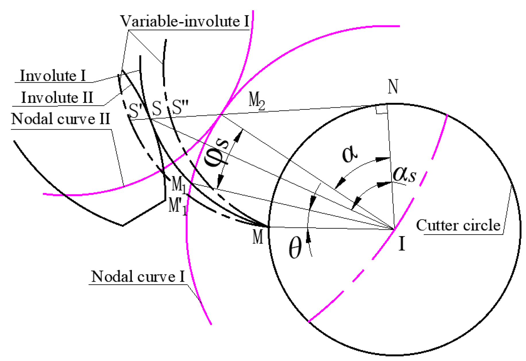
Figure 3 shows that the generating angle of the pitch circle of the gear shaping cutter can be obtained according to the gear meshing principle θ = tan(α0) - α0. The gear shaping cutter pitch circle starts from the initial position and rolls the arc length counterclockwise along the non-circular pitch curve ds (i.e., the arc length of M1M2 is ds), and then the angle of M1IM2 can be obtained (i.e., φs = ds/r). According to the gear meshing principle, the angle of M1IM2 is equal to α, and the straight line of SN is equal to the arc length of MN. The straight line of SN can be obtained by the product of the rb and the sum of θ, φs, and α0. In the triangle of SIN, the straight line of SI can be obtained by the square operation of the quadratic sum of SN and rjj. The pressure angle of the meshing point of the tooth profile of the gear shaping cutter rolling αs = tan−1(θ + φs + α0), so the angle of SIM2 is obtained by the difference between αs and α0 in the triangle of SIM2. The M2 coordinate of the meshing point and the I coordinate of the gear shaping cutter rotation center are known (and M2I = rj), so the coordinates of the tooth profile meshing point S relative to the gear shaping cutter rotation center I (xSI, ySI) are solved:
[ x SI y SI ] = [ cos ( SIM 2 ) sin ( SIM 2 )   sin ( SIM 2 ) cos ( SIM 2 ) ] [ r k ( x jqx ( M 2 ) x I ) / r j r k ( y jqx ( M 2 ) y I ) / r j ]
The coordinates of meshing point S of the tooth profile can be obtained according to Equation (5):
{ x S = x S I + x I y S = y S I + y I
where xSI and ySI are the abscissa and ordinate of the tooth profile meshing point S relative to gear shaping cutter rotation center I, respectively; xs and ys are the abscissa and ordinate of the variable-involute tooth profile, respectively; f(u) is the slip coefficient of the variable-involute tooth profile; rk is the radius of the gear shaping cutter, r k = f ( μ ) r b 2 + S N ¯ 2 .

2.2. Incomplete Cycloid Tooth Profile of Non-Circular with Incomplete Pitch Curve

Given the curvature center of the non-circular pitch curve, the meshing point S between the non-circular pitch curve and the pitch circle of the gear shaping cutter and the rolling rotation center I2 are collinear. The coordinates of the rolling rotation center I2 can be obtained according to the simultaneous equations of the collinearity of three points.
r gy = S 2 π n = ρ d θ 2 π n r = r gy ( a 1 cos ( θ ) ) 2 + ( b 1 sin ( θ ) ) 2
{ x I 2 x j x j x q = r ρ y I 2 y j y j y q = r ρ { x I 2 = r ( x j x q ) ρ + x j y I 2 = r ( y j y q ) ρ + y j
[ x I 2 y I 2 ] = [ r ( x j x q ) ρ r ( y j y q ) ρ ] + [ x j y j ]
{ x I 2 = x j + ( x j x q ) f r ( x j x q ) 2 + ( y j y q ) 2 y I 2 = y j + ( y j y q ) f r ( x j x q ) 2 + ( y j y q ) 2
where xj and yj are the pitch curve coordinates; xq and yq are the coordinates of the curvature center corresponding to the coordinate points of the pitch curve; f is the judgment coefficient of the concave–convex pitch curve (when the pitch curve is non-circular, the pitch curve has an outer convex and an inner concave, outer convex f = 1, inner concave f = -1); xI2 and yI2 are coordinates of the center of the rolling circle; θ0 is the self-rotation angular displacement; S is the arc length of the tangent pitch curve of the pure rolling of the rolling circle; ρ is the radius of curvature corresponding to pitch curve point; n is the multiple of the whole rolling circle of the rolling circle; rgy is the radius of the standard rolling circle; a1 and b1 are the coefficients of the long half axis and the short half axis of the ellipse of the variable-cycloid tooth profile, respectively; r is the polar diameter of the cycloid tooth profile; θ is the revolution displacement.
Given that the rolling circle rolls purely on the pitch curve, that is, when the rolling circle revolves, the rotation angle of the rolling circle that shifts with the rotation of the rolling circle θ0 has quadrant transformation, its formula is shown in Equation (11).
θ 0 = arctan ( y I 2 y q x I 2 x q )
The coordinates of the incomplete variable-cycloid tooth profile are shown in Equation (12).
r b = [ x b y b 1 ] = [ r cos ( θ + θ 0 + π ) + x I 2 r sin ( θ + θ 0 + π ) + y I 2 1 ]
where xb and yb are the incompletely variable-cycloid tooth profile coordinates.

2.3. Design of Non-Circular Gear Transmission Mechanism with Cusp Pitch Curve

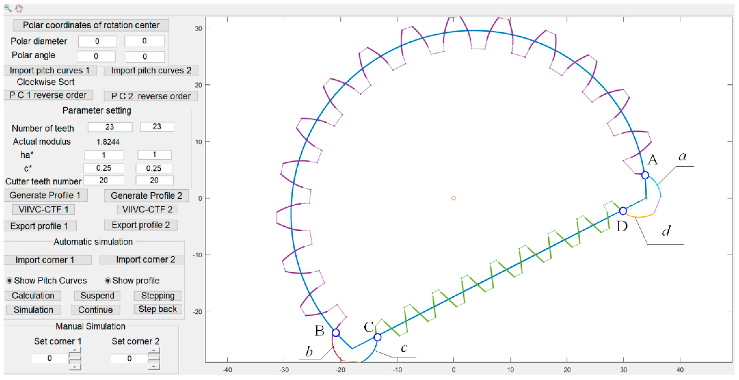
According to the design principle of non-circular VIIVC-CTF, the flow chart of the auxiliary software development of a non-circular gear with a cusp pitch curve is shown in Figure 4. Assume the involute pitch is h and the tooth thickness of the incomplete variable-cycloid composite tooth profile is hvc. In order to ensure that the strength of the designed VIIVC-CTF is feasible and the tooth root is not undercut, the tooth thickness of the VIIVC-CTF should be guaranteed within a certain design range. This paper sets hvc ∈ [0.8h, 1.2h]. The author develops the VIIVC-CTF design software with a cusp pitch curve. Figure 5 shows that a non-circular gear with a cusp pitch curve is designed.

3. Tooth Profile Characteristic of a Non-Circular Gear with the VIIVC-CTF

To design the tooth profile that meets the transmission requirements and avoids a cusp at the connection between the incomplete cycloid profile and the involute profile, the variation law of the incomplete cycloid profile and the variation relationship between pressure angle and curvature radius are analyzed by examining different rolling radii. The variable-cycloid tooth profile of elliptical rolling is connected to the variable-involute tooth profile to realize the continuous connection between the incomplete variable-cycloid tooth profile and the variable-involute tooth profile. The pressure angle or radius of curvature of the incomplete variable-cycloid tooth profile is equal to that of the variable-involute tooth profile at the joint of the pitch curve.

3.1. Tooth Profile Shape on Incomplete Cycloid Tooth Profile Based on Rolling Radius

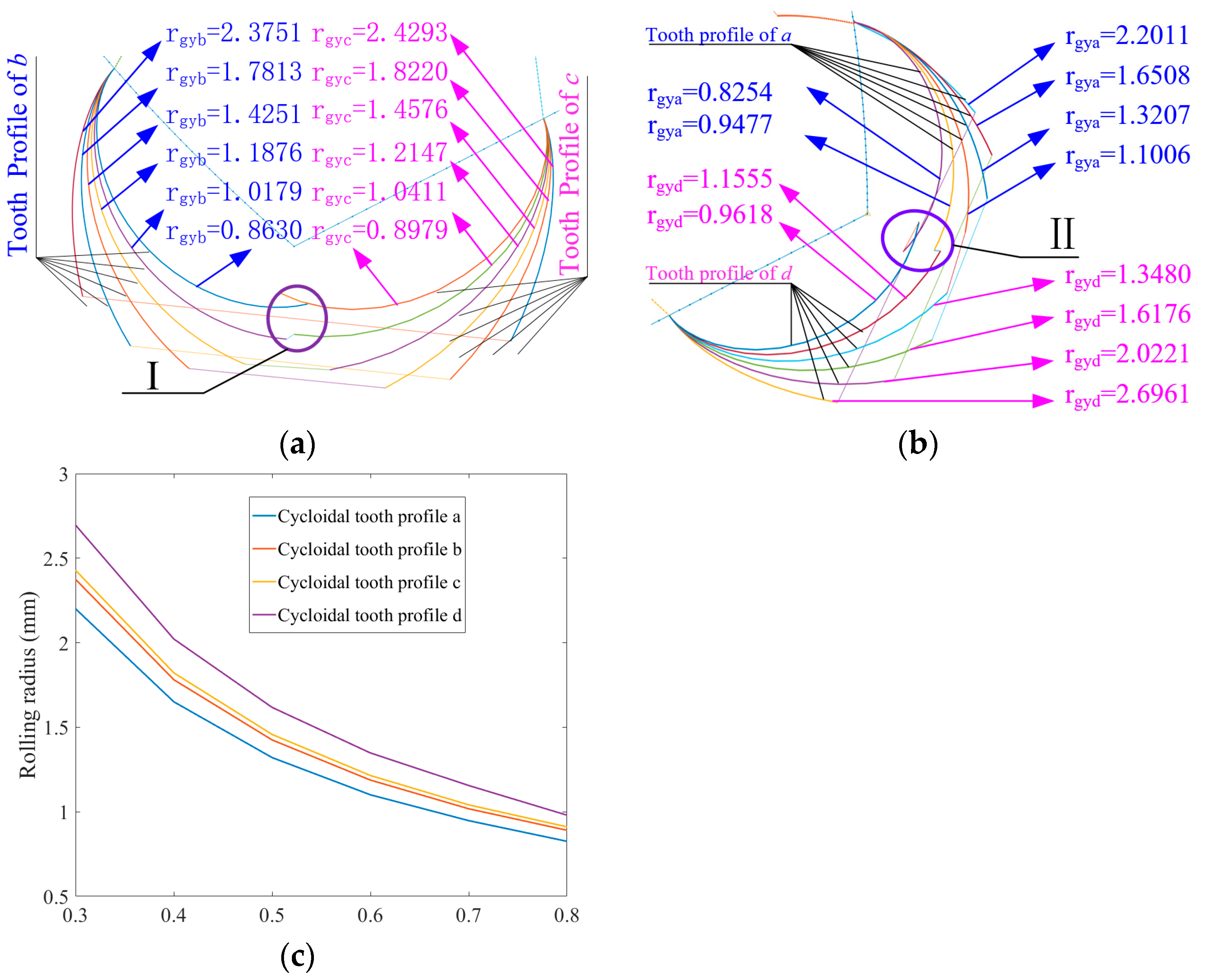
The shape of the incomplete cycloid tooth profile changes with the standard rolling radius of the cycloid gear. Figure 6 shows the shape of incomplete cycloid tooth profile bc and ad under different rolling radii. Due to the pitch curve length required for the incomplete cycloid tooth profile design being fixed, the rolling radius increases and the number of rolling cycles decreases. The variation relationship is shown in Figure 6c.
Figure 6 shows that the addendum of tooth profile bc decreases with the increase in rolling radius, but a very small rolling radius leads to the intersection of tooth profiles, resulting in the inability to design the pitch curve completely (i.e., the correct transmission requirements of a non-circular pitch curve cannot be realized). As shown in Figure 6a, when the rounding radius of the tooth profile bc is I (rgyb = 1.0179, 0.863 mm, and rgyc = 1.0411, 0.8979 mm), the tooth profile bc intersects, which will cause the non-circular gear to fail to drive normally. Similarly, the addendum of the tooth profile ad decreases with the increase in the rolling radius. A very small rolling radius also leads to the intersection of tooth profiles and cannot completely design the pitch curve. As shown in Figure 6b, when the rounding radius of the tooth profile ad is II (rgya = 0.9477, 0.8254 mm, and rgyd = 1.1555, 0.9618 mm), the tooth profile ad intersects, which will cause the non-circular gear to fail to drive normally. Figure 6c shows that the rolling radius of the incomplete cycloid tooth profile decreases with the increase in the number of rolling cycles.

3.2. Contact Ratio of VIIVC-CTF

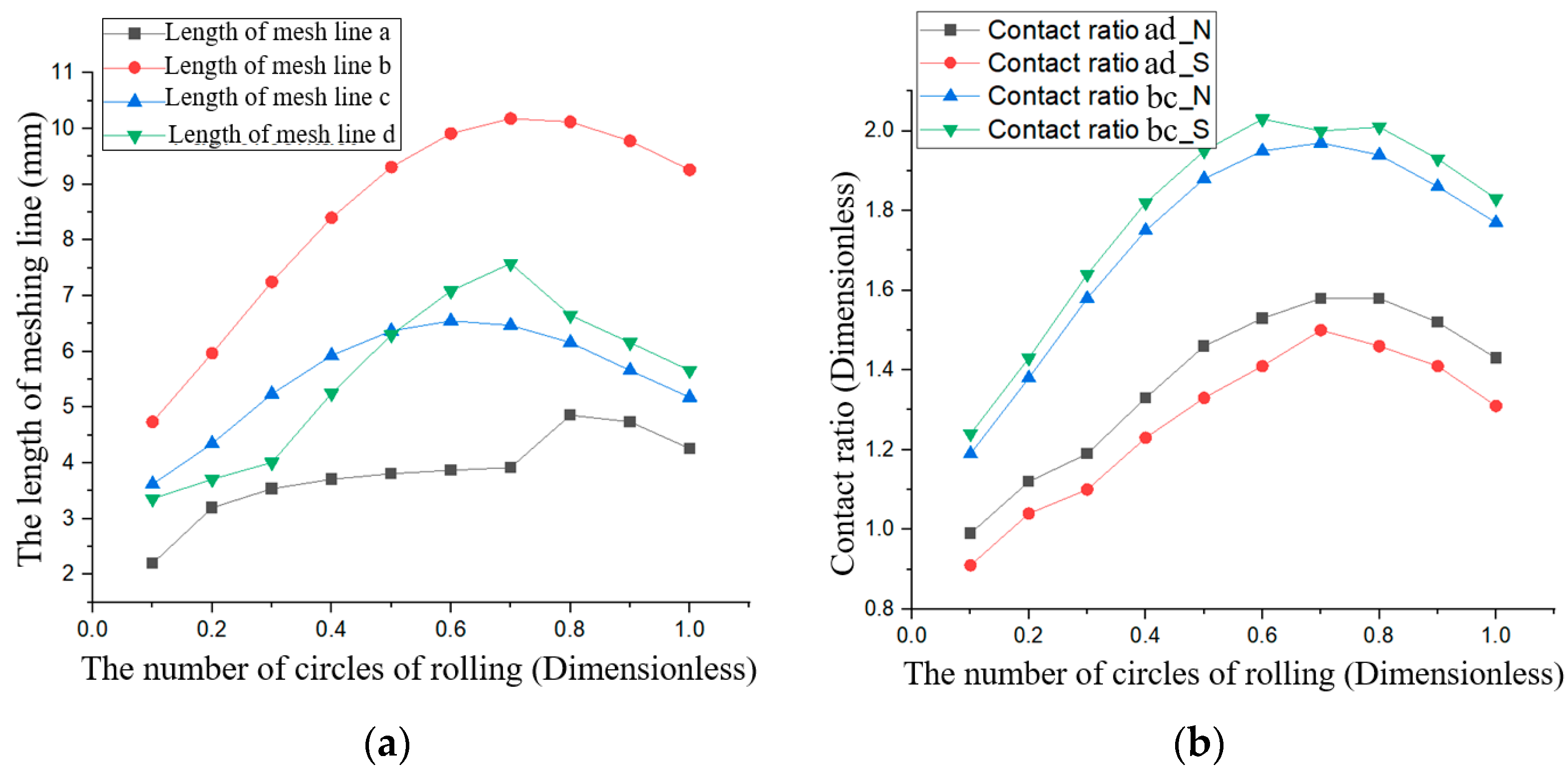
The contact ratio [32] of the VIIVC-CTF is the ratio of its meshing line to its tooth pitch of the non-circular gear with a cusp pitch curve. The tooth pitch is different from the rotation direction of the non-circular gear with a cusp pitch curve in this paper, that is, the contact ratio of the VIIVC-CTF designed in this paper is related to the rotation direction. The contact ratio of the VIIVC-CTF non-circular gear, the meshing line, and the contact ratios of clockwise and counterclockwise rotation are shown in Figure 7.
Figure 7 shows that when the driving gear rotates clockwise, the change law of meshing line length of the VIIVC-CTF ad and bc are as follows. With the increase in the rolling multiple, the length of the meshing line first increases and then decreases (that is, with the decrease in the rolling radius, the length of the meshing line first increases and then decreases). According to the definition of the contact ratio of a non-circular gear, the change law of the contact ratio of a non-circular gear of the cusp pitch curve is as follows. With the increase in rolling radius, the contact ratio first increases and then decreases. When the driving gear rotates counterclockwise, the change trend of the meshing line and contact ratio of the VIIVC-CTF is the same as that in the clockwise direction. The analysis shows that when the pitch curve designed in this paper rotates clockwise and when the rolling radii of tooth profile abcd are 0.85, 1.02, 1.21, and 1.16 mm, the corresponding meshing line is the largest.
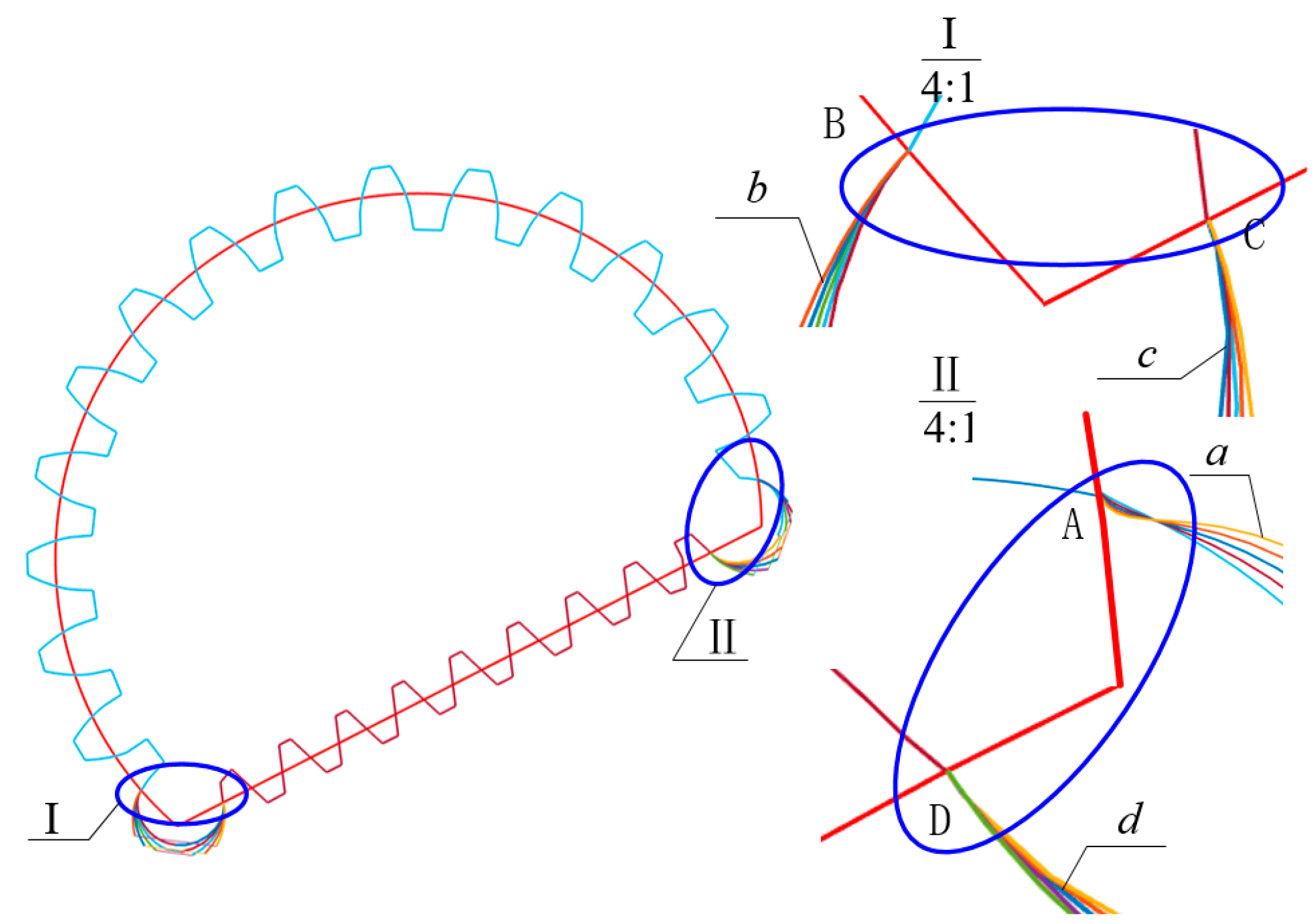
In Figure 8, different rolling radii corresponding to the incomplete cycloid tooth profiles are connected to the involute profile, however, there are unsmooth connections between the incomplete cycloid tooth profiles abcd and the corresponding involute at the connection of the pitch curve (that is, there are cusps of ABCD at the connection of tooth profile of the pitch curve), as shown in Figure 8. To ensure that there are no cusps at the junction of the involute and incomplete cycloid profile, this paper proposed VIIVC-CTF (i.e., it uses the ellipse to replace the rolling circle to design the incomplete cycloid profile). Finally, the smooth VIIVC-CTF is obtained.

4. Transmission Characteristics of VIIVC-CTF

4.1. Tooth Profile Characteristic of VIIVC-CTF

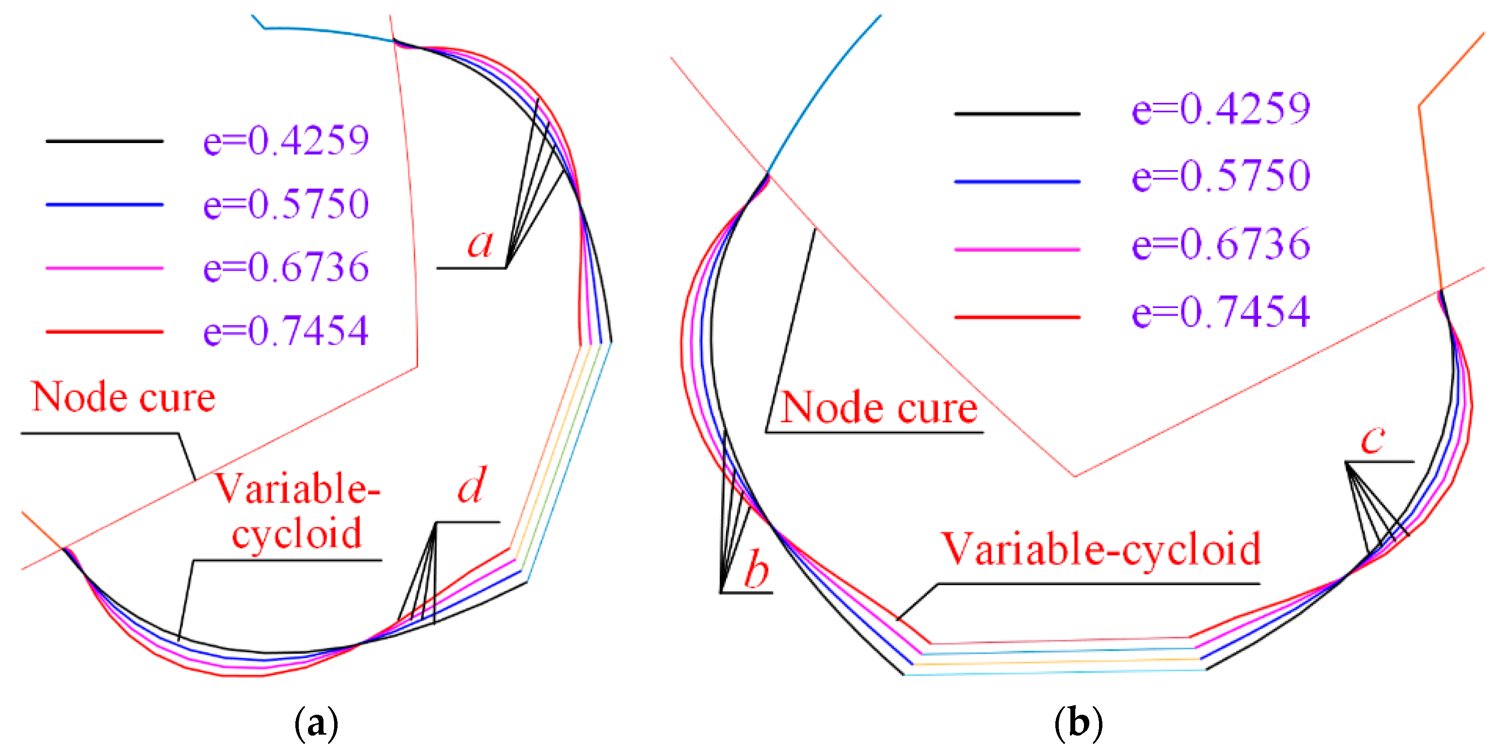
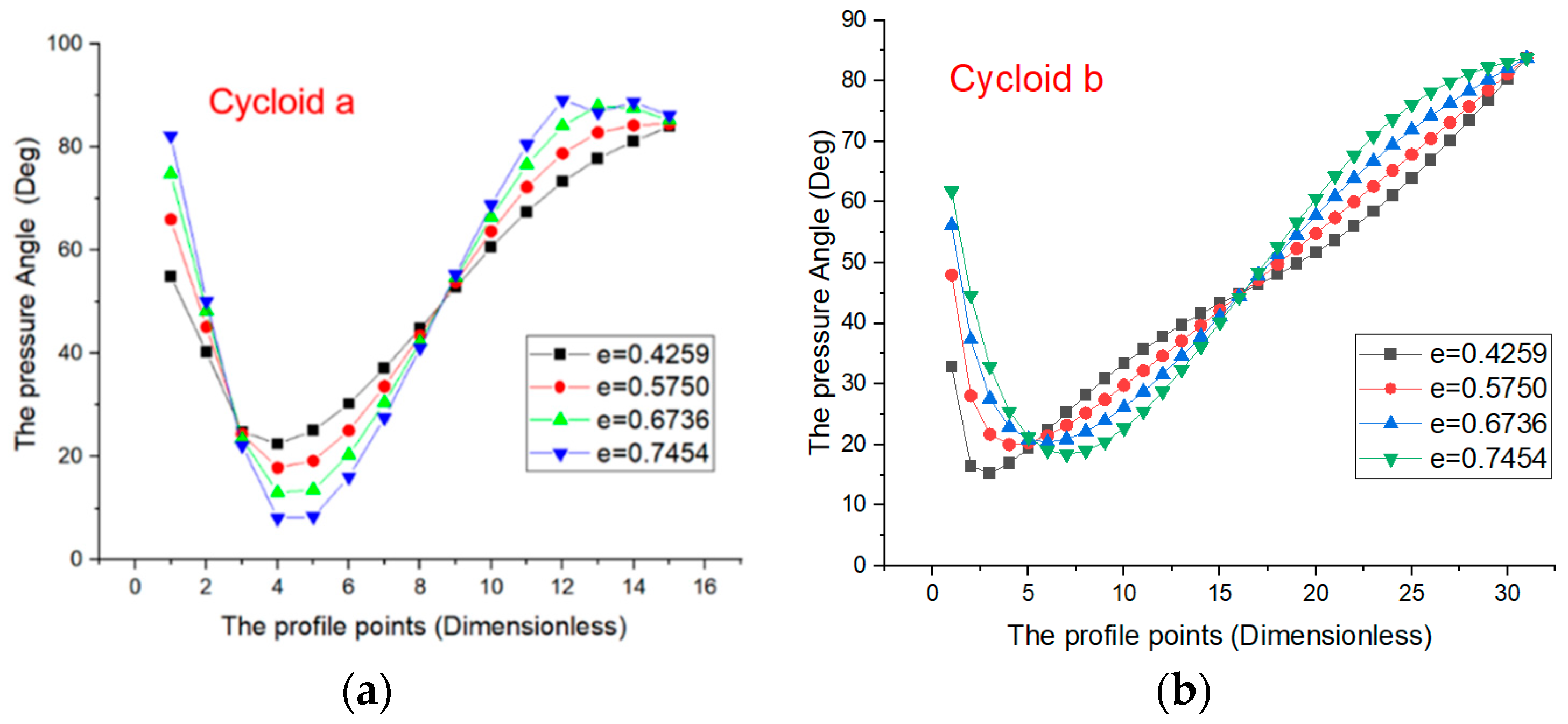
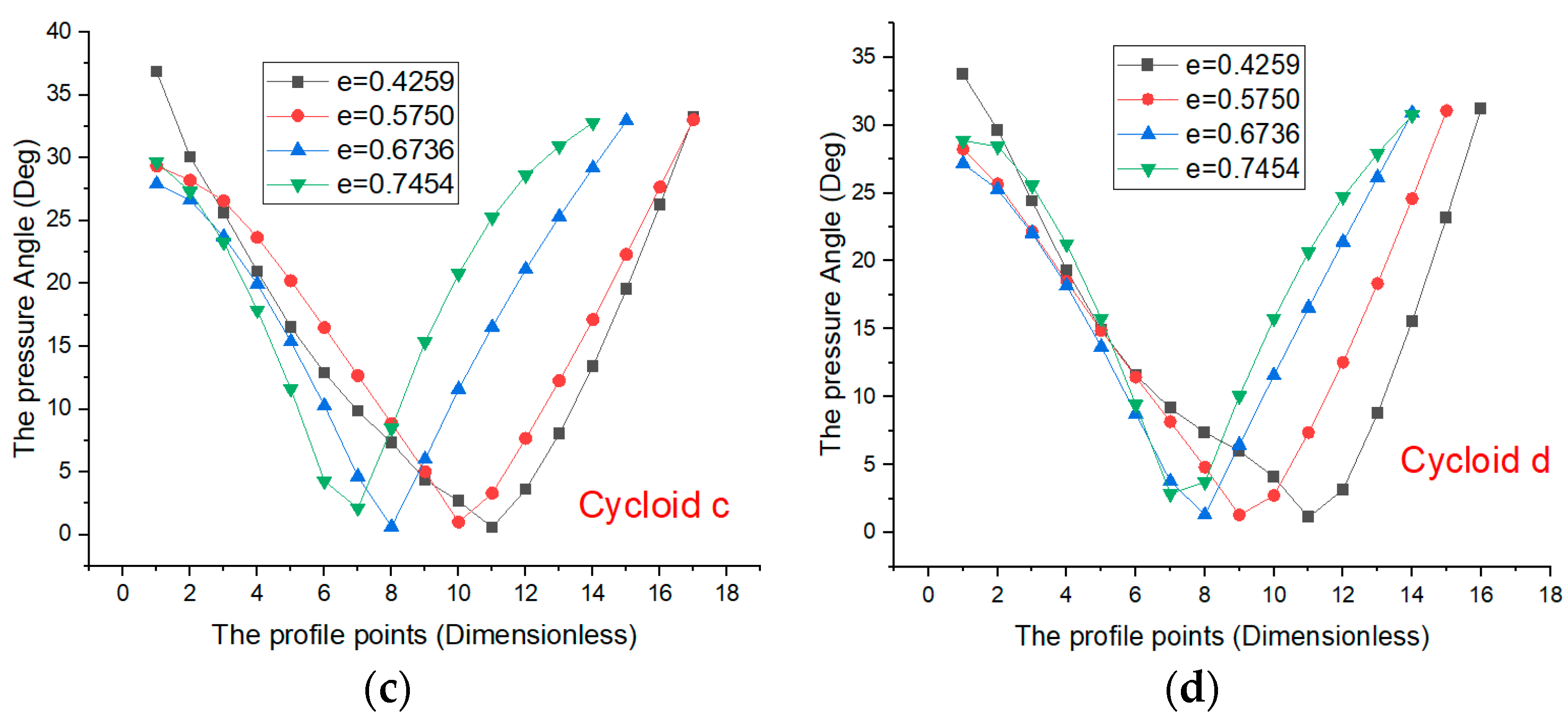
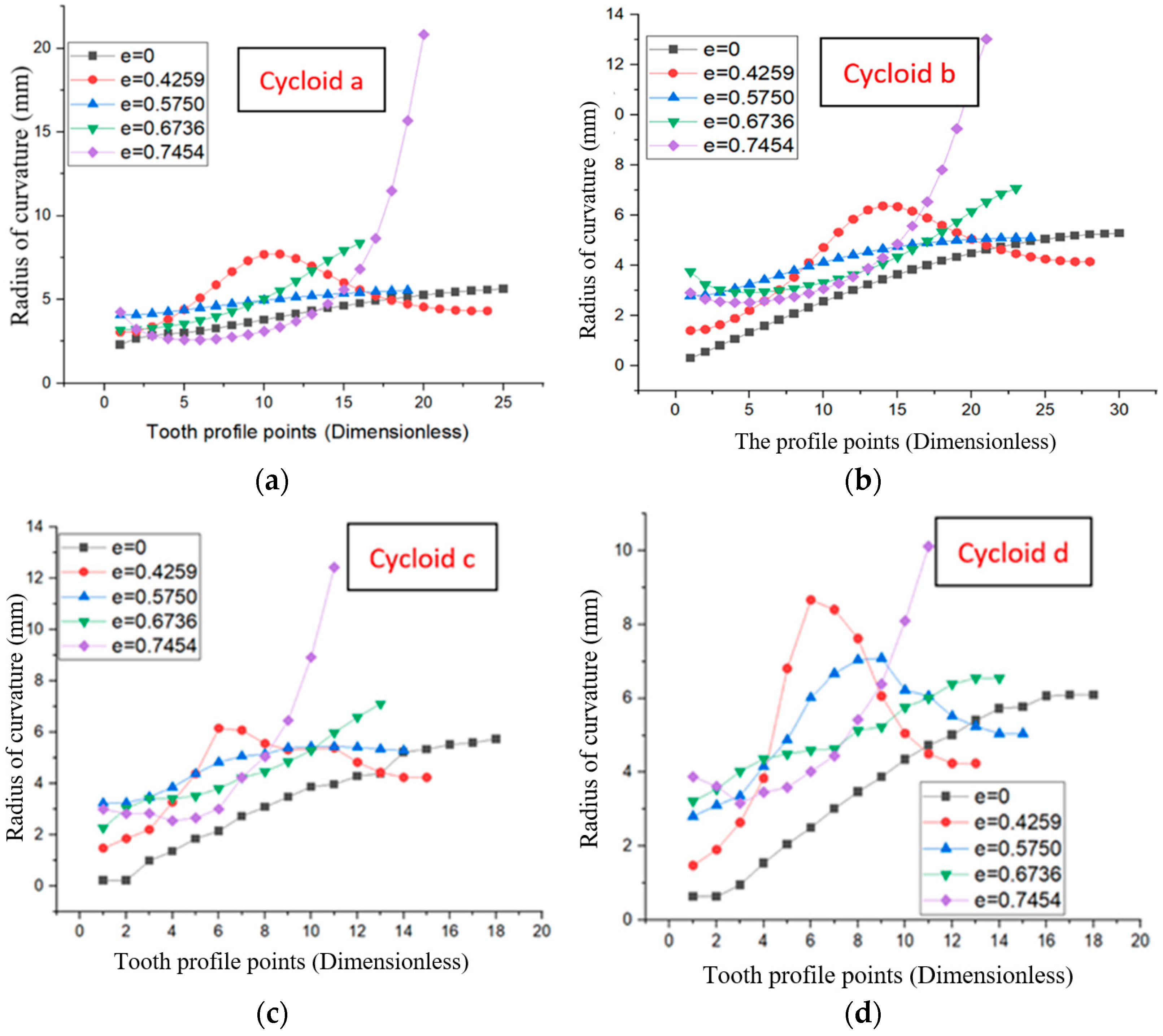
The above shows that although the tooth profile has the largest meshing line in the specified number of rolling cycles, the corresponding tooth profiles ad and bc cannot form a closed tooth profile, and the tooth profiles intersect, resulting in the incomplete design of tooth profile for pitch curve (that is, the correct transmission requirements of non-circular pitch curve cannot be realized). Considering the variation law of the contact ratio, pressure angle, and tooth profile shape, and designing a non-circular gear with a large contact ratio, the incomplete variable-cycloid tooth profiles abcd corresponding to the standard cycloid tooth profile of a non-circular gear with a cusp pitch curve designed in this research are both 0.5 (and the corresponding rolling radii are 1.32, 1.43, 1.46 and 1.62 mm). This is because the eccentricity of an ellipse rolling with a variable-cycloid profile can affect the pressure angle at the starting point of the variable-cycloid tooth profile. In this paper, based on the standard rolling, elliptic eccentricity is introduced to ensure the continuous connection between the variable-cycloid profile and the variable-involute profile at the connection. Figure 9, Figure 10 and Figure 11 show the curves of variable-cycloid tooth profile shape, pressure angle, and radius of curvature [34] with different elliptical eccentricities (e = 0.4259, 0.5750, 0.6736, 0.7454).
According to the pressure angle curve of the variable-cycloid tooth profile when rolling for 0.5 cycles in Figure 10, the minimum value of the pressure angle of the variable-cycloid tooth profiles a and b appears in advance with the increase in elliptical eccentricity, and the initial pressure angle of the variable-cycloid tooth profile at the pitch curve shows an increasing trend. The minimum pressure angle of the variable-cycloid tooth profiles c and d appears later with the increase in elliptical eccentricity, and the pressure angle of the variable-cycloid tooth profile at the beginning of the pitch curve shows a decreasing trend.
Figure 11 shows that the curvature radius of variable-cycloid tooth profiles ad and bc increase along the direction of the tooth profile, especially at the starting point of the pitch curve. The curve of the curvature radius of the variable-cycloid tooth profile under different elliptical eccentricities (the rolling radius is an ellipse) shows that when elliptical eccentricity is 0, it means a standard circle. With the increase in elliptical rolling eccentricity, the curvature radius of the cycloid tooth profile tends to be larger, but the change law is not evident, and the change of curvature radius fluctuates greatly, which is unfavorable to transmission, causing stress concentration on the tooth profile and affecting the service life and transmission accuracy of gear transmission.

4.2. The Meshing Line and Contact Ratio of VIIVC-CTF

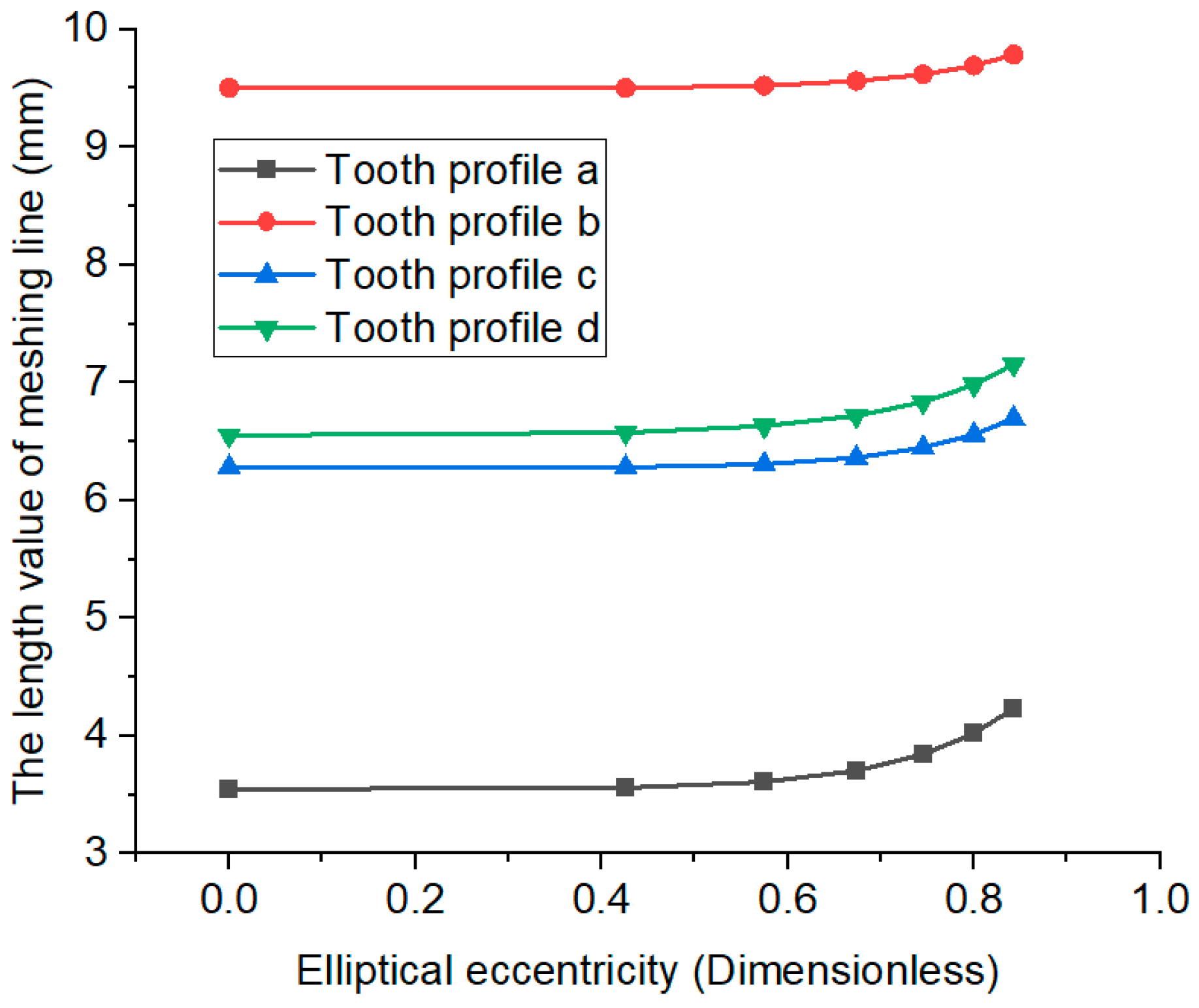
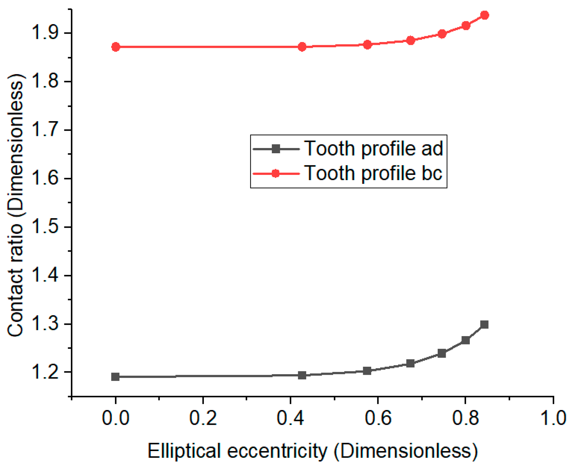
Contact ratio is an important characteristic for the feasibility of tooth profile design. It is the ratio of the length of the meshing line to the pitch [32]. The meshing line and contact ratio of anticlockwise rotation of incomplete variable-cycloid tooth profile corresponding to different elliptical eccentricities are shown in Figure 12 and Figure 13.
Figure 12 and Figure 13 show that the length of the meshing line and contact ratio of the incomplete variable-cycloid composite tooth profile increase with the increase in elliptical eccentricity. However, when the incomplete variable-cycloid composite tooth profile was designed, a rolling circle with large elliptical eccentricity cannot be used for tooth profile design in order to increase the meshing line and contact ratio only. The smooth connection with a variable-involute profile shape, pressure angle, and radius of curvature should be comprehensively considered.

5. Virtual Test of Non-Circular Gear Transmission Mechanism

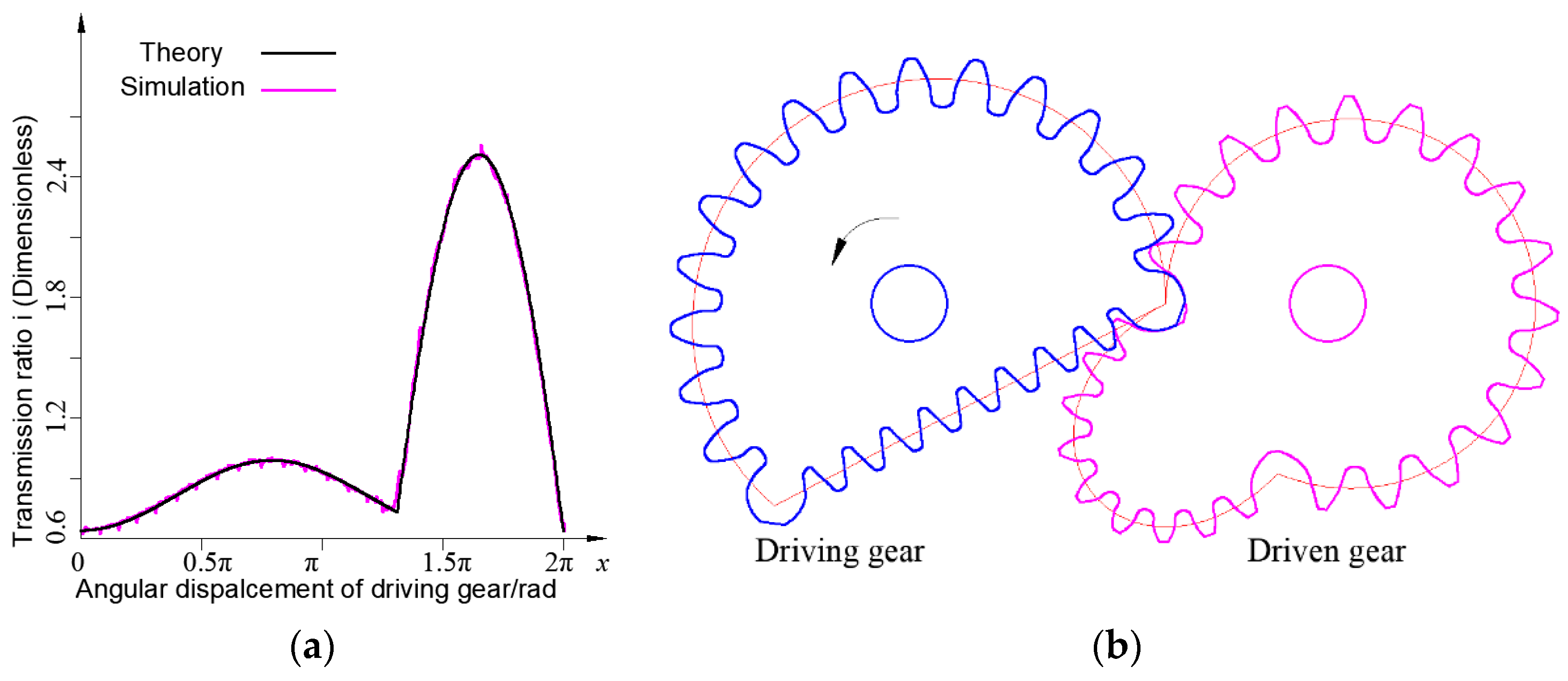
According to the theoretical transmission ratio curve shown in Figure 14a and center distance L = 55.38 mm, the driving gear tooth profile is designed based on the design software in Figure 5, and the driven gear tooth profile is designed based on the envelope method [32]. A non-circular gear transmission mechanism is designed, as shown in Figure 14b.
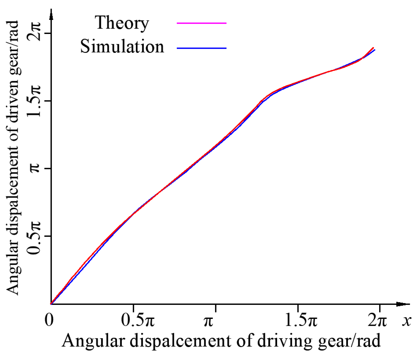
In this research, Adams software is used to conduct a virtual simulation on the non-circular gear transmission mechanism, and the angular displacement and transmission ratio curves of the transmission mechanism are obtained, as shown in Figure 15 and Figure 14a. Compared with the theoretical angular displacement and transmission ratio curve, the results of the theoretical transmission ratio and angular displacement curves are consistent with the simulation results of Adams software. The feasibility of the application of non-circular gears with cusp pitch curves of the VIIVC-CTF is verified.
The transmission ratio curve in Figure 14a shows that the theoretical and simulated transmission ratio curves are almost the same. The consistency of the transmission ratio curve verifies the feasibility of the design of the VIIVC-CTF.

6. Application and Experiment of VIIVC-CTF

6.1. Application of VIIVC-CTF in Seedling Pick-Up Mechanism with Non-Circular Gears

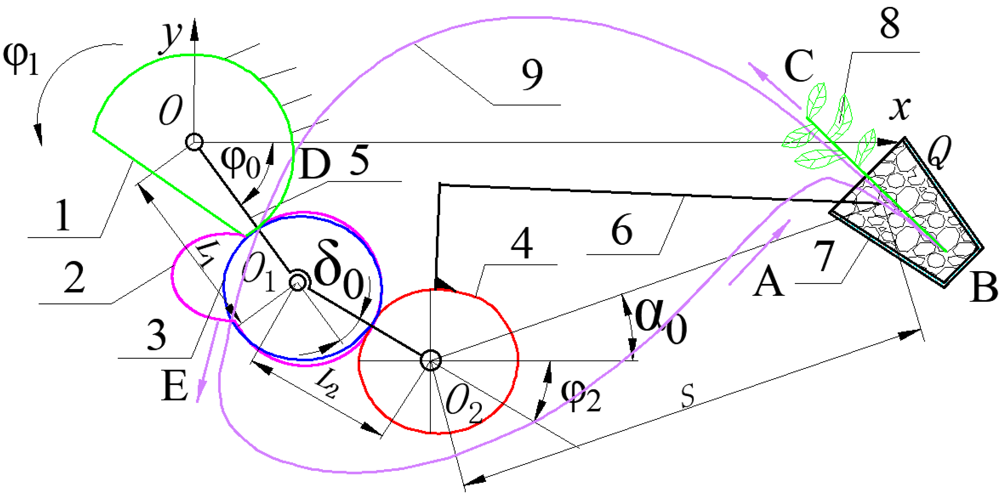
In this paper, the designed non-circular gear of the VIIVC-CTF is applied to the seedling pick-up mechanism of the planetary gear train to realize the action of grasping cavity plate seedlings and throwing seedlings. The schematic diagram of the seedling pick-up mechanism is shown in Figure 16. Through kinematic analysis of the seedling pick-up mechanism, the Q position equation of the seedling picking needle tip is obtained, as shown in Equation (15). The theoretical trajectory of the seedling pick-up mechanism can be obtained from Equation (15) and Figure 16. The non-circular gear of the VIIVC-CTF was manufactured based on wire-cutting technology. The simulation track and the experimental track of the seedling pick-up mechanism are obtained by using Adams software and the using high-speed camera technology, as shown in Figure 17. The seedling box is generally placed at 45° and a vertical entry and exit of the seedling needle are required to take the seedlings from the pot, which is more conducive to the success of seedling picking. Therefore, the angle of picking the seedlings is generally required to be about 45°. When pushing seedlings, the greater the seedling pushing angle (the seedlings are nearly vertical), the more conducive it is to the success of pushing seedlings, because the seedlings can be vertically dropped into the seedling planting mechanism by their gravity. The measurements of the seedling taking angle and seedling pushing angle are shown in Figure 18.
Non-circular gear 1 is fixed on the rack and meshes with non-circular gear 2, and non-circular gear 3 meshes with non-circular gear 4. Gears 2 and 3 are fixed to each other, and the seedling taking arm (6) and gear 4 are fixed to each other. The planet carrier rotates counterclockwise around the O point of the rotation center, driving gears 2 and 3 to rotate around the rotation center O1, and gear 4 rotates around the rotation center O2. In a cycle, the seedling picking arm along the seedling picking track (9) completes the seedling picking, holding, and pushing processes in tracks ABC, CD, and DE, respectively. The bowl (7) is generally placed at 45°.
The displacement equation of intermediate gear rotation center O1 is
{ x O 1 = L 1 cos ( ϕ 0 + ϕ 1 ) y O 1 = L 1 sin ( ϕ 0 + ϕ 1 )
The displacement equation of planetary gear rotation center O2 is
{ x O 2 = L 1 cos ( ϕ 0 + ϕ 1 ) + L 2 cos ( ϕ 0 + δ 0 + ϕ 1 ) y O 2 = L 1 sin ( ϕ 0 + ϕ 1 ) + L 2 sin ( ϕ 0 + δ 0 + ϕ 1 )
The displacement equation of the tip of the seedling arm Q is
{ x Q = L 1 cos ( ϕ 0 + ϕ 1 ) + L 2 cos ( ϕ 0 + δ 0 + ϕ 1 ) + S cos ( ϕ 0 + δ 0 + ϕ 1 + ϕ 2 + α 0 ) y Q = L 1 sin ( ϕ 0 + ϕ 1 ) + L 2 sin ( ϕ 0 + δ 0 + ϕ 1 ) + S sin ( ϕ 0 + δ 0 + ϕ 1 + ϕ 2 + α 0 )
Table 1 shows the interpretation of parameters required for kinematic modeling.
According to Figure 17d, the experimental track, simulation track, and theoretical calculation track of the seedling pick-up mechanism are consistent. Therefore, the feasibility of the application of the VIIVC-CTF non-circular gear in the seedling pick-up mechanism is verified.
As shown in Figure 18, the seedling picking and pushing angles of the seedling picking mechanism designed in this research are 44.7° and 70.2°, respectively. The angles of taking and pushing seedlings meet the requirements of taking and throwing seedlings.

6.2. Seedling Picking Experiment

Taking the pot seedling as the seedling picking object, the seedling pick-up mechanism was assembled to the test bed of the seedling pick-up mechanism for the seedling picking experiment. Figure 19 shows the seedling holding and pushing posture of the seedling pick-up mechanism.
According to Figure 19, the feasibility of the application of the VIIVC-CTF non-circular gear in the seedling pick-up mechanism of the planetary gear train is verified by the seedling picking experiment.

7. Discussion

According to the involute–cycloid composite tooth profile [32] and variable-involute and variable-cycloid composite tooth profile (VIVC-CTF) [33] proposed earlier, the problem of undercutting involute tooth profile of a non-circular gear with a small curvature radius pitch curve was solved. It is feasible to apply the variable-involute and incomplete variable-cycloid composite tooth profile (VIIVC-CTF) proposed in this paper to the design of non-circular gears with cusp pitch curves. This kind of VIIVC-CTF can be applied to the transmission mechanism of a special transmission ratio curve, such as the seedling picking mechanism of the transplanting machine listed in this paper to achieve a special seedling picking track, and the design of a non-circular gear with a cusp pitch curve is a difficult problem in gear design. In the later stage, this research group will carry out the design and research of space gears with such combined tooth profiles.

8. Conclusions

(1) A design method of a non-circular gear with a cusp pitch curve is proposed, and the design platform of a non-circular gear with a cusp pitch curve is developed. The driving gear of a non-circular gear with a cusp pitch curve is designed by using the new VIIVC-CTF, and the driven non-circular gear is designed based on the envelope method.
(2) The relationship between the variation and curvature of the tooth profile is discussed. The mathematical tooth profile model of the driving gear and the model of the driven non-circular gear are constructed by using the normal method and envelope method.
(3) Non-circular driving and driven gears are manufactured by using the wire-cutting method. A virtual test of a non-circular gear transmission mechanism is carried out. By comparing the theoretical and virtual test values of the transmission ratio curve, the transmission feasibility of the VIIVC-CTF is proven.
(4) By comparing the seedling picking trajectory of the seedling pick-up mechanism, the theoretical, simulation, and experimental curves are consistent, which verifies the feasibility of the design method of the VIIVC-CTF for a non-circular gear with a cusp pitch curve. Through the seedling picking experiment of the seedling pick-up mechanism, the feasibility of the application of the VIIVC-CTF in the seedling pick-up mechanism is verified.

Author Contributions

The authors’ contributions are as follows: G.-H.Y. was in charge of the whole trial; J.-G.L. wrote the manuscript; Z.-P.T. and X.Z. derived formulas and verified results; H.-L.Z. conducted the simulation and experiment. All authors have read and agreed to the published version of the manuscript.

Funding

The authors would like to thank the National Natural Science Foundation of China (Grant Nos. 52075497 and 32071909), the Key Research and Development Projects in Zhejiang Province (Grant No. 2022C02048), and the Fujian Natural Science Foundation (No. 2021J011133). Furthermore, this research was supported by the Open Project Program of the Key Laboratory for Agricultural Machinery Intelligent Control and Manufacturing of Fujian Education Institutions (No. AMICM202101).

Institutional Review Board Statement

Not applicable.

Informed Consent Statement

Not applicable.

Data Availability Statement

Not applicable.

Conflicts of Interest

The authors declare no conflict of interest.

References

  1. Wang, J.; Liu, Q.Q.; Yang, S.R.; Li, H.X.; Qang, Z.L.; Li, Q. Geometric Design and Analysis of Novel Asymmetrical Rotors for Roots Vacuum Pumps. J. Mech. Des. 2020, 142, 1–6. [Google Scholar] [CrossRef]
  2. Choi, T.H.; Kim, M.S.; Lee, G.S.; Jung, S.Y.; Bae, J.H.; Kim, C.B. Design of Rotor for Internal Gear Pump Using Cycloid and Circular-Arc Curves. J. Mech. Des. 2012, 134, 011005. [Google Scholar] [CrossRef]
  3. Chen, Q.; Xu, F.; Liu, P.; Fan, H. Research on Fractal Model of Normal Contact Stiffness between two spheroidal joint surfaces considering friction factor. Tribol. Int. 2016, 97, 253–264. [Google Scholar] [CrossRef]
  4. He, S.X.; He, Y.B.; Chen, Y.C.; Dai, Q.S.; Liu, X. Research on Contact Stiffness of Cycloid-pin Gear based on Monte Carlo Method. J. Mech. Transm. 2021, 45, 28–32. [Google Scholar]
  5. Chung, W.J.; Park, J.H.; Yoo, H.G.; Park, Y.J.; Kim, S.C.; Sohn, J.; Lee, G.H. Improved analytical model for calculating mesh stiffness and transmission error of helical gears considering trochoidal root profile. Mech. Mach. Theory 2021, 163, 104386. [Google Scholar] [CrossRef]
  6. Yang, J.; Lin, T.J.; He, Z.Y.; Chen, M. Novel Calculation method for Dynamic Excitation of modified double-helical gear transmission. Mech. Mach. Theory 2022, 167, 104467. [Google Scholar] [CrossRef]
  7. Sun, Z.; Chen, S.Y.; Hu, Z.H.; Tao, X. Improved Mesh Stiffness Calculation model of comprehensive modification gears considering actual manufacturing. Mech. Mach. Theory 2022, 167, 104470. [Google Scholar] [CrossRef]
  8. Choi, C.H.; Ahn, H.J.; Park, Y.J.; Lee, G.H.; Kim, S.C. Influence of Gear tooth Addendum and Dedendum on the helical gear optimization considering mass, efficiency and transmission error. Mech. Mach. Theory 2021, 166, 104476. [Google Scholar] [CrossRef]
  9. Benaïcha, Y.; Perret-Liaudet, J.; Beley, J.D.; Rigaud, E.; Thouverez, F. On a Flexible Multibody Modelling approach using FE-based contact formulation for describing gear transmission error. Mech. Mach. Theory 2022, 167, 104505. [Google Scholar] [CrossRef]
  10. Korta, J.A.; Mundo, D. Multi-objective Micro-geometry Optimization of gear tooth supported by response surface methodology. Mech. Mach. Theory 2017, 109, 278–295. [Google Scholar] [CrossRef]
  11. Kim, S.C.; Moon, S.G.; Sohn, J.H.; Park, Y.J.; Choi, C.H.; Lee, G.H. Macro Geometry Optimization of a Helical Gear pair for mass, efficiency, and transmission error. Mech. Mach. Theory 2020, 144, 103634. [Google Scholar] [CrossRef]
  12. Zheng, F.Y.; Guo, X.D.; Zhang, M.D. Non-uniform flank rolling measurement for shaped noncircular gears. Measurement 2018, 116, 207–215. [Google Scholar] [CrossRef]
  13. Zheng, F.Y.; Hua, L.; Han, X.H. The mathematical model and mechanical properties of variable center distance gears based on screw theory. Mech. Mach. Theory 2016, 101, 116–139. [Google Scholar] [CrossRef]
  14. Lin, C.; Wang, Y.T. Principle and Design of Noncircular Pin-Cycloid Gear Transmission. J. Northeast. Univ. (Nat. Sci.) 2014, 35, 1190–1194. [Google Scholar]
  15. Hou, Y.J.; Lin, C. Kinematic Analysis and Experimental Verifcation of an oval noncircular bevel gears with rotational and axial translational motions. J. Braz. Soc. Mech. Sci. Eng. 2020, 42, 60. [Google Scholar] [CrossRef]
  16. Vivet, M.; Tamarozzi, T.; Desmet, W.; Mundo, D. On the Modelling of gear alignment errors in the tooth contact analysis of spiral bevel gears. Mech. Mach. Theory 2021, 155, 104065. [Google Scholar] [CrossRef]
  17. Dooner, D.B.; Vivet, M.; Mundo, D. Deproximating Tredgold’s Approximation. Mech. Mach. Theory 2016, 102, 36–54. [Google Scholar] [CrossRef]
  18. Litvin, F.L.; Gonzalez-Perez, I.; Yukishima, K.; Fuentes, A.; Hayasaka, K. Design, Simulation of Meshing, and contact stresses for an improved worm gear drive. Mech. Mach. Theory 2007, 42, 940–959. [Google Scholar] [CrossRef]
  19. Liu, P.; Zhao, H.; Huang, K.; Chen, Q.; Xiong, Y.T. Research on Normal Contact Stiffness of Micro-segments Gear Based on Improved Fractal Model. J. Mech. Eng. 2018, 54, 114–122. [Google Scholar] [CrossRef]
  20. Xiong, Y.S.; Han, G.Z.; Huang, K.; Zhao, H. Research on the Nonlinear Dynamics of Micro-segment Gear System with Time-Varying Friction Coefficient. J. Mech. Eng. 2021, 57, 113–127. [Google Scholar]
  21. Chen, Y.Z.; Zhu, A.S.; Lü, Y.L. Study on the Meshing Characteristic of Parallel Axis Line Gear. J. Mech. Transm. 2018, 42, 1–6. [Google Scholar]
  22. Krawiec, P.; Grzelka, M.; Kroczak, J.; Domek, G.; Kołodziej, A. A proposal of measurement methodology and assessment of manufacturing methods of nontypical cog belt pulleys. Measurement 2019, 132, 182–190. [Google Scholar] [CrossRef]
  23. Krawiec, P.; Domek, G.; Warguła, Ł.; Waluś, K. The application of the optical system ATOS II for rapid prototyping methods of non-classical models of cogbelt pulleys. In Proceedings of the MATEC Web of Conferences, Sklené Teplice, Slovak Republic, 5–8 September 2017; p. 01010. [Google Scholar]
  24. Medvecká-Beňová, S. Designing pitch curves of non-circular gears. Sci. J. Sil. Univ. Technol. 2018, 99, 105–114. [Google Scholar] [CrossRef]
  25. Maláková, S.; Urbanský, M.; Fedorko, G.; Molnár, V.; Sivak, S. Design of Geometrical Parameters and Kinematical Characteristics of a Non-circular Gear Transmission for Given Parameters. Appl. Sci. 2021, 11, 1000. [Google Scholar] [CrossRef]
  26. Cristescu, A.; Cristescu, B.; Andrei, L. Finite element analysis of multispeed noncircular gears. Appl. Mech. Mater. 2015, 808, 246–251. [Google Scholar]
  27. Niculescu, M.; Andrei, L. Using noncircular gears for the unloading door kinematics modification. In Proceedings of the MATEC Web of Conferences, Iasi, Romania, 24–27 May 2017; Volume 112, p. 6013. [Google Scholar]
  28. Nezir, E.; Nihat, Y.; Fatih, E.; Bahadır, K.; Burak, Ş. Non-circular gear design, elliptical gears as example. In Proceedings of the Ejons VI–International Conference on Mathematics Engineering Natural & Medical Sciences, Adana, Turkey, 14–16 November 2019; pp. 624–641. [Google Scholar]
  29. Yu, G.H.; Yu, J.P.; Tong, J.H.; Ye, B.L.; Zheng, S.Y. Design a Conjugate Concave-convex Non-circular Gear Mechanism. China Mech. Eng. 2016, 27, 2155–2159, 2165. [Google Scholar]
  30. Yu, G.H.; Yu, T.F.; Ye, B.L. Design of a Rotary Plug Seedling Pick-up Mechanism. J. Mech. Eng. 2015, 51, 67–76. [Google Scholar] [CrossRef] [Green Version]
  31. Yu, G.H.; Tong, Z.P.; Sun, L. Novel Gear Transmission Mechanism with Twice Unequal Amplitude transmission Ratio. J. Mech. Des. 2019, 141, 092304. [Google Scholar] [CrossRef]
  32. Liu, J.G.; Tong, Z.P.; Yu, G.H.; Zhao, X.; Zhou, H.L. Design of a Noncircular gear Mechanism with Twice Unequal Amplitude Transmission Ratio. J. Mech. Robot. 2022, 14, 054501. [Google Scholar] [CrossRef]
  33. Liu, J.G.; Tong, Z.P.; Yu, G.H.; Zhao, X.; Zhou, H.L. Non-circular gear transmission mechanism with Variable-Involute and Variable-Cycloid composite tooth profile. J. Mech. Sci. Technol. 2022, 36, 2445–2459. [Google Scholar] [CrossRef]
  34. Wu, X.T. Gear Meshing Principle; Machine Press: Beijing, China, 2009. [Google Scholar]
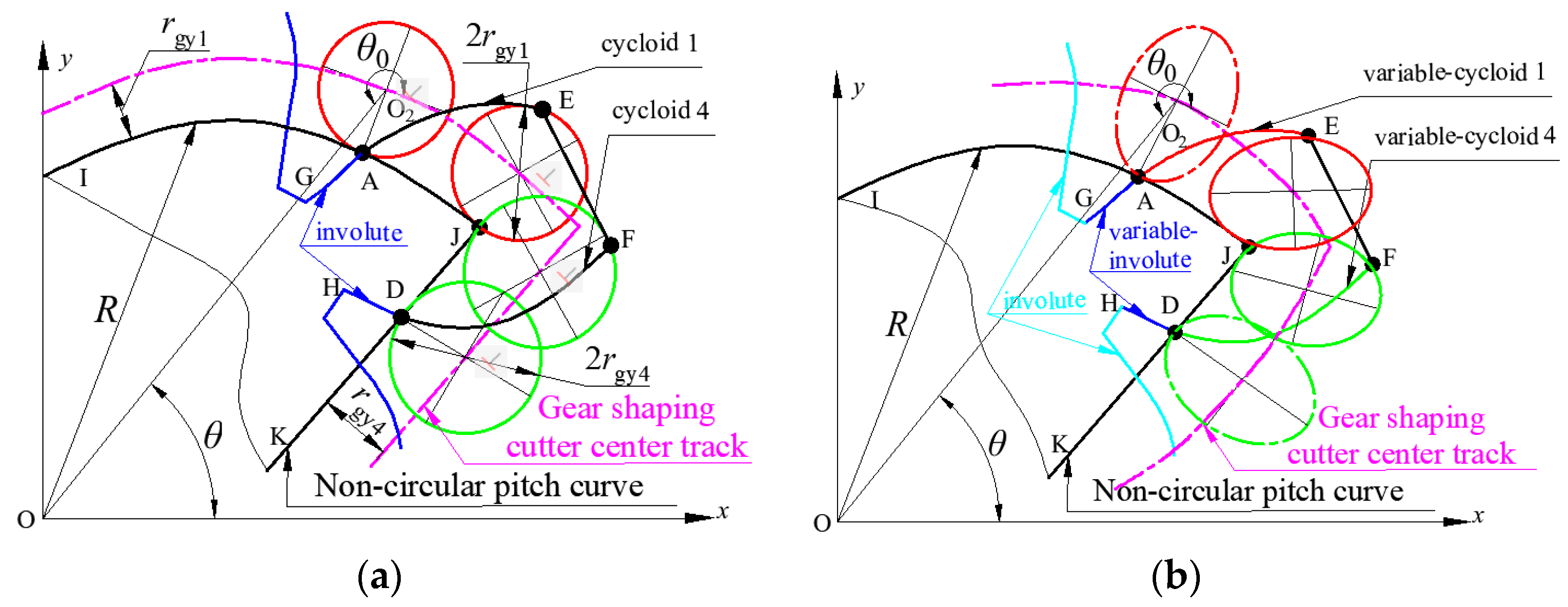
Figure 1. Schematic diagram of the VIIVC-CTF at cusp pitch curve: (a) involute and incomplete cycloid tooth profile; (b) VIIVC-CTF.
Machines 10 00985 g001
Figure 2. Non-circular pitch curve with cusp.
Machines 10 00985 g002
Figure 3. Schematic diagram of non-circular incomplete variable-involute tooth profile.
Machines 10 00985 g003
Figure 4. Flow chart of software development for designing non-circular gears with cusp pitch curves.
Machines 10 00985 g004
Figure 5. Software generation diagram of cusp pitch curve’s tooth profile.
Machines 10 00985 g005
Figure 6. Variation of tooth profiles with rolling radius: (a) tooth profile of bc changes with rolling radius; (b) tooth profile of ad changes with rolling radius; (c) relationship between rolling radius and number of rolling cycles.
Machines 10 00985 g006
Figure 7. Length of meshing line and contact ratio curve with different rolling radii: (a) the number of rolling cycles corresponds to the length of the meshing line of the variable-cycloid tooth profile; (b) the number of rolling cycles corresponds to the contact ratio of the composite tooth profile (clockwise/counterclockwise).
Machines 10 00985 g007
Figure 8. Driving gear and its partially enlarged view.
Machines 10 00985 g008
Figure 9. Tooth profile shapes with different elliptical eccentricities: (a) different elliptical eccentricities of tooth profile ad; (b) different elliptical eccentricities of tooth profile bc.
Machines 10 00985 g009
Figure 10. Pressure angle under different elliptical eccentricities (0.5 rolling cycles): (a) pressure angle under different elliptical eccentricities of cycloid a; (b) pressure angle under different elliptical eccentricities of cycloid b; (c) pressure angle under different elliptical eccentricities of cycloid c; (d) pressure angle under different elliptical eccentricities of cycloid d.
Machines 10 00985 g010aMachines 10 00985 g010b
Figure 11. Curvature radius of tooth profile of pendulum line with different elliptical eccentricities (0.5 rolling cycles): (a) curvature radius of tooth profile of pendulum line with different elliptical eccentricities of cycloid a; (b) curvature radius of tooth profile of pendulum line with different elliptical eccentricities of cycloid b; (c) curvature radius of tooth profile of pendulum line with different elliptical eccentricities of cycloid c; (d) curvature radius of tooth profile of pendulum line with different elliptical eccentricities of cycloid d.
Machines 10 00985 g011
Figure 12. The length value of the meshing line of different elliptical eccentricities.
Machines 10 00985 g012
Figure 13. The contact ratio of different elliptical eccentricities.
Machines 10 00985 g013
Figure 14. Transmission ratio curve and Non-circular gear transmission mechanism: (a) Transmission ratio curve of theory and simulation; (b) Non-circular gear transmission mechanism.
Machines 10 00985 g014
Figure 15. Angular displacement curve for theory and simulation.
Machines 10 00985 g015
Figure 16. Schematic diagram of the seedling pick-up mechanism: 1. sun gear; 2. intermediate gear 1; 3. intermediate gear 2; 4. planetary gear; 5. planet carrier; 6. seedling arm; 7. bowl plate; 8. bowl seedling; 9. seedling picking track.
Machines 10 00985 g016
Figure 17. Application of the seedling pick-up mechanism: (a) assembly diagram of the seedling pick-up mechanism; (b) experimental track of the seedling pick-up mechanism; (c) virtual experiment of the seedling pick-up mechanism; (d) comparison of the seedling picking tracks of the seedling pick-up mechanism.
Machines 10 00985 g017aMachines 10 00985 g017b
Figure 18. Measurement of the seedling taking and pushing angles: (a) seedling picking angle; (b) seedling pushing angle.
Machines 10 00985 g018
Figure 19. Seedling picking experiment: (a) seedling picking posture; (b) seedling pushing posture.
Machines 10 00985 g019
Table 1. Parameter description of the seedling pick-up mechanism.
SymbolMeaningSymbolMeaning
SDistance from the rotation center of the planet gear to the tip of the seedling needleφ0Angle of rotation of the second-stage planetary carrier relative to the first-stage planetary carrier
L1, L2Distance of the center of the first and second gear transmissionα0Installation position of the seedling picking arm relative to the planet carrier
φ1Angular displacement of planet gear relative to planet carrierδ0Initial installation position of the planet carrier
φ2Angle of the planet carrier
Publisher’s Note: MDPI stays neutral with regard to jurisdictional claims in published maps and institutional affiliations.