Article

Machining Quality Prediction of Marine Diesel Engine Block Based on Error Transmission Network

1
School of Mechanical Engineering, Jiangsu University of Science and Technology, Zhenjiang 212000, China
2
Department of Control Engineering, Rocket Engineering University, Xi’an 710025, China
*
Author to whom correspondence should be addressed.
These authors contributed equally to this work.
Machines 2022, 10(11), 1081; https://doi.org/10.3390/machines10111081
Submission received: 8 October 2022 / Revised: 11 November 2022 / Accepted: 14 November 2022 / Published: 16 November 2022
(This article belongs to the Special Issue Advances in Diagnostics and Prognostics in the Era of Industry 4.0)

Abstract

:
In view of the high precision requirement of the marine diesel engine body and the difficulty of quality control, a quality prediction method of the body, based on a process error transfer network, is proposed. First, according to the processing information of the body, the network nodes and edges are abstracted to establish the process error transfer network of the body. Then, the key quality control points and key quality features of the diesel engine body are determined by the PageRank and node degree. The key quality features obtained from the network analysis are taken as the output, and the corresponding process errors and process parameters are taken as the input. Finally, the quality prediction model of the body is established based on SVR algorithm, and the C, g parameters of SVR algorithm are optimized by the K-fold cross-validation method and grid search method to improve the prediction accuracy of the body processing quality.

1. Introduction

The processing procedures of the diesel engine body are complex, and the formation of its final quality often needs to go through multiple procedures [1]. The factors affecting the quality of the body during the processing process can be divided into two categories. One is the static factors generated before the process processing, such as the quality of the output of the previous process; the other is the dynamic factors received in the process, such as machine tools, tools, fixtures, and errors of the operator. Based on the effect of these two types of influencing factors, the machining error of the body is transferred between multiple processes and forms the final machining quality of the body. Therefore, the analysis of each process in the machining sequence of the machine body can truly achieve comprehensive control of the machine body quality.
Currently, prediction techniques are widely used in the pre-control of the part quality [2]. LU [3] adopted the regression orthogonal design method to obtain a regression prediction model of the grinding process parameters and product reliability from the collected relevant experimental data. Similarly, S. Selvakumar et al. [4] used an orthogonal design-of-experiment approach to determine the clamping layout scheme and developed a prediction model based on BP neural network between the element position and machining deformation. Mo et al. [5] predicted the warpage and sink marks of the injection molded products based on the RBF neural network algorithm. Hertlein et al. [6] constructed a multi-factor hybrid Bayesian network to predict the machining quality based on the laser additive manufacturing process and investigated the relationship between the process parameters and product quality. Li et al. [7] used historical data to construct the mapping relationship between the process factors and quality output in the multi-process manufacturing of complex equipment to predict the pre-tightening force of the shaft end thread. Huang et al. [8] established a support vector machine-based cylindrical longitudinal grinding surface roughness prediction model to solve the problem that there are many influencing factors in grinding processing, and it is difficult to realize automatic processing. Ashtiani et al. [9] established a neural network model based on a feedforward propagation learning algorithm for predicting the thermal deformation behavior of the alloy and obtained better prediction results. Chen [10] summarized the methods and applications for the workpiece surface profile and roughness prediction using an RBF neural network model trained with adaptively tuned parameters to predict the surface profile shape of the turned machining. E. Portillo [11] used a neural network to predict the degradation behavior of EDM wire, according to the information of the workpiece and its processing technology. Tirkel [12] used machine learning algorithms to establish a wafer processing cycle prediction model, which improved the efficiency of product manufacturing and supply. Zheng W et al. [13] studied the influence of ultrasound-assisted grinding process parameters on the three-dimensional surface morphology of aluminum-based silicon carbide grinding. Zajac J et al. [14] conducted high-speed milling tests on thin-walled components and summarized the measures to reduce deformation during milling. Duplak Jan et al. [15] conducted experiments based on three materials by surface roughness simulation method and direct contact measurement method, thus verifying the technical requirements to ensure the production of dimensional and quality shapes.
However, most of the quality prediction models established by the above-mentioned research institutes are based on the input of processing parameters of the parts, without considering the error transmission relationships during the machining process of the parts. Once the state of the processing system changes, the quality prediction models established are likely to fail. To this end, the machining features and machining elements in the diesel engine body machining process were used as nodes in this paper. Then, the machining error transmission network of the body was constructed based on the transmission relationship between each node. Then, the machining quality prediction model of the body was established using the parameter optimized SVR algorithm by incorporating the input of machining element errors and the input of the former quality characteristics based on the process parameters. Finally, the quality prediction model developed by the proposed method can adapt to different process system states and provide more accurate prediction results. Likewise, it provides more intuitive guidance for the quality control of diesel engine bodies under multi-processes and multi-stages.
The main contributions of the proposed method are:
  • Based on the transfer relationship between the processing features of the diesel engine body and between the processing features and processing elements, the processing error transfer network was established.
  • Based on the PageRank algorithm and the calculation of the node degree value, the key quality control points and key quality features in the diesel engine body machining process were determined.
  • Based on the error transfer relationship, the SVR algorithm parameters were optimized using a combination of the K-fold cross-validation method and the grid search method.
The rest of this article is organized as follows. The details of the proposed prediction scheme for the collective machining error transfer network for diesel engines are presented in Section 2. After analyzing the influence of the processes on the machining quality during the diesel engine machining process, Section 3 presents the creation and analysis of the machining error transfer network for the diesel engine body. Section 4 describes the content of our experiments and provides an overview of the prediction model established for the machining quality of diesel engine bodies. Among others, the necessary comparisons and validations are also given. Specific conclusions are drawn in Section 5.

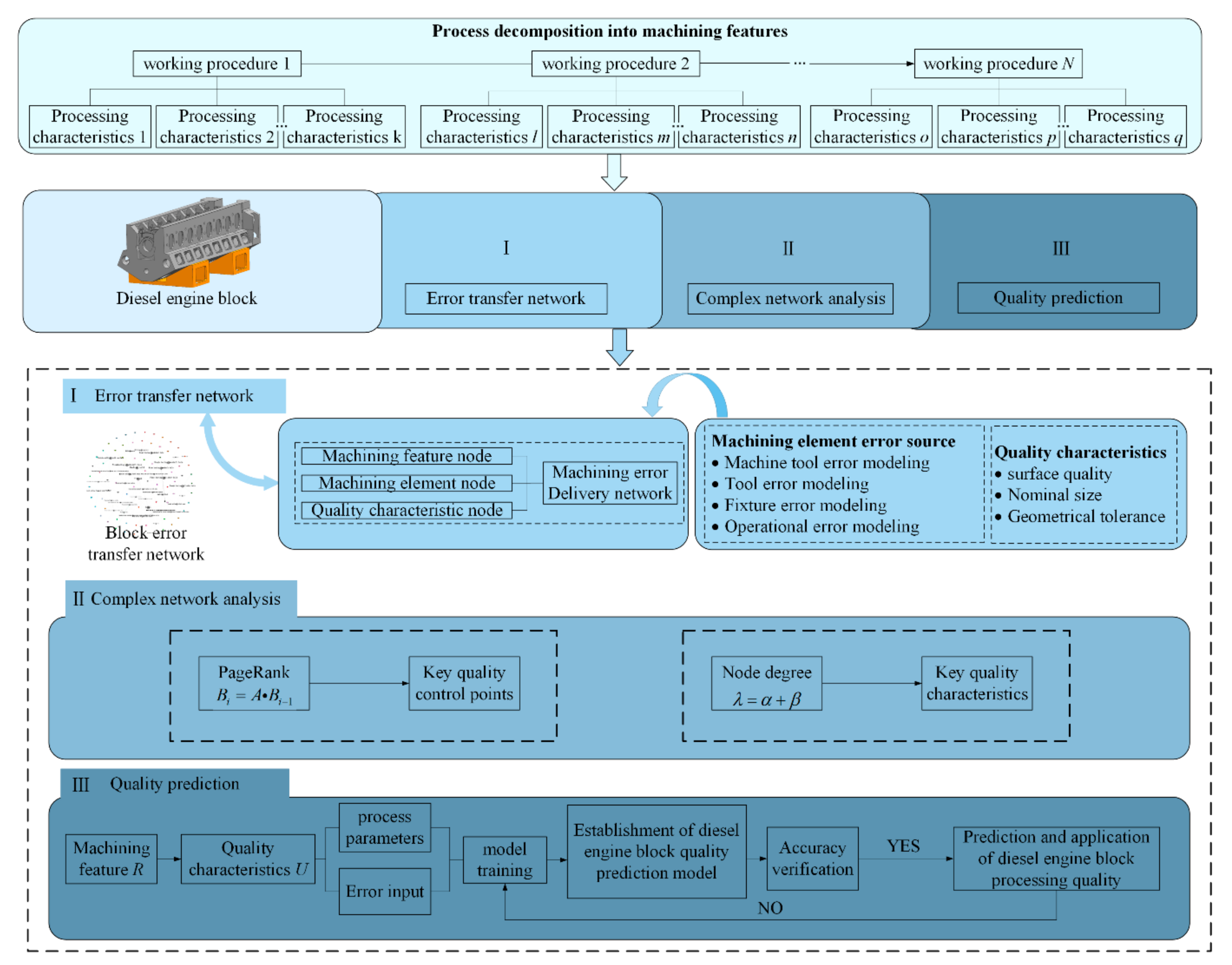
2. Establishment of Machining Error Transmission Network of Diesel Engine Block and Analysis of Quality Prediction Scheme

The diesel engine body is the basic part of diesel engine—its purpose is to assemble some shafts, bushings, bearings, and other related parts of the diesel engine. Then, make it maintain the correct mutual position relationship to complete the specified movement. The machining quality of the diesel engine body is an important guarantee of the final quality of the marine diesel engine. Its quality is an important indicator for measuring the assembly performance and operation reliability of a marine diesel engine.
However, the structure of the diesel engine body is complex, and the sources of influence on the quality characteristics corresponding to each process include not only the errors of the machine tool, tool, and fixture, but also the machining quality of the previous process. Therefore, for the machining of the diesel engine body, its machining quality is the result of the accumulation of multiple error streams transmitted during its process. The overall diesel engine body machining error transfer network modeling and quality prediction scheme is shown in Figure 1. First, the overall scheme decomposes the N machining processes of the diesel engine body, and each process is decomposed into multiple machining features. Then, the machining quality prediction of the diesel engine body is divided into three parts, which are the machining error transfer network of the diesel engine body, the complex network analysis, and the final machining quality prediction of the engine body.
Part I: Firstly, each machining feature, machining element and machining quality feature is defined as becoming a network node. Then, the machining relationship between each machining feature and the benchmark relationship are considered. There are also key relationships (edge relationships) between the nodes, expressing each machining feature through directed line segments to form the machining feature transfer network of the body. Then, the machining element error sources (machine tool error, fixture error, tool error, and operation error) and machining quality features (surface quality, nominal size, and form tolerance) on the machining features are expressed through the machining element transfer network, respectively. Finally, the machining error transfer network of the diesel engine body is generated by combining the machining feature transfer network and the machining element transfer network.
Part II: This part uses complex network analysis method to analyze the diesel engine body machining error transfer network, in order to obtain the potential sources of quality problems in the body machining process. The contents include the ranking of key quality control points based on PageRank value and the ranking of key quality features based on node degree value.
Part III: In the last part, for the machining quality prediction model of the diesel engine body, a conventional scheme is used in this paper. Firstly, the machining process parameters were conditioned as the input to the model. Secondly, the machining parameters from the experimental samples and the error inputs provided by the fused body machining error transfer network were brought into the model for training. Then, the error transfer-based diesel engine body machining quality prediction model was developed. Finally, the prediction of diesel engine body machining quality was achieved.
For the machining quality prediction model of the diesel engine body, this paper used the conditions of the process parameters as the inputs to the model in the conventional scheme. Then, an error transfer-based machining quality prediction model for diesel engine bodies was developed by fusing the error inputs provided by the body machining error transfer network. Finally, the prediction of the machining quality of the engine body was achieved.

3. Establishment and Analysis of Machining Error Transmission Network of the Diesel Engine Block

3.1. The Establishment of the Transmission Network for the Machining Error of the Diesel Engine Block

For the machining error transfer network of a diesel engine body, its composition included network nodes and connected edges between different nodes, which can be described as < {W, M, Q}, E>, where W = {W1, W2, W3, …, Wl} denotes the set of machining element nodes in the machining process of the body. M = {M1, M2, M3, …, Mm} denotes the set of processing feature nodes obtained from the decomposition of the body processing process. Q = {Q1, Q2, Q3, …, Qn} denotes the set of quality feature nodes output by the processing features. E = {E1, E2, E3, …, En} denotes the set of directed edges in the error transfer network. They describe the transfer relationships between the nodes, respectively.

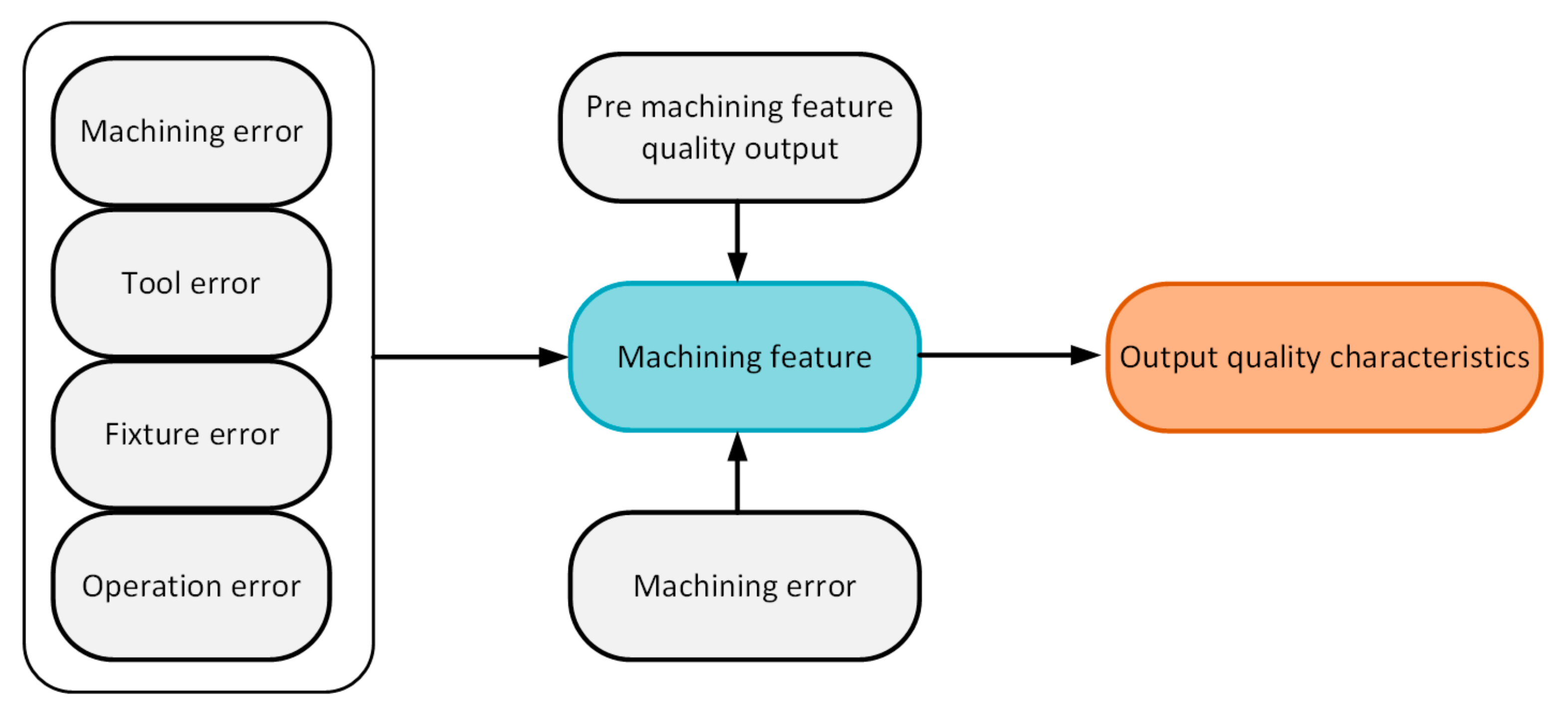
3.1.1. Definition of Error Propagation Network Nodes

The network nodes in the diesel engine body machining error transfer network can be divided into machining element nodes, machining feature nodes, and quality feature nodes. The relationship between the nodes can be described as follows: the machining element nodes input errors to the machining features, while the machining level of the machining features is expressed by their output quality features. The transfer relationship between each machining feature is essentially a transfer relationship between the quality features output by the different machining features.
Based on the above description, the machining element node is defined as the direct error source before machining the machining features. It mainly includes the machine tool and fixture errors used in diesel engine body machining, as well as the worker’s operation errors. The modeling method of machining element nodes [7] is as follows:
(1)
Machine error: During the machining process of the machine body, the spindle runout of the machine tool will have a direct impact on its rotary accuracy. In this regard, the spindle vibration degree ε s of the machine tool is selected to characterize the machining state of the machine tool. The machine spindle vibration degree classification is shown in Table 1.
(2)
Fixture error: Fixtures are generally composed of components such as positioning elements and clamping devices. For the modeling of fixture error, the main consideration in this paper is the error of the positioning element. According to the actual process of the diesel engine body, the positioning elements used for body machining are divided into the V-block and angle iron, so the fixture error ε f in the body machining process is defined as:
ε f = Δ i + Δ j
where Δ i is the deviation of the actual angle of the positioning element from the ideal angle due to manufacturing errors.
Δ j —deviation of the actual position of the positioning element from the ideal position due to placement.
(3)
Tool error: Tool wear plays a very important role in tool deformation, and the tool error is expressed by the amount of tool wear ε T . The specific formula is:
ε T = t t
where t is the time the tool has been in use.
t —the theoretical life of the tool.
(4)
Operating error: Operating error ε c is defined as the difference in the worker’s operating level caused by the worker’s experience and thinking time. There is an exponential relationship between human behavioral performance and the physical stimuli to which they are exposed, as follows:
The exponential relationship between stimuli has the following [7]:
O ( ρ ) = O M ( 1 e ρ )
where O ( ρ ) is the behavior of a person following an external stimulus.
O M —the original performance of the person when not exposed to any external stimuli.
ρ —external stimuli that affect behavior.
Introducing this equation into the machining of diesel engine bodies, it can be expressed as [7]:
ε c = ρ e ( 1 e ρ t )
where ε c is the operating error.
ρ e —the operating experience of the operator.
ρ t —the thinking time factor of the operating worker.
Define worker experience as the level of proficiency achieved by an operator in the machining of a body to complete a process, quantified as [7]:
ρ e = H H M
where H is the number of times an operator completes a process.
H M —the total number of times the body of a particular model of diesel engine is machined.
The longer an operator’s thinking time is, the less likely it is that risks will arise during their operation, defining the thinking time as [7]:
ρ t = T T 0 T M T 0
where T is the total duration of a process task in the airframe.
T 0 —the auxiliary time of the process.
T M —the longest time used in the process processing history for this process.
To build a complete body processing error transfer network, after defining the processing features processing element error input before processing, it is also necessary to define the quality features node output by the processing features node. The diesel engine body is the main part of the diesel engine, and its accuracy requirements are high. For example, the crankshaft hole of the body needs to have a small surface roughness and high dimensional accuracy to reduce the friction of the crankshaft and ensure the smoothness of the crankshaft during the operation of the diesel engine. At the same time, the crankshaft bore, as a slender coaxial bore system, also has high requirements coaxially. Therefore, in this paper, the quality characteristics nodes in the diesel engine body machining error transmission network are divided into three types: surface quality, dimensional accuracy, and form accuracy.

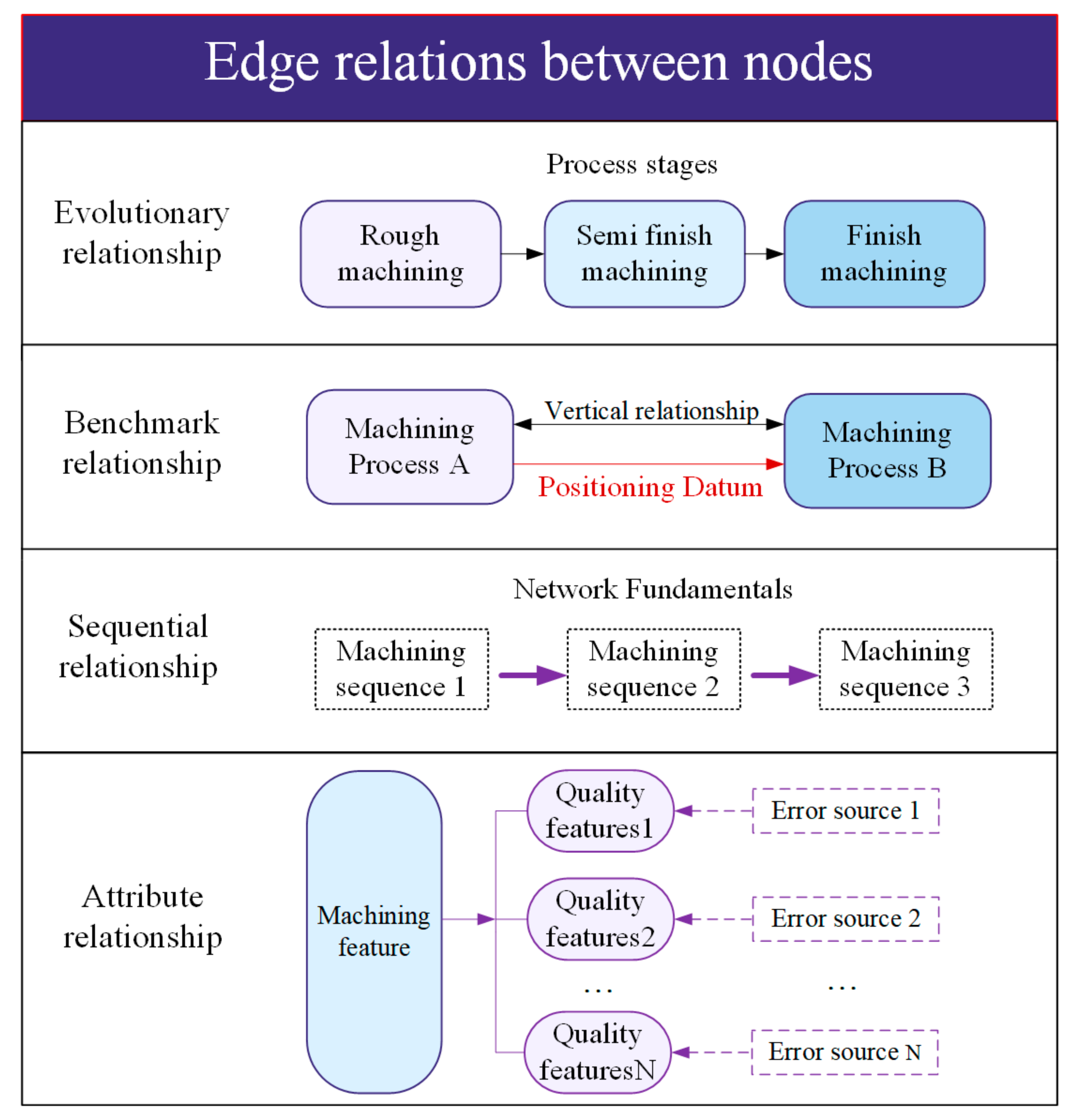
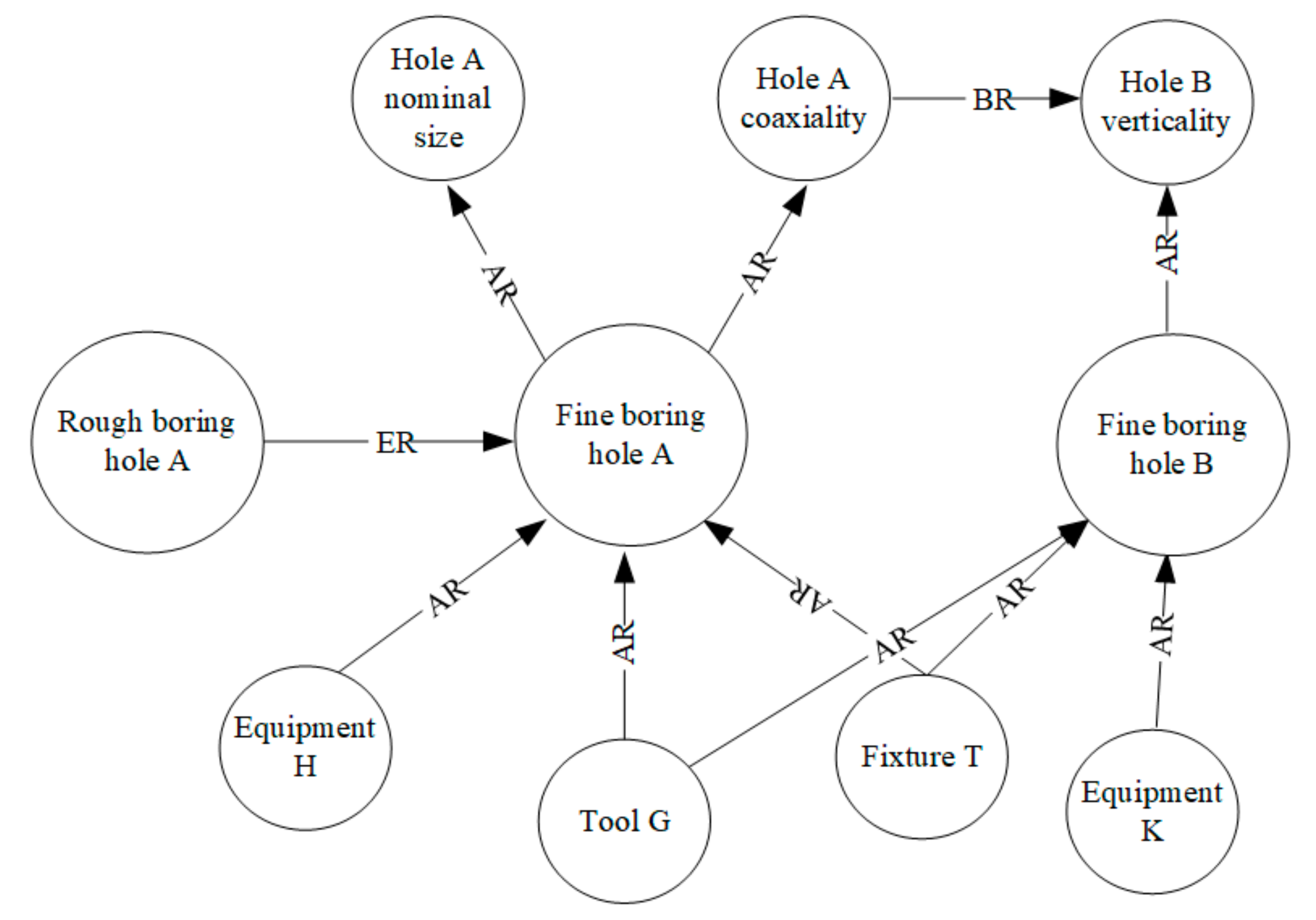
3.1.2. Definition of Edge Relationship of Processing Error Transfer Network

The transfer relationship between different nodes is described by directed line segments (edges) between body nodes, and this transfer relationship is defined as edge relationship. The edge relationship between nodes can be mainly divided into four forms: evolutionary relationship, benchmark relationship, sequential relationship, and attribute relationship. As shown in Figure 2, they can be described as follows.
  • Evolutionary relationship
The quality characteristics of the body often need to go through three stages from rough machining to semi-finishing to finishing when processing to meet the final quality requirements. This transfer relationship is, therefore, defined as an evolutionary relationship.
2.
Benchmark relationship
Before the machining of each process of the body, the step of determining its positioning reference is often indispensable. For example, the relationship between the crankshaft bore and the cylinder bore is vertical. The axis of the crankshaft bore is used as a positioning reference for the cylinder bore, and this transfer relationship is defined as the reference relationship.
3.
Sequential relationship
There is a sequence of machining for the machined features of the body. If you need to finish milling the cylinder bore face first, then finish boring the cylinder bore, and the sequence relationship is the premise of forming the transfer network of different machining features.
4.
Attribute relationship
A machining feature of the body usually contains multiple quality features, and there are multiple sources of error in the machining of a machining feature. The coupling relationship between such machining features and quality features and machining error sources is defined as an attribute relationship.

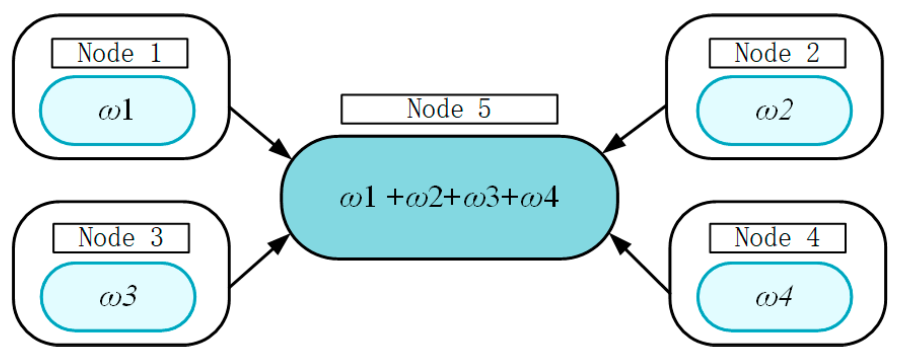
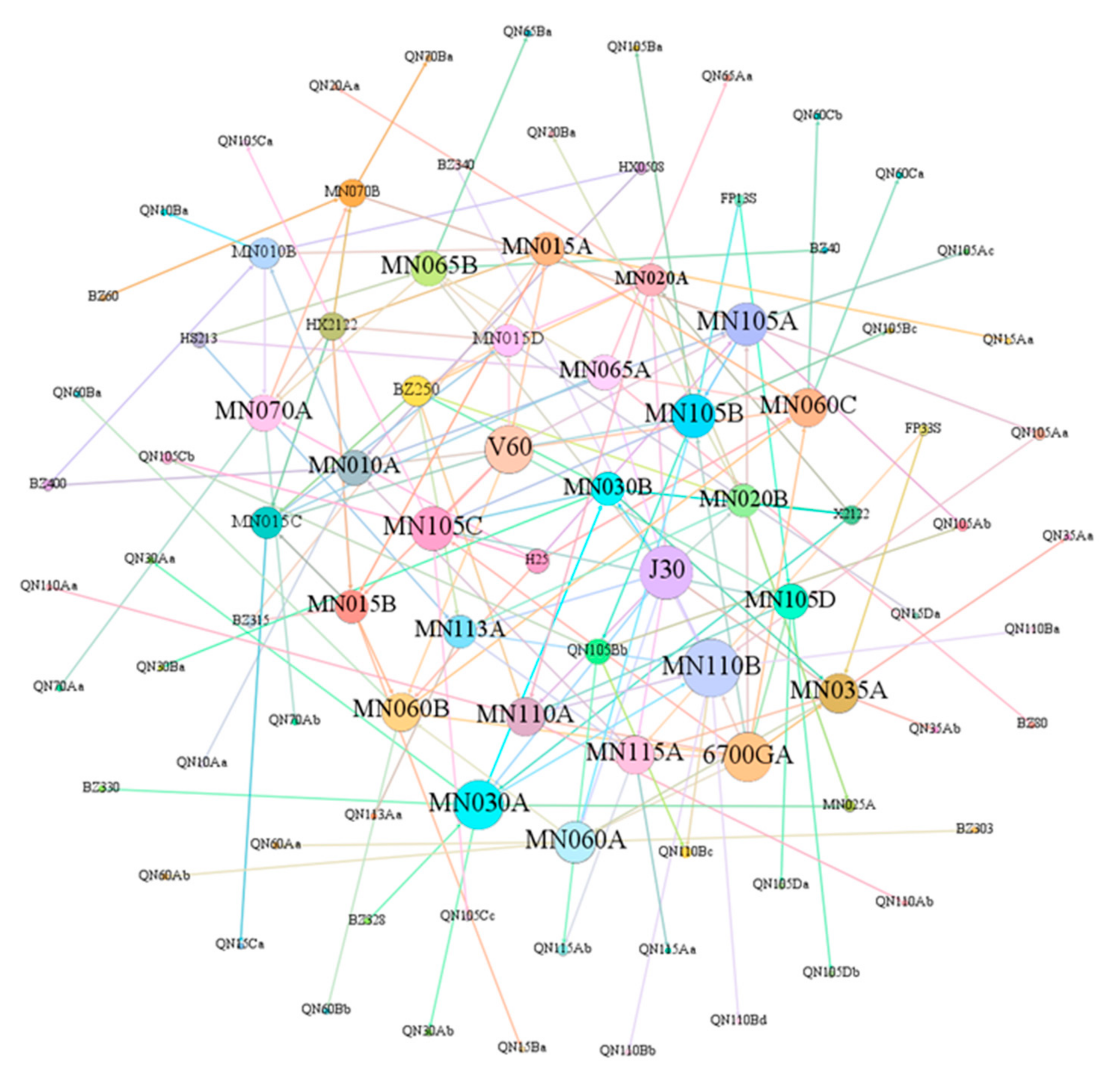
3.1.3. Construction of Processing Error Transfer Network

For the process error transfer network of a diesel engine body, its composition includes network nodes and connected edges between different nodes. It can be defined as <{W,M,Q},E>, where {W,M,Q} is the set of network nodes and E = {E1, E2, E3, …, En} represents the set of directed edges in the error transfer network, which describes the transfer relationship between the nodes.
According to the description of the edge relations of the process error transmission network, it is known that the transmission connection between different processing feature nodes mainly relies on the evolutionary, benchmark, and sequential relations. The transfer connection between a single processing feature node, quality feature node, and processing error source node relies on the attribute relationship. Among them, evolutionary, datum, and attribute relations are the main transmission channels of process errors. The error transfer network formed by the nodes with evolution, reference, and attribute relations is defined as the process error transfer sub-network. Figure 3 shows the schematic diagram of the process error transfer sub-network. The ER, BR, and AR in the figure represent the evolutionary relationship, benchmark relationship, and attribute relationship, respectively.
Based on the established machining error transfer sub-network of the body, the order relationship between the machining features has been informed. The machining error transfer network of the diesel engine body is finally formed by merging the established machining error transfer sub-networks.

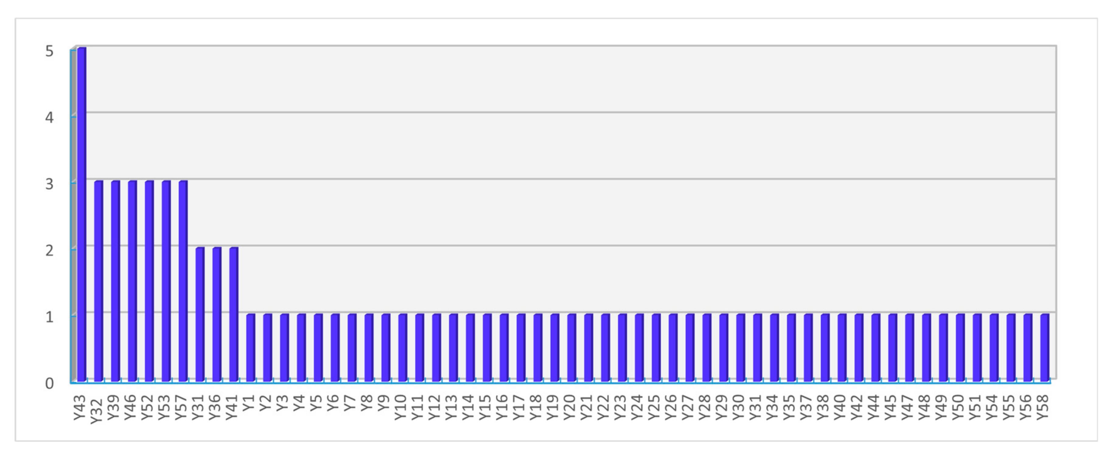
3.2. Analysis of Key Nodes of Error Transfer Network Based on Complex Network Theory

The machining error transfer network of a diesel engine body is a directed network, as shown in Figure 4. The criticality of a node should come from the sum of the weights of all the nodes pointing to that node. Therefore, before ranking the criticality of the nodes in the machining error transfer network of the body, the weights of each node need to be known first. However, in the actual body processing process, it is difficult to obtain the weights of each node purely through the processing process, excluding the human subjective judgment. For this reason, the PageRank algorithm [16] applied to Google web ranking is introduced to calculate the criticality of the network nodes in the body processing error transfer network.
The PageRank algorithm calculates the weights of each node after the first iteration by assuming that the weights of each node are the same, based on the initial weights of the nodes. After that, the node weights of the second iteration are calculated based on the node weights obtained in the first iteration, and so on, until the node weights converge to the true value. The iteration rule of the PageRank algorithm can be expressed as in Equation (8) [16]:
A = a 11 a 1 n a 1 M a m 1 a mn a mM a M 1 a Mn a MM
B i = A B i 1
where B i is the matrix of PageRank values of each network node obtained after the i-th iteration. The initial PageRank value of each node is the same value. That is, B i = {1/N, 1/N, …, 1/N} and a mn denote the number of edges from the m-th network node pointing to the n-th network node.
According to the above analysis, the diesel engine body process error transfer network is established, as shown in Figure 5. The size of the network nodes in the figure represents the size of its PageRank value, i.e., the larger the network node, the higher its importance.
According to the analysis results of the process error transfer network, the machining error source nodes of the V-block and angle iron used in the machining of the fuselage play an important role in the formation of the machining quality of the fuselage. The Kobelco gantry boring and milling machine with equipment number 6700 GA also plays an important role in the machining process of the fuselage. Among them, “V60” represents the single-port V-block with model number 60 mm; “J30” represents the angle iron with model number 30; “6700GA” represents the Kobelco gantry boring and milling machine with equipment number 6700GA. Take “MN110B” as an example, “MN” represents the key machining feature, “110” represents the finishing process with process number 110, “B” represents the machining process level, and others are similar.
Among the machining feature nodes, the machining feature nodes with larger PageRank values are defined as the key machining features of the machine body, and the process numbers are used to cluster them, and it can be found that the process numbers corresponding to the key machining features are 30, 35, 60, 105, 110, and 115 finishing process, respectively. Referring to the experience of the craftsmen, the analysis results are in line with the actual diesel engine body machining. In summary, the V-block, angle iron, 6700 GA boring and milling machine, and the key machining features of the body are jointly used as the key quality control points for body machining.
The quality feature nodes output by the processing feature type nodes are extracted, and the quality features are ranked by the node degree values. The node degree represents the degree of association of a node directly with its neighboring nodes. A larger node degree represents the greater chance of the quality feature producing defects and causing defects in the remaining quality features. The node degree is expressed as [16]:
λ = α + β
where λ is the node degree of the node, and α is the in degree, which is the number of edges pointing to the node. β is the out-degree, which is the number of edges passing outward from that node.
The node degree ranking of the quality features is shown in Figure 6. To make the network model of quality transfer more concise, the nodes Y53 (cylinder bore verticality), Y43 (crankshaft bore coaxially), and Y57 (camshaft bore coaxially) are described as quality features formed by one machining feature. Y53, Y43, and Y57 are quality features formed by several sub machining features, and their actual node degrees should be larger than the node degrees in the figure. Therefore, the quality features with higher mass transfer activity are cylinder bore verticality, camshaft bore coaxially, and crankshaft bore coaxially, respectively.

4. Diesel Engine Body Machining Quality Prediction

4.1. Modeling of Diesel Engine Body Machining Quality Prediction

4.1.1. Collection of Training Set Samples

Based on the established diesel engine body machining error transfer network, the diesel engine body machining quality prediction model is constructed as shown in Figure 7.
The output of the prediction model is some quality characteristic value of the machining feature output predicted by the body. The inputs are the machining element errors before the machining of the predicted machining feature, the process parameters used for the machining feature, and the quality characteristics of the output of the previous machining feature that influence the machining feature.
In the sample collection of the training set of the body machining quality prediction model, the machining element errors are calculated by the above equation. The process parameters are collected by the Latin hypercube method. The Latin hypercube experimental design has good uniformity and projection characteristics, which enables all test points to be distributed as uniformly as possible in the design space. Thus, the accuracy of the fitting of the enhancement factors and responses is achieved.

4.1.2. Support Vector Machine Regression Algorithm and Its Parameter Optimization

The diesel engine body is machined in small batches, and the inputs and outputs of the model are nonlinear in the established body machining quality prediction model. Therefore, the support vector machine regression algorithm (SVR), which has better results in nonlinear and small sample prediction, is introduced for prediction modeling [17].
The aim of the SVR algorithm [18] is to obtain a regression model, described as f(x) = ωTx + b, from the data in the training set. Thus, the predicted value of the mass feature f(x) and the corresponding true value of the mass feature y can be as close as possible. The SVR problem can be transformed into a convex optimization problem by Equation (10) [18]:
min 1 2 | | ω | | 2 + C i = 1 m ( f ( x i ) y i )
where C is the regularization constant, called the ε-loss function, which takes the following form [18]:
z = 0 ,                   if | z | ε ; | z | ε ,   otherwise
where ε is the error between f x and y tolerated by the SVR.
However, the mathematical nature of the function, as a discontinuous and non-convex function, makes it more difficult to solve Equation (10). By introduction slack variables ξ i , the formula is rewritten as [18]:
min 1 2 | | ω | | 2 + C i = 1 m ξ i ^ + ξ i s . t . f ( x ) y i ε + ξ i ^ , y i f ( x ) ε + ξ i , ξ i ^ 0 , ξ 0 , i = 1 , 2 , , m .
The Lagrange multiplier method is introduced to obtain the Lagrange function of Equation (12) [18]:
L = 1 2 | | ω | | 2 + C i = 1 m ( ξ i ^ + ξ i ) i = 1 m μ i ξ i i = 1 m μ i ^ ξ i ^ + i = 1 m α i ( f ( x i ) y i ε ξ i ) + i = 1 m α i ^ ( y i f ( x i ) ε ξ i ^ )
The pairwise problem of SVR is obtained by making the partial derivative of L, concerning ω , b , ξ i ^ , ξ i , zero and substituting it into Equation (13). The regression function of SVR is obtained after solving for it, as [18]:
f ( x ) = i = 1 m ( α i ^ α i ) k ( x i , x ) + b
where k ( x i , x ) = Φ ( x i ) T Φ ( x ) is the kernel function and Φ ( x i ) , and Φ ( x ) are the eigenvectors after the nonlinear mapping of x i and x .
According to the solution principle of SVR, the regularization constant C plays a direct influence on the complexity of the model and the degree of approximation error. The parameter g of the kernel function, on the other hand, relates to the radial range of action of the function. For this reason, this paper combines the K-fold cross-validation method and the grid search method to find the internal parameters C and g of the SVR.
One of the principles of the K-fold cross-validation method is to divide the data in the training set, divided before constructing the body processing quality prediction model into the K subset samples equally again. Then, each subset of the divided samples is used as the test set, and the remaining K-1 samples are used as the training set to obtain K sub-prediction models. Finally, the prediction accuracy of these K models is used as the prediction performance index of the model.
While the grid search method is an exhaustive method, its purpose is to perform an exhaustive search for the SVR internal parameters C and g by dividing the grid into M and N points equally in their respective regions, forming an M × N grid plane. Each combination of parameters can be computed with prediction accuracy by the K-fold cross-validation method described above. When the calculation traverses each node of the grid plane, the parameter combination with the highest prediction accuracy can be found, which is the optimal parameter. The flow chart of the body machining quality prediction model is shown in Figure 8.

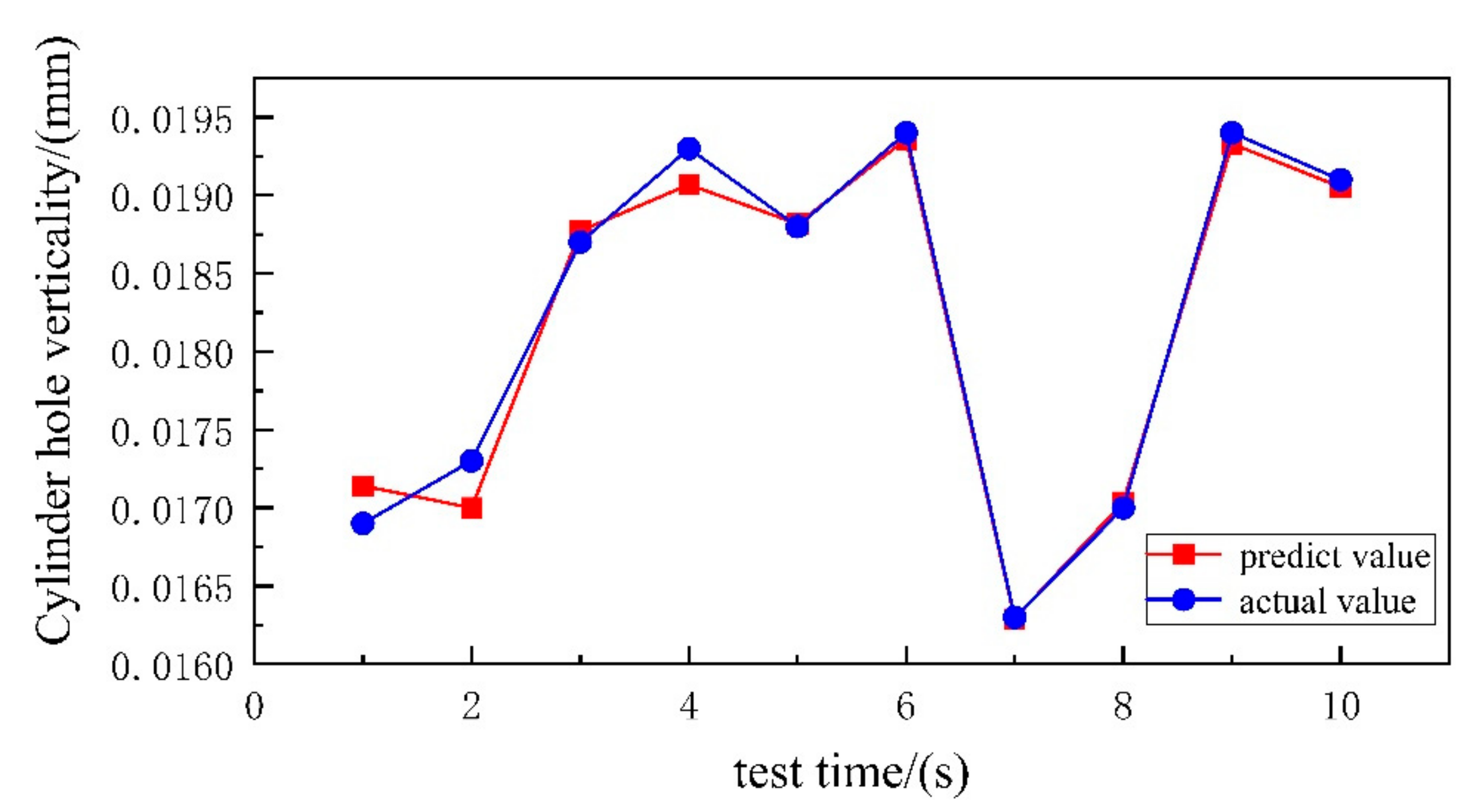
4.2. Instance Verification

To illustrate the machining quality prediction method of diesel engine block more intuitively, the paper takes the key control point “machining cylinder bore” obtained from error transfer network analysis to predict its key quality feature “cylinder bore verticality”.
For the machining of the cylinder bore, the machining reference is the axis of the crankshaft bore. Additionally, the predicted object “bore perpendicularity” is a common output of the former quality characteristic “crankshaft bore coaxially” obtained from the machining feature “finish boring cylinder bore” and the former process “finish boring crankshaft bore”. The crankshaft bore perpendicularity” is a common output of the former quality feature “crankshaft bore coaxially”. Therefore, the input of the cylinder bore perpendicularity prediction model should include the coaxially value of the crankshaft bore, in addition to the machining element error and process parameters. The experimental sample data are shown in Table 2.
The experimental sample data set were divided into training set and testing set, according to the ratio of 2:1, and the parameter K value of cross-validation method was taken as 5. The cross-validation and grid search methods were used to determine the optimal regularization constant C = 256 and the optimal kernel function parameter g = 0.000977 for the cylinder bore verticality SVR prediction model. According to the SVR prediction model of cylinder bore verticality after parameter optimization, the prediction results of the test set were obtained as shown in Figure 9. The blue line in the figure represents the real value of cylinder bore verticality, and the red line represents the predicted value of cylinder bore verticality.
The degree of fit of the model was judged using R squared, and the mathematical model was expressed as follows:
R 2 = i = 1 m ( y i y i ) 2 i = 1 m ( y i y i ¯ ) 2
where m is the number of test sample points, y i is the actual value of the test sample points, y i is the predicted value of the approximate model, and y i ¯ is the mean of the set of test sample points. When the R 2 value is closer to 1, the higher the accuracy of the approximate model.
The root means the square error is used to measure the deviation of the predicted value from the true value using an approximate model with the following mathematical model expression:
RMSE = i = 1 n ( y i y i ) 2 n
where n is the number of samples, y i is the true value, and y i is the predicted value.
The R-squared value of the cylinder hole verticality prediction model was 0.9834, and the RMSE value was 1.4738 × 10⁻⁴. From the results, we can see that the prediction results were more accurate and met the accuracy requirements of the body machining quality prediction.

5. Conclusions

In the paper, the error transfer relationship in the machining process of diesel engine body is considered, and the machining error transfer network of the body is established. Then, the error transfer network is analyzed. Finally, the prediction model of the quality characteristics of the body, based on the error transfer relationship, is established. The specific work can be summarized as follows:
  • Based on the transmission relationship between the processing features of the diesel engine block and the processing features and the processing elements, the processing error transmission network of the diesel engine block was established.
  • Based on the PageRank algorithm and the calculation of nodal degree values, the key quality control points and key quality features in the diesel engine body machining process were determined. The key quality control points were: “Fine-milling Haff surface”, “Fine-boring crankshaft bore”, “Fine-boring camshaft bore”, “Rough boring camshaft bore”, “Fine Boring of Cylinder Bore”, “Rough Boring of Cylinder Bore”, “V Block”, “Machine 4”, and “Tool 1”. The key quality features were: “Cylinder bore verticality”, “Crankshaft bore coaxially”, and “Camshaft bore coaxially”.
  • Based on the error transfer relationship, the machining quality prediction model of the diesel engine body was established by using the SVR algorithm after parameter optimization. The validity of the method was finally verified by an example.
Compared with Reference [19], which describes the evaluation of the process reliability of diesel engine blocks. This paper not only describes the establishment of the diesel engine block machining error transfer network, but also determines the optimal combination of the critical quality control points and features that are consistent with the machining by means of the importance algorithm. It can guide the processing production of the diesel engine body more effectively and improve its overall processing quality. Since the processing process of the diesel engine body is complicated, this paper optimizes the error transfer relationship between the machining quality of the body and obtains more satisfying and accurate results.

Author Contributions

Conceptualization, Methods, L.S.; Data organization, X.R.; Funding acquisition, Resources, H.Z.; Supervision, Resources, G.L.; Visualization, Writing-review and editing, W.Y.; Software, J.Z.; Formal analysis, Y.L. All authors have read and agreed to the published version of the manuscript.

Funding

This work was supported by the National Natural Science Foundation of China (No. 62203193) and the general project of natural science research for the Institutions of Higher Education of Jiangsu Province of China (No. 21KJB510016).

Institutional Review Board Statement

Not applicable.

Informed Consent Statement

Not applicable.

Data Availability Statement

Not applicable.

Conflicts of Interest

The authors declare no conflict of interest.

References

  1. Zheng, S.Y.; Yu, J.B.; Liu, H.Q.; Cheng, F.; Sun, X.W.; Wu, H.H. Modeling and analysis of adaptive weighted deviation transfer network for hybrid multi-stage machining process. J. Mech. Eng. 2018, 54, 179–191. [Google Scholar] [CrossRef]
  2. Dong, H.; Feng, Y. Intelligent prediction model of body size assembly quality based on XG Boost. Ind. Eng. 2021, 24, 77–82. [Google Scholar]
  3. Lu, Z.; Dai, W.; Zhao, Y. Reliability evaluation and analysis of grinding process based on machining physics. Mater. Res. Innov. 2015, 19 (Suppl. S5), s5-1065–s5-1069. [Google Scholar] [CrossRef]
  4. Selvakumar, S.; Arulshri, K.P.; Padmanaban, K.P. Machining Fixture Layout Optimization Using Genetic Algorithm and Artificial Neural Network. Int. J. Manuf. Res. 2013, 8, 171–195. [Google Scholar] [CrossRef]
  5. Mo, D.S.; He, Y.; Yu, Y.Y. Quality control and prediction of injection molding based on RBF neural network and genetic algorithm. Plast. Ind. 2020, 48, 71–76. [Google Scholar]
  6. Hertlein, N.; Deshpande, S.; Venugopal, V.; Kumar, M.; Anand, S. Prediction of selective laser melting part quality using hybrid Bayesian network. Addit. Manuf. 2020, 32, 101089. [Google Scholar] [CrossRef]
  7. Li, Y.; Zhang, F.P.; Yan, Y.; Zhang, T.H.; Zhou, J.H.; Guo, F.Y. Multi-process manufacturing quality modeling based on statistical quantification of process factors. J. Mil. Eng. 2020, 41, 1408–1416. [Google Scholar]
  8. Huang, J.D.; Wang, L.S.; Li, G.F. A least squares support vector machine based on surface roughness prediction system for cylindrical grinding. Opt. Precis. Eng. 2010, 18, 2407–2412. [Google Scholar]
  9. Ashtiani, H.R.R.; Shahsavari, P.A. Comparative Study on the Phenomenological and Artificial Neural Network Models to Predict Hot Deformation Behavior of Al-Cu-Mg-Pb Alloy. J. Alloy Compd. 2016, 687, 263–273. [Google Scholar] [CrossRef]
  10. Portillo, E.; Marcos, M.; Cabanes, I.; Zubizarreta, A. Recurrent ANN for monitoring degraded behaviors in a range of workpiece thicknesses. Eng. Appl. Artif. Intell. 2009, 22, 1270–1283. [Google Scholar] [CrossRef]
  11. Lu, C. Study on prediction of surface quality in machining process. J. Mater. Process Technol. 2008, 205, 439–450. [Google Scholar] [CrossRef]
  12. Zheng, W.; Zhou, M.; Zhou, L. Influence of process parameters on surface topography in ultrasonic vibration assisted end grinding of SiCp/Al composites. Int. J. Adv. Manuf. Technol. 2017, 91, 2347–2358. [Google Scholar] [CrossRef]
  13. Tirkel, I. Cycle time prediction in wafer fabrication line by applying data mining methods. In Proceedings of the 2011 IEEE/SEMI Advanced Semiconductor Manufacturing Conference, Saratoga Springs, NY, USA, 16–18 May 2011. [Google Scholar]
  14. Zajac, J.; Hatala, M.; Duplák, J.; Dupláková, D.; Steranka, J. Experimental high speed milling of the selected thin-walled component. TEM J. 2017, 6, 678. [Google Scholar]
  15. Duplak, J.; Duplakova, D.; Hatala, M.; Radchenko, S.; Sukic, E. Surveying the topography and examining the quality of the machined surface of selected hardened steels in the milling process. J. Eng. Res. 2021, 9, 285–301. [Google Scholar] [CrossRef]
  16. Li, K.; Wu, W.; Liu, F.S.; Chen, G.H.; Chen, S.H. Important node assessment of weapon and equipment system based on PageRank algorithm. Firepower Command. Control 2017, 42, 34–37+42. [Google Scholar]
  17. Han, D.; Zheng, J.R. Approximate modeling techniques in engineering optimal design. J. East China Univ. Sci. Technol. (Nat. Sci. Ed.) 2012, 38, 762–768. [Google Scholar]
  18. Lu, J.; Zhang, Z.K.; Wu, Z.Q.; Ma, J.Y.; Liao, X.P.; Hu, S.S. Surface roughness prediction of creeping graphite cast iron based on support vector machine. Surf. Technol. 2020, 49, 339–346. [Google Scholar]
  19. Zhou, H.; Yang, W.; Sun, L.; Jing, X.; Li, G.; Cao, L. Reliability optimization of process parameters for marine diesel engine block hole system machining using improved PSO. Sci. Rep. 2021, 11, 21983. [Google Scholar] [CrossRef] [PubMed]
Figure 1. Diesel engine body machining error transfer network establishment and quality prediction scheme.
Machines 10 01081 g001
Figure 2. Edge relations between nodes.
Machines 10 01081 g002
Figure 3. Process error transfer sub-network.
Machines 10 01081 g003
Figure 4. Calculation of node criticality.
Machines 10 01081 g004
Figure 5. Diesel engine body machining error transfer network.
Machines 10 01081 g005
Figure 6. Quality feature node degree ranking.
Machines 10 01081 g006
Figure 7. Schematic diagram of the diesel engine body machining quality prediction mode.
Machines 10 01081 g007
Figure 8. Flow chart of the optimized SVR algorithm.
Machines 10 01081 g008
Figure 9. Cylinder bore verticality prediction results.
Machines 10 01081 g009
Table 1. Machine tool spindle vibration classification table.
Spindle Vibration LevelEvaluation
0Vibration-free
0.1~0.3Light vibration, machine in finishing condition
0.4~0.6Medium vibration, the machine is in rough machining, vibration is high, but in fair condition
0.7~0.9Heavy vibration, serious machine vibration, and poor running conditions should be avoided as much as possible
1Severe vibration should be stopped immediately
Table 2. Cylinder hole verticality experiment sample data sheet.
Serial
Number
InputOutput
Pre-Mass
Features
“Fine Boring of Cylinder Bores”
Processing Element Error
Process ParametersQuality Characteristics
Coaxial of Crankshaft BoreMachine
Tool Error
Clamp ErrorTool
Error
Operating ErrorsRotational
Speed (r/min)
Feed
Rate (mm/min)
Cutting Depth
(mm)
Cylinder Hole Verticality
10.07180.10.110.0940.069130.219.50.540.0186
20.07220.20.0910.0890.0712419.10.520.0189
30.06640.10.0860.0930.071138.819.40.420.0168
40.07490.10.0850.0780.072145.318.10.510.0187
50.07560.10.0940.0880.062126.921.70.570.0188
210.07350.10.0860.0790.069131.921.40.350.0169
220.07080.10.1020.0730.071144.217.10.40.0173
230.07560.20.110.0730.066124.623.30.450.0187
240.0780.10.0940.0790.071122.421.50.490.0193
250.07610.10.1130.0680.062126.120.40.620.0188
260.07560.10.0840.0930.071133.419.30.560.0194
270.07080.10.1060.0610.065129.315.60.450.0163
280.07510.10.0820.0860.063121.417.50.420.017
290.07230.20.0830.0880.069117210.590.0194
300.07040.10.0980.0680.07127.724.40.650.0191
Publisher’s Note: MDPI stays neutral with regard to jurisdictional claims in published maps and institutional affiliations.

