Article

Investigating the Combined Effect of Multiple Dent and Bump Faults on the Vibrational Behavior of Ball Bearings

1
Industrial and Manufacturing Engineering Department, School of Innovative Design Engineering, Egypt-Japan University of Science and Technology, New Borg El-Arab City 21934, Egypt
2
Mechanical Design and Production Engineering Department, Faculty of Engineering, Assuit University, Assuit 71515, Egypt
3
Department of Mechanical Engineering, Faculty of Science and Technology, Keio University, Yokohama 223-8522, Japan
4
Production Engineering Department, Faculty of Engineering, Alexandria University, Alexandria 21928, Egypt
*
Author to whom correspondence should be addressed.
Machines 2022, 10(11), 1062; https://doi.org/10.3390/machines10111062
Submission received: 6 October 2022 / Revised: 22 October 2022 / Accepted: 2 November 2022 / Published: 10 November 2022
(This article belongs to the Section Machines Testing and Maintenance)

Abstract

:
The rolling element bearing is a fundamental component of any rotating machinery. During operation, wear debris and lubricant impurities create dents and bumps on the bearing raceway surfaces. Such localized defects produce transient vibration impulses at one of the bearing characteristic frequencies. Having a combination of multiple types of point defects on the raceway results in superimposed vibration patterns, which reduce the ability to recognize these defects’ effects. In this paper, a 6-DOF dynamic model is developed to accurately investigate the vibration characteristic of a ball bearing with a multipoint defect comprising a dent and bump on its raceway surface. The model considers the effects of time-varying contact force produced due to defects, lubricant film damping, bearing preload, and the inertia effect of rolling elements. The simulation results reveal the vibration behavior of multipoint defect bearings. In addition, bearing vibration response is affected by the number of defects, the angle between them, and the type and size of each defect. Furthermore, it is challenging to predict bearing defects parameters such as the numbers, types, sizes, and angles between adjacent defects from acceleration signal analysis without jerk signal analysis. The validation of the model is proved using signals from the Case Western University test setup.

1. Introduction

The rolling element bearing (REB) is an important mechanical element used to support rotating machinery and prevent frictional contact between rotating and fixed parts. Unexpected failures of REBs cause major machinery malfunctions, breakdowns, and production losses [1]. According to some statistics, REB problems represent 44% of induction motor failures [2,3].
Defects in REBs are classified into localized and distributed bearing faults. Distributed defects, such as waviness, surface roughness, or off-size rolling elements, are generally caused by manufacturing errors. In contrast, insufficient lubrication film and rolling contact fatigue are the prime initiators of localized defects [4]. Localized defects account for 30% of rotating machine faults, according to an Electric Power Research Institute (EPRI) survey [5]. These faults usually originate from rolling contact fatigue in the surface or subsurface cracks. During operation, rolling contact fatigue causes gradual propagation of these cracks, which combine and cause material loss from the inner race, outer race, or rolling elements, forming spalls or dents [5]. Other forms of localized defects, such as bumps in bearing raceways, are normally generated by debris or grease impurities trapped between the ball–raceway interface, which adheres to the surface [6].
Once a localized defect is formed on the raceway, the rolling elements repeatedly strike over it, at which a corresponding abrupt change in contact pressure occurs. These fluctuations in contact pressure generate a sequence of short-time impulse bursts, causing abnormal transient vibration impulses and exciting the high-frequency resonant modes of the bearing structure [7]. Gradually, the edges of the localized pit/spall wear as the rolling parts pass over it repeatedly, causing the formation of an extended fault [8].
Early fault detection and identification help reduce REB failure costs and consequences. Vibration analysis provides critical information on rolling bearing health over time [9]. A bearing localized defect is identified in raw vibration signals in the time domain and frequency domain by repeated transient impulses at one of the bearing characteristic frequencies [10]. At early stages, the initiated faults have low energy levels and are submerged in background noise and low-frequency signal components.
Over the past years, different approaches have exploited vibration data to detect and diagnose REB faults at early stages. These approaches can be classified into model-based and signal-processing-based methods [11]. Signal processing methods include spectral analysis methods [12,13], time-frequency analysis methods [14,15], wavelet filtration [16,17,18], cyclostationary analysis [19,20,21], and empirical and variational mode decomposition methods [22,23,24]. Although signal processing techniques tackle a wide range of industrial problems, they are data-driven methods. These techniques require, in many cases, an in-depth understanding of the nonlinear dynamic behavior of rolling bearings, such as internal radial clearances [25], and the effect of multipoint fault locations and sizes for more effective development of fault diagnosis algorithms.
Dynamic modeling of REBs provides extensive information on bearing vibration response and provides guidance for the manifestation of different fault geometries and multifault combined effects in transient impulsive signals. This enhances the understanding of the generated vibration in faulty bearings and their dynamic characteristics, which aids in developing more accurate fault diagnosis algorithms and enhancing rolling bearing design and lifetime prediction [26].
Gupta [27,28] was the first to develop and analyze 3D bearing motion. Ghaisas et al. [29] simplified analytical models of contact forces and established a discrete element model. In previous dynamic bearing simulations, all bearing components were modeled assuming defect-free raceways and balls. Several REB dynamic models have been created over the last several decades to anticipate the vibration response of bearings due to distributed defects such as raceway waviness [30,31], off-sized rolling elements [32], raceway out-of-roundness [33], and misalignment rotor ball bearing systems [34,35].
Dynamic models for rolling bearings having localized surface defects on the inner raceway, the outer raceway, or the rolling elements have received extensive attention in the past decade. The vibration response of localized defect rolling element bearing was investigated using a rectangular displacement excitation model [36,37,38,39]. Using a half-sine displacement excitation model, Patil et al. [40] established a theoretical model to develop the vibration response of a ball bearing with a circumferential spall. Liu et al. [41] used a piecewise excitation function to model a spall defect. On the other hand, Singh et al. [42] proposed an explicit finite-element model to simulate the vibrations of a rolling element bearing with a spall defect on its outer raceway surface.
Many research efforts in the literature have modeled defective rolling bearings considering spall defects, while little research has addressed dent and bump defects. Ashtekar et al. [6] developed a dynamic model to investigate the effects of surface irregularities such as dents, bumps, and debris on deep-groove ball bearing vibrations. This model applied Hertzian contact theory and the superposition principle to calculate the contact force between rolling elements and defective raceways. To investigate the influence of a raceway dent on tapered roller bearing vibrations, Li and Kang [43] constructed a three-dimensional vibration model of a bearing based on Hertzian contact theory and an electrohydrodynamic lubrication model to simulate the nonlinear interactions between bearing components. Liu et al. [44] introduced shoulders on the dent sides and studied their combined influence on ball bearing dynamics. Shi et al. [45] proposed a dynamic model to study the effect of hemisphere bump defects on the vibration response of cylindrical roller bearings. A semi-sinusoid function was used to model the excitation effect of a bump on the inner raceway.
While most previous works have focused on localized single defects in bearings, in actual practice, multiple localized defects are common. Furthermore, point defects may not necessarily lead to the immediate replacement of a bearing in machines until they progress to form multiple localized faults on bearing raceway surfaces. The vibration response of bearings with multiple localized defects is more difficult to interpret using conventional dynamic models [46]. Early attempts by McFadden and Smith [47] formulated a dynamic model to describe the vibration response of bearings with multiple rectangular defects and analyzed the effect of the phase angle between defects on vibration response. This analysis shows that varying phase angles lead to modifying the shape of the vibration spectrum, and the largest amplitude of the vibration signal is not necessarily located at a faulty frequency. In their significant work, Zhang et al. [48] proposed a 4-DOF dynamic model to study the vibration response of deep-groove ball bearings with compound rectangular shape defects under different operating conditions. Recently, a 4-DOF dynamic model of a ball bearing with multiple defects was developed to study the influence of multiple rectangular spall defects, the angle between defects, and the location of defects on the obtained vibration response [49].
One limitation in previous studies is that they predicted the vibration response characteristics induced by rectangular multiple defects. However, a rectangular shape is impractical to occur, and it is believed that the edges and surfaces of a rectangle fault tend to be deformed and rounded with the repetitive rolling action of bearing elements over them. Furthermore, little effort has focused on modeling the combined effect of different types of localized faults on the obtained transient impulses of faulty bearings. This paper proposes an improved nonlinear dynamic model of a deep-groove ball bearing with hemispherical-shaped dents and bumps rather than rectangular-shaped defects located simultaneously on either the inner or the outer race surface. The dynamic model has 6-DOF that includes the bearing shaft’s and bearing housing’s flexibility and simulates a typical high-frequency resonant response of the bearing. The time-varying compliance and time-varying displacement produced due to defects are considered in the model. The model also takes into consideration the oil film lubrication damping, the effect of bearing preload, and the inertia effect of rolling elements. Additionally, this paper investigates the influence of the angle between adjacent defects, the size of defects, and the number of defects on the vibration response of the defective bearing.

2. Dynamic Modeling of the Ball Bearing

The multibody nonlinear dynamic model used to predict the vibration response of a rolling element bearing with a bump and dent in each raceway is depicted in Figure 1. In this model, rolling elements and bearing raceways are considered rigid. The slipping between the bearing components is not taken into account. Furthermore, contact deformations between the rolling element and raceway are considered elastic, and any localized plastic deformations are ignored. The proposed 6-DOF model includes the horizontal and vertical displacements of the outer and inner races (xo, yo, xi, and yi) and the measured vibration response (xr, and yr). The model consists of a mass mi, representing the inner raceway and shaft, and a mass mo, representing the outer raceway and bearing support structure.
The spring and damper constants (kix, kiy, kox, koy, cix, ciy, cox, and coy) represent the stiffness and damping of the bearing shaft and support structure. Time-varying nonlinear contact springs (Kj) are used to model the Hertzian contacts between rolling elements and raceways. In addition, the damping of the lubricant layer in the contacts is modeled using linear dampers (Cj). As demonstrated by previous studies [50,51], a 2-DOF unit resonator was implemented to simulate a typical high-frequency resonant response of the bearing. This resonator unit consists of two masses (mr) attached to the outer raceway via a spring (kr) and damper (cr).

2.1. Defect Shape Modeling

The leading cause of bumps in REBs is the presence of debris between the rolling element and the raceway. The debris may be lubricant impurities or induced by fatigue spalling. The profile of bumps on the raceway is approximated as a hemisphere, as shown in Figure 2a [6,45]. On the other hand, debris particles, brinelling, and surface spalls are the leading causes of dents on bearing raceways. The basic geometry of a dent can be idealized as a hemispheroidal shape, whose size is defined by diameter d and depth h, as shown in Figure 2b [52,53].
When a ball passes over a localized defect, the clearance of the bearing assembly suddenly changes compared to the normal bearing case, as illustrated in Figure 1c,d. This change will lead to a sudden variation in the contact deformation (displacement) between the ball and the inner/outer raceways. The change of contact deformation (Hdik) (displacement) can be expressed by a half sinusoid function, as described in Equation (1):
H d j k ( t ) = { h ¯ s i n ( π θ d j k   ( m o d   ( φ j ( t ) , 2 π ) θ d j k ) ) ,     θ d j k m o d   ( φ j , 2 π ) θ d j k + θ d k   0                                                                   ,                                                             O t h e r    
where θdjk is the localized defect width in the angular domain, which can be calculated by Equation (2) as follows:
θ d j k = d k / D d
Dd is the raceway diameter with a defect. θdjk is the initial angular offset of defect k to the jth ball. Φj is the relative angular position of the jth ball relative to the outer race or the inner race, which can be determined using Equation (3):
φ j ( t ) = {   2 π ( j 1 ) / z + ω c t ,                                   f o r   o u t e r   r a c e 2 π ( j 1 ) / z + ( ω s ω c ) t ,       f o r   i n n e r   r a c e
where z is the number of rolling elements, ωs is the shaft angular velocity, ωc is the cage angular velocity, and h ¯   is the maximum deformation change due to local defects. In the case of a bump defect, the value of h ¯ will equal to the bump height, while in the case of a dent defect, it can be calculated by Equation (4) as follows:
h ¯ = d b 2 ( d b 2 ) 2 ( d 2 ) 2
where db is ball diameter.

2.2. Time-Varying Contact Force

The contacts between the rolling elements and the raceways are modeled using a series of nonlinear springs. The equivalent contact stiffness of the rolling element with the inner and outer raceways is calculated by:
K = ( 1 ( 1 / k i ) 1 / n + ( 1 / k o ) 1 / n ) n
where n is the load–deflection exponent, which is equal to 3/2 for ball bearing [54]. ki and ko represent the contact stiffness between the rolling element and the inner and outer raceways, respectively, which are calculated by Equation (6) according to [8,54] as follows:
K i o = 2.15 × 10 5 ( ρ b i b o ) 1 2 ( δ i o ) 3 2
where ρ b i b o is the sum of the curvature of the rolling element and inner/outer raceway, and δ i o is the dimensionless contact parameter. The values of ρ b i b o and δ i o   are calculated by the method described in [55].
The rolling elements only come into direct contact with the raceways when they are in the loading zone. Otherwise, the rolling element and raceways are in a separate state. The location of the jth ball in the loading zone is estimated using the Dirac function βj, which can be described as:
β j ( t ) = { 1 ,     δ j ( t ) 0 0 ,     δ j ( t ) > 0
where δj is the relative radial displacement between the jth ball and raceways. According to Figure 1, the radial displacement at any rolling element angular position can be described as:
δ j ( t ) = ( x i ( t ) x o ( t ) ) c o s θ i ( t ) + ( y i ( t ) y o   ( t ) ) s i n θ j ( t ) γ + Δ i + Δ o
where γ is the bearing radial clearance, ∆I and ∆o are the inner race expansion deformation and outer race compression deformation caused by interference fit, whose value depends on interference value [56], and θi is the angular position of the jth rolling element relative to the y-axis, which is calculated by Equation (9) as follows:
θ j ( t ) = 2 π ( j 1 ) / z + ω c t
According to Hertzian contact theory, the normal contact force between the jth ball and raceways for a healthy bearing is given by Equation (10) as follows:
F j ( t ) = K β i ( t ) δ i ( t ) n
where Fj is the normal contact force between the jth ball and raceways. When a surface defect (bump or dent) exists in the bearing raceways, the contact pressure substantially changes over the local defect area each time a rolling element passes over it [6,57]. Consequently, the normal contact force between the rolling element and raceway varies, and the amount of this variation for a bump defect is estimated using Equation (11) according to [6] as follows:
F d j k ( t ) = ±   K b / d   H d j k ( t ) 3 2
where Fdjk is the normal force over the k defect due passing of the jth ball over it, and Kb/d is the equivalent local defect Hertzian stiffness, which can be calculated by considering the bump or dent as hemisphere according to the methodology described in [58]. The dent and bump defects have opposite effects on the contact pressure, i.e., the change in normal contact force due to dent Fdjk is the inverse of the change in the force value due to the bump [6] so that Fdjk has a positive sign for a bump defect and a negative one for a dent defect. By considering the Hertzian contact force and centrifugal force ( F c ) of rolling elements [30], the restoring force of the x and y components is calculated by Equation (12).
{ F x   ( t ) F y   ( t ) } = i = 1 z ( F j ( t ) + k = 1 N d F d j k   ( t ) F c )     { c o s θ i ( t ) s i n θ i ( t ) }                    
where the centrifugal force (Fc) of the rolling elements due to rotation about the bearing axis is given by Equation (13) [54,59] as follows:
F c = 2.06 × 10 9 d b 3 ω c 2 D p

2.3. Contact Damping force

The lubricant film that separates the rolling element from the raceway is the primary source of contact damping. The lubricant is supposed to exhibit Newtonian behavior. Hence, the contact damping force of the jth rolling element may be determined using Equation (14):
F d j ( t ) = C j δ j ˙ ( t )   β j ( t )
where C j is the viscous damping coefficient, and δ j ˙ ( t ) is the relative velocity between the jth rolling element and raceways, and may be calculated by:
δ j ˙ ( t ) = ( x i ˙ ( t ) x o ˙ ( t ) ) c o s θ i ( t ) + ( y i ˙ ( t ) y o ˙   ( t ) ) s i n θ j ( t )
The x and y components of the total damping force can be calculated by Equation (16) as follows:
{ F d x   ( t ) F d y   ( t ) } = i = 1 z     F d j ( t ) { c o s θ i ( t ) s i n θ i ( t ) }          
The value of the viscous damping coefficient is determined to ensure that the total damping in the bearing system is in order of 0.25 2.5 × 10 5 times the linearized stiffness of the bearing system [8].

2.4. Dynamic Equations of Ball Bearing

Based on the bearing model shown in Figure 1, and according to Newton’s second law, the dynamic equations of motion for the ball bearing inner race, outer race, and resonator unit are described by:
{ m i x ¨ i + c i x x ˙ i + k i x x i + F x + F d x = Q x m i y ¨ i + c i y y ˙ i + k i y y i + F y + F d y = Q y
{ m o x ¨ o + ( c o x + c r ) x ˙ o + ( k o x + k r ) x o c r x ˙ r k r x r F x F d x = 0 m o y ¨ o + ( c o y + c r ) y ˙ o + ( k o y + k r ) y o c r y ˙ r k r y r F y F d y = 0
{ m r x ¨ r + c r ( x ˙ r x ˙ o ) + k r ( x r x o ) = 0 m r y ¨ r + c r ( y ˙ r y o ) + k r ( y r y o ) = 0
where Qx and Qy are the horizontal and vertical components of the externally applied radial load on the bearing. The dynamic bearing model consists of a system of nonlinear second-order differential (Equations (17)–(19)). This dynamic model is parametrically excited by a sudden change of Fx and Fy. The passing of rolling elements over the localized defect will cause an abrupt change of relative displacement between the rolling element and raceways and a change of contact stiffness, which leads to a change of contact force between the jth rolling element and the raceway and, finally, a sudden change of Fx and Fy, which cause impulsive excitation of the dynamic system.
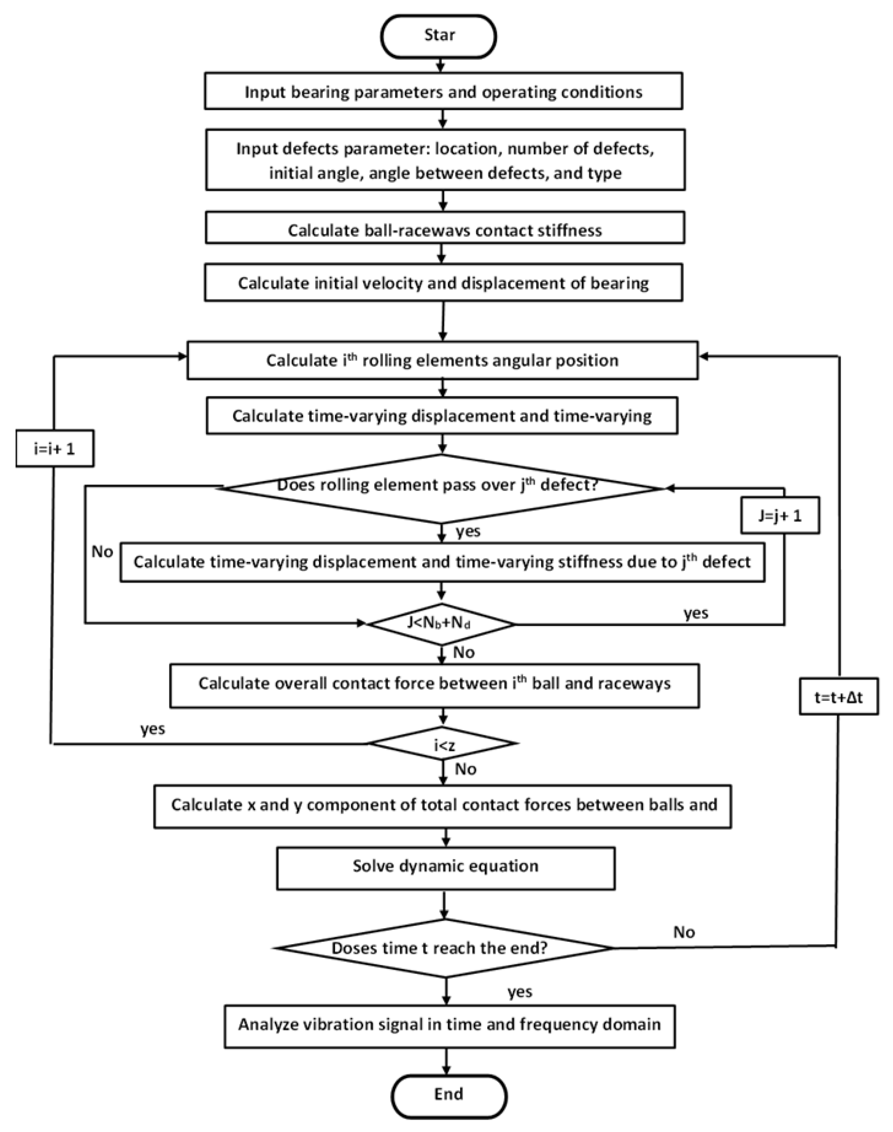
The numerical solution of Equations (17)–(19) for the developed model is solved using the fourth-order Runge–Kutta method with a constant time step. The solution procedure flow chart is illustrated in Figure 3.
A deep-groove ball bearing (6205-2RS JEM SKF) is used in this study, and its geometrical specifications are listed in Table 1. The bearing shaft is selected to rotate at 1797 rpm under zero external load in the simulation environment. Moreover, the simulation time step is 6 µs, and the initial displacement of the inner race is 1 µm in the x- and y-directions, while the initial velocity is 0 in the horizontal and the vertical direction [59].

3. Numerical Results

3.1. Simulation Results of Bearing with Double Dents

The results of the modeled bearing running with two identical dents located on its outer raceway are obtained by solving Equations (17)–(19), as shown in Figure 4 and Figure 5. In the simulation model of the defective bearing, the phase angle between the two dents is selected to be 15°, the dent diameter is 0.17 mm, and the dent depth is 0.28 mm. The location of the first dent is the intersection between the x-axis and the outer raceway at the heavily loaded zone.
When comparing the dynamic response of a healthy bearing and a defective one, which are shown in Figure 4a and Figure 5a, it is clear that the vibration signal exhibits periodic transient impulses with remarkable amplitudes, depending on the size and shape of faults. The normal bearing, on the other hand, shows transient periodic impulses due to fluctuations of resultant dynamic force (Fx, Fy, Fdx, Fdy) [62]. The envelope spectrum of healthy and defective bearings, which are shown in Figure 4b and Figure 5d, respectively, reveals that BPFO and its harmonics are dominant modulation components for both bearings. Furthermore, the peak amplitude at BPFO frequency and its harmonics for the healthy bearing is insignificant compared with peaks for the defective one.
The passing of rolling elements over Dents 1 and 2 generates 21 impulses during a 0.1 s period, as shown in Figure 5b. The time delay indicates that Impulses 1 and 3 are created due to the passing of rolling elements over Dent 1, whereas rolling elements passing over Dent 2 generate Impulses 2 and 4. Furthermore, the duration between Impulses 1 and 3 and Impulses 2 and 4 is 9.3 ms, which is approximately equal to 1/BPFO, where BPFO is the ball bass frequency on the outer race.
Igarashi et al. [63] developed a relationship to calculate the reciprocal of time delay fτo between the two defects located on the outer raceway of the ball bearing, as shown in Equation (20):
f τ o = φ o φ B P F O         a n d   B P F O = N b ω c 2 π
where φo is the interval angle between rolling elements, and φ is the phase shift angle between the two defects, which is equal to the remainder of the division of the angle between the two defects by the interval angle between defects. When the angle between the two defects is 15° and φo is 40°, the corresponding φ is 15°. Consequently, and according to Equation (20), the reciprocal of time delay is 286.3 Hz. Accordingly, the time difference between Impulses 1 and 2 is 3.5 ms (5/8 BPFO) and between Impulses 2 and 3 is 5.8 ms (5/8 BPFO), which confirms the simulation results.
The passing of the rolling element over a defect generates two impulses, which are due to the destressing and restressing of the rolling elements at the instants of entry and exit from the fault. The defect size can be calculated using the time duration between entry and exit impulses [7,64]. However, it is difficult for bearings with multiple faults to clearly distinguish the entry and exit shocks using only the acceleration signal. Hence, a jerk signal is determined to evaluate the width of the dents, as shown in Figure 5c. It is clear from the time delay calculations that two jerk impulses are generated due to the passing of the rolling element over each dent. The jerk impulses s1 and s3 are positive due to the destressing action, while the restressing action generates negative jerk shocks s2 and s3. The duration between shocks s1 and s2 and shocks s3 and s4 is 97 µs. Considering the cage angular velocity and diameter of the outer raceway, the diameter of the dents is calculated and found to be 0.17 mm.
In recent years, envelope analysis has emerged as a dominant methodology for detecting faults in rolling element bearings. The envelope spectrum of the simulated acceleration signal is obtained as shown in Figure 5d. It is clearly visible that the peaks correspond to the frequency of the outer race fault (BPFO) and its harmonics, and the maximum peak occurs at the second harmonics of BPFO, which verifies the accuracy of the proposed bearing model.
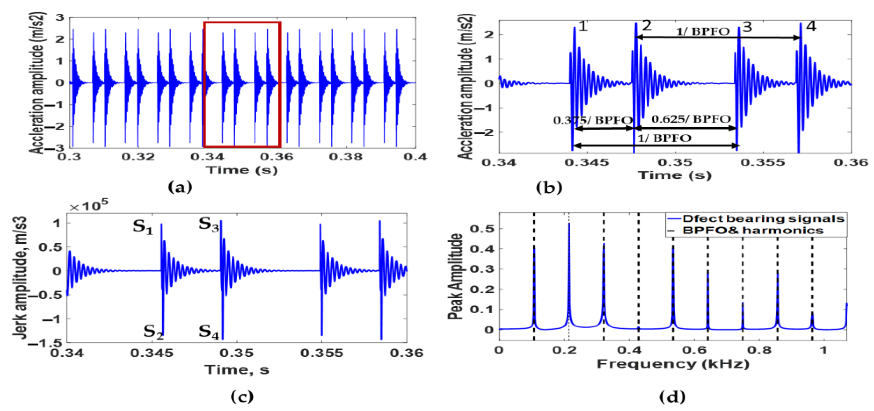
Figure 6 shows the simulation results for the modeled bearing with two dents located on its inner raceway by solving Equations (17)–(19) at a rotation speed of 1797 rpm. The dent used in the bearing model has a 0.17 mm diameter and 0.28 mm depth. The angle between the two dents is 15°, and the first dent is positioned at 270° from the positive x-axis. To increase the readability of the simulated acceleration signal shown in Figure 6a, the simulated acceleration signal in a period between 0.34 s and 0.36 s is enlarged, as shown in Figure 6b.
Figure 6a,b shows that 33 impulses are generated during 0.1 s due to the interaction between rolling elements and Dents 1 and 2. By observing the phase shift between impulses, it can be deduced that Impulses 1 and 3 are created due to the interaction of rolling elements with Dent 1, whereas rolling element interactions with Dent 2 generate Impulses 2 and 4. The time interval between Impulses 1 and 3 and Impulses 2 and 4 is found to be 6.17 ms, which is approximately equal to 1/BPFI, where BPFI is the ball bass frequency on the inner race. According to Igarashi et al. [63], the reciprocal of time delay (fτi) between defects for a rolling element bearing whose inner raceway has two defects can be calculated from Equation (21).
f τ o = φ o φ B P F I   &   B P F I = N b ( ω i ω c ) 2 π
where φo is the interval angle between rolling elements, and φ is the phase shift angle between two defects, which is equal to the remainder of the division of the angle between two defects by the interval angle between defects. By applying Equation (21) to the current case, the corresponding φ is found to be 15°, and the reciprocal of time delay is 432.12 Hz. Accordingly, the time difference between Impulses 1 and 2 is 2.31 ms (3/8 BPFI) and between impulses 2 and 3 is 3.86 ms (5/8 BPFI), which confirms the results of the simulated acceleration signal.
Figure 6c shows the simulated jerk signal of the bearing model with double dents on its inner race. Destressing actions occur when the rolling element enters the first and second dent, generating positive impulses s1 and s3. Meanwhile, negative impulses s2 and s4 are generated due to restressing at the exit of the rolling element from both dents. The time difference between Impulses s1 and s2 and between Impulses s3 and s4 is 98 µs. Based on the inner race, cage angular velocity, and outer raceway diameter, the diameter of the dents is calculated and found to be 0.17 mm.
In Figure 6d, we can see the simulated acceleration signal’s envelope spectrum. Peaks in the vibration amplitude are observed at frequencies that agree with the theoretical value of the inner race fault characteristics frequency (BPFI) and its harmonics. This result further proves the soundness of the developed bearing model with inner raceway defects. Furthermore, the maximum peaks are located at the second BPFI harmonics.

3.2. Simulation Results of Bearing with a Dent and Bump

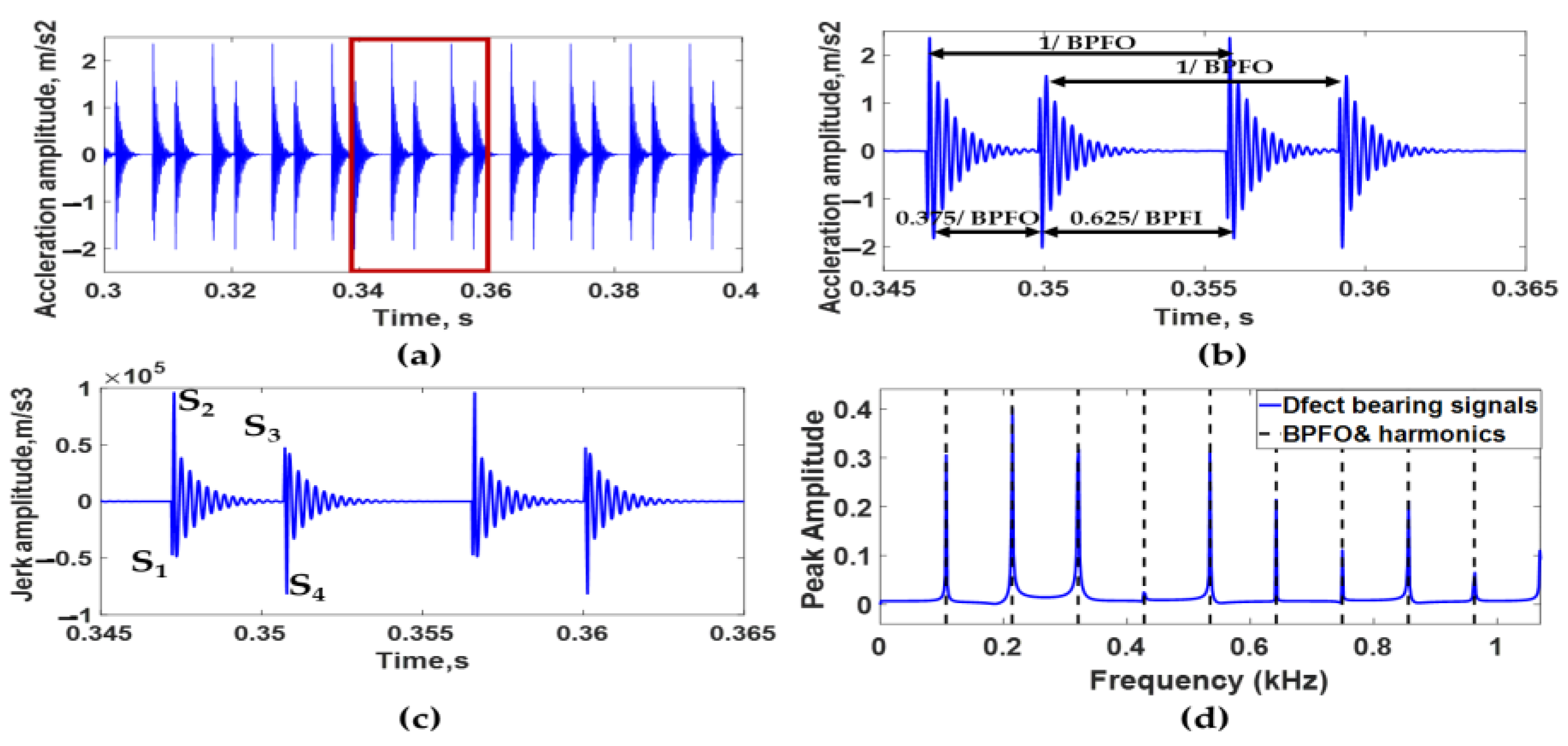
The vibration response of the ball bearing model having two different defects on its outer raceway is studied in the simulation environment by solving Equations (17)–(19). The first defect is a bump with a 0.17 mm diameter and 0.1 µm depth, while the other defect is a dent whose diameter and height are 0.17 mm, and 0 is Tom Bolton 27 mm, respectively. The phase angle between the two defects is 15°, and the location of the dent is the intersection between the raceway with a negative x-axis. The rotational speed is selected to be 1797 rpm. The results of the simulation trials are shown in Figure 7.
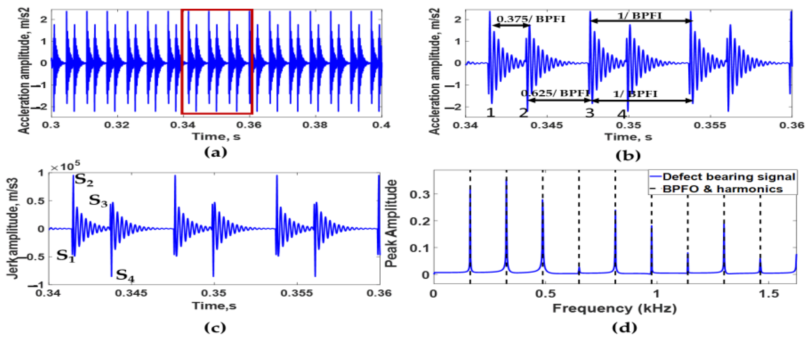
Figure 7a demonstrates that 21 impulses are generated from the interaction of rolling elements with the dent and bump. The shapes of impulses in enlarged acceleration signals shown in Figure 7b depict that bump and dent generate Impulses 1 and 3 and Impulses 2 and 4, respectively. Furthermore, the time delay between Impulses 1 and 3 and Impulses 2 and 4 is equal to 1/BPFO (9.3 ms). In addition, the time delays between Impulses 1 and 2 and between Impulses 2 and 3 are 3.5 ms (5/8BPFO) and 5.8 ms (5/8BPFO), respectively, which match Igarashi’s equation. This confirms the soundness of the bearing model in the case of multi-faults with different geometries and forms located on the outer race.
Figure 7c illustrates the simulated jerk signal of the bearing with dent and bump defects on its outer raceway. When the rolling element passes over the dent, two impulses s3 and s4 are generated from destressing and restressing actions. For the bump, Impulses s3 and s4 are induced during the passing of the rolling element over it. The time difference between Impulses s1 and s2 is found to be 97 µs, which is the same time difference between Impulses s3 and s4. Based on the cage angular velocity and the diameter of the outer raceway, the dent and bump diameters are calculated and found equal to 0.17 mm.
Figure 7d shows the envelope spectrum analysis of the simulated acceleration signal, which is similar to that obtained from the acceleration signal of a bearing with double dents on its outer raceway. The peaks located at the frequencies match the theoretical value of BPFO and its harmonics, which further confirms the accuracy of the bearing model results.
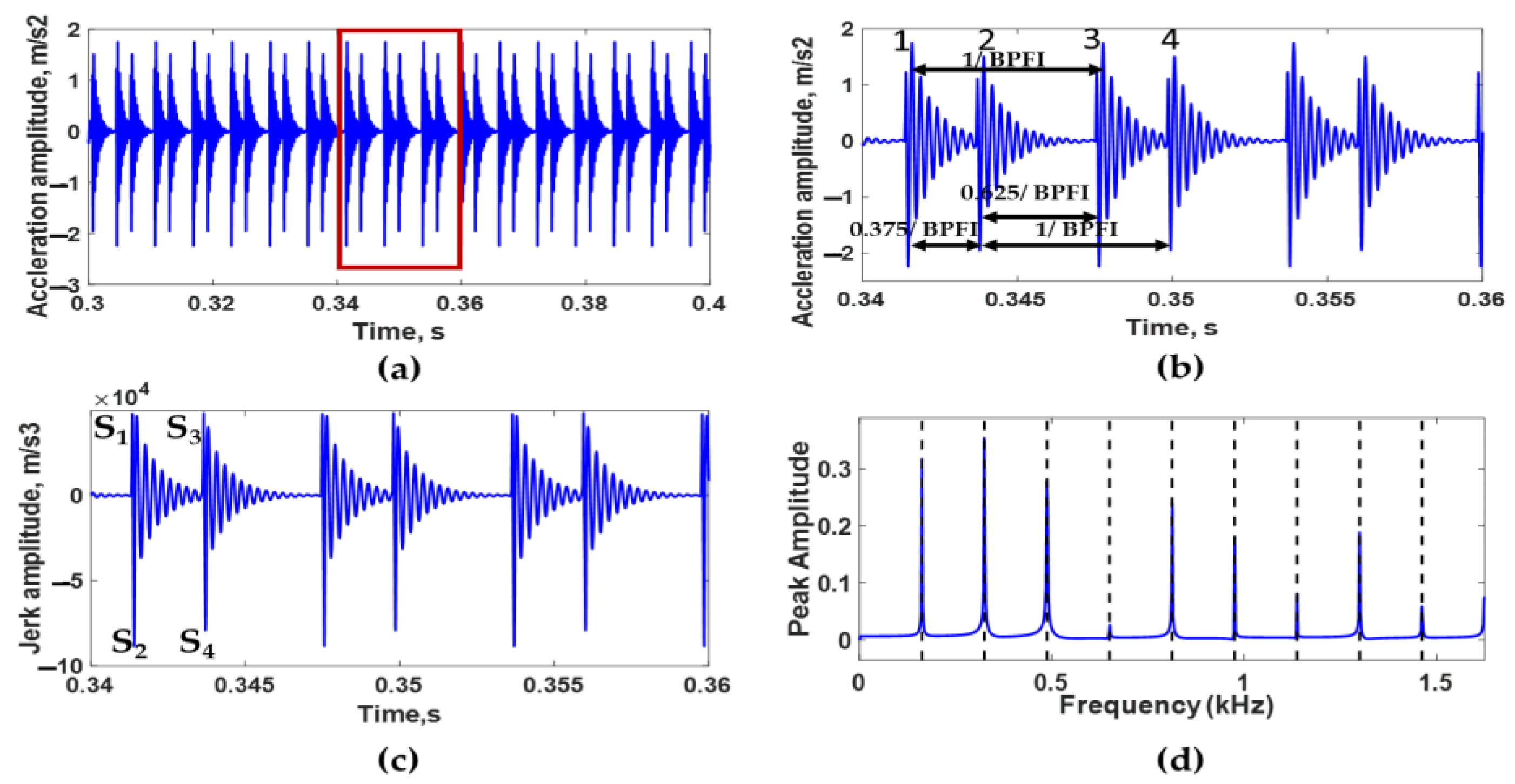
Figure 8 shows the simulation results of the bearing model with successive bump and dent defects on its inner raceway by solving Equations (17)–(19) at a rotation speed of 1797 rpm. The bump used in the simulation has a 0.17 mm diameter and 0.1 µm height, while the dent has a 0.17 mm diameter and 0.28 mm depth. The angle between the two modeled defects is 15°, and the bump is positioned at 270° from the positive x-axis. To increase the visibility of the simulated acceleration signal shown in Figure 8a, the simulated acceleration signal in a period between 0.34 s and 0.36 s is demonstrated in Figure 8b.
When the rolling elements pass over the bump and dent, they generate 32 impulses during a 0.1 ms period, as shown in Figure 8a. The generated bearing signal in the time domain shown in Figure 8b indicates that Impulses 1 and 3 are created due to the passing of rolling elements over the bump, whereas rolling elements passing over the dent generate Impulses 2 and 4. Furthermore, the duration between Impulses 1 and 3 and Impulses 2 and 4 is around 6.17 ms, which is equal to 1/BPFI. Furthermore, the time delay between Impulses 1 and 2 and Impulses 2 and 3 is 2.32 ms (5/8BPFI) and 3.85 ms (3/8BPFI), respectively. These values are consistent with those calculated from Equation (21).
Figure 8c illustrates the simulation jerk signal of a bearing with a bump and dent on its inner race. As the ball passes over the bump negative impulse s1 generates first due to stressing followed by a positive impulse s2, which results from destressing. As the ball passes over the dent, destressing followed by restressing generates a positive impulse s3 and a negative impulse s4, respectively. The time difference between Impulses s1 and s2 and between Impulses s3 and s4 is 98 µs. Based on the inner race, the cage angular velocity, and the outer raceway diameter, the diameter of the bump and dent is 0.17 mm.
The envelope spectrum of the simulated acceleration signal is given in Figure 8d. The vibration peaks occur at frequencies that match the theoretical inner race fault characteristics frequency (BPFI) and its harmonics. In addition, the frequency at which the maximum peak locate is coincident with the second BPFI harmonics.
During the actual operation of the rolling element bearing, multiple defects may arise at different sizes and phase angles on the inner or outer raceway. In the case of small phase angles, this may affect the interpretation of faults of a measured bearing signal. In addition, the number of dents and bumps is an influential parameter to consider while analyzing the measured vibration signal to properly detect and identify faults and their locations on rolling bearings. The following sections address the influence of each parameter on the obtained vibration response of the bearing model.

3.3. Effect of Phase Angle between Defects

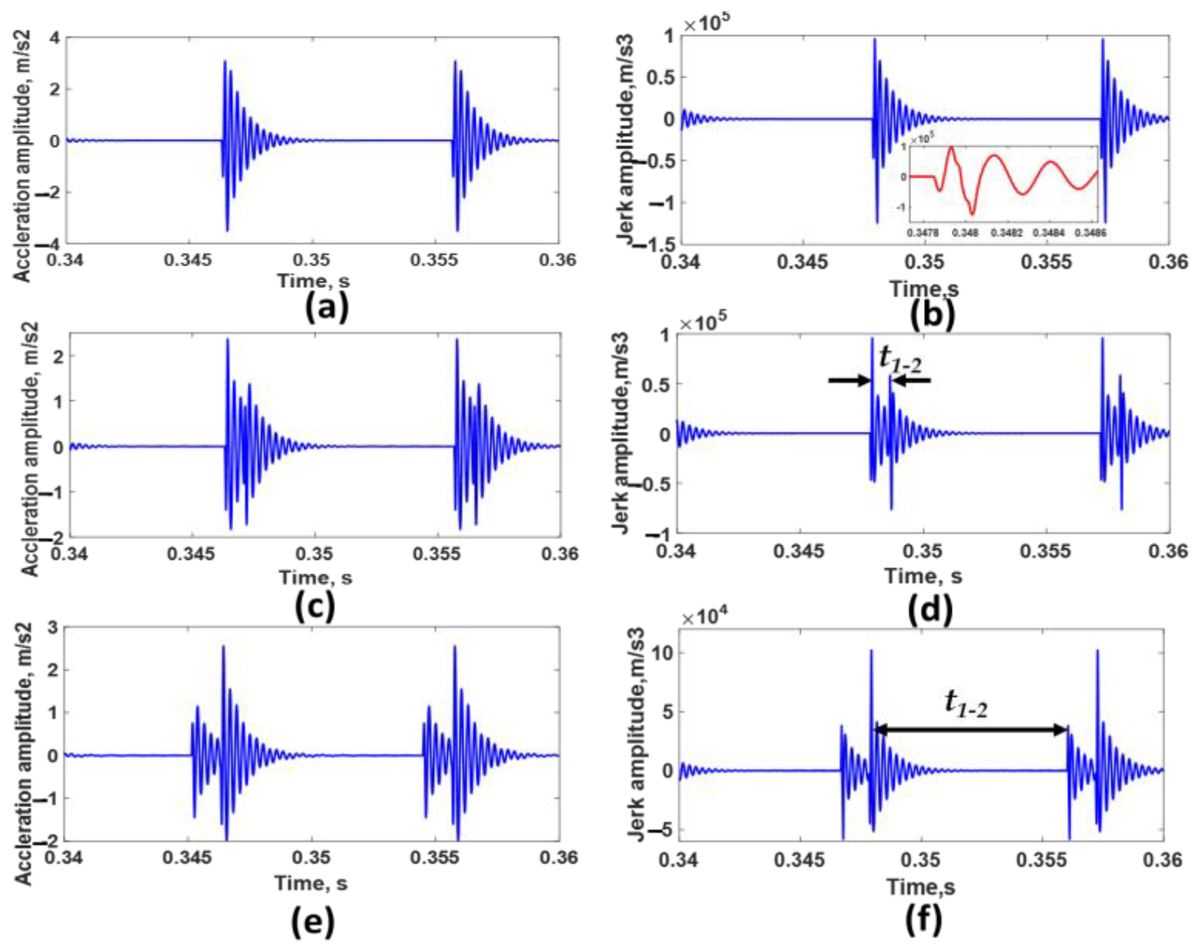
A ball bearing model with bump and dent defects on its outer raceway is considered for studying the effect of changing the angle between defects on the vibration response of the bearing. The bump has a diameter of 0.17 mm and height of 0.1 µm, while the dent has a 0.17 mm diameter and 0.27 mm depth. The bump location is the intercept between the x-axis and outer raceway at the heavily loaded zone. The angle values between the two defects are varied from 0.415° to 34.8° (radial distance from d to 84 d). The bearing model is made to run at 1797 rpm. The simulation results are given in Figure 9.
In Figure 9a,b, the two transient impulses generated during the passing of the rolling bearing over the two defects are merged due to the small value of the angle between defects (0.415°). Hence, it is difficult to identify the presence of double defects by relying only on the interpretation of the acceleration signal. By differentiation, jerk-induced vibrations due to the entrance and exit event of the bump and dent are clearly noticed. Therefore, it is necessary to use a jerk signal for recognizing the occurrence of double defects, especially when the angle between defects is small.
Figure 10a indicates the relationship of the time interval between the ending and beginning of destressing impulses t1–2 measured from the jerk signal and the angle between the two defects. It can be seen that t1–2 increases linearly with the increasing angle between defects, and this is for an angle less than the angle between two adjustment balls. Therefore, the angle between the two defects β can be calculated from Equation (22) as follows:
β = t 1 2 f b f o φ o
The relationship between the peak amplitudes of the acceleration signal at the second BPFO harmonics and the angle between the two defects is shown in Figure 10b. Equation (23), derived by nonlinear regression, describes the mathematical relationship between the second BPFO harmonic peak amplitudes (Abfo) and the angle between the bump and dent, which provides a guide to evaluating the angle between defects.
A b f o = 0.395 + 0.249   c o s     ( 2 π β / φ o ) + 0.029 s i n ( 2 π β / φ o )

3.4. Effect of Defect Size

A ball bearing model with bump and dent defects on its outer raceway is considered for studying the effect of changing the defect diameters on the vibration response of the bearing. The bump has a height of 0.1 µm, while the dent has a 0.27 mm depth. The bump location is the intercept between the x-axis and outer raceway at the heavily loaded zone, and the angle between defects is 15°. The defect diameter values vary from 0.17 mm to 2.5 mm. The bearing model is made to run at 1797 rpm. The simulation results are given in Figure 11.
Figure 11a,b depicts that the increase in defect width leads to an increase in acceleration and jerk amplitude. Figure 11c,d illustrates that as the defect width increases, the time difference between the entering impulse jerk and the exiting impulse jerk increases, which can be used as an indication of the defect width.
Figure 12a indicates the relationship between acceleration RMS values and defect width. It is visible that the RMS increases logarithmically as the defect width increases. The relationship between the maximum peak amplitude at the second BPFO harmonics of the envelope spectrum of the acceleration signal of the defective bearing is shown in Figure 12. It is visible that the peak amplitude is increased logarithmically with an increase in the defect width. Equation (24), derived by nonlinear regression, describes the mathematical relationship between the second BPFO harmonic peak amplitudes (Abfo) and the defect width, which provides a guide to evaluating the defect width.
A b f o = 3.18143 ln d + 7.0161

3.5. Effect of Number of Defects

To investigate the effect of het number of defects on the bearing vibration characteristics, the simulated results for a bearing with multiple bumps and dents (four, six, and eight defects) in repeated sequence on its outer raceway are obtained by solving dynamic Equations (17)–(19) at a rotation speed of 1797 rpm. In this simulation, all defects have a 0.17 mm diameter, while the depth of the dent is 0.28 mm, and the height of the bump is 0.1 µm. The phase angle between every two defects is 5°; the location of the first defect is a bump, and it is selected to be coincident with the negative x-axis. The simulation results are shown in Figure 13.
From Figure 13, if the angle between every two defects is large enough to prevent the merging of impulses, and given that the angle between the first defect and the last one is smaller than the interval angle between rolling elements, then the passing of the rolling bearing over the defects generates a number of acceleration impulses equal to the number of defects. Due to the difficulty to recognize each impulse and identify its number, and the time interval between each impulse, it is necessary to use jerk signals. As clear from the jerk signals, the number of stressing and destressing shocks during the time interval between the two consecutive rolling elements is equal to double the number of defects, and it is easy from the sign of every two repeated shocks to determine each defect type. In addition, it is visible that the time interval between the two consequences of destressing or stressing shocks is constant, and this is due to the constant angle between each.
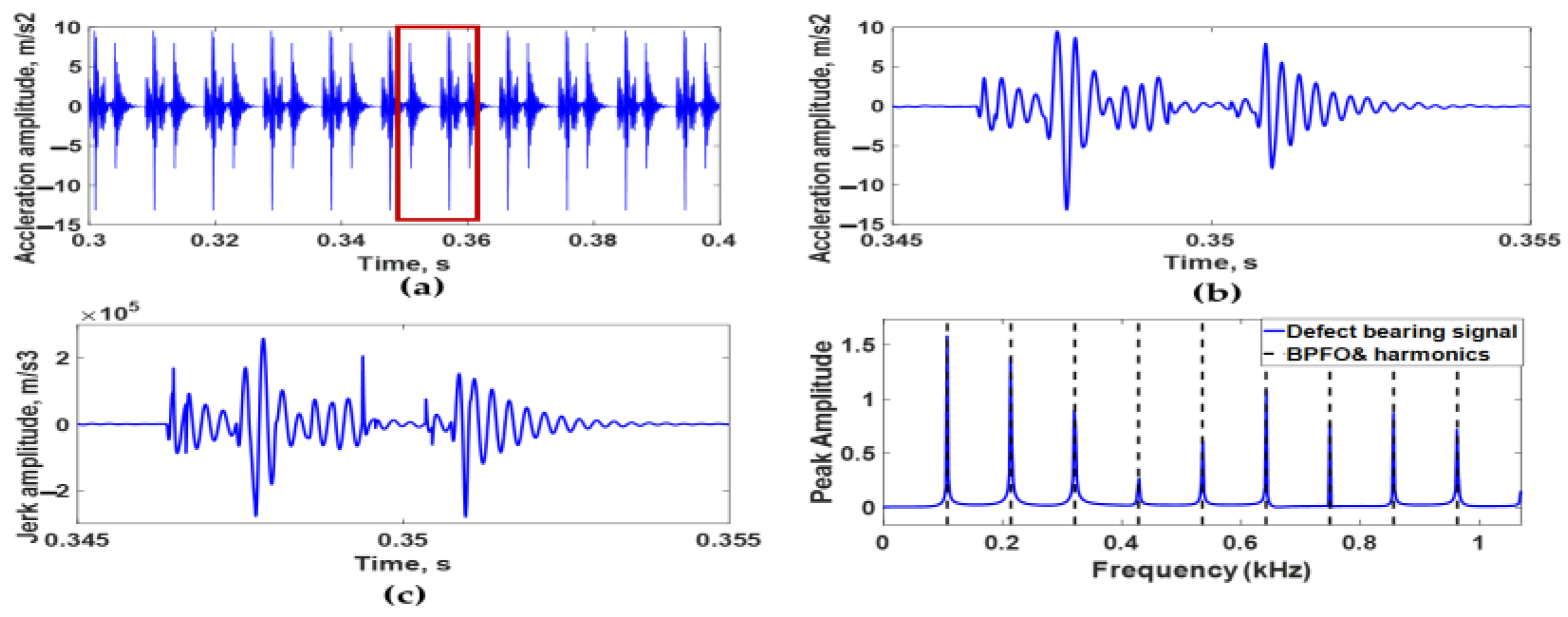
Due to the random nature of the debris particle size and motion, it may cause in some cases a randomly sized bump and dent located arbitrarily on a small area of the bearing raceways. Figure 14 represents the dynamic response of a ball bearing with seven randomly distributed dent and bump defects on its outer race surface. These defects have different diameters and depths/heights. In addition, the angles between each adjacent defect randomly vary. From acceleration signals and its envelope spectrum, it is easy to conclude that the bearing is defective on its outer race. However, it is difficult to determine the number of defects and the angle between them, as well as the type and diameter of each defect, without analysis of the bearing jerk signal.

4. Experimental Validation

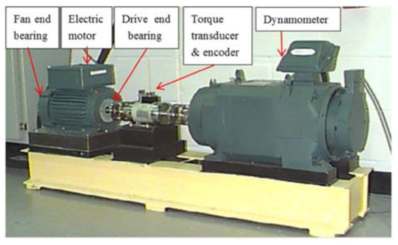
The verification of the proposed ball bearing dynamic model is conducted using defective bearing test data provided by the Bearings Data Center at Case Western Reserve University (CWRU) [65] using the test rig shown in Figure 15. A 2 hp electric motor is used to drive a shaft on which torque is applied via a load motor. Individual localized faults are generated at the surfaces of the inner raceway, outer raceway, and balls of motor bearings via electrical discharge machining (EDM). Vibration acceleration data are measured at locations near to and far off the motor bearings at a 12 kHz sampling frequency. The results of vibration characteristics for each faulty bearing with different fault sizes and locations are used as a benchmark. Hence, comparisons between the advanced fault identification methods can be easily held.
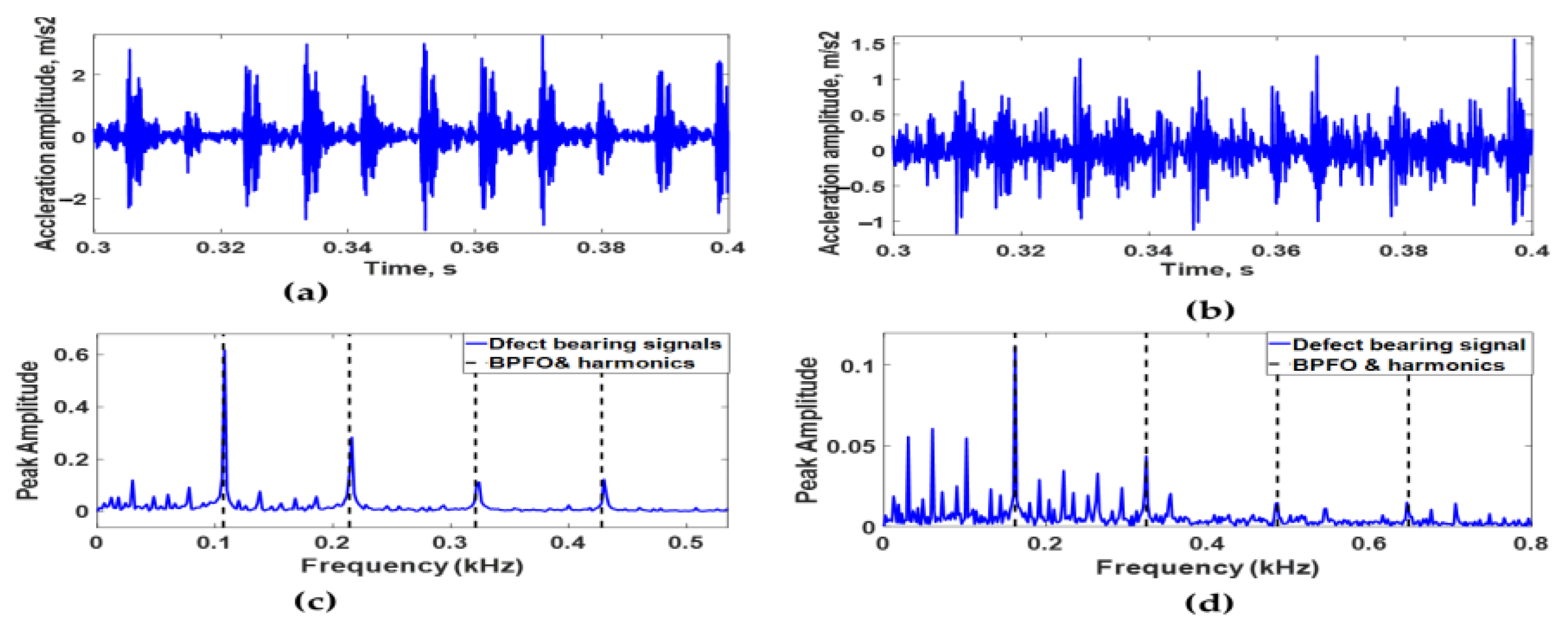
In this study, the vibration data obtained from a bearing defect in the motor drive end bearing in the two different cases are used in the proposed model validation. In the first case, the defect is located at the bearing outer raceway, while the second case has the defect located in the inner race. The bearing defect in both cases has a 0.007-inch (0.17 mm) diameter and 0.011-inch (0.28 mm) depth and is located at the heavily loaded zone. The bearing is a 6205-2RS JEM SKF deep-groove ball bearing. The operating condition of the bearing is that the motor is running at approximately 1797 rpm under zero motor load. The vertical vibration data at the motor driving end were collected at sampling frequencies of 12 kHz. The experimental vertical acceleration signal and simulated acceleration signal for the two cases are depicted in Figure 16.
Experimental acceleration signals of ball bearings have a defect on the outer raceway in one case and the inner raceway in other cases, as shown in Figure 16a,b. It is clear that periodic impulses occur due to the passing of rolling elements above a dent in the two cases. In addition, the average time delay between two consecutive impulses is 9.3 ms when the dent is located in the outer raceway. However, 69 ms is the average time delay between the acceleration signals of the bearing that has a dent in the inner raceway. In addition, Figure 16c,d indicates the envelope spectrum of experimental signals in both cases. It is obvious that the peak amplitudes occur at ball bass frequency on the outer race, which equals 107.9 HZ, and it is harmonic when the dent is located in the outer raceway. Meanwhile, in the case of the dent located in the inner raceways, the highest peak amplitude occurs at 162 Hz, which is equal to the ball bass frequency on the inner race. In addition, the other beaks occur at the harmonics.
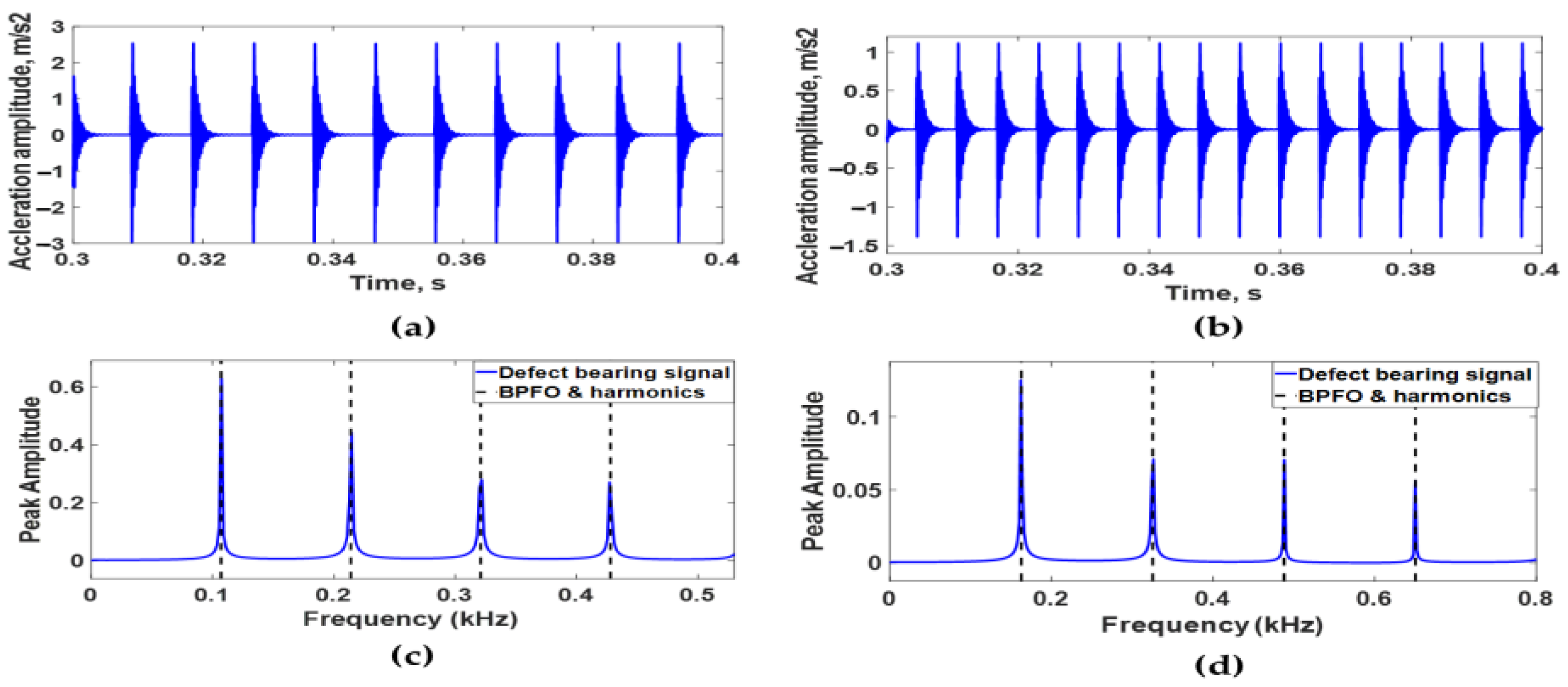
Figure 17a,b demonstrates the simulation results of the ball bearing model in two cases: one with a dent on the outer raceway, and the other with a dent on the inner raceway. The time delay between impulses in the signals of the two cases is 92 ms and 62 ms, respectively. The envelope spectra of simulated acceleration signals of the two model cases are shown in Figure 17c,d. When the dent is located in the outer raceway, the peak amplitudes are clearly at the ball bass frequency of 108 HZ, and this is harmonic. However, the maximum peak amplitude of the dent in the inner raceways occurs at 161.9 Hz. The other beaks can be found in the harmonics of this one. These show that the simulated results are the same as the experimental ones, which validates the proposed dynamic bearing model for a single dent mode of fault.

5. Conclusions

A nonlinear dynamic model of a deep-groove ball bearing was developed to investigate the effect of two different multipoint defects located on the same raceway on the bearing vibration response. Contrary to most previous research, a dent and bump, with hemispherical shapes, were selected to represent two common point defects generated by mechanisms of adhesion of debris in contaminated lubricants and by spalling of subsurface layers due to fatigue. This 6-DOF model considered the flexibility of bearing shaft and house, the damping of lubricant film, the effect of bearing preload, the inertia effect of rolling element, time-varying compliance, and time-varying displacement produced due to defects. The effect of defect size, the angle between defects, and defect number on vibration characteristics of bearing in the time domain and frequency domain were considered to obtain a more accurate bearing fault detection method. The results of this study can be summarized as follows:
  • The vibration pattern of faulty bearings is greatly influenced by the defect type, defect size, and angle between defects.
  • The envelope spectrum analysis of the vibration acceleration signal showed that the amplitude of BPFO second harmonic peaks decreases as the phase angle between defects is increased until half interval angle between rolling elements, and then the amplitude increases with the increase in angle. Furthermore, the vibration amplitude of the BPFO second harmonics increases with the increase in defect size.
  • It is challenging from the analysis of acceleration signals only to predict the number of defects, the angle between each adjacent defect, the size of each defect, and the type of each defect. This difficulty is due to interference of transient impulses produced from sequential defects. To solve this difficulty, it is recommended to use jerk signal analysis.
  • The model results for a single defect were verified using bearing test data provided by CWRU in which the EDM process was used to induce localized faults on the raceway with similar spherical geometries and diameters to the modeled faults.
  • The developed model did not consider the effect of lubricant film stiffness, internal clearance, slipping of rolling elements, or the combined effect of change of rotating speed and radial load, which has an effect on bearing vibration response.
  • Future work will focus on simulation and experimental work on bearing with multiple defects, considering the combined influence of internal radial clearance and oil film lubrication characteristics on the vibration response.

Author Contributions

Conceptualization, M.M.A., W.K.-E., J.Y., and M.G.A.N.; methodology, M.M.A., W.K.-E., J.Y. and M.G.A.N.; software, M.M.A. and M.G.A.N.; validation, W.K.-E. and J.Y.; investigation, J.Y.; data curation, M.M.A., W.K.-E. and J.Y.; data curation, W.K.-E., J.Y. and M.G.A.N.; writing—original draft preparation, M.M.A.; writing—review & editing, W.K.-E., J.Y. and M.G.A.N.; visualization, W.K.-E. and M.G.A.N.; project administration, M.G.A.N. All authors have read and agreed to the published version of the manuscript.

Funding

This research received no external funding.

Data Availability Statement

Not applicable.

Conflicts of Interest

The authors declare no conflict of interest.

References

  1. Nassef, M.G.A.; Hussein, T.M.; Mokhiamar, O. An adaptive variational mode decomposition based on sailfish optimization algorithm and Gini index for fault identification in rolling bearings. Measurement 2021, 173, 108514. [Google Scholar] [CrossRef]
  2. Liu, J.; Xu, Y.; Pan, G. A combined acoustic and dynamic model of a defective ball bearing. J. Sound Vib. 2021, 501, 116029. [Google Scholar] [CrossRef]
  3. Georgoulas, G.; Loutas, T.; Stylios, C.D.; Kostopoulos, V. Bearing fault detection based on hybrid ensemble detector and empirical mode decomposition. Mech. Syst. Signal Process. 2013, 41, 510–525. [Google Scholar] [CrossRef]
  4. Moazen-Ahmadi, A.; Howard, C.Q. A defect size estimation method based on operational speed and path of rolling elements in defective bearings. J. Sound Vib. 2016, 385, 138–148. [Google Scholar] [CrossRef]
  5. Liu, J.; Shao, Y. Overview of dynamic modelling and analysis of rolling element bearings with localized and distributed faults. Nonlinear Dyn. 2018, 93, 1765–1798. [Google Scholar] [CrossRef]
  6. Ashtekar, A.; Sadeghi, F.; Stacke, L.-E. Surface defects effects on bearing dynamics. Proc. Inst. Mech. Eng. Part J J. Eng. Tribol. 2010, 224, 25–35. [Google Scholar] [CrossRef]
  7. Sawalhi, N.; Randall, R. Vibration response of spalled rolling element bearings: Observations, simulations and signal processing techniques to track the spall size. Mech. Syst. Signal Process. 2011, 25, 846–870. [Google Scholar] [CrossRef]
  8. Jiang, Y.; Huang, W.; Luo, J.; Wang, W. An improved dynamic model of defective bearings considering the three-dimensional geometric relationship between the rolling element and defect area. Mech. Syst. Signal Process. 2019, 129, 694–716. [Google Scholar] [CrossRef]
  9. Kumbhar, S.G.; Sudhagar, E.; Desavale, R. An overview of dynamic modeling of rolling-element bearings. Noise Vib. Worldw. 2021, 52, 3–18. [Google Scholar] [CrossRef]
  10. Boudiaf, A.; Djebala, A.; Bendjma, H.; Balaska, A.; Dahane, A. A summary of vibration analysis techniques for fault detection and diagnosis in bearing. In Proceedings of the 2016 8th International Conference on Modelling, Identification and Control, ICMIC 2016, Algiers, Algeria, 15–17 November 2016; pp. 37–42. [Google Scholar] [CrossRef]
  11. El-Thalji, I.; Jantunen, E. A summary of fault modelling and predictive health monitoring of rolling element bearings. Mech. Syst. Signal Process. 2015, 60, 252–272. [Google Scholar] [CrossRef]
  12. Li, W.; Qiu, M.; Zhu, Z.; Jiang, F.; Zhou, G. Fault diagnosis of rolling element bearings with a spectrum searching method. Meas. Sci. Technol. 2017, 28, 095008. [Google Scholar] [CrossRef]
  13. Al Bugharbee, H.; Trendafilova, I. A new methodology for fault detection in rolling element bearings using singular spectrum analysis. MATEC Web Conf. 2018, 148, 14002. [Google Scholar] [CrossRef] [Green Version]
  14. Cheng, Y.; Zou, D.; Zhang, W.; Wang, Z. A Hybrid Time-Frequency Analysis Method for Railway Rolling-Element Bearing Fault Diagnosis. J. Sens. 2019, 2019, 8498496. [Google Scholar] [CrossRef]
  15. Cai, J.; Xiao, Y. Time-frequency analysis method of bearing fault diagnosis based on the generalized S transformation. J. Vibroeng. 2017, 19, 4221–4230. [Google Scholar] [CrossRef] [Green Version]
  16. Albezzawy, M.N.; Nassef, M.G.A.; Elsayed, E.S.; Elkhatib, A. Early Rolling Bearing Fault Detection Using a Gini Index Guided Adaptive Morlet Wavelet Filter. In Proceedings of the 2019 IEEE 10th International Conference on Mechanical and Aerospace Engineering (ICMAE), Brussels, Belgium, 22–25 July 2019; pp. 314–322. [Google Scholar] [CrossRef]
  17. Klepka, A. Wavelet based signal demodulation technique for bearing fault detection. Mech. Mech. Eng. 2011, 15, 63–71. [Google Scholar]
  18. Wang, D.; Sun, S.; Tse, P.W. A general sequential Monte Carlo method based optimal wavelet filter: A Bayesian approach for extracting bearing fault features. Mech. Syst. Signal Process. 2015, 52–53, 293–308. [Google Scholar] [CrossRef]
  19. Zhou, F.; Chen, J.; He, J.; Bi, G.; Zhang, G.; Li, F. Application of cyclostationary signal processing with wavelet filtering in rolling element bearing fault diagnosis. Zhendong Yu Chongji J. Vib. Shock 2006, 25, 91–93. [Google Scholar]
  20. Shi, H.; Shang, Y. Initial Fault Diagnosis of Rolling Bearing Based on Second-Order Cyclic Autocorrelation and DCAE Combined with Transfer Learning. IEEE Trans. Instrum. Meas. 2022, 71, 3503818. [Google Scholar] [CrossRef]
  21. Kumar, S.S.; Mohan, N.; Poornachandran, P.; Soman, K.P. Condition monitoring in roller bearings using cyclostationary features. In Proceedings of the Third International Symposium on Women in Computing and Informatics, Kochi, India, 10–13 August 2015; pp. 690–697. [Google Scholar] [CrossRef]
  22. Wang, S.; Niu, P.; Guo, Y.; Wang, F.; Li, W.; Shi, H.; Han, S. Early diagnosis of bearing faults using decomposition and reconstruction stochastic resonance system. Measurement 2020, 158, 107709. [Google Scholar] [CrossRef]
  23. Gong, T.; Yuan, X.; Wang, X.; Yuan, Y.; Zhang, B. Fault diagnosis for rolling element bearing using variational mode decomposition and l1 trend filtering. Proc. Inst. Mech. Eng. Part O J. Risk Reliab. 2020, 234, 116–128. [Google Scholar] [CrossRef]
  24. Liu, H.; Xiang, J. Kernel regression residual signal-based improved intrinsic time-scale decomposition for mechanical fault detection. Meas. Sci. Technol. 2019, 30, 015107. [Google Scholar] [CrossRef]
  25. Yakout, M.; Nassef, M.G.A.; Backar, S. Effect of clearances in rolling element bearings on their dynamic performance, quality and operating life. J. Mech. Sci. Technol. 2019, 33, 2037–2042. [Google Scholar] [CrossRef]
  26. Patil, A.P.; Mishra, B.K.; Harsha, S.P. Vibration based modelling of acoustic emission of rolling element bearings. J. Sound Vib. 2020, 468, 115117. [Google Scholar] [CrossRef]
  27. Gupta, P.K. Advanced Dynamics of Rolling Elements; Springer: New York, NY, USA, 1984. [Google Scholar] [CrossRef]
  28. Gupta, P.K. Dynamics of Rolling-Element Bearings Part IV: Ball Bearing Results. J. Tribol. 1979, 101, 319–326. [Google Scholar] [CrossRef]
  29. Ghaisas, N.; Wassgren, C.R.; Sadeghi, F. Cage Instabilities in Cylindrical Roller Bearings. J. Tribol. 2004, 126, 681–689. [Google Scholar] [CrossRef]
  30. Jang, G.H.; Jeong, S.W. Analysis of a Ball Bearing with Waviness Considering the Centrifugal Force and Gyroscopic Moment of the Ball. J. Tribol. 2003, 125, 487–498. [Google Scholar] [CrossRef]
  31. Sopanen, J.; Mikkola, A. Dynamic model of a deep-groove ball bearing including localized and distributed defects. Part 1: Theory. Proc. Inst. Mech. Eng. Part K J. Multi-Body Dyn. 2003, 217, 201–211. [Google Scholar] [CrossRef]
  32. Ji, P.; Gao, Y.; Ma, F.; An, Q. Influences of roller diameter error on contact stress for cylindrical roller bearing. Proc. Inst. Mech. Eng. Part J J. Eng. Tribol. 2015, 229, 689–697. [Google Scholar] [CrossRef]
  33. Liu, J.; Yan, Z.; Shao, Y. An investigation for the friction torque of a needle roller bearing with the roundness error. Mech. Mach. Theory 2018, 121, 259–272. [Google Scholar] [CrossRef]
  34. Zhenhuan, Y.; Liqin, W. Effects of axial misalignment of rings on the dynamic characteristics of cylindrical roller bearings. Proc. Inst. Mech. Eng. Part J J. Eng. Tribol. 2016, 230, 525–540. [Google Scholar] [CrossRef]
  35. Xing, Y.; Xu, H.; Pei, S.; Zhang, X.; Chang, W. Mechanical analysis of spherical roller bearings due to misalignments between inner and outer rings. Proc. Inst. Mech. Eng. Part C J. Mech. Eng. Sci. 2017, 231, 3250–3262. [Google Scholar] [CrossRef]
  36. Patel, V.N.; Tandon, N.; Pandey, R.K. Vibration studies of dynamically loaded deep groove ball bearings in presence of local defects on races. Procedia Eng. 2013, 64, 1582–1591. [Google Scholar] [CrossRef]
  37. Ghafari, S.H.; Golnaraghi, F.; Ismail, F. Effect of localized faults on chaotic vibration of rolling element bearings. Nonlinear Dyn. 2008, 53, 287–301. [Google Scholar] [CrossRef]
  38. Mattar, A.H.A.; Sayed, H.; Younes, Y.K.; El-Mongy, H.H. Experimental Verification and Nonlinear Dynamic Response Analysis of a Rolling Element Bearing with Localized Defects. J. Fail. Anal. and Preven. 2022, 22, 1753–1770. [Google Scholar] [CrossRef]
  39. Nakhaeinejad, M.; Bryant, M.D. Dynamic Modeling of Rolling Element Bearings with Surface Contact Defects Using Bond Graphs. J. Tribol. 2011, 133, 011102. [Google Scholar] [CrossRef]
  40. Patil, M.S.; Mathew, J.; Rajendrakumar, P.K.; Desai, S. A theoretical model to predict the effect of localized defect on vibrations associated with ball bearing. Int. J. Mech. Sci. 2010, 52, 1193–1201. [Google Scholar] [CrossRef]
  41. Liu, J.; Shao, Y.; Zhu, W.D. A New Model for the Relationship Between Vibration Characteristics Caused by the Time-Varying Contact Stiffness of a Deep Groove Ball Bearing and Defect Sizes. J. Tribol. 2015, 137, 031101. [Google Scholar] [CrossRef]
  42. Singh, S.; Köpke, U.G.; Howard, C.Q.; Petersen, D. Analyses of contact forces and vibration response for a defective rolling element bearing using an explicit dynamics finite element model. J. Sound Vib. 2014, 333, 5356–5377. [Google Scholar] [CrossRef]
  43. Li, D.; Kang, Y.S. Simulation and Experimental Validation of Tapered Roller Bearing Vibration Induced by Geometrical Imperfection on Cup Raceway. In Proceedings of the ASME 2014 International Design Engineering Technical Conferences and Computers and Information in Engineering Conference. Volume 8: 26th Conference on Mechanical Vibration and Noise, Buffalo, NY, USA, 17–20 August 2014. [Google Scholar] [CrossRef]
  44. Liu, J.; Wu, H.; Shao, Y. A theoretical study on vibrations of a ball bearing caused by a dent on the races. Eng. Fail. Anal. 2018, 83, 220–229. [Google Scholar] [CrossRef]
  45. Shi, Z.; Liu, J.; Chen, Z.; Shao, Y. Vibration Analysis of a Roller Bearing with a Bump Defect. In Proceedings of the ASME 2018 International Design Engineering Technical Conferences and Computers and Information in Engineering Conference. Volume 8: 30th Conference on Mechanical Vibration and Noise, Quebec City, QC, Canada, 26–29 August 2018. [Google Scholar] [CrossRef]
  46. Cerrada, M.; Sánchez, R.-V.; Li, C.; Pacheco, F.; Cabrera, D.; de Oliveira, J.V.; Vásquez, R.E. A review on data-driven fault severity assessment in rolling bearings. Mech. Syst. Signal Process. 2018, 99, 169–196. [Google Scholar] [CrossRef]
  47. McFadden, P.D.; Smith, J.D. The vibration produced by multiple point defects in a rolling element bearing. J. Sound Vib. 1985, 98, 263–273. [Google Scholar] [CrossRef]
  48. Zhang, X.; Yan, C.; Liu, Y.; Yan, P.; Wang, Y.; Wu, L. Dynamic Modeling and Analysis of Rolling Bearing with Compound Fault on Raceway and Rolling Element. Shock Vib. 2020, 2020, 8861899. [Google Scholar] [CrossRef]
  49. Gao, X.; Yan, C.; Liu, Y.; Yan, P.; Yang, J.; Wu, L. A 4-DOF dynamic model for ball bearing with multiple defects on raceways. Proc. Inst. Mech. Eng. Part K J. Multi-Body Dyn. 2021, 235, 3–18. [Google Scholar] [CrossRef]
  50. Sawalhi, N.; Randall, R. Simulating gear and bearing interactions in the presence of faults: Part I. The combined gear bearing dynamic model and the simulation of localised bearing faults. Mech. Syst. Signal Process. 2008, 22, 1924–1951. [Google Scholar] [CrossRef]
  51. Cui, L.; Zhang, Y.; Zhang, F.; Zhang, J.; Lee, S. Vibration response mechanism of faulty outer race rolling element bearings for quantitative analysis. J. Sound Vib. 2016, 364, 67–76. [Google Scholar] [CrossRef]
  52. Ashtekar, A.; Sadeghi, F.; Stacke, L.-E. A New Approach to Modeling Surface Defects in Bearing Dynamics Simulations. J. Tribol. 2008, 130, 041103. [Google Scholar] [CrossRef]
  53. Morales-Espejel, G.E.; Gabelli, A. Damage Mechanisms of Indentations in Raceways of Rolling Bearings. 2012. Available online: http://evolution.skf.com/damage-mechanisms-of-indentations-in-raceways-of-rolling-bearings/ (accessed on 26 September 2022).
  54. Harris, T.A.; Kotzalas, M.N. Rolling Bearing Analysis Essential Concepts of Bearing Technology; Wiley: New York, NY, USA, 2007. [Google Scholar]
  55. Tadina, M.; Boltežar, M. Improved model of a ball bearing for the simulation of vibration signals due to faults during run-up. J. Sound Vib. 2011, 330, 4287–4301. [Google Scholar] [CrossRef]
  56. Liu, Y.; Chen, Z.; Li, Y.; Zhai, W. Dynamic investigation and alleviative measures for the skidding phenomenon of lubricated rolling bearing under light load. Mech. Syst. Signal Process. 2022, 184, 109685. [Google Scholar] [CrossRef]
  57. Antaluca, E.; Nélias, D. Contact Fatigue Analysis of a Dented Surface in a Dry Elastic–Plastic Circular Point Contact. Tribol. Lett. 2008, 29, 139–153. [Google Scholar] [CrossRef]
  58. Johnson, K.L. Contact Mechanics, 1st ed.; Cambridge University Press: London, UK, 1985. [Google Scholar]
  59. Vakharia, V.; Gupta, V.K.; Kankar, P.K. Nonlinear dynamic analysis of ball bearings due to varying number of balls and centrifugal force. Mech. Mach. Sci. 2015, 21, 1831–1840. [Google Scholar] [CrossRef]
  60. Cheng, H.; Zhang, Y.; Lu, W.; Yang, Z. Research on ball bearing model based on local defects. SN Appl. Sci. 2019, 1, 1219. [Google Scholar] [CrossRef] [Green Version]
  61. Yan, P.; Yan, C.; Wang, K.; Wang, F.; Wu, L. 5-DOF Dynamic Modeling of Rolling Bearing with Local Defect considering Comprehensive Stiffness under Isothermal Elastohydrodynamic Lubrication. Shock Vib. 2020, 2020, 9310278. [Google Scholar] [CrossRef]
  62. Xu, M.; Feng, G.; He, Q.; Gu, F.; Ball, A. Vibration Characteristics of Rolling Element Bearings with Different Radial Clearances for Condition Monitoring of Wind Turbine. Appl. Sci. 2020, 10, 4731. [Google Scholar] [CrossRef]
  63. Igarashi, T.; Kato, J. Studies on the vibration and sound of defective rolling bearings. Bull. JSME 1985, 28, 492–499. [Google Scholar] [CrossRef]
  64. Ismail, M.A.A.; Klausen, A. Multiple Defect Size Estimation of Rolling Bearings using Autonomous Diagnosis and Vibrational Jerk. In Proceedings of the 7th World Conference on Structural Control and Monitoring, Qingdao, China, 22–25 July 2018. [Google Scholar]
  65. Bearing Data Center. Available online: https://engineering.case.edu/bearingdatacenter (accessed on 26 July 2022).
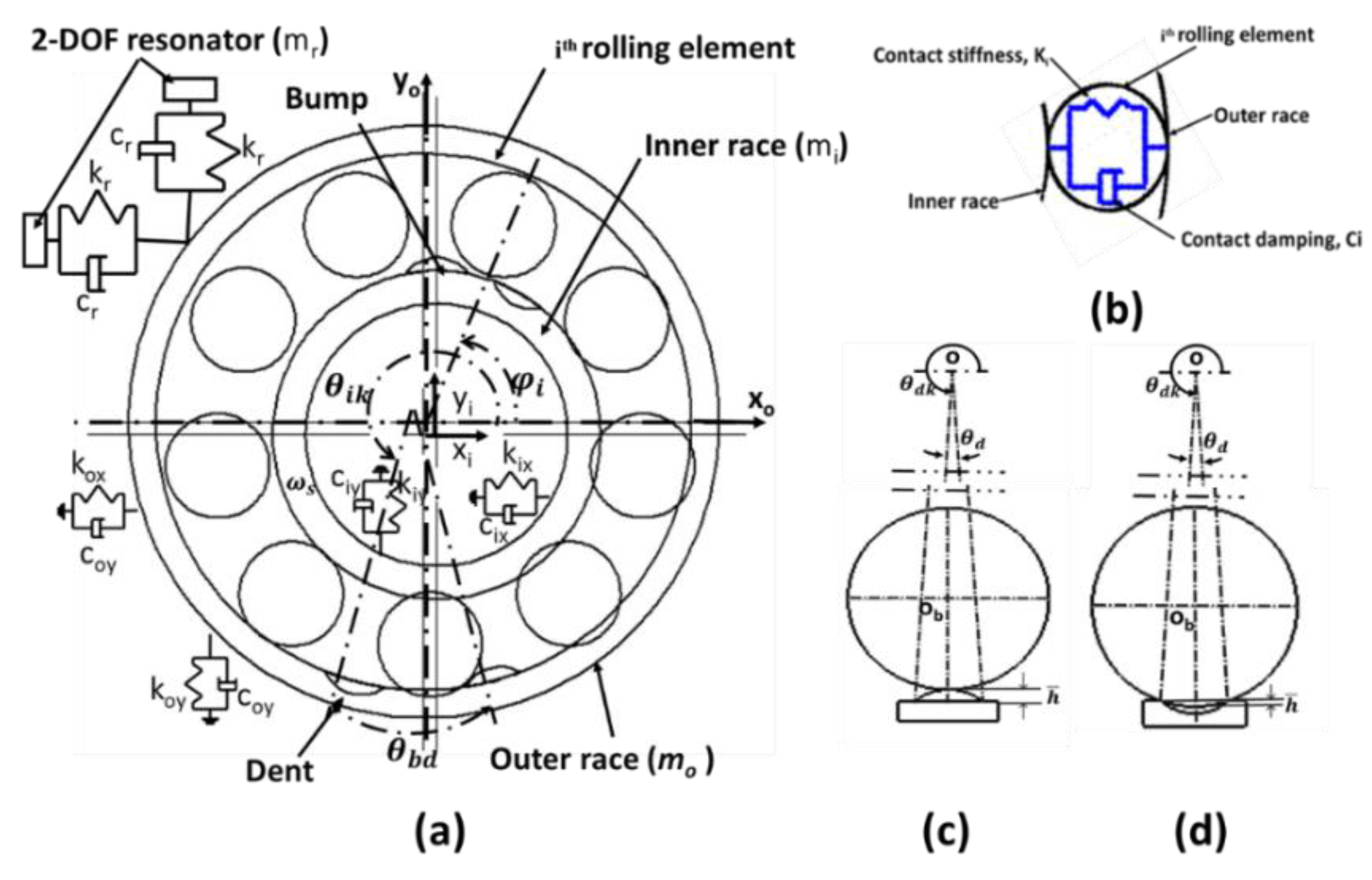
Figure 1. (a) Schematic of loaded ball bearing with simulated ball deformation; (b) simplified model of contact and damping force between ball and raceways; (c,d) schematic of contact relation between ball and bump, and ball and dent.
Machines 10 01062 g001
Figure 2. (a) Cross-section of bump defect, (b) cross-section of dent defect, (c) and top view of bump and dent defect.
Machines 10 01062 g002
Figure 3. Flow chart of solution procedure of dynamic equations of bearing model.
Machines 10 01062 g003
Figure 4. (a) Simulated acceleration signal of healthy bearing and (b) envelope spectrum of simulated acceleration signal.
Machines 10 01062 g004
Figure 5. (a) Simulated acceleration signal of bearing with two dents on its outer race at an angle of 25°, (b) simulated acceleration signal between 0.34 s and 0.36 s, (c) simulated jerk signal in time domain, and (d) envelope spectrum of simulated acceleration signal.
Machines 10 01062 g005
Figure 6. (a) Simulated acceleration signal of bearing with two dents on its inner race at 15°, (b) enlarged simulated acceleration signal between 0.34 s and 0.36 s, (c) simulated jerk signal in time domain, and (d) envelope spectrum of simulated acceleration signal.
Machines 10 01062 g006
Figure 7. (a) Simulated acceleration signal of bearing with double defects (dent and bump) on its outer race at 25°, (b) enlarged simulated acceleration signal between 0.34 s and 0.36 s, (c) simulated jerk signal in time domain, and (d) envelope spectrum of simulated acceleration signal.
Machines 10 01062 g007
Figure 8. (a) Simulated acceleration signal of bearing with double defects (bump and dent) on its inner race at 15° (b) enlarged simulated acceleration signal between 0.34 s and 0.36 s, (c) simulated jerk signal, and (d) envelope spectrum of simulated acceleration signal.
Machines 10 01062 g008
Figure 9. Dynamic response (acceleration and jerk) of a bearing has a bump and dent on its outer race with different angles between them: (a,b) 0.415° (radial distance d), (c,d) 3.139° (radial distance 8 d), and (e,f) 34.8° (radial distance 84 d).
Machines 10 01062 g009
Figure 10. (a) Relationship between time interval t1–2 and angle between defects β, and (b) relationship between peak amplitudes at BPFO and angle between defects β.
Machines 10 01062 g010
Figure 11. Dynamic response (acceleration and jerk) of a bearing has a bump and dent on its outer race with different widths (a) acceleration signals, and (b) jerk signals for 0.34 mm defect diameter; (c) acceleration signal and (d) jerk signal for 2.5 mm.
Machines 10 01062 g011
Figure 12. (a) The relationship between acceleration RMS and defect width, (b) The relationship between maximum peak amplitudes at second BPFO harmonics and defect width.
Machines 10 01062 g012
Figure 13. Dynamic response (acceleration and jerk) of a bearing has multiple bumps and dents on its outer race with 5° angle between every two defects: (a,b) 4 defects, (c,d) 6 defects, and (e,f) 8 defects.
Machines 10 01062 g013
Figure 14. (a) Simulated acceleration signal of bearing with 7 random defects (bump and dent) on its outer race, (b) enlarged simulated acceleration signal between 0.345 s and 0.355 s, (c) simulated jerk signal, and (d) envelope spectrum of simulated acceleration signal.
Machines 10 01062 g014
Figure 15. Test rig of Bearings Data Center at Case Western Reserve University [65].
Machines 10 01062 g015
Figure 16. (a) Acceleration signal of experimental results of single defect on outer race, (b) acceleration signal of experimental results of single defect on inner raceway, (c) envelope spectrum of acceleration signal of experimental results of single defect on outer race, and (d) envelope spectrum of acceleration signal of experimental results of single defect on inner race.
Machines 10 01062 g016
Figure 17. (a) Simulated acceleration signal of single defect on outer race, (b) simulated acceleration signals of single defect on inner race, (c) envelope spectrum of simulation results of single defect on outer race, and (d) envelope spectrum of simulation results of single defect on inner race.
Machines 10 01062 g017
Table 1. Geometrical specifications of 6205-2RS JEM SKF deep-groove bearing [60,61].
ParameterValue
Inner race diameter, Do25 mm
Outer race diameter, Di52 mm
Pitch diameter, Dp39.0398
Ball diameter, db7.94004
Number of balls, z9
Contact angle, α
Radial clearance, γ5.5 µm
Load–deflection factor, K1.5779 × 1010.5 N/m1.5
Publisher’s Note: MDPI stays neutral with regard to jurisdictional claims in published maps and institutional affiliations.