1. Introduction
It is necessary to replace human with manipulator under some hazardous circumstances, such as object carrying, surgery, rescue, non-conventional machining, nuclear power plant monitoring, etc. Hyper-redundant manipulators (HRMs) have multiple degrees of freedom and motion modes, and ability for multi-objective optimization, which can achieve excellent environmental adaptability and extremely high obstacle-avoidance ability to perform tasks in small, complex, and unstructured environments. In actual applications, path planning and the solution of inverse kinematics are necessary to complete the movement and control of the manipulator. Therefore, some methods of solving inverse kinematics have been put forward that can be classified into three categories: geometric methods, numerical methods, and intelligent algorithms.
The process of solving the inverse kinematics of HRMs can be converted into an optimization problem by applying numerical methods, and the problem can be solved iteratively as the objective function is determined. There are some methods commonly used in numerical methods, including the Jacobian pseudo-inverse method [
1], damped least-squares method [
2,
3], and gradient-projection method [
4,
5], which can be used to calculate the joint angle in real time according to the position of end-effector. For numerical methods, there are no restrictions on the configurations and geometric parameters of the HRM, allowing a universal solution framework for all kinds of manipulators to be constructed, and the calculation process is more flexible. However, real-time performance and high precision cannot be achieved simultaneously in numerical methods, and the setting of the initial point also affects the convergence of numerical methods. Due to the existence of numerous iterations, the solving speed of the numerical method is generally much slower than that of the geometric method under the same accuracy requirements, and the existence of cumulative errors will also affect the control accuracy.
With the development of intelligence, more and more intelligent optimization algorithms have been proposed to resolve the inverse kinematics of the HRM, such as neural network algorithms [
6,
7,
8], particle swarm optimization algorithms [
9,
10], differential evolution algorithms [
11,
12], genetic algorithms [
13], simulates anneal arithmetic [
14], firefly swarm algorithms [
15,
16,
17], artificial bee swarm algorithms [
18], and other intelligent algorithms. Although intelligent algorithms can achieve an optimized solution, multiple iterations are carried out, resulting in a longer calculation time with a loss of the capability for real-time solving and a possibility of falling into the local optimal point or non-convergence, while the ability to avoid obstacles is not considered in many intelligent algorithms.
The process of solving inverse kinematics by using numerical methods [
19,
20] and intelligent algorithms is often more complicated; thus, geometric methods have been introduced to simplify the process, reducing the difficulty of solving. As the earliest applied methods for solving the inverse kinematics of HRM, these methods only simplify the concrete structure of HRM, establish constraint equations between the link and the position of the end-effector by geometric relationship, and then solve the angle of the joint by the end-effector position. The process of geometric methods can be generally divided into three steps: (1) Determine the configuration of the HRM, (2) solve the coordinates of each key point, and (3) solve the angle of each joint. The computational speed, efficiency, and accuracy of geometric methods are better than those of numerical methods requiring an iterative solution, and the computational complexity is lower than that of numerical methods and intelligent algorithms, which is convenient for achieving the real-time control of the HRM. Geometric methods possess the advantages of great geometrical intuitiveness and low computation cost, and can be divided into several types: repeated path method [
21,
22,
23], ridge method [
24], segmented geometry method, equally effective method, parameterization method, etc.
Xie [
22] proposed a repeated path method for a rigid snake manipulator, which has high positioning accuracy and a short computation time. The repeated path method can be utilized to solve the inverse kinematics of snake robots, cable drive manipulators, continuous manipulators, and flexible manipulators. However, the inverse solution is unique and certain, and the curvature of the path cannot be too large, which limits the motion space of the manipulator and reduces the flexibility and redundancy of the HRM. Jia [
23] proposed the MDA + RRT algorithm for path planning on the basis of the RRT algorithm, and theoretically analyzed the relationship between four parameters, i.e., the length of the link, the maximum joint angle, the step of the path, and the maximum angle between two adjacent lines in the path, so as to solve the problem of the limitation of the deviation angle of a joint in the HRM.
The traditional ridge line method fits all key points to the ridge line, reducing the redundancy of HRMs. Zhang [
24] designed the expression of the spiral curve based on the ridge method and proposed a shape-fitting algorithm to constrain the macroscopic shape of snake robots and calculate the angle of each joint in the process of motion by using the phase-shifting and angle-solving algorithm. The ridge line method is mostly used for snake robots, quasi-continuous manipulators, or continuous manipulators, especially for HRMs with degrees of freedom greater than 20. The application of the ridge line method to HRM can greatly reduce the difficulty of solving inverse kinematics, but the redundancy of HRM will also be greatly reduced.
The geometric methods mentioned above can hardly meet the constraints of obstacle avoidance and cannot take advantage of the redundancy of HRM. With the help of Robotics Toolbox and ROS, only the end trajectory can be planned while leaving other problems unsolved, and the inverse kinematics can not be solved under a circumstance where there are too many degrees of freedom. Alejandro [
25] proposed a novel variant of differential evolution for variable-length vector optimization named VLV-DE, which worked well for mobile robots, but was not suitable for redundant manipulators. The research for the corresponding path planning and inverse kinematics of the snake manipulator (quasi-continuous manipulator) still focuses on follow-the-leader (also known as path-following planning, tip following, and snake motion) repeated path planning. The end-effector and each joint move along a path planned by these methods in repetition, which limits the redundancy of HRM, and the results of inverse kinematics solutions are undesired.
The traditional method for solving the inverse kinematics of HRM cannot control the motion path of the intermediate joint, or, at most, one or two joints. The solving process is complicated, and obstacle avoidance cannot be taken into account in the solving process. In this paper, a novel path planning and inverse kinematics solution method, “varied dimensional scaling method (VDSM)”, is proposed. The method scales the path of the end-effector under a certain proportion and adjusts the path of the end-effector and each joint according to the specific position of the obstacle, which is in possession of good versatility.
The VDSM introduced in this paper inherits the advantages of the traditional geometric method:
Solvable. Problems can be solved when the inverse kinematics of the HRM is difficult to solve and the solution is not unique;
Real-time. Compared with numerical methods and intelligent algorithms, fast calculation speed and low computational complexity are achieved, which are convenient for the realization of real-time control;
Intuitive. Good geometric intuition is exhibited.
Compared with traditional methods and other methods, the VDSM has the following characteristics:
Obstacle avoidance. This method makes full use of the redundancy performance of HRMs to achieve obstacle avoidance;
Variability of dimension. This method converts 3D paths into 2D paths. After the 2D paths of the end and each joint are planned, these are then converted into 3D paths to solve the inverse motion and acquire the change rule of the angle of each joint;
Constant ratio. According to the length of each link, the scaling relationship can be developed by this method to carry out path planning and solution of inverse kinematics;
Efficiency. This method can change the fewest degrees of freedom to realize the motion of the end-effector on the desired path;
Simplification. This method converts the 3D obstacle avoidance into a 2D obstacle avoidance and simplifies the solving process of inverse kinematics while retaining the redundancy of the manipulator;
Non-iterative. This method requires no iterative solving during the solving process of inverse kinematics, and the inverse kinematics solution can be obtained at one time;
Generality. This method is appropriate for all kinds of obstacle environments.
The layout of this paper is as follows. In
Section 2, the manipulator is modeled and the transformation relationship between the joint angle and link angle is derived.
Section 3 describes the principle of VDSM where no obstacle exists.
Section 4 introduces the principle of VDSM when there are obstacles, including three obstacle environments.
Section 5 presents the transformation relationship between various motion parameters.
Section 6 verifies the effectiveness of the VDSM through simulation under three kinds of obstacle models. In
Section 7, the effectiveness of the VDSM is checked by experiments.
Section 8 presents the conclusion.
2. Modeling
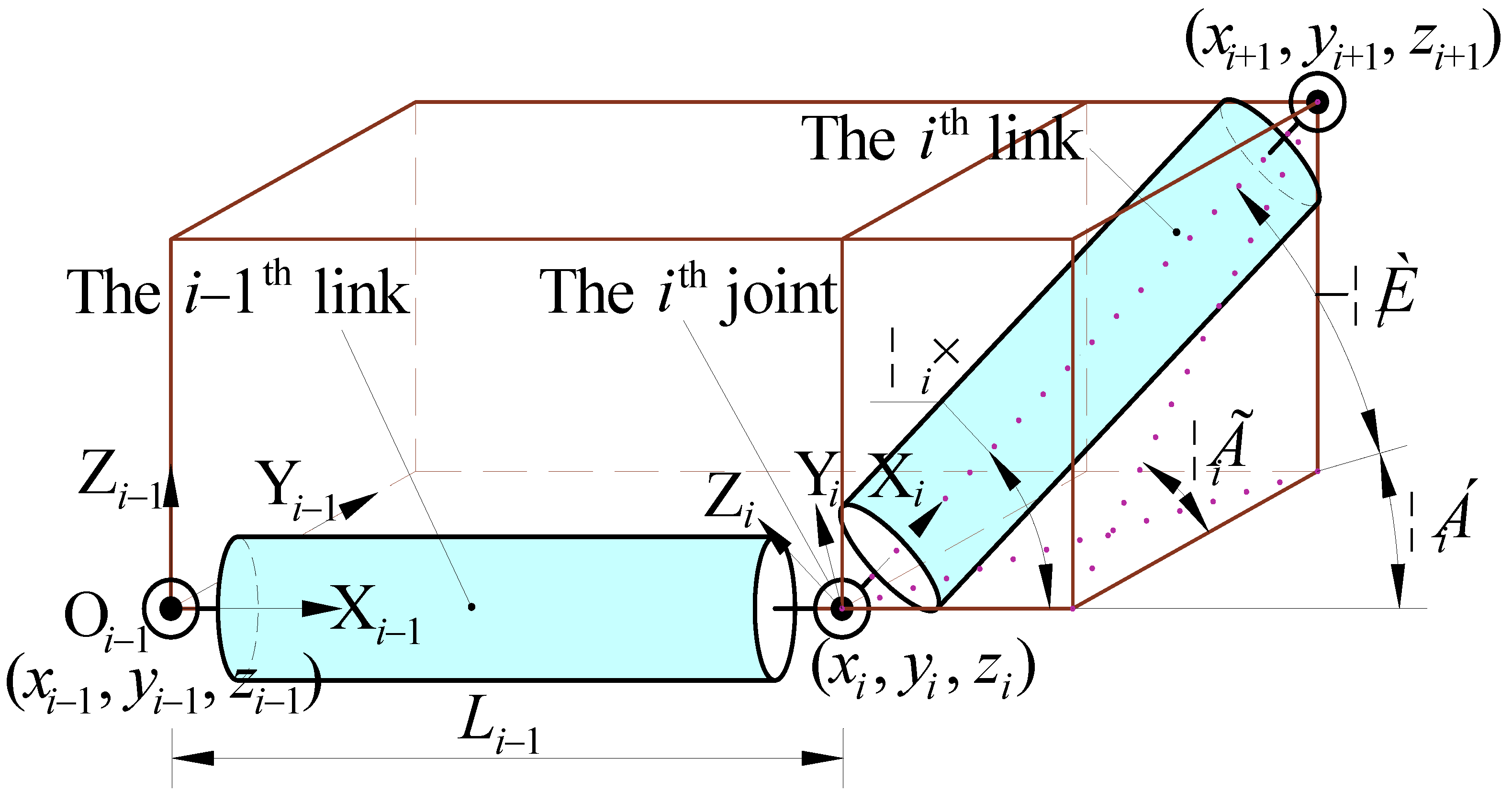
The model of the cable-driven HRM and Denavit–Hartenberg (D-H) coordinate system are shown in
Figure 1. The entirety of the manipulator possesses a translational freedom X
0 in one direction along with the propulsion platform. The manipulator is composed of eight serial links with a total of 16 rotational degrees of freedom, and each link has two degrees of freedom: pitch angle
θi and yaw angle
αi. Each link is driven by three cables, and the position of each cable is driven by each motor. In total, 24 cables are driven by 24 motors, controlling 16 rotational degrees of freedom of the eight links.
In order to analyze and solve the kinematics of the cable-driven HRM, the corresponding D-H coordinate system should be established. However, as a general solution method, the D-H method is not unified in its standards, which are often established with different rules and habits. In the traditional D-H coordinate system, the coordinate system shown in the first line of
Figure 1 is used to establish the D-H coordinate system with 16 degrees of freedom, and the parameters of the D-H coordinate system in 16 lines need to be listed. In order to facilitate the calculation of the forward and inverse kinematics, 16 coordinate systems are simplified into 8 coordinate systems, as shown in the middle row in
Figure 1 in this paper, which are presented in
Table 1. The transformation matrix between the two coordinate systems can be obtained by making the coordinate {O
i−1} translate ai along the X
i−1 axis, rotating
αi of Z
i−1, then rotating
θi to coordinate {O
i}, and finally translating
di along Z
i axis, as shown in Equation (1).
where c stands for cos and s stands for sin, and these abbreviations are adopted hereafter.
and
represent the rotation transformation matrix and the translation transformation matrix of the coordinate system {O
i} relative to {O
i−1}, respectively, and
ai is equal to
Li−1, which is the translation distance of the coordinate system.
In this paper, the links are connected through a universal joint that can rotate in both the pitch and yaw directions. In other words, the
ith universal joint has two degrees of freedom,
θi and
αi, which can be converted into the link angle
ψi (link angle is the angle between the axes of adjacent links) and position angle
γi (position angle is the angle between the projection line of the posterior link on the vertical surface of the preceding link and the horizontal line) to analyze the relationship of the location between adjacent links. The relationship between the joint angle and link angle can be observed in
Figure 2, and the following conversion equation can be obtained.
Through the transformation matrix, the mapping relationship among the length of the driving cable, joint angle, and the position of the end-effector of each link can be analyzed, which is introduced in
Section 5.
Solving each joint angle and an overall translation distance by the position of the end-effector (x9, y9, z9) required three given equations to obtain 17 parameters, corresponding to an infinite number of solutions. To solve the non-uniqueness, reduce the complexity of the inverse kinematics of HRM, and realize the performance of obstacle avoidance, a novel method of path planning and solving inverse kinematics, variable dimensional scaling method (VDSM), is proposed in this paper.
3. Principle of VDSM without Obstacles
3.1. General Framework of VDSM
The VDSM flowchart presented in this article is shown in
Figure 3.
In this paper, by taking the way in which the end-effector moves along the 1500 × 1500 square on the plane X0 = = 3126 as an example, the principle of the VDSM is described specifically with no obstacles and three different obstacles.
Firstly, the principle of VDSM is analyzed when there is no obstacle. As can be observed in the flow chart, the influence of obstacles does not need to be considered in Step 1, Step 2, and Step 3 of the VDSM. The principle of these three steps is described successively as follows.
3.2. Step 1: Determining the Feasibility
The range of parameters of the manipulator is limited, which limits the overall range of motion of the manipulator. The motion range of the HRM in this paper can be regarded as unrestricted in the range of the X
0 axis, and the motion range in the plane Y
0Z
0 is in a circle with the projection of the X
0 axis on the plane as the center
ryz as the radius. In this paper, if
ψi ≤ 42.5°, the maximum distance between the end of the manipulator and the X
0 axis, that is, the motion radius
ryz = 2966 mm, can be obtained by the following equation:
This step is required to determine whether the end-effector can reach the desired position without considering obstacles according to the motion range of the HRM. If positive, proceed to the next step. If negative, terminate the algorithm.
3.3. Step 2: 3D→2D
Because the manipulator as a whole has translational degrees of freedom along the X0 axis, its motion range is not limited. However, there are no overall translational degrees of freedom in the Y0 axis and Z0 axis directions, and the range of motion is limited. By taking advantage of the flexibility of the X0 axis, the 3D problem can be projected along the X0 axis at first, and then transformed into a 2D problem to reduce the complexity of solving the inverse kinematics.
The expected 3D path of the end-effector is projected on the plane Y0Z0 in this step. In other words, the planned 3D path of the end-effector is transformed into a 2D path, which lays a foundation for the path planning of the center point of the intermediate joint.
3.4. Step 3: Scale the Path
In this step, the 2D path of the end-effector is scaled to obtain the 2D reference path of the center point of each intermediate joint.
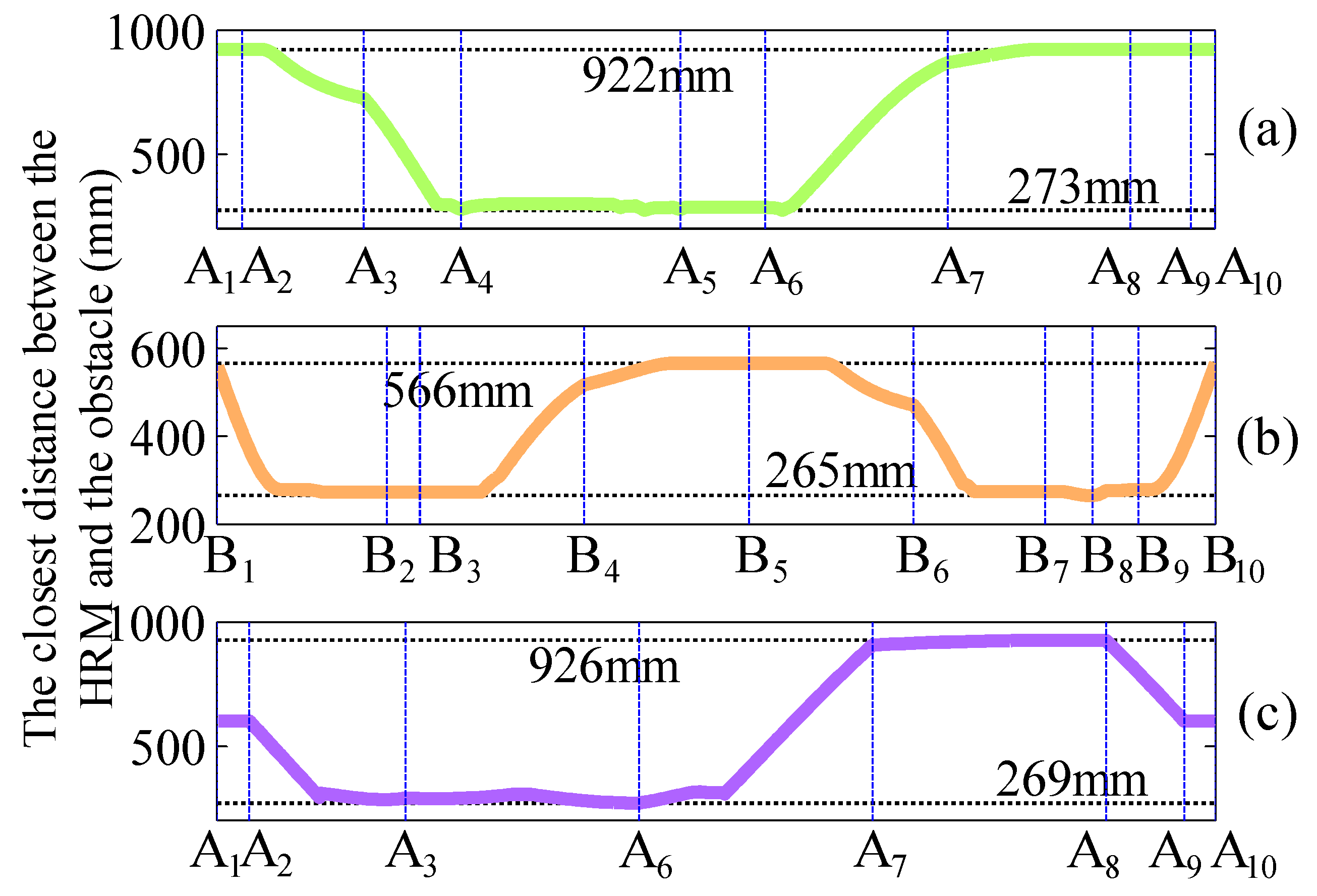
Depending on the length of each link, a definite scaling relationship can be obtained. When not considering obstacles, the 2D path of the end-effector is employed to calculate the 2D path of all center points of the joint projected on the Y0Z0 plane. In this step, only the best 2D motion path of each joint center is obtained without considering obstacles, which provides references for better accommodation under circumstances with obstacles. For example, the 2D practical path of each joint is limited to no more than the 2D reference path in obs2.
3.5. Scaling Relationship
In this section, the scaling relationship among the 2D motion paths of each joint center point is described, and according to the scaling relationship, the 2D motion of each joint center point considering no obstacle is solved; then, the 3D motion paths of all joint center points are planned. The long links are shown in purple, and the three short end links are shown in blue.
The motion path of the end-effector O
9 draws the black square wire frame shown in
Figure 4 on the plane X
0 =
= 3126. The rotation center of the first joint O
1 can only move along the X
0 axis, so the projection of its path along the X
0 axis is a point.
To solve the problem of non-uniqueness and complexity of solving the inverse kinematics, the projection of the path of the rotation center point O
1–O
8 from the first joint to the eighth joint along the X
0 axis and the path of the end-effector are defined as a certain scaling ratio
k1_9−
k8_9, which are related to the length of the link
Li, as shown in Equation (5). It can be seen, in the equation, that the value of
ki_9 is between 0 and 1.
The above equation only analyzes the scaling relationship
ki_9 between the position of the
ith joint center point and the position of the end-effector, and the denominator is the total length of all links. According to this equation, the scaling relationship
ki_j between the position of the
ith joint center point and the position of the
jth joint center point can be deduced:
According to the above relationship of the scaling ratio, the 2D path projected by all joint nodes on the Y
0Z
0 plane can be planned according to the 2D path of the end-effector. According to the length
Li of each link, the 3D path of all joint center points from the end-effector to the first joint center point can be obtained. For example, given the 3D coordinates (
xi+1,
yi+1,
zi+1) of the (
i + 1)th joint center point O
i+1, the specific values of the 3D coordinates (
xi,
yi,
zi) of the
ith joint center point O
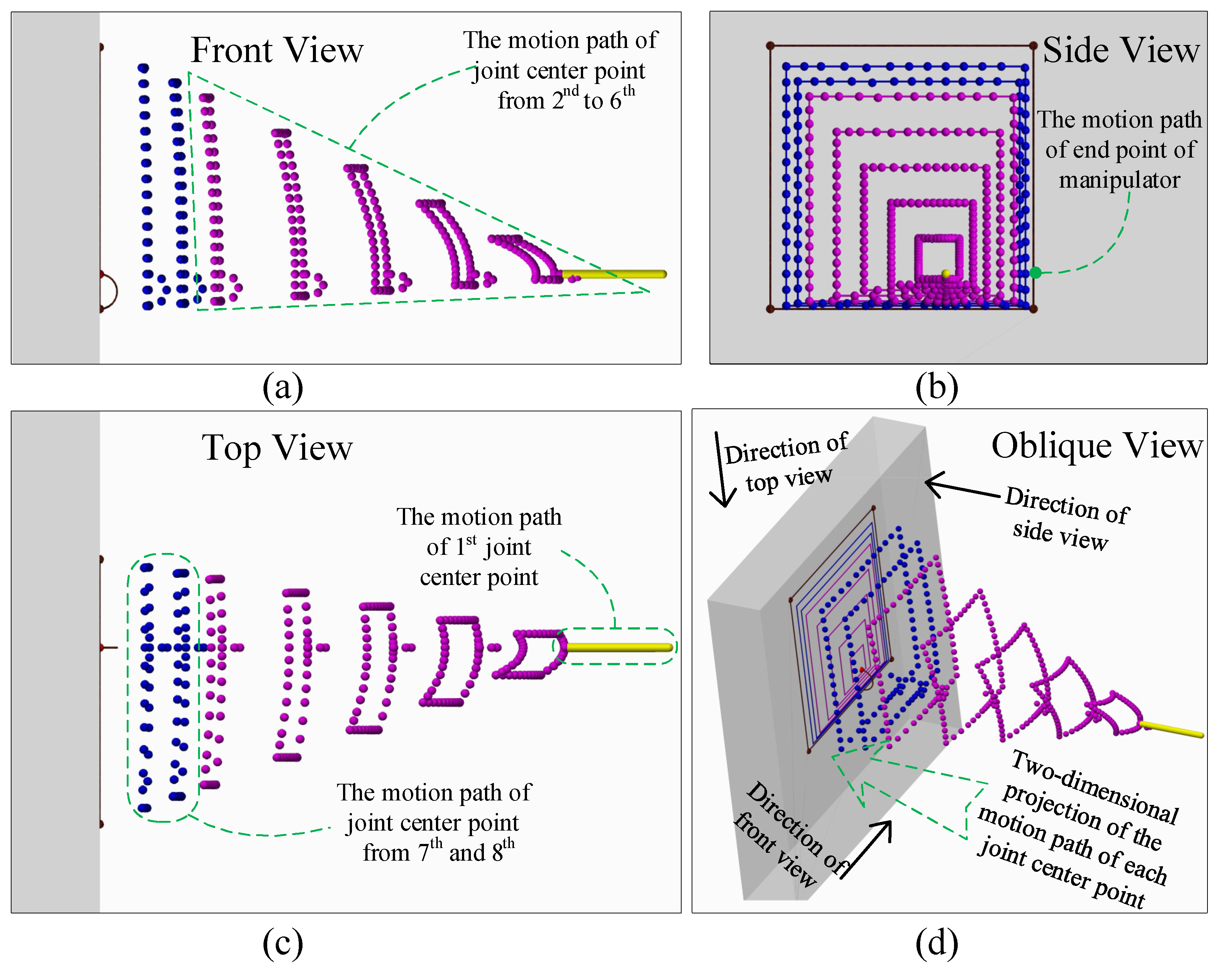
i can be obtained using Equation (7). The 3D and 2D projection diagrams of the paths of all joint center points are shown in
Figure 4.
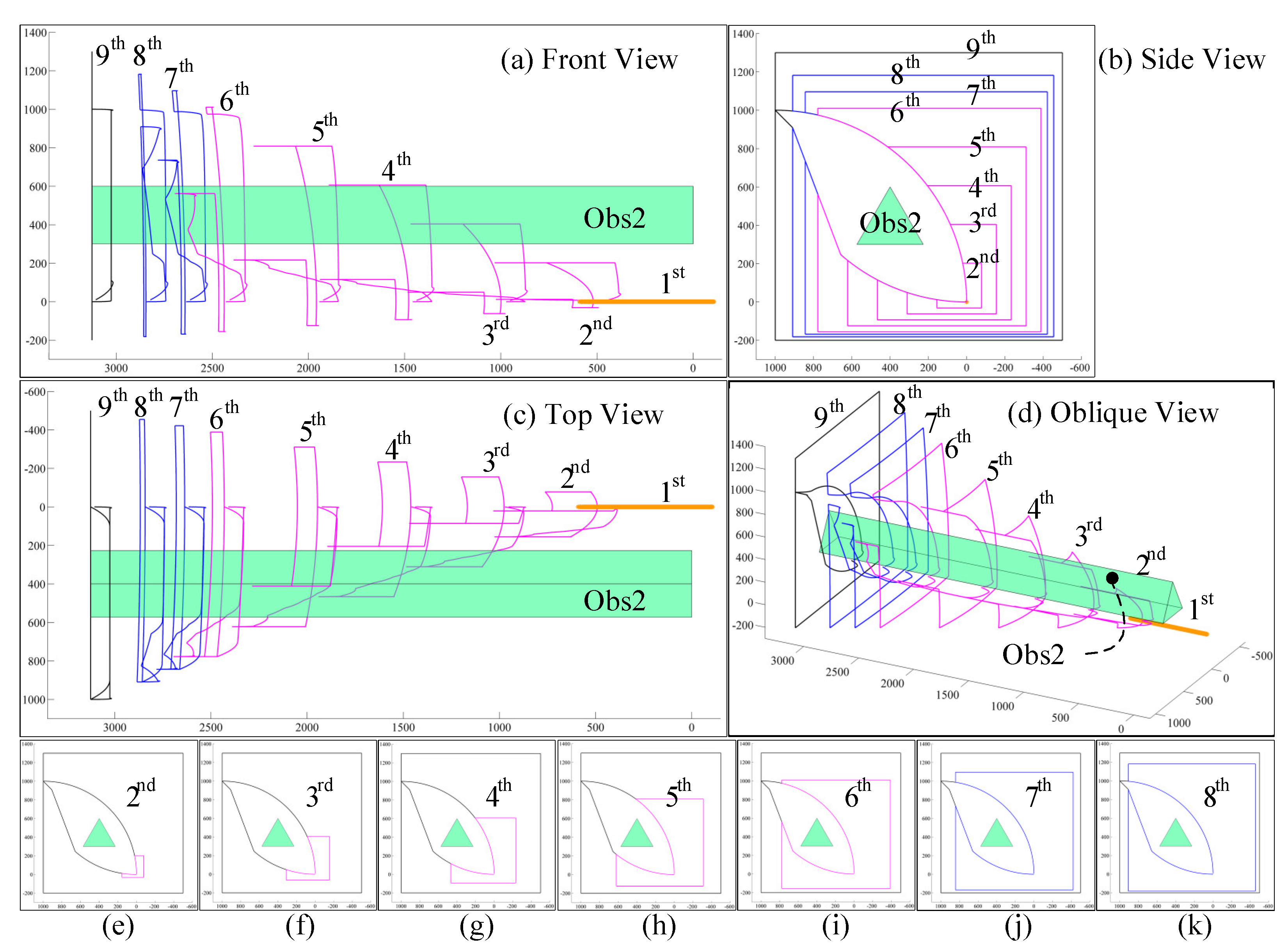
Figure 4 shows the 3D view and oblique view of the motion path of each joint center point, in which each ball represents the discrete point passed by the joint center point. The side view in
Figure 4b and the oblique view in
Figure 4d also include 2D projections of the motion paths of each joint center point. It can be seen from
Figure 4b that the 2D projection paths of all joint nodes are square paths. However, except for the motion path of the end-effector of the manipulator and the center point of the first joint, the 3D paths of the other joint nodes are curves. It can be seen from
Figure 4a,c that the bending radian of the 3D path at the front joint center point is larger, while the bending radian of the 3D path at the back joint center point is flatter.
When there is no obstacle, the inverse kinematics are solved by using the VDSM, and the result is that the eight links are always coplanar. The method adopts as few degrees of freedom as possible to achieve the motion of the end-effector on the expected path, and the previous degrees of freedom are changed in priority: the translational degree of freedom x0, the rotational degree of the first joint θ1 and α1, the rotational degree of the second joint θ2 and α2, and so on.
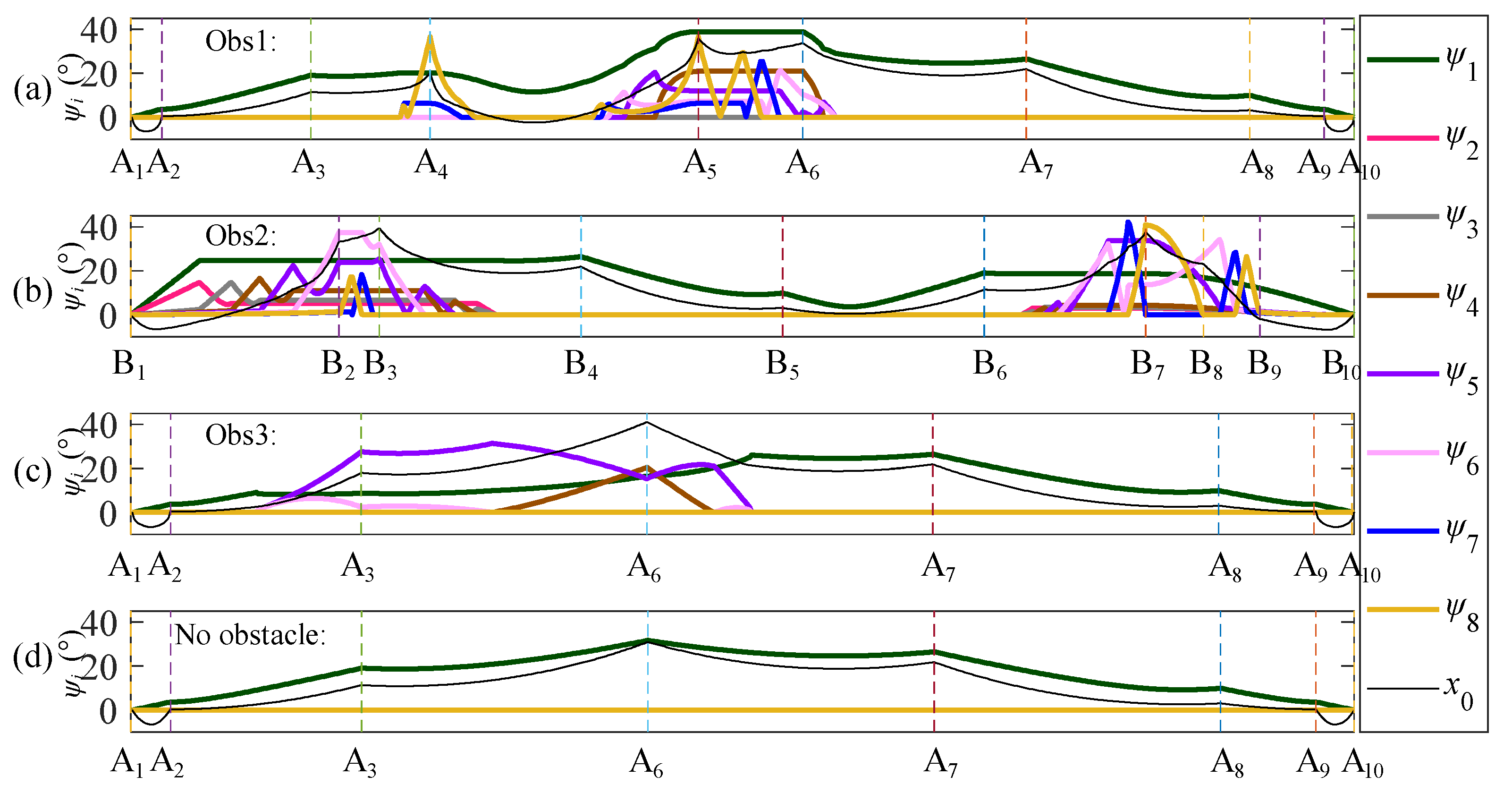
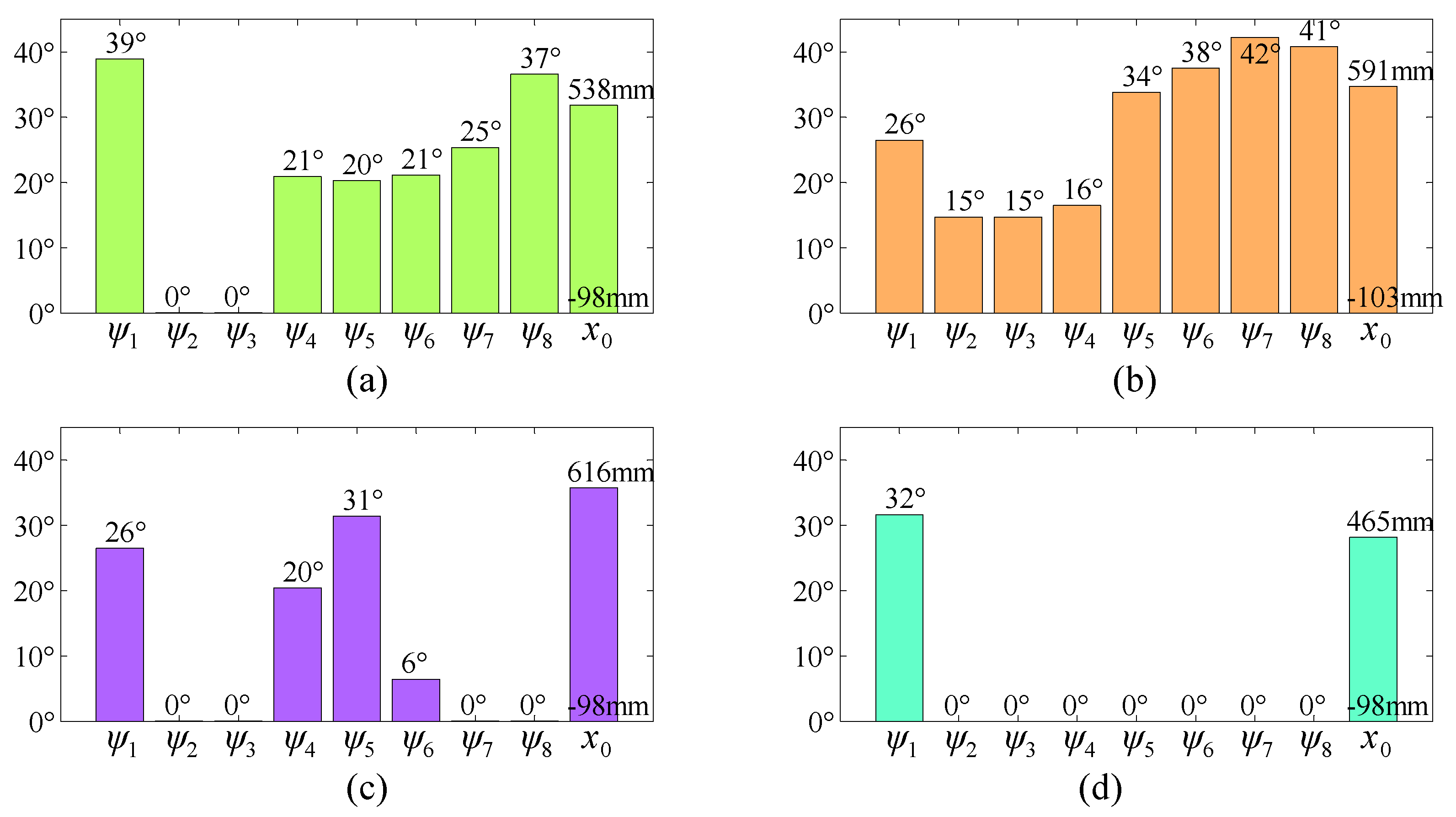
In the example without obstacles, only three degrees of freedom, x0, θ1, and α1, are changed, while the remaining angles remain as zero. In other words, only the overall translational position x0 of the manipulator and the first link angle ψ1 are changed and the other seven link angles ψ2–ψ8 remain as zero. The angle corresponding to each degree of freedom should be zero as much as possible to achieve the desired motion of the end-effector when fewer joint angles are changed.
4. Principle of VDSM with Obstacles
4.1. Obstacle Models
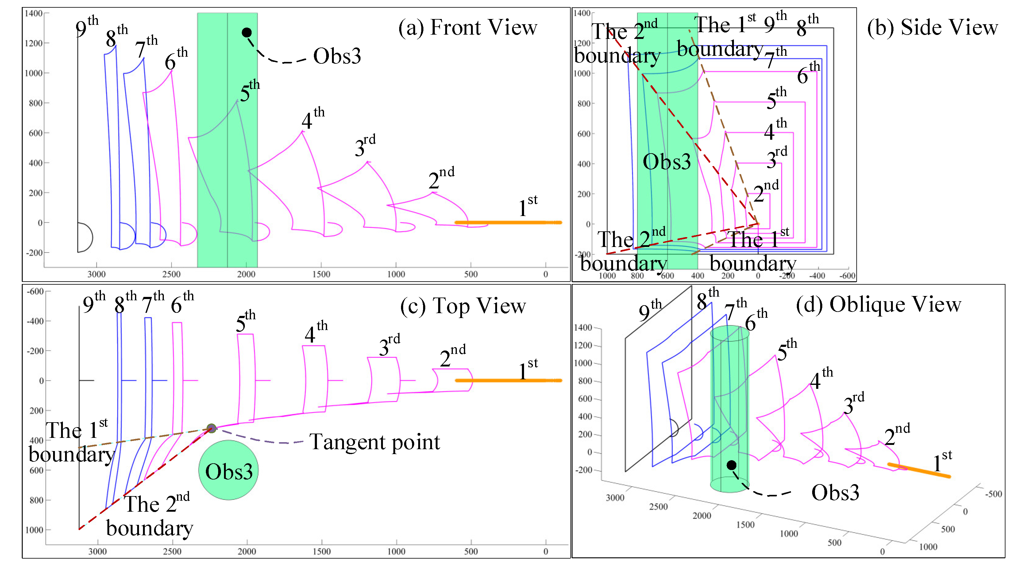
If there are obstacles and the path is still planned according to VDSM, without considering the obstacles in
Section 3, the collision shown in
Figure 5 will occur. When the end-effector moves to point (3126, 1000, 1300), the manipulator will interfere with these three obstacles. Obstacles of the first kind (obs1) are cylindrical, with a radius of 200 located at (
x, 700, 600). The second type of obstacle (obs2) is a triangular prism obstacle with a tangent circle whose radius is 200 located at (
x, 400, 400). Obstacles of the third kind (obs3) are cylindrical with a radius of 200 located at (2126, 600,
z).
For different obstacles, the VDSM without considering obstacles needs to be strengthened according to the specific obstacle model to make each joint center point of the HRM move along the final planned path while retaining the advantages of the VDSM without obstacles.
In Step 4, Step 5, and Step 6 of the VDSM, the influence of obstacles should be considered. The principle of these three steps is described as follows:
4.2. Step 4: Adjust Motion Path of End-Effector
4.2.1. Two Kinds of Problems
When the expected path of the end-effector is known, the following problems need to be analyzed:
- (1)
Whether the initial position of the end-effector is located on the desired motion path must be considered. If not, the corresponding path should be planned so that the end-effector moves from the initial position to the desired path without encountering obstacles and the preliminary motion position of the end-effector on the desired path should be determined;
- (2)
Whether the end-effector will encounter obstacles as it moves along the planned path needs to be defined. If the end-effector encounters obstacles, the path of the end-effector should be adjusted.
This step is divided into several different methods according to the position, shape, size, and initial position of the obstacle to expand the expected path of the end-effector to the actual motion path.
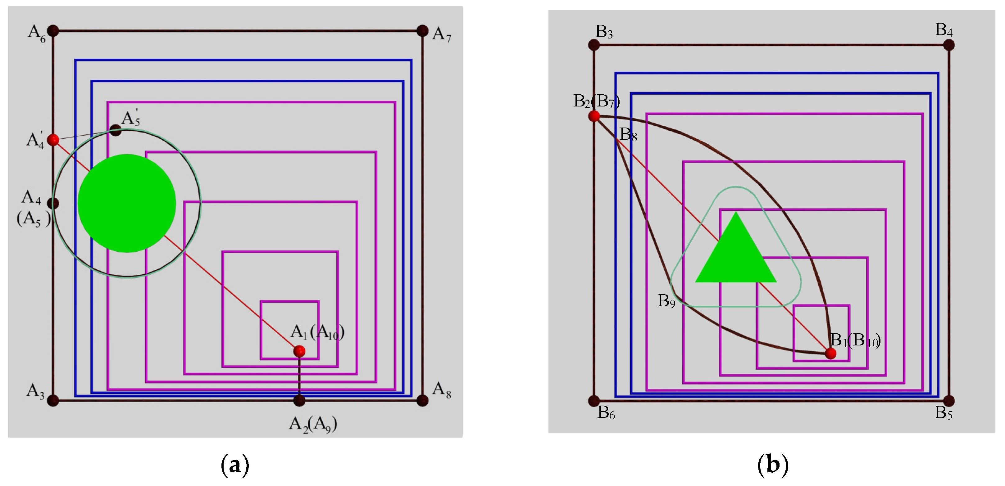
The parameters of three kinds of obstacles were established in the obstacle model. In this paper, the initial state of the HRM was horizontal, and the end-effector of the manipulator was located at point (3126, 0, 0). After projection, it was divided into the points shown in
Figure 6 as A
1 and B
1. The expected path of the end-effector is to draw a 1500 × 1500 square on the plane X
0 = 3126, as shown in the black square at the outermost end of the image. The four vertices of the square in
Figure 6a are A
3, A
6, A
7, and A
8. The obstacles are indicated by green entities. Because of the diameter of the manipulator and the influence of various errors, the safety distance between each joint center of the HRM and the obstacles should be set. The green area around the obstacles in
Figure 6 (projected as the green curve) is the corresponding safe range, and the path is planned as far from the surface as possible. The red points in
Figure 6 are the starting points or equidistant points in the end path of the manipulator, and the red line segments in the figure are the auxiliary lines for finding equidistant points.
4.2.2. Solution to the First Problem
For the first kind of problem, the path can be planned based on various optimizing indexes or projects. In this paper, the initial position of the end-effector does not fall within the expected path, so it is necessary to design a corresponding plan to make the end-effector move from the initial position to the expected path. The three schemes: “Shortest distance”, “To the equidistant point”, and “To the nearest equidistant point” are described in detail hereinafter.
The “Shortest distance” scheme is to identify a point closest to the end-effector of the manipulator on the expected path. The path is then planned from the initial position to the nearest point without touching obstacles. The movement from point A
1 to point A
2 in
Figure 6a is an example.
The “to the equidistant point” scheme aims to find the only equidistant point on the expected path, and then the path is planned from the initial position to the nearest point without encountering obstacles. In obs1 and obs2, the preliminary position A
1 or B
1 is connected to O
obs1 or O
obs2 as the centroid projection point of the obstacle, and the connecting line is extended. The point where the extension line intersects the desired path is the equidistant point. The equidistant point refers to the point on the projection plane perpendicular to the centerline of the obstacle where the distances for reaching the point in two directions equally. For example, both points
in
Figure 6a and B
2 (B
7) in
Figure 6b are equidistant points. The path can be planned from the initial position along the border of the obstacles to the equidistant path when the equidistant points are found in obs2, and paths of other forms can also be planned. In this paper, the complexity of the path is simplified on the premise of guaranteeing that no obstacle is encountered. In this way, the movement in the arc paths above the obstacles from point B
1 to point B
2 is planned, similar to the paths below the obstacles from point B
7 to point B
8. However, there are sometimes multiple obstacles and multiple equidistant points; the “nearest equidistant point” scheme is then needed.
The scheme of “to the nearest isometric point” aims to find the nearest isometric point in several isometric points and then plan the path from the initial position to the nearest point without encountering obstacles.
4.2.3. Solution to the Second Problem
For the second kind of problem, if there is no obstacle encountered in any place by the manipulator during the whole movement process, the path of the center point of each joint can be planned according to the basic VDSM without considering obstacles. Then, the inverse kinematics of the HRM can be solved and the variation law of each degree of freedom can also be obtained. If an obstacle is encountered, the 2D path of the end-effector will be readjusted based on the principle of the VDSM to prepare for adjusting the 2D path of each joint in the next step. Based on the above process, obstacle avoidance can be achieved and the end-effector can complete the task of moving along the desired path.
The obstacles are taken as examples to explain how to adjust the motion path of the end-effector. To avoid encountering obs1, the end-effector can be moved along the following 2D points: A
1–A
2–A
3–A
4–
–A
5–
–
–A
6–A
7–A
8–A
9–A
10, where the arc from point A
5 to point
is the circular arc in the counterclockwise direction in
Figure 6a. Although the equidistant point
is used in the planned path, the path is relatively complex and requires some additional calculations (such as calculating the position of points, etc.). In order to simplify the complexity of the motion path of the end-effector, the 2D motion path of the end-effector is changed to A
1–A
2–A
3–A
4–A
5–A
6–A
7–A
8–A
9–A
10, and the path from point A
4 to point A
5 is a counterclockwise circle around the obstacle in
Figure 6a. In the next step, it will be presented in detail whether the HRM can move to point A
4 (point A
5) bypassing the obstacle. In obs2, the 2D motion path of the end-effector can be planned as B
1–B
2–B
3–B
4–B
5–B
6–B
7–B
8–B
9–B
10, where point B
1 to point B
2 and point B
9 to point B
10 are two arcs in
Figure 6b. The motion path of section B
7–B
8–B
9 is planned to reduce the deflection range of the link angle. In obs3, the 2D motion path of its end-effector is the same as that of the end-effector without obstacles, and the 2D motion path can be expressed as A
1–A
2–A
3–A
6–A
7–A
8–A
9–A
10 in
Figure 6a.
In the process of the end-effector moving from the initial position to the desired path (for example, from point A1 to point A2), and in the process of moving away from the desired path to avoid obstacles (for instance, from point A4 to point A5). The x-coordinate of the end effector (x9) can be appropriately reduced based on planning the two coordinates of y9 and z9 to prevent the end-effector from scratching the plane X0 = 3126.
In this step, the motion path of the end-effector is adjusted according to the obstacles. In the next step, the movement path of each joint center point is adjusted to achieve the purpose of bypassing the obstacle.
4.3. Step 5: Adjust Path of Each Joint
The motion path of the end-effector can be adjusted through Step 4. The HRM may encounter obstacles if the path of each joint is not adjusted.
Assume that the 2D projection positions of the end-effector O
9 and the center points O
8–O
1 of each joint are P
9, P
8 …… P
1. If the location of the end-effector O
9 (
x9,
y9,
z9) is known, according to the proportional relationship and the position of the obstacle, point P
8 can be obtained, then point P
7 can be obtained, and so on until the position of point P
1 can be obtained.
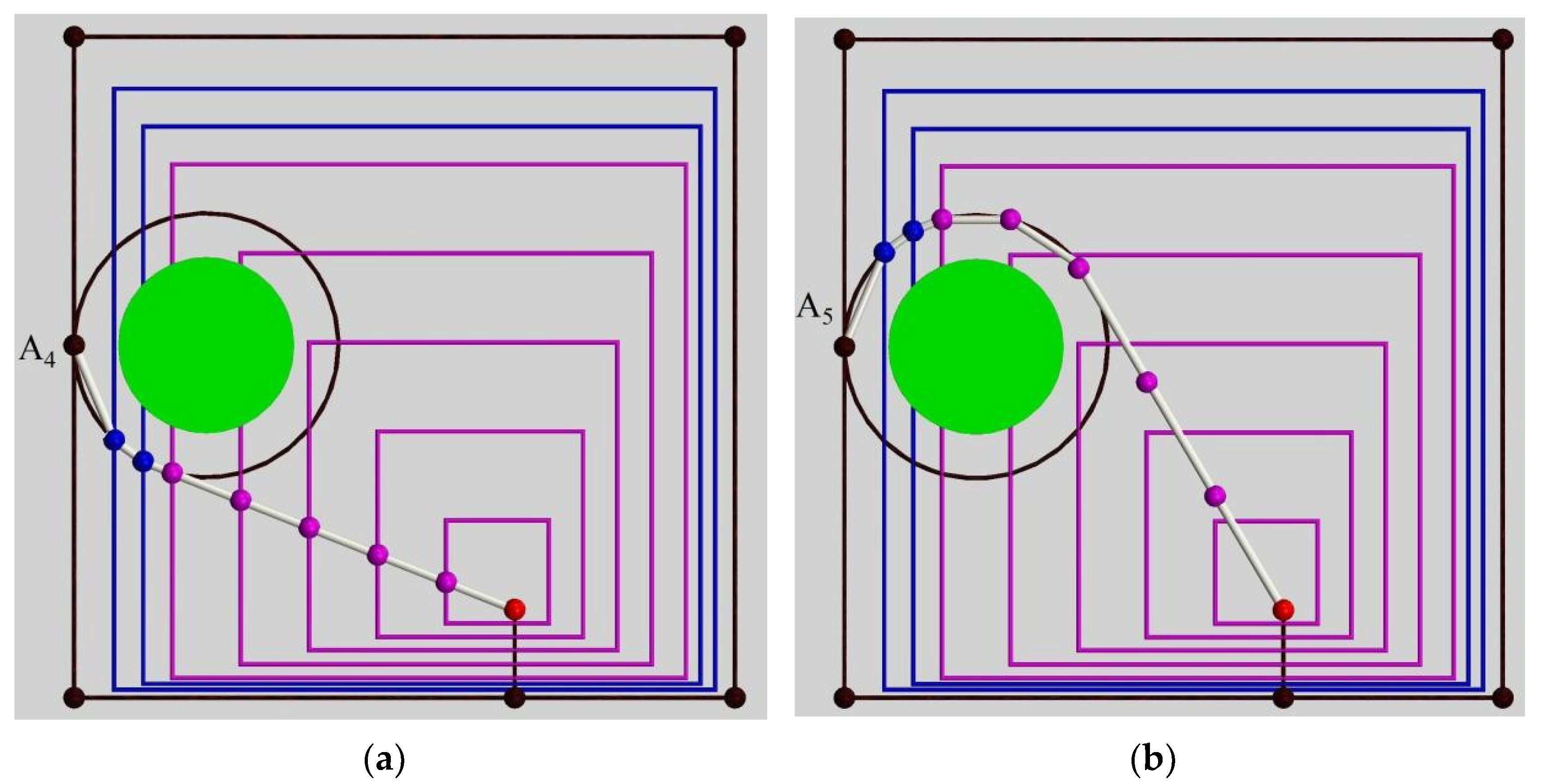
Figure 7 shows the 2D projection diagram of the manipulator when the end-effector is located at A
4 and A
5, respectively. In this method, the 2D projection positions of the center points of each joint are first calculated in the 2D projection plane, and then the 3D position of each point is calculated according to the length of each link. Next, how to solve the 2D projection positions of each joint center point successively for different types of obstacles is described. Because the manipulator in this paper has a translational degree of freedom in the direction of the X
0 axis, the 2D projection for point O
1 is constant as point P
1.
As an example, the end of the effector at point P
9 in
Figure 8 is used to describe how to obtain the position at points P
8–P
2 successively, which corresponds to the situation where the location of the end-effector is affected by the obstacles. Point
can be obtained by connecting point P
1 to point P
9 and adopting the proportional relation as the following equation:
It can be seen from
Figure 8a that point
is not within the safe range, so it is an infeasible point. A horizontal line and a vertical line are drawn to cross the point, and the expected path intersects at four points. According to these four points, the point nearest to the position of the former point on P
8 is selected as the current final P
8 point.
In addition to drawing auxiliary lines, such as a “positive cross” to find the intersection, an “oblique cross” or a circle of radius through point P1 can be employed to find the intersection point. However, when adopting the latter two methods, the link angle will be larger. Therefore, a horizontal line and a perpendicular line are selected to adjust the position of the center point of the joint in this paper.
After the projection P
8 of the eighth joint is obtained, points P
1 and P
8 are connected. Then, point
can be obtained by using the proportion relation as the following equation:
It can be seen from
Figure 8b that the middle point
is not within the safe range, so it is an infeasible point. A horizontal line and a vertical line are drawn to cross the point, which intersect with the expected path at four points. According to these four points, the point closest to the position of the anterior point on P
7 is selected as the final point P
7.
Points P
6, P
5, and P
4 can be calculated by analogy. After obtaining point P
4, point
can be obtained by connecting point P
1 to point P
4 and utilizing the proportional relation as the following equation:
As can be seen from
Figure 8f, point
is within the safety range and can be regarded as the final P
3 point.
As shown in
Figure 8, the successful solution of the 2D projection positions of the center points of each joint is described when the end-effector is known to be at a specific discrete point. In
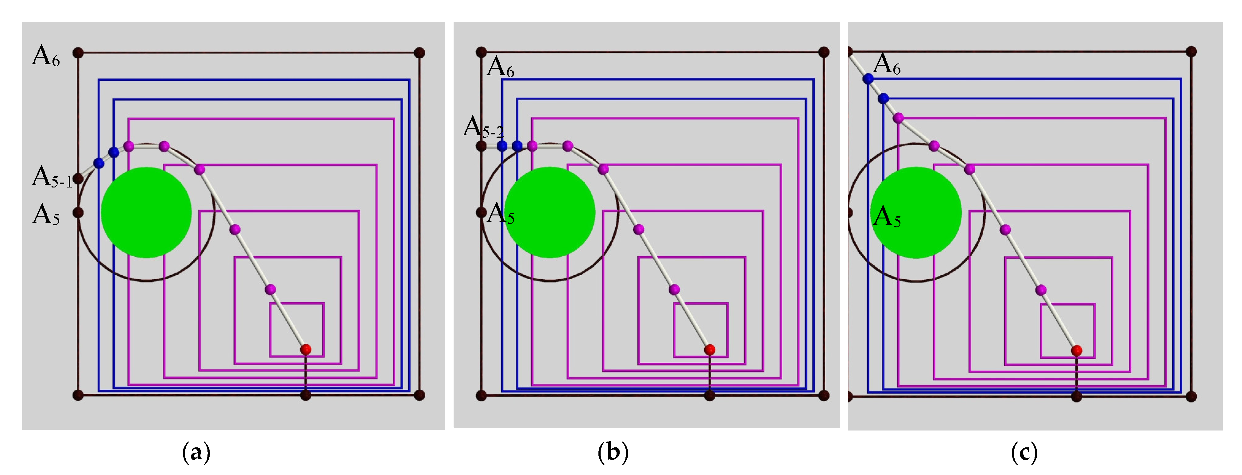
Figure 9, by taking the end-effector moving from point A
5 to point A
6 as an example, it can be demonstrated how the VDSM can be used to solve the 2D projection positions of the center points of each joint during the movement process.
When the end-effector moves from point A5 to point A5-1, only the 2D projection position of the end-effector changes, while the positions of the center points of the other eight joints remain unchanged. When the end-effector moves from point A5-1 to A5-2, in addition to the effector at the end of the 2D projection position changing, the eighth joint center of the projection position also changes, and the seventh joint center of the projection position also changes after a while. However, the projection positions of the six joint centers in the front remain unchanged. In the process of the end-effector moving from point A5-2 to point A6, the 2D projection position will always move along a vertical line. The projection positions of the center points of other joints are also on a corresponding vertical line all the time. By analyzing the above process, it can be concluded that the manipulator always conforms to the principle of the VDSM.
4.4. Step 6: 2D→3D
In the previous step, the final 2D projection position of each joint center can be solved by analyzing the position and proportion coefficient of the end-effector and whether the joint center point is in the safe range. In this step, the 3D position and 3D path of each joint center can be successively solved by Equation (7), and the 2D path between the end-effector and each joint center can then be converted into a 3D path.
In this step, the 3D motion paths of the end-effector and the center points of each joint can be planned. Next, on the premise that the 3D path is known, the inverse kinematics are solved through Step 7 to build a mapping model among the coordinate points, angle of each joint, and length of each driving cable.
5. Conversion of Motion Parameters
After the 3D position and the 3D path of each node are obtained, the variation law of the pitch angle θi and yaw angle αi of each joint can be obtained from the initial joint successively through the position parameters. Finally, the angle is converted to the length of the driving cable. The following is a detailed explanation of the mapping relationship between the parameters.
5.1. Mapping Relationship between Angles and Coordinates
The coordinates (
xi,
yi,
zi) (
i = 1, 2, …, 9) of all key points O
i can be obtained by following the previous steps. First,
α1 and
θ1 can be obtained from (
x1,
y1,
z1) and (
x2,
y2,
z2), and the equation is as follows:
The value of
α1 and
θ1 can be solved in the natural coordinate system. However,
α2 and
θ2 are the deflection angle of the second link with respect to the first link, instead of the angle of the second link in the natural coordinate system. Therefore, when solving the deflection angle of the
ith link with respect to the (
i − 1)th link, the coordinate points need to be converted from the natural coordinate system to the coordinate system {O
i−1} of the (
i − 1)th link.
where (
xi+1_i−1,
yi+1_i−1,
zi+1_i−1) is the coordinate of the
ith link end point O
i+1 in the coordinate system {O
i−1}. The coordinate in the coordinate system {O
i−2} can be converted to the coordinate system {O
i−1} through
. The matrix
is the inverse matrix of the matrix
, which contains three parameters,
αi−1,
θi−1, and
Li−1.
The deflection angles
αi and
θi of the
ith link relative to the (
i − 1)th link can be obtained by (
xi+1_i−1,
yi+1_i−1,
zi+1_i−1), and the specific equations are as follows:
The 16 deflection angles can be successively solved according to the above equation and can be converted into eight link angles with the introduction of
Section 2.
5.2. Mapping Relationship between Cable Length and Angles
The deflection angle of each joint can be obtained by the coordinates of each joint position; then, the length of each driving cable at the joint can be obtained by the deflection angle of each joint and, next, the total length of each driving cable can be obtained by the sum.
In this paper, each joint of the manipulator is driven by three parallel driving cables. One end of the driving cable is fixed to the end face of the joint, and the other end is fixed to the driving mechanism of the base. Under the limitation of the universal joint, the link can be pulled by the driving cable to rotate the joint. There are 27-3 i (i = 1,2,…,7,8) driving cables passing through the ith link, but only 3 driving cables are used to drive this link, with the rest of the driving cables passing through this link to drive the following link.
Taking the first joint as an example, the relationship between the lengths of the 24 driving cables at the joint,
α1,
θ1, and the position angle
φ of the driving cable is analyzed.
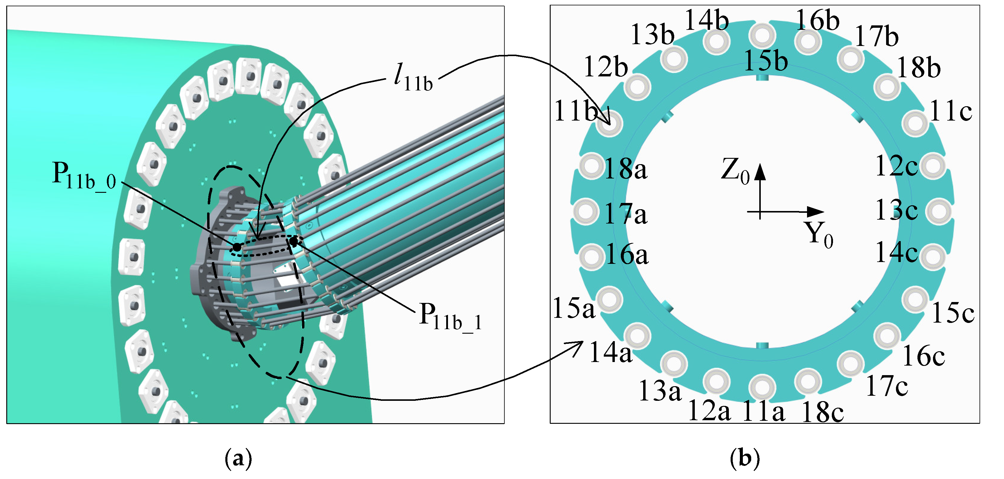
Figure 10 shows a schematic diagram of the placement of 24 cable holes, and the included angle between 2 adjacent cable holes is 15. Holes
ija,
ijb, and
ijc represent the three holes on the
ith (
i = 1, 2,…, 8) link and are distributed into 120 uniformly. The three driving cables pass through holes
ija,
ijb, and
ijc to drive the
jth (
j = 1, 2,…, 8 and j ≥
i) link. When the position angle of each hole in
Figure 10 is
φ, the angle between the line, which is drawn by connecting the center of each hole and the center of the section, and the Z
i axis is the position angle
φ of the point, so
φ15b = 0,
φ16b = 15 …
φ11a = 180 …, and
φ14b = 345 = −15.
The position of each point can be obtained by the position angle φ of each driving cable, which can be converted into the same coordinate system through coordinate transformation. Then, the distance between the two points can be obtained, and the mapping relationship between the length of the driving cable (lija, lijb, and lijc) and the joint angles (αi and θi) of one joint can be obtained.
By solving the driving cable through hole 11b as an example, the calculation of
l11b is described. The position of point P
11b_0 in the coordinate system {O
0} is (
x11b_0,
y11b_0,
z11b_0), and according to the position angle
φ11b of hole 11b, the following can be calculated:
where
d is the distance between the center point of the joint and the end face of the link and
r is the distance between the center of the hole through which the driving cable passes and the center of the link.
The position of point P
11b_1 in the coordinate system {O
1} is (
x11b_1,
y11b_1,
z11b_1), and the position angle
φ11b of hole 11b can be obtained as follows:
The position coordinates of point P
11b_1 can be converted to the coordinate system {O
0} through the transformation matrix
, and then the difference between point P
11b_0 and point P
11b_1 in three directions can be obtained by the following equation:
Then, the distance between point P
11b_0 and point P
11b_1 can be obtained:
After derivation,
where
θ =
θ1,
α =
α1,
φ =
φ11b.
Equation (20) is a general equation. The real-time length of the driving cable at the joint can be obtained by inputting two deflection angles,
θ and
α, and the position angle
φ of the driving cable. After solving the length of the driving cable at each joint and adopting the following equation to sum the length of each segment of the driving cable, the total length of each driving cable can be obtained:
where
lja,
ljb, and
ljc are respectively the total length of the three driving cables driving the
jth link.
In short, the positions of the center points of joints can be deduced by the VDSM, then the angles of joints can be solved by the positions, and, finally, the lengths of 24 driving cables can be calculated by the angles.
7. Experiments
The path drawn by the VSDM is a non-repeated path, and the dynamic picture of the manipulator moving along the path can be generated by the simulation software, verifying the VSDM. In this section, for the third obstacle, VSDM is used to plan the path, and the feasibility of the algorithm is verified by experiments. In order to improve the accuracy and robustness of the manipulator operation, a basic PID closed-loop control system is designed, and the corresponding experiments are carried out to obtain the motion diagram of the HRM, as shown in
Figure 19. It can be seen from the figure that the HRM can not only avoid obstacles, but also achieve the purpose of moving the end along the square path.
The actual change curve of the joint angle, as shown in
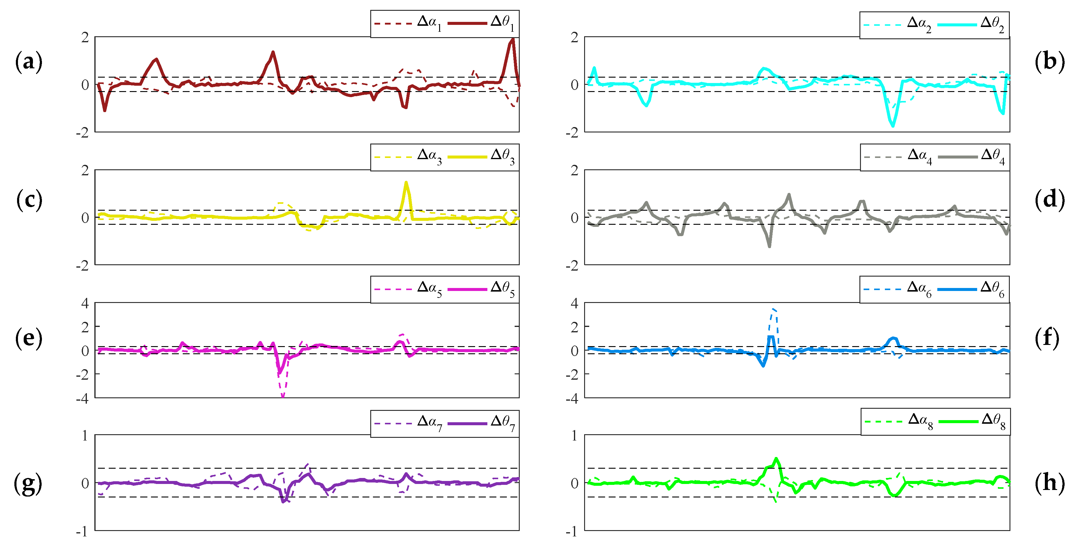
Figure 20, can be obtained through experimentation, which is very close to the theoretical change curve of the joint angle obtained through simulation. According to the difference between the theoretical value and the actual value, the error curve of the joint angle shown in
Figure 21 can be obtained.
Figure 20 and
Figure 21 contain the change curves of the actual values and error of 16 joint angles, and the error curve of each joint angle includes two dashed lines of ±0.3° to show the main range of the error change.
From
Figure 20 and
Figure 21, it can be seen that the error is small, the joint angle is always within 35°, and the link angle is always within the specified range, which verifies the VDSM corresponding to this experiment. At the same time, it can be verified that, by adopting this method, the end point can move along the desired path while avoiding obstacles with as few changes in the degrees of freedom as possible. In this experiment, only 6 rotational degrees of freedom are changed, and the expected value of the other 10 rotational degrees of freedom is always 0°. The only drawback is that there is external interference in the experiment, which results in a large joint angle error in some places. For example, the errors of
α5 and
α6 are about 4° under the effect of interference, but the error quickly changes to less than 0.3° according to the regulation function of the closed-loop system. In conclusion, the actual value of the angle is always within the specified range, and diverse tasks are achieved, which verifies the effectiveness of the VDSM.
Through simulation and experimental verification, it can be concluded that the VDSM has the following main advantages. The method can change the number of link angles as little as possible in the process of achieving the movement of the end-effector along the desired path. The method makes full use of the redundant properties of HRMs and can achieve obstacle avoidance. The method is suitable for all kinds of obstacles.

