1. Introduction
In water conservancy engineering facilities, sluice gates are widely used in rural and coastal river channels as the main water retaining and discharge structures. As the main load-bearing component of the hoisting sluice, the wire rope plays a vital role in the safe operation of the sluice. Due to the long-term exposure of the sluice wire rope to the outdoors, it is affected by irregular bearing, wind, rain, and sun, which will lead to various problems, such as grease hardening, local corrosion, wear, and breakage. Therefore, regular maintenance is essential for the proper operation of the wire rope. Currently, most of the daily maintenance of the sluice wire rope is done manually, leading to problems, such as high labor cost and intensity, low work efficiency, and high-risk factor. With the application of the scientific and technological developments in the field of robotics to the daily maintenance process of the wire rope, the above-mentioned problems can be easily solved. Therefore, the research and development of a wire rope climbing and maintenance robot in the water conservancy industry are anticipated to significantly improve work efficiency in this field, successfully addressing the labor issue in enterprises.
As an important branch of the mobile robot family, climbing robots have received widespread attention from the scientific community in the past two decades. As a result, a wide variety of prototype systems have been developed for specific applications, such as steel bridge climbing robots [
1,
2,
3,
4], cable-climbing robots [
5,
6,
7,
8], pole-climbing robots [
9,
10,
11,
12,
13], tree-climbing robots [
14,
15,
16,
17], pipe-climbing robots [
18,
19], wall-climbing robots [
20,
21,
22,
23,
24], among others.
In terms of rope-climbing robots, Koo et al. [
25] developed a climbing robot based on the piston mechanism for a robotic competition in Malaysia. The robot consisted of a base frame and two clampers. The two clampers were used to grip the rope, and the base frame based on the piston mechanism was utilized to realize the climbing motion. The advantages of the proposed robot are low energy consumption, low cost, and ease to control and build. However, the robot is unable to climb vertically fixed ropes. When the robot is in action, it will occasionally cause vibration along the rope.
Cho et al. [
26,
27,
28] designed three climbing and detection robots for hanger cables of suspension bridges, named WRC
2IN-I, WRC
2IN-I+, and WRC
2IN-II. WRC
2IN-I was composed of a wheel drive mechanism, an attachment mechanism, and a safe landing mechanism. It could climb at 50 mm/s under the condition of a 15 kg load. However, when the wheeled cable-climbing robot moved on the uneven cable surface, it would produce periodic vibration, which would affect the detection quality. Therefore, the project team improved the first-generation cable climbing robot by changing the wheeled structure into a tracked structure, which greatly reduced the vibration. In order to further simplify the installation and disassembly process of the first-generation robot and improve work efficiency, the project team developed the second-generation cable climbing robot named WRC
2IN-II. The robot was composed of two separable attachment modules, two driving modules, and two obstacle-surmounting sub-modules. After improvement, the robot could carry a load of 24 kg, while the installation and disassembly time only took about 5 min. Although these robots are all able to climb vertically fixed wire ropes, their dimensions are large and the applicable cable diameters are 50–90 mm.
Sun, G. [
29] designed a wire rope climbing robot for the detection needs of lamps on the top of airport lighting streetlights. The robot was composed of a compression mechanism, a suspension mechanism, and a tracked type moving mechanism. The climbing robot could maneuver on a wire cable with a cross-sectional diameter varying from 10 to 14 cm with a stable and secure speed of 1 m/s. It could also lift up to 58 kg with respect to its own weight of 15.6 kg.
Ratanghayra, P. R. [
30] designed a simple climbing robot for soft ropes. The robot was composed of a mounting frame and four mutually staggered wheels with motors. The wheels were pressed against the rope by the action of springs, and could adapt to the climbing tasks on ropes of different diameters. For hard wire ropes, the climbing performance of the robot will be greatly reduced.
Fang, G. [
31] developed a pneumatic wire rope climbing robot, WRR-I, for the maintenance of sluice wire ropes. The robot adopted a split structure, which was composed of an upper device and a lower device. The pneumatic drive cylinder was used to realize the robot’s clamping, moving, and guiding functions. Moreover, it could carry a camera and a laser cleaning device to detect and clean the sluice wire rope. The disadvantage of the robot is that its motion is discontinuous.
Under this direction, this work was mainly focused on the description of a wheeled type rope climbing robot for sluices, which was applied to carry laser cleaning and testing equipment, as well as other working tools to carry out daily maintenance of the wire rope. Therefore, the service life of the sluice wire rope can be prolonged.
The rest of this work is organized as follows. In
Section 2 some considerations on robot design are analyzed, while in
Section 3 the mechanical structure of the six-wheeled wire rope climbing robot is presented. In
Section 4,
Section 5 and
Section 6, the mechanical analysis of the robot is established and verified by experiments. Finally, in
Section 7 the conclusions and future work are discussed.
2. Considerations on Robot Design
Different regions and different types of hoisting sluices employ different diameters and lengths of wire ropes. For example, the sluice used in rural river channels (as the example shown in
Figure 1a) uses a wire rope with a diameter of about 10–20 mm, and a length of about 5–8 m, while the sluice used in coastal rivers (as the example depicted in
Figure 1b) uses a wire rope with a diameter of about 15–30 mm, and a length about 6–15 m. By considering its versatility, the goal of the designed robot is to be able to adapt to sluice wire rope climbing tasks with diameters in the range of 10–30 mm and lengths in the range of 5–15 m.
Differently from straight rods, wire ropes are spirally wound with multiple strands of steel wire, causing the surface of the wire rope to be uneven and flexible. Due to the long-term operation of the wire rope, its surface will have problems, such as grease hardening, broken wire, corrosion, wear, and looseness, which can effectively lead to certain changes in the diameter of the wire rope. This fact requires the designed climbing robot to have the ability to adapt to different environments, and also to overcome obstacles. According to observation, it is generally required that the robot’s obstacle-crossing height should be ≥2 mm.
Most of the sluice wire ropes are installed vertically, and their working states are either tensioned or relaxed. While in tension, the inclination angle of the wire rope is generally 80–90°. Hence, the robot should be able to climb up and down with a load in both vertical and inclined directions, not causing damage to the wire rope. It is important to point out the fact that the sluice is hoisted by multi-strand wire ropes, through dynamic and static pulleys. The wire rope of each hanging point on the gate is arranged in four or more strands, and the distance between the two strands of wire rope is different (generally in the range of 50–300 mm). This requires that the size of the lateral structure of the designed robot should not exceed 150 mm. The wire rope is coated with grease, while the degree of hardening varies with the working time, which results in a small dynamic and static friction coefficient between the robot and the wire rope contact surface. The robot needs to be equipped with detection devices, cleaning devices, and oiling devices, which are important for maintenance operations. Thus, the weight of the robot itself should not be more than 6 kg. At the same time, to can carry work tools, the load capacity of the robot needs to be higher than 3 kg. Compared with manual maintenance, robot operation requires a certain performance improvement. Therefore, it needs to have a certain climbing operation speed, which should be ≥20mm/s with a 3 kg load, and ≥30 mm/s without a load. In addition, to ensure the continuity of maintenance operations, the robot requires good climbing stability, with no sudden change in acceleration under normal conditions. On top of that, climbing robots work during high-altitude operations, leading to the necessity of ensuring their safety in the event of a power outage, in order that they will not slip and fall on these occasions. Another factor to be considered is that the robot needs to clean multiple wire ropes. In order to improve work efficiency and reduce non-working time, it is required that installation and disassembly are simple and convenient.
Based on the above-mentioned considerations, the designed climbing robot for sluice wire rope should meet the design requirements shown in
Table 1.
3. Mechanism Design
3.1. Choice of the Attachment and Locomotion Methods
According to the above-mentioned analysis, the key factors to be considered in the design of the climbing robot for sluice wire rope are the choice of attachment method and the locomotion method. There are also other important considerations, which include power loss safety and flexibility of the wire rope, among others.
(1) The choice of the attachment method. Although the wire rope is a magnetically conductive material, the surface of the wire rope is both oily and uneven, which significantly attenuates its magnetic adsorption force. Hence, it can be concluded that the magnetic adsorption method is incompetent. Due to the uneven surface of the wire rope, both the clamping attachment and claw-thorn attachment methods can be applied. Compared with the claw-thorn grasping method, the clamping attachment method is simpler in structure and more adjustable in strength. For this reason, this method was chosen to be adopted for the proposed design. In terms of the selection of the specific clamping methods, two forms were considered in an earlier stage, namely, pneumatic clamping and electric clamping. After experimental verification, it was found that although the clamping force of the pneumatic clamping is large, the pneumatic control is more complex, and additional assistance, such as an air pump, is required. Besides, the electric gripping requires motors or electromagnets, resulting in excessive weight of the robot. The spring clamping method has the characteristics of adjustable clamping force, simple structure, and low cost, thus for this design, the spring clamping method was adopted.
(2) The choice of the locomotion method. For wire rope climbing, wheeled, legged, crawler, and telescopic methods can all meet the design requirements. Due to the complex control and slow speed of the legged and telescopic climbing robots, they were not considered for this design. Compared with the wheeled climbing robot, the crawler-type climbing robot needs to be specially designed in order to obtain stable vertical climbing performance on the oily wire rope, increasing the entire design cost. The wheeled robot is simple in structure, and convenient to manufacture. Thus, for the introduced design the wheeled climbing and moving method was adopted. In order to reduce the influence of the clamping mechanism on the extrusion and deformation of the wheels, a six-wheel climbing method was also adopted.
(3) Other considerations. Due to the small diameter of the sluice wire rope and the small distance between the two wire ropes, the commonly used prismatic frame structure and cylindrical frame structure equipped with three moving modules were considered as not suitable. Therefore, for the proposed design, a cuboid frame structure equipped with two moving modules was adopted. The structure has a narrow width, which is convenient for the installation and disassembly of the robot, and will also not collide and interfere with the wire rope. In terms of power loss safety considerations, the robot is driven by a DC planetary gear reduction motor. In the event of power loss, the motor has a good locked-rotor performance, which can prevent the robot from slipping off the wire rope when it loses power.
3.2. Overall Structure Design of a Wheeled-Climbing Robot for Sluice Wire Rope
According to the aforementioned design requirements, as well as the scheme analysis, a six-wheel climbing robot for sluice wire rope named WRR-II (the second generation of wire rope climbing robot) was developed. The robot was composed of two detachable frames: a left frame composed of a driving trolley, a control box, and an upper anti-deflection guide device. The right frame is composed of a driven trolley, a trolley position adjustment mechanism, and a lower anti-deflection guide device.
The backs of the left and right frames were connected by hinges, in order that they can be easily opened and fixed onto the wire rope. The front parts of the left and right frames were clamped by pull buckles to form a closed robot, to prevent the robot from being detached from the wire rope when it is working. The control box, which was used to perform remote control operations, was equipped with several components, such as a DC power supply, a motor drive unit, a wireless control unit, etc. The upper and lower anti-deviation guide devices were composed of four mounting frames and four rollers, which play the role of anti-deviation and guidance when the robot is climbing, preventing the robot from detaching from the wire rope. Additionally, there are installation holes on the upper and lower parts of the left and right frames, which can be equipped with inspection, cleaning, oiling, and other equipment to carry out maintenance operations on the wire rope. The schematic diagram of the two- and three-dimensional structures of the designed robot is shown in
Figure 2.
(1) Robot attachment device. The entire attachment device was clamped by the left-driving trolley and the right-driven trolley through the compression spring, to clamp the wire rope and its three-dimensional structure, as illustrated in
Figure 3. The left-driving trolley was fixed on the left frame through the U-shaped bracket, while the position of the right driven trolley within the right frame can be adjusted through the upper and lower guide rods. When the left and right frames are enclosed, the left and right trolleys clamp the wire rope through the V-shaped rubber wheels, where the clamping force can be adjusted by manual levers, by adjusting screws, pressing plates, and springs. In order to reduce the influence of the clamping force on the deformation of the rubber wheel and the wire rope, and increase the contact area between the wheel and the wire rope, the left and right trolleys were equipped with three V-shaped rubber wheels on each wheel frame. The V-shaped rubber wheel also presents good contact and guiding effect with the wire rope.
(2) Robot locomotion device. The locomotion device consists of a left-driving trolley and a right-driven trolley, as depicted in
Figure 4. The left-driving trolley was composed of a DC reduction motor, a gear pair, three V-shaped rubber wheels, L-shaped and U-shaped fixed brackets, axles, bearings, wheel lateral mounting plates, and false double chain drive mechanisms. The geared motor was fixed onto the left frame by an L-shaped bracket, while the driving gear was installed coaxially with the motor. The driven gear and the intermediate driving wheel were fixed together by the axle, and the three V-shaped wheels were fixed onto the left frame through the wheel axle, the wheel frame, and the upper and lower U-shaped frames. A transmission sprocket was also installed onto the outside of each of the three axles, while each driving sprocket was fixed with the wheel axle through a locking screw. When the motor rotates, it drives the driving gear and the driven gear, thus the middle driving wheel rotates. When the middle driving wheel rotates, the upper and lower driving wheels also rotate by the action of the false double-row chain transmission. Thereby, the robot can climb up and down through the friction between the driving wheel and the wire rope. The geared motor has a reverse self-locking function, which can ensure that it does not rotate in a power-off state, thereby preventing the robot from falling. The right-driven trolley is composed of three V-shaped rubber wheels, two U-shaped fixed frames, three wheel axles, bearings, and wheel-side mounting plates. The three V-shaped wheels of the driven trolley are driven wheels, which mainly play the role of auxiliary guidance and support when the robot is running.
4. Mechanical Analysis
Mechanical analysis is mainly used to determine the pressing force of the robot, as well as the driving torque and several structural parameters of the motor, to provide a theoretical basis for the optimization of the robot mechanism, the selection of the motor, and the motion control. The designed robot in this work belongs to a redundant statically indeterminate structure, with a relatively complex mechanical analysis. In order to simplify its mechanical analysis process, the following assumptions were made:
(1) The wire rope is fixed at both the top and bottom, and the tensile force at both ends is large enough, and therefore, the wire rope can be regarded as an approximate rigid body. The wire rope is also inelastically elongated.
(2) During the climbing process of the robot, the wheels only roll and do not slide.
(3) The front and back sections, as well as the left and right sections, of the robot are symmetrical, with the center of mass coinciding with the origin O’ of the robot’s local coordinate system, which is located at the intersection of the line that connects the centers of wheel 3 and wheel 4 and the axis of the wire rope.
(4) The stiffness coefficients of the two compression springs are the same, which are also equal to the compression lengths.
(5) In the pressed state, the wheel does not deform.
4.1. Static Analysis
4.1.1. Static Analysis of the Hovering State
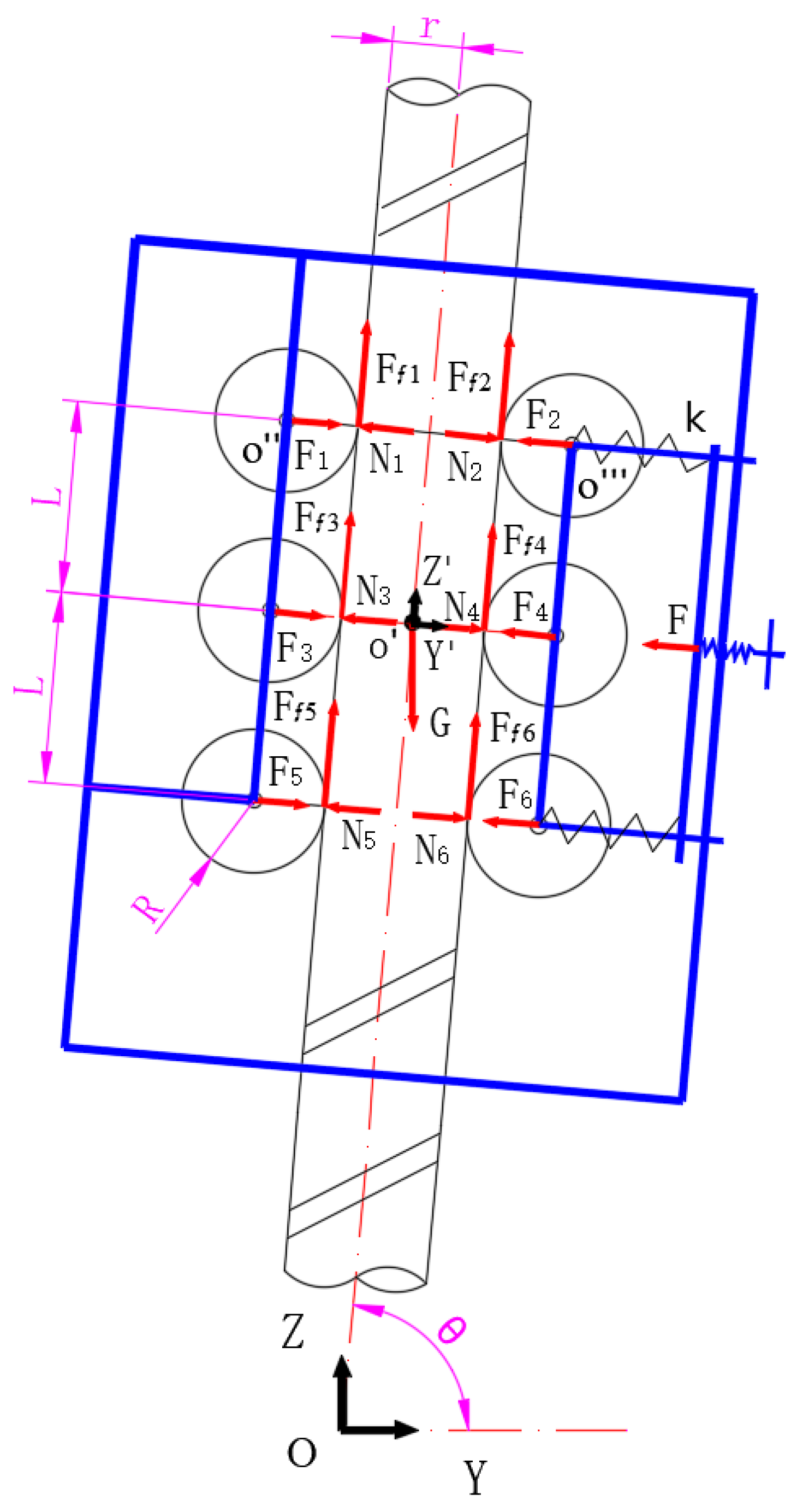
In order to analyze the balance and driving conditions of the robot, a schematic diagram of the force analysis in the hovering state of the robot is established, as shown in
Figure 5. In the figure,
is the inertial coordinate system,
is the local coordinate system of the robot,
and
are their coordinate origins,
refers to the clamping force acting on each V-shaped wheel,
denotes the normal force of the wire rope to each wheel,
represents the friction force between the wheel and the wire rope,
stands for the total weight of the robot together with the load,
is the angle between the axle of the wire rope and the Y direction of the inertial coordinate system,
signifies the clamping force applied at the handle,
is the stiffness coefficient of the spring,
is the radius of the wire rope,
denotes the radius of the V-shaped wheel, and
is the distance between the two wheels along the axis of the wire rope.
According to the force balance equations, Equations (1) and (2) can be obtained.
By considering that the structure of each wheel is symmetrical and the load is balanced, then Equations (3)–(7) can be obtained.
In Equation (7), is the normal force of the wire rope to each wheel, and μ represents the static friction coefficient between the wheel and the wire rope.
In the hover state and since
, the values of
and
can be determined by Equations (8) and (9).
According to the force analysis of wheel 1, Equations (10) and (11) can be obtained.
The clamping force
can be expressed by Equation (12).
By combining Equation (11) with Equation (12), the following is obtained:
For the robot to be able to hover on the wire rope, the clamping force
applied at its handle should satisfy the following condition:
By substituting the basic parameters of the robot as follows:
,
,
,
, the minimum value of the clamping force
is the following:
According to Hooke’s law
, the minimum distance that the screw needs to move can be determined by Equation (16).
4.1.2. Static Analysis When the Robot Has an Upward Movement Trend
When driving wheel 1 of the robot rotates clockwise, the robot tends to move upward, and its force analysis is displayed in
Figure 6a. At this point, the friction of the left wheel is upward, and the friction of the right wheel is downward. By considering the symmetry of the three pairs of left and right wheels, and in order to simplify the calculation process, the force analysis of the entire robot was considered equivalent to the force analysis of the top pair of wheels, as shown in
Figure 6b.
According to the force and moment equilibrium conditions, and assuming that the weight of the wheel is negligible, the following balance equations can be established.
where
is the center of mass of wheel 1,
stands for the center of mass of wheel 2,
is the radius of the wheel,
is the radius of the wire rope, and
,
denote the rolling friction couple moments of wheel 1 and wheel 2, respectively.
In the previous three equations, there are seven unknown values. Hence, the left and right wheels, as well as the robot framework, need to be solved separately. The force diagrams are shown in
Figure 6b.
The balance Equations (20)–(22) can be obtained from wheel 1.
The balance Equations (23)–(25) can be obtained from wheel 2.
The balance Equations (26)–(27) can be obtained from the robot framework.
When the wheel is in a critical equilibrium state, the rolling friction couple moment reaches the maximum value, which is equal to the following:
where
is the normal force of the wire rope to each wheel, and
is the rolling friction coefficient between the wheel and the wire rope.
By combining Equations (17)–(29), the following can be obtained:
By also considering that
:
Substituting the basic parameters of the robot as:
,
,
,
, the minimum value of the drive torque τ is the following:
4.1.3. Static Analysis When the Robot Has a Downward Movement Trend
When driving, wheel 1 of the robot rotates counterclockwise and the robot tends to move downward—its force analysis is displayed in
Figure 7a. At this point, the friction of the left wheel is downward, and the friction of the right wheel is upward. By considering the symmetry of the three pairs of left and right wheels, and in order to simplify the calculation process, the force analysis of the entire robot is considered equivalent to the force analysis of the top pair of wheels, as illustrated in
Figure 7b.
According to the force and moment balance conditions, and assuming that the weight of the wheel is negligible, the following equilibrium equations can be established.
Similar to the solving method of forces for the upward motion trend of the robot, the left and right wheels and the frame were taken as research objects, and the force diagrams are shown in
Figure 7b. The equilibrium equation was solved, and the following was obtained:
By substituting the basic parameters of the robot as follows:
,
,
,
, the minimum value of the drive torque
is the following:
4.2. Kinematics Analysis of the Robot
The schematic diagram of the kinematics analysis of the robot is shown in
Figure 8.
In
Figure 8,
is the initial position length of the robot on the wire rope,
refers to the climbing speed of the robot,
is the rotation speed of the motor,
is the rotation speed of the driving wheel,
denotes the number of teeth of gear 1,
is the number of teeth of gear 2,
represents the rotational angular velocity of the motor,
is the rotational angular velocity of the driving wheel, φ stands for the rotational angle of the driving wheel, and
is the angle between the axle of the wire rope and the Y direction of the inertial coordinate system.
The position equation of the robot can be expressed by Equation (38).
The speed formula of the gear transmission pairs can be expressed by the following expression:
The rotation angle φ of driving wheel 1 can be calculated as follows:
According to Equation (38) and Equation (40), the position equation of the robot can be obtained as the following:
The velocity equation of the robot can be obtained as follows:
The acceleration equation of the robot is obtained as the following:
By substituting the basic parameters of the robot as follows:
= 25,
= 30,
= 90°,
= 26 mm, and
= 23 r/min, the theoretical value of the climbing speed of the robot is the following:
5. Control Architecture
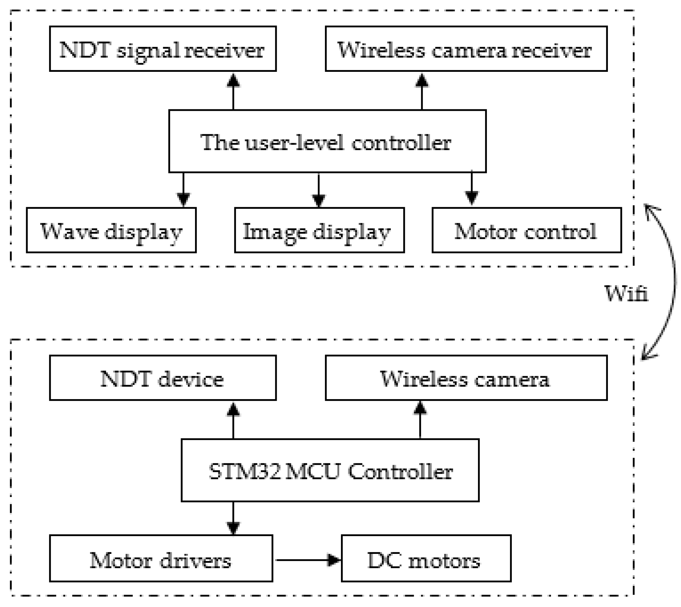
The current climbing robot can carry cameras and NDT equipment to detect defects in wire ropes. The electronic architecture of the WRR-II platform is presented in
Figure 9. The hardware control box is depicted in
Figure 10. The control system consists of two main components, namely, the user-level controller and the low-level controller. The user-level controller is on the Tablet PC platform, and it provides the user interface and data transmission from the climbing robot. The low-level controller is based on the STM32F407ZET6 main control unit (MCU), which controls the motion of the DC motors and the peripheral devices (surveillance camera, extended NDT device, etc.). The communication between the two levels was set through a Wi-Fi module. The user interface (UI) was developed based on Qt software. The robot was instructed to move upward and downward by the UI. In order to reduce the weight of the robot, the power supply was provided from the external module in our current system.
6. Experiments
In order to verify the rationality of both the design scheme and the mechanical analysis of the robot, a prototype robot was built (WRR-II), as shown in
Figure 11. In order to reduce the weight, except for the DC motor, chain drive mechanism, and V-shaped rubber wheel, the rest of the robot is made of aluminum alloy. The total mass of the robot is 3.8 kg, and the structural size of the robot is 250 × 150 × 300 mm (L × W × H).
In order to simulate the working scene of the outdoor sluice, an experimental gantry with a height of 2 m and a width of 1.2 m was built, as illustrated in
Figure 11a. Three steel wire ropes were erected on the gantry, with the following diameters: φ10 mm, φ14 mm, and φ10 mm. A φ10 mm wire rope on the far right is adjustable for tightness, and was coated with grease. The leftmost φ10 mm and the middle φ14 mm wire ropes were fixed at both the top and bottom, and were not greased. The distance between the adjacent wire ropes was 200 mm. This arrangement can simulate and test the climbing performance of the robot under different working conditions of the wire rope.
The installation and disassembly process of the robot is very simple since it only requires opening the two pull buttons on the front of the robot to separate the left and right frames of the robot around the hinges, putting it on the wire rope, and then fastening the pull buttons. Finally, the clamping force between the wheels of the driven trolley and the wire rope is adjusted by the position adjustment mechanism. Thus, the robot can hover on the wire rope without slipping. The whole operation process can be completed within 1 min by a single person. The disassembly process is exactly the reverse of the previously described installation process.
To validate the performance of the robot, the project team carried out a series of experiments, such as a climbing speed test, a climbing adaptability test, a load capacity test, and an obstacle negotiation ability test.
6.1. Climbing Speed Test
In the case that no load is present, the climbing speed of the robot was calculated by measuring the time required for the robot to climb 1 m on φ14 mm grease-free wire rope several times. Through these experiments, it was found that when the output speed of the motor was 23 r/min, the robot can climb up at a speed of 40 mm/s, and move downward at a speed slightly higher (45 mm/s). Compared with the climbing speed of the first-generation climbing robot WRR-I developed in the early stages (26 mm/s) [
31], the speed performance was significantly improved. However, when compared with the theoretical calculation speed of 52 mm/s the actual climbing speed of the robot was reduced, due to a certain slippage between the rubber wheel and the wire rope during the climbing process.
6.2. Climbing Adaptability Test
In order to test the climbing adaptability of the robot, it was installed on the wire ropes under five different working conditions, as shown in
Figure 12. The climbing stroke was equal to 1 m up and down, and the test results are shown in
Table 2.
As can be seen from
Table 2, the robot can stably climb on the wire rope, under various conditions. By analyzing upward climbing speeds, the robot on the non-greased wire rope was obviously faster than the one on the greased wire rope. For the same greased wire rope, the robot climbing speed was slightly faster when the two ends were fixed, when compared to the one with a single end. Regarding the angle, it is possible to conclude that the robot’s climbing speed was slightly faster in the vertical case than one in the inclined case. During the downward process, the downward speed under various working conditions is generally consistent, and no obvious differences can be found. In addition, the change in the wire rope diameter has some impact on the climbing speed of the robot. As the diameter of the wire rope increased, the climbing speed increased slightly.
6.3. Load Capacity Test
In order to verify the load capacity of the robot, the robot was installed on a φ14 mm non-greased wire rope that was fixed at both ends, where loads of different weights are added on the robot, as depicted in
Figure 13, with the climbing speed results shown in
Figure 14. Looking at the results, it is clear that as the load increases, the upward speed of the robot slows down. When the load exceeds 10 kg, the motor is overloaded and does not move during the upward process of the robot. Regarding the downward process, the speed of the robot was relatively stable, independently of the load’s weight.
The climbing speed of the robot varies for different wire rope inclination angles and different load weights, and its relationship is depicted in
Figure 15. The robot was installed on a φ10 mm non-greased wire rope that was fixed at both ends, where loads of different weights ranging from 0 to 5 kg were added onto the robot. The range of the wire rope inclination angles was from 50° to 90°. As shown in
Figure 15, the climbing speed of the robot decreased significantly with the increase in load weights. For the same load, with the decrease of the inclination angle, the climbing speed of the robot decreases first and then grows.
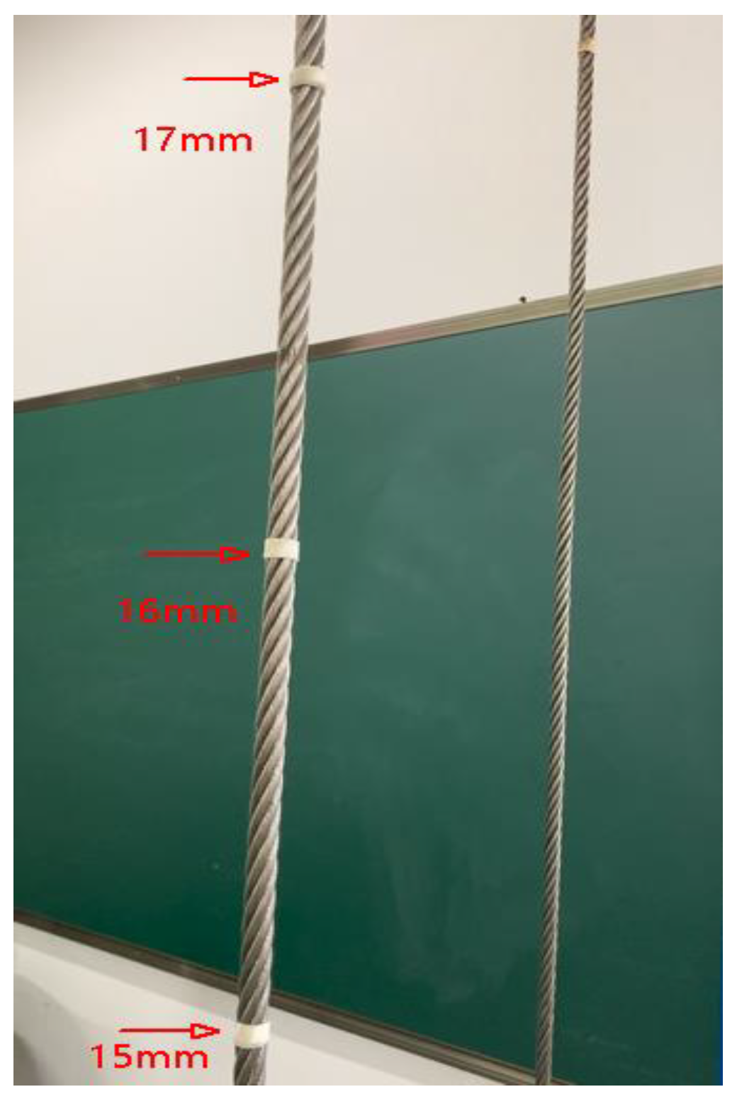
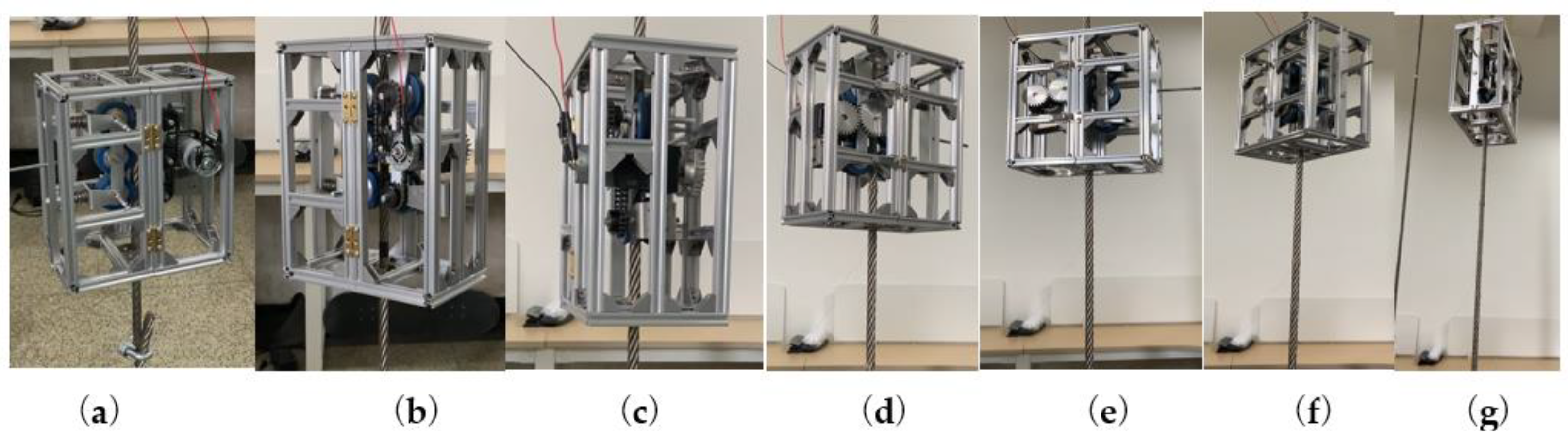
6.4. Obstacle Negotiation Ability Test
In order to test the robot’s ability to cross obstacles, the φ14 mm wire rope was wrapped with tape to form three steps of different diameters, as shown in
Figure 16. The diameters of the three steps were φ15 mm, φ16 mm, and φ17 mm, with their spacing equal to 30 mm. During the ascending process (as shown in
Figure 17), the robot successfully passed three steps of different diameters but during the descending process, the robot briefly slipped at the φ17 mm step, barely passing at the end. This also reflects that wheeled climbing robots have certain deficiencies when trying to overcome obstacles.
6.5. Performance Comparison of the Robots
Table 3 lists some performance parameters of various rope-climbing robots. Compared with these climbing robots (WRR-I, WRC
2IN-I, WRC
2IN-II, as presented in
Table 3), WRR-II is more competent for climbing small diameter wire ropes, and has better climbing performance.
7. Conclusions and Future Work
Both cleaning and maintenance of wire ropes have always been a major problem in the industry since there are problems regarding high labor intensity and high safety risks. The wire rope used for sluices has a small diameter and a narrow operating range, it is installed almost vertically, and is covered with grease of different degrees of hardening, which bring about greater cleaning and maintenance difficulty. Compared with the first-generation pneumatic peristaltic wire rope climbing robot WRR-I, this work proposed and described a new system, a six-wheel wire rope climbing robot (WRR-II). Under the condition of its own weight of 3.8 kg, the robot can carry a maximum of 8 kg of working tools for online laser cleaning and maintenance of steel wire ropes and visual safety inspection, thus it has a good application prospect.
The six-wheeled wire rope climbing robot proposed in this work, not only has a simple structure, a simple control, and a stable climbing speed, but it also has a large contact area and little influence on the wheel deformation of the crawler climbing robot. It was shown that it can adapt to climbing tasks of wire ropes with different diameters and different lubrication states. The theoretical analysis of the statics and kinematics of the robot, as well as the performance test of the prototype, verify the rationality and feasibility of the designed scheme. During the experiments performed with the prototype, it was also found that the V-shaped rubber wheel would have a certain slip when climbing on the surface of the wire rope covered with grease.
In future work, the project team will further optimize the structure of the rubber wheel and increase the claw-thorn structure. Therefore, it can be well adapted to the task of climbing wire rope with grease, as well as to improve the load capacity of the robot. Some new methods that have the potential to make soft and slight robots are considered to be used to improve the robot’s climbing performance, such as a fluidic rolling robot using voltage-driven oscillating liquid [
32], and an active sorting of droplets by using an electro-conjugate fluid micropump [
33]. What is more, it is necessary to select actual rural river sluices and coastal river sluices for outdoor field experiments, to further verify the climbing ability of the designed robot. In addition, the influence of laser cleaning devices and non-destructive testing devices on the climbing performance of the robot will also be studied, as well as the impact of wire rope maintenance.


