
Morphing Wing Based on Trigonal Bipyramidal Tensegrity Structure and Parallel Mechanism


Abstract
1. Introduction
2. Configuration Design of Morphing Wing
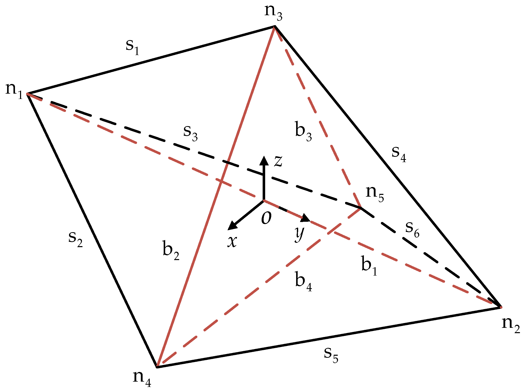
2.1. Design of Tensegrity Structure
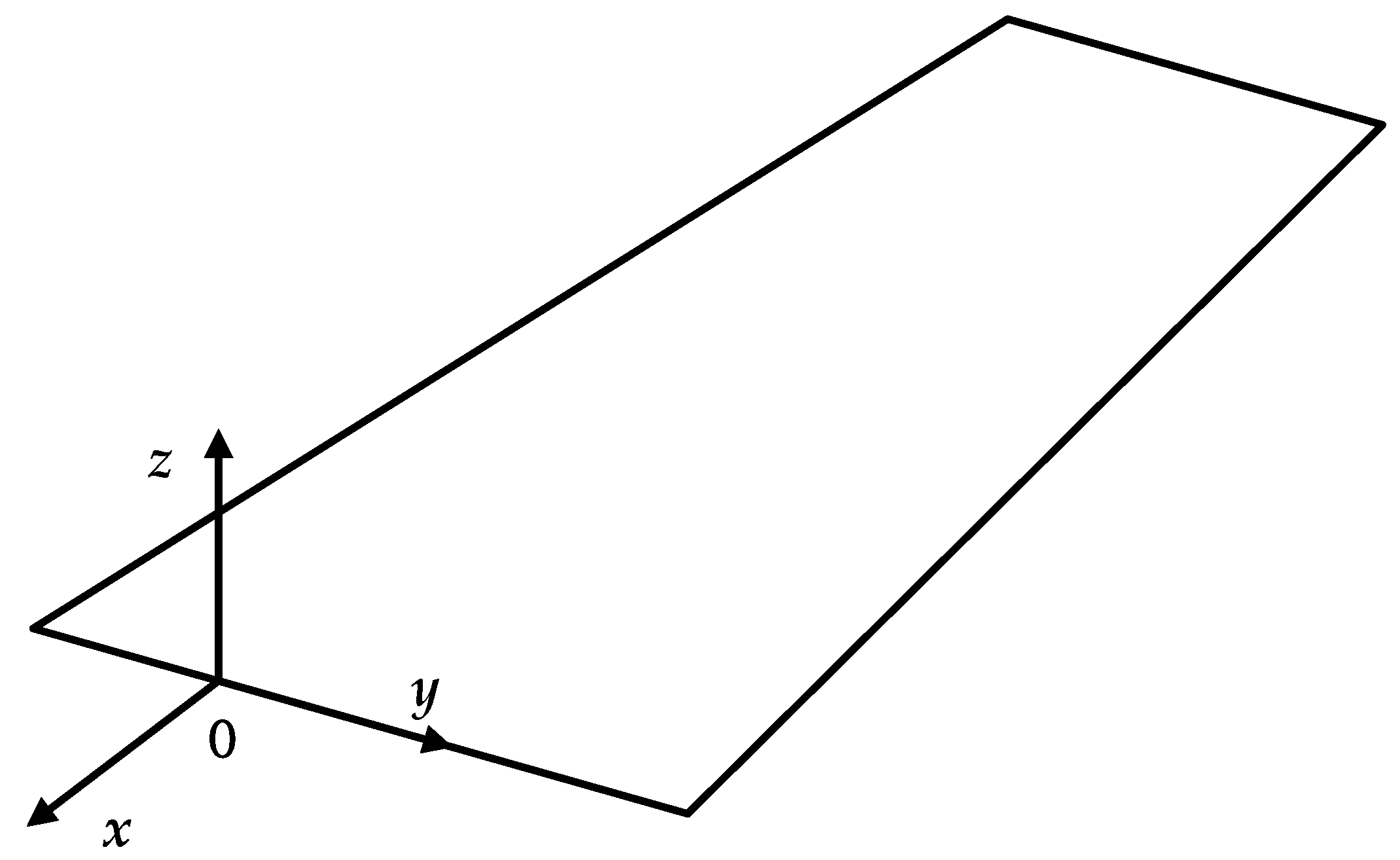
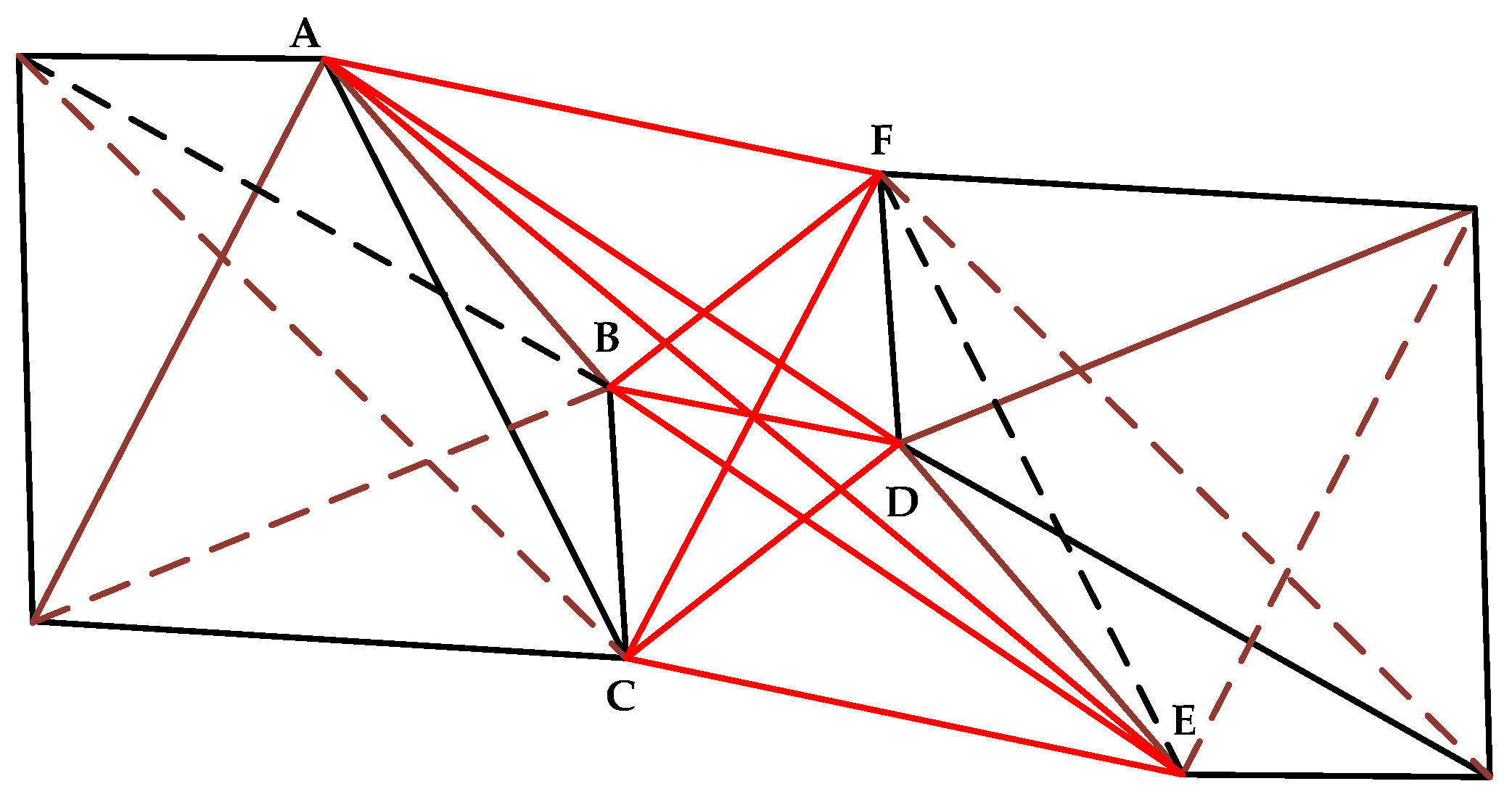
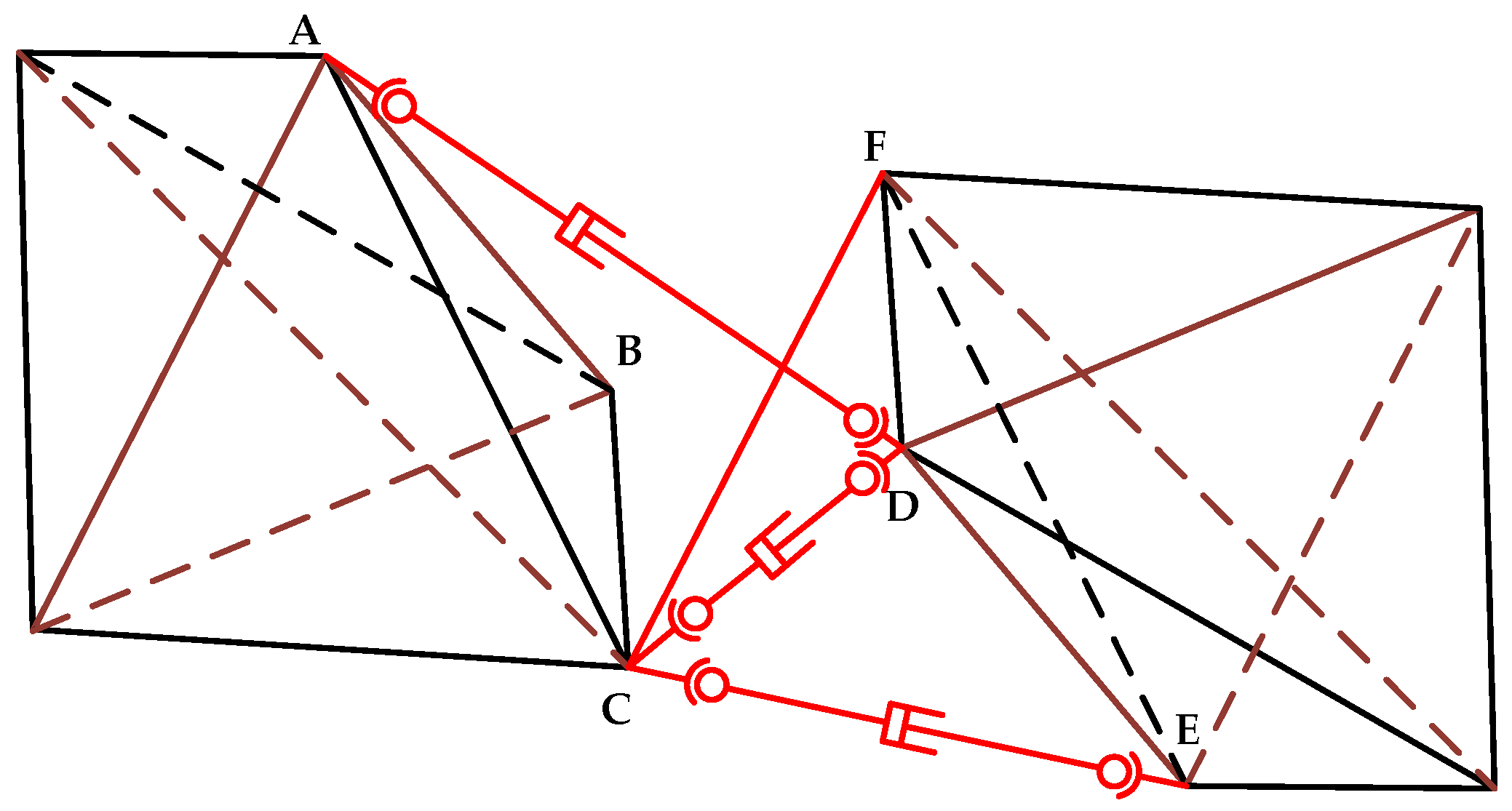
2.2. Design of Wing Morphing Mechanism
3. Kinematic Characteristics of the 4SPS-RS Parallel Mechanism
3.1. Degree of Freedom
3.2. Inverse Solution
3.3. Jacobian Matrix
4. Stiffness Analysis of Morphing Wing
4.1. Stiffness Analysis of Tensegrity Structure
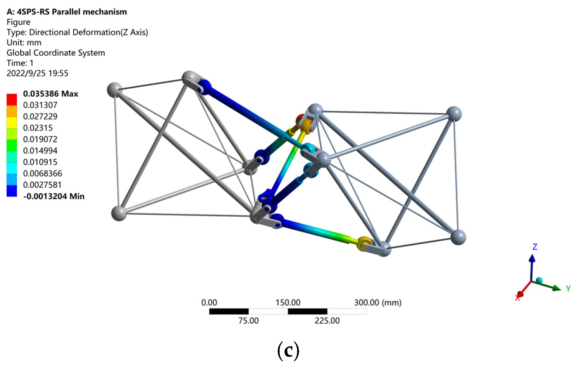
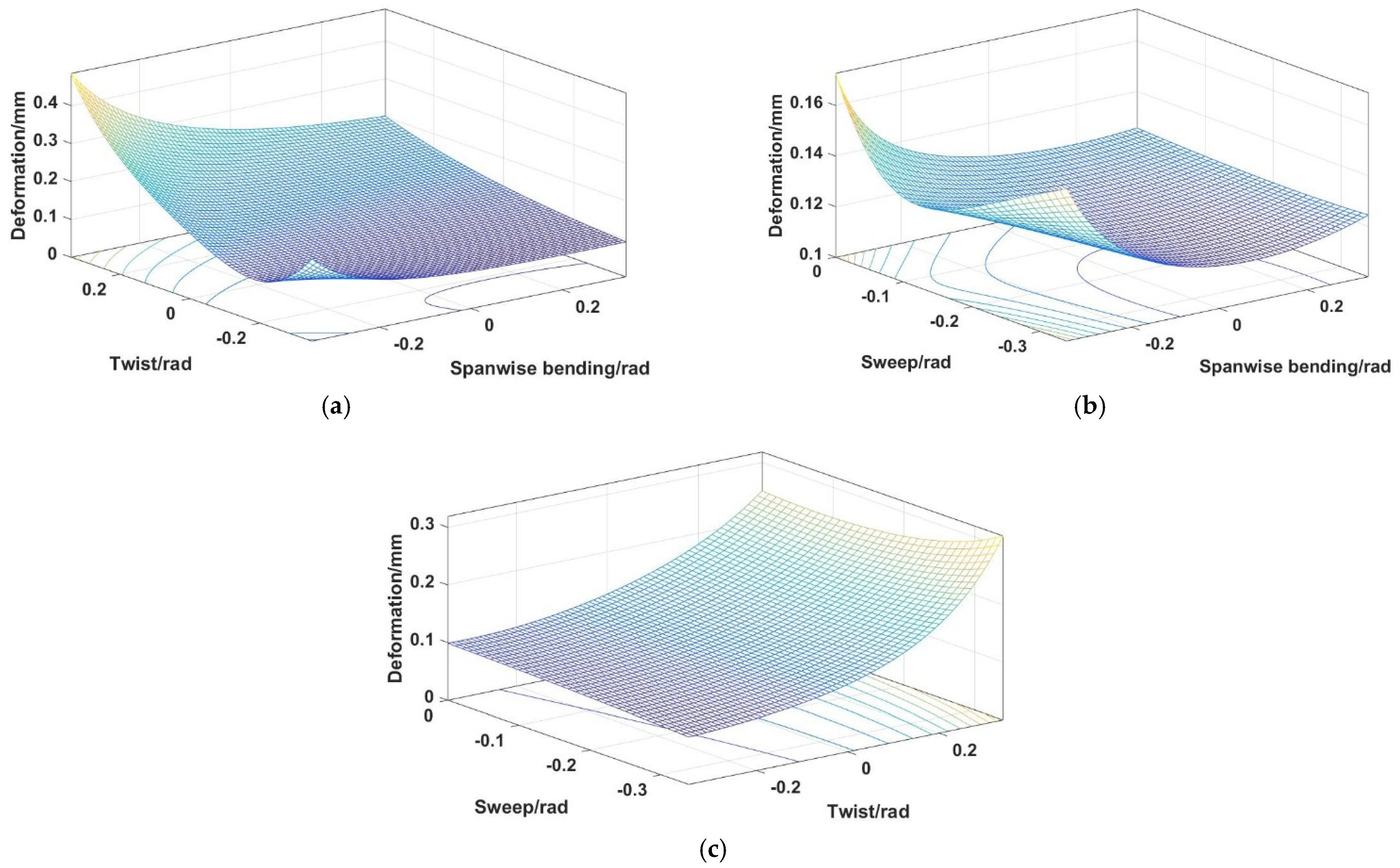
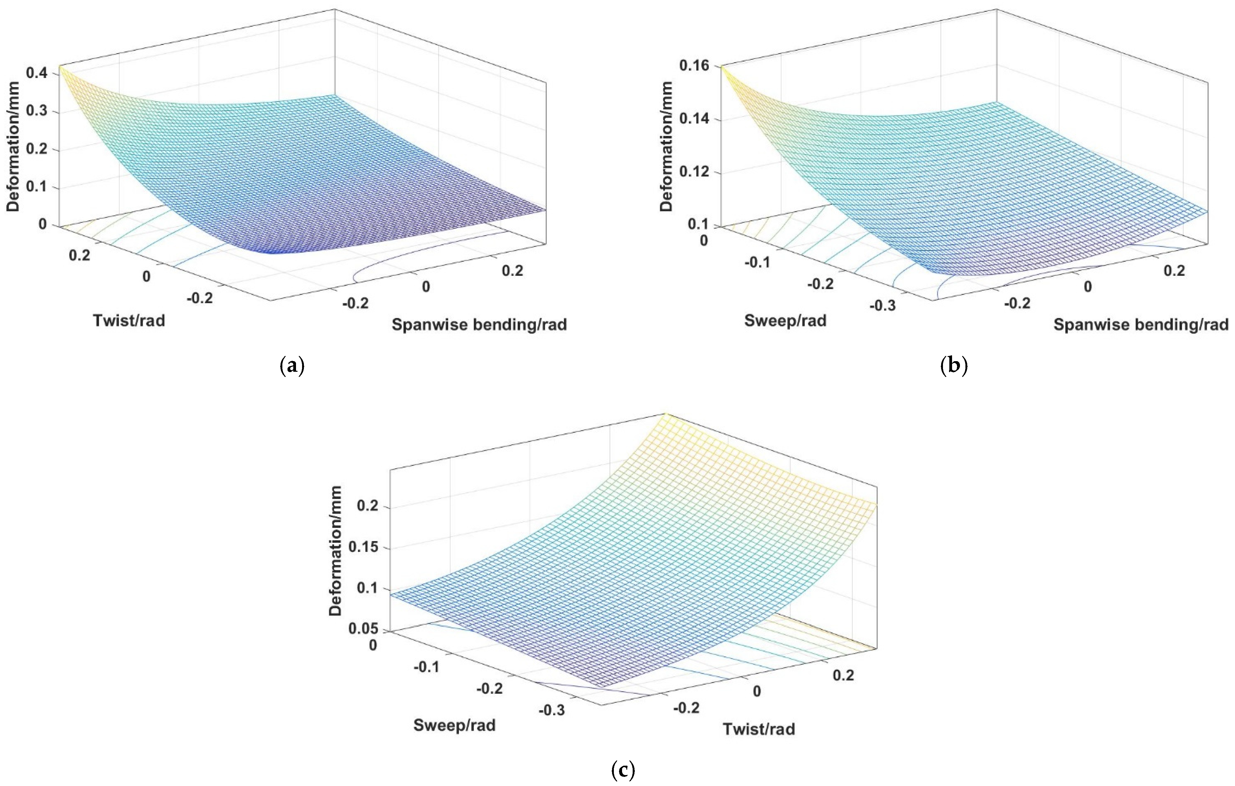
4.2. Stiffness Analysis of the 4SPS-RS Parallel Mechanism
5. Discussion and Conclusions
Author Contributions
Funding
Institutional Review Board Statement
Informed Consent Statement
Data Availability Statement
Conflicts of Interest
Abbreviations
| N | Node coordinate matrix |
| ni | Node coordinate |
| Rigid rod connection matrix | |
| Flexible cable connection matrix | |
| B | Rigid rod position direction matrix |
| S | Flexible cable position direction matrix |
| A | Node force balance matrix |
| s | Self-stress modal number |
| m | Displacement modal number |
| M | Degree of freedom |
| h | The number of active components |
| fi | Degree of freedom of the i-th kinematic pair |
| v | The number of overconstraints |
| PG | The coordinates of point P in the fixed coordinate system |
| PH | The coordinates of point P in the moving coordinate system |
| T | Attitude transformation matrix |
| Rot | Rotation transformation matrix |
| Trans(OG,F) | Displacement transformation matrix from OG to F |
| The joint motion spiral | |
| The amplitude of the j-th joint velocity of the i-th branch | |
| The motion screw of the j-th joint of the i-th branch | |
| Constraint force provided by CF branch | |
| Jy | Constraint Jacobian matrix |
| Jq | Driving force Jacobian matrix |
| J | 4SPS-RS mechanism Jacobian matrix |
| QV | Drive branch velocity matrix |
| QF | Driving force matrix |
| The force at the nodes n3 caused by rod b2 | |
| Tangent stiffness matrix | |
| Theoretical deformation of tensegrity structure when the material is structural steel | |
| Simulation deformation of tensegrity structure when the material is structural steel | |
| Kg | The axial stiffness of the screw |
| Km | The axial stiffness of the ball nut |
| Kq | The drive branch stiffness |
| KCF1 | The axial tensile stiffness of central rod |
| Kl | The branch stiffness matrix |
| K | Stiffness matrix |
| Theoretical deformation of 4SPS-RS parallel mechanism when the material is structural steel | |
| Simulation deformation of 4SPS-RS parallel mechanism when the material is structural steel |
References
- Ameduri, S.; Concilio, A. Morphing Wings Review: Aims, Challenges, and Current Open Issues of a Technology. Proc. Inst. Mech. Eng. Part C J. Mech. Eng. Sci. 2020, 0, 095440622094442. [Google Scholar] [CrossRef]
- Ajaj, R.M.; Parancheerivilakkathil, M.S.; Amoozgar, M.; Friswell, M.I.; Cantwell, W.J. Recent Developments in the Aeroelasticity of Morphing Aircraft. Prog. Aerosp. Sci. 2021, 120, 100682. [Google Scholar] [CrossRef]
- Barbarino, S.; Bilgen, O.; Ajaj, R.M.; Friswell, M.I.; Inman, D.J. A Review of Morphing Aircraft. J. Intell. Mater. Syst. Struct. 2011, 22, 823–877. [Google Scholar] [CrossRef]
- Moosavian, A.; Xi, F.; Hashemi, S.M. Optimal Configuration Design for the Variable Geometry Wing-Box. J. Aircr. 2014, 51, 811–823. [Google Scholar] [CrossRef]
- Finistauri, A.D.; Xi, F.; Walsh, P. Discretization Method for the Development of a Modular Morphing Wing. J. Aircr. 2012, 49, 116–125. [Google Scholar] [CrossRef]
- Moosavian, A.; Xi, F.; Hashemi, S.M. Design and Motion Control of Fully Variable Morphing Wings. J. Aircr. 2013, 50, 1189–1201. [Google Scholar] [CrossRef]
- Lai, G.; Plummer, A.; Cleaver, D. Distributed Actuation and Control of a Morphing Tensegrity Structure. J. Dyn. Syst. Meas. Control 2020, 142, 071006. [Google Scholar] [CrossRef]
- Lai, G.; Plummer, A.R.; Cleaver, D.J.; Zhou, H. Parallel Kinematic Mechanisms for Distributed Actuation of Future Structures. J. Phys. Conf. Ser. 2016, 744, 012169. [Google Scholar] [CrossRef]
- Zhou, H.; Plummer, A.; Cleaver, D. Closed Loop Position and Pre-Stress Control for a Morphing Aircraft Wing with Distributed Multi-Axis Pneumatic Actuation. In Proceedings of the BATH/ASME 2018 Symposium on Fluid Power and Motion Control, Bath, UK, 12 September 2018; American Society of Mechanical Engineers: New York, NY, USA, 2018; p. V001T01A031. [Google Scholar]
- Yang, G.; Guo, H.; Xiao, H.; Bai, Y.; Liu, R. Design and Analysis of a Variable-Sweep Morphing Wing for UAV Based on a Parallelogram Mechanism. In Proceedings of the 2021 IEEE International Conference on Robotics and Biomimetics (ROBIO), Sanya, China, 6–9 December 2021; pp. 1650–1655. [Google Scholar]
- Hui, Z.; Zhang, Y.; Chen, G. Aerodynamic Performance Investigation on a Morphing Unmanned Aerial Vehicle with Bio-Inspired Discrete Wing Structures. Aerosp. Sci. Technol. 2019, 95, 105419. [Google Scholar] [CrossRef]
- Jenett, B.; Calisch, S.; Cellucci, D.; Cramer, N.; Gershenfeld, N.; Swei, S.; Cheung, K.C. Digital Morphing Wing: Active Wing Shaping Concept Using Composite Lattice-Based Cellular Structures. Soft Robot. 2017, 4, 33–48. [Google Scholar] [CrossRef]
- Pham, N.K.; Peraza Hernandez, E.A. Modeling and Design Exploration of a Tensegrity-Based Twisting Wing. J. Mech. Robot. 2021, 13, 031019. [Google Scholar] [CrossRef]
- Luo, B.; Cui, W.; Li, W. Active and Robust Twisting Morphing Wings with Geometric Constraints for Flying or Swimming Robots. IEEE/ASME Trans. Mechatron. 2022, 1–6. [Google Scholar] [CrossRef]
- Zhang, H.; Zhang, Z.; Song, C.; Yang, C. A Morphing Wing with Cellular Structure of Non-Uniform Density. Smart Mater. Struct. 2021, 30, 105005. [Google Scholar] [CrossRef]
- Boston, D.M.; Phillips, F.R.; Henry, T.C.; Arrieta, A.F. Spanwise Wing Morphing Using Multistable Cellular Metastructures. Extrem. Mech. Lett. 2022, 53, 101706. [Google Scholar] [CrossRef]
- Parancheerivilakkathil, M.S.; Haider, Z.; Ajaj, R.M.; Amoozgar, M. A Polymorphing Wing Capable of Span Extension and Variable Pitch. Aerospace 2022, 9, 205. [Google Scholar] [CrossRef]
- Yun, Z.; Feng, Y.; Tang, X.; Chen, L. Analysis of Motion Characteristics of Bionic Morphing Wing Based on Sarrus Linkages. Appl. Sci. 2022, 12, 6023. [Google Scholar] [CrossRef]
- Ajaj, R.M.; Jankee, G.K. The Transformer Aircraft: A Multimission Unmanned Aerial Vehicle Capable of Symmetric and Asymmetric Span Morphing. Aerosp. Sci. Technol. 2018, 76, 512–522. [Google Scholar] [CrossRef]
- Elelwi, M.; Calvet, T.; Botez, R.M.; Dao, T.-M. Wing Component Allocation for a Morphing Variable Span of Tapered Wing Using Finite Element Method and Topology Optimisation—Application to the UAS-S4. Aeronaut. J. 2021, 125, 1313–1336. [Google Scholar] [CrossRef]
- Wang, J.; Zhao, Y.; Xi, F.; Tian, Y. Design and Analysis of a Configuration-Based Lengthwise Morphing Structure. Mech. Mach. Theory 2020, 147, 103767. [Google Scholar] [CrossRef]
- Zhao, Y.; Xi, F.; Tian, Y.; Wang, W.; Li, L. Design of a Planar Hyper-Redundant Lockable Mechanism for Shape Morphing Using a Centralized Actuation Method. Mech. Mach. Theory 2021, 165, 104439. [Google Scholar] [CrossRef]
- Myszka, D.H.; Joo, J.J. A Study on the Structural Suitability of Tensegrity Structures to Serve as Morphing Aircraft Wings. In Proceedings of the 42nd Mechanisms and Robotics Conference, American Society of Mechanical Engineers. Quebec, QC, Canada, 26–29 August 2018; Volume 5B, p. V05BT07A005. [Google Scholar]
- Merle–t, J.P. Parallel Robots; Springer New York Inc.: New York, NY, USA, 2005; ISBN 978-1-4020-4132-7. [Google Scholar]
- Brahmia, A.; Kelaiaia, R.; Chemori, A.; Company, O. On Robust Mechanical Design of a PAR2 Delta-Like Parallel Kinematic Manipulator. J. Mech. Robot. 2022, 14, 011001. [Google Scholar] [CrossRef]
- Pellegrino, S. Analysis of Prestressed Mechanisms. Int. J. Solids Struct. 1990, 26, 1329–1350. [Google Scholar] [CrossRef]
- Guest, S. The Stiffness of Prestressed Frameworks: A Unifying Approach. Int. J. Solids Struct. 2006, 43, 842–854. [Google Scholar] [CrossRef]
- Masic, M.; Skelton, R.E.; Gill, P.E. Algebraic Tensegrity Form-Finding. Int. J. Solids Struct. 2005, 42, 4833–4858. [Google Scholar] [CrossRef]
- Krivošej, J.; Šika, Z. Optimization and Control of a Planar Three Degrees of Freedom Manipulator with Cable Actuation. Machines 2021, 9, 338. [Google Scholar] [CrossRef]
- Pham, M.T.; Yeo, S.H.; Teo, T.J.; Wang, P.; Nai, M.L.S. A Decoupled 6-DOF Compliant Parallel Mechanism with Optimized Dynamic Characteristics Using Cellular Structure. Machines 2021, 9, 5. [Google Scholar] [CrossRef]
- Choi, W.; Takeda, Y. Geometric Design and Prototyping of a (2-RRU)-URR Parallel Mechanism for Thumb Rehabilitation Therapy. Machines 2021, 9, 50. [Google Scholar] [CrossRef]
- Fomin, A.; Antonov, A.; Glazunov, V.; Carbone, G. Dimensional (Parametric) Synthesis of the Hexapod-Type Parallel Mechanism with Reconfigurable Design. Machines 2021, 9, 117. [Google Scholar] [CrossRef]
- Jiang, D.; Zheng, T.; Yang, G.; Tian, Y.; Fang, Z.; Li, H.; Zhang, C.; Ye, H. Design and Analysis of a Stiffness-Enhanced 3-PPS Parallel Mechanism for Fault-Tolerant Underwater Vectored Thrusters. Machines 2022, 10, 88. [Google Scholar] [CrossRef]
- Gosselin, C. Stiffness Mapping for Parallel Manipulators. IEEE Trans. Robot. Automat. 1990, 6, 377–382. [Google Scholar] [CrossRef]
- Zhu, C.; Liu, X.; Liu, W. Research on Structural Optimization of 3-TPT Parallel Mechanism Based on Stiffness Characteristics. Mech. Based Des. Struct. Mach. 2021, 49, 256–270. [Google Scholar] [CrossRef]


| External Load | AD | BE | CD | CE |
|---|---|---|---|---|
| lift | compression | subject | subject | subject |
| resistance | compression | subject | compression | compression |
| 1 | 2 | 3 | 4 | 5 | 6 | 7 | 8 | 9 | |
|---|---|---|---|---|---|---|---|---|---|
| Lt | 180 | 190 | 200 | 210 | 220 | 230 | 240 | 250 | 260 |
| Lp | 100 | 110 | 120 | 120 | 130 | 130 | 140 | 140 | 150 |
| 10 | 11 | 12 | 13 | 14 | 15 | 16 | 17 | 18 | |
|---|---|---|---|---|---|---|---|---|---|
| Lt | 270 | 280 | 290 | 300 | 310 | 320 | 330 | 340 | 350 |
| Lp | 160 | 160 | 170 | 170 | 180 | 190 | 190 | 200 | 200 |
| Parameter | Density(kg/m3) | Elastic Modulus (MPa) | Poisson Ratio |
|---|---|---|---|
| Value | 2810 | 71,000 | 0.33 |
| Parameter | Density (kg/m3) | Elastic Modulus (MPa) | Poisson Ratio |
|---|---|---|---|
| Value | 1800 | 28,000 | 0.34 |
Publisher’s Note: MDPI stays neutral with regard to jurisdictional claims in published maps and institutional affiliations. |
© 2022 by the authors. Licensee MDPI, Basel, Switzerland. This article is an open access article distributed under the terms and conditions of the Creative Commons Attribution (CC BY) license (https://creativecommons.org/licenses/by/4.0/).
Share and Cite
Sun, J.; Li, X.; Xu, Y.; Pu, T.; Yao, J.; Zhao, Y. Morphing Wing Based on Trigonal Bipyramidal Tensegrity Structure and Parallel Mechanism. Machines 2022, 10, 930. https://doi.org/10.3390/machines10100930
Sun J, Li X, Xu Y, Pu T, Yao J, Zhao Y. Morphing Wing Based on Trigonal Bipyramidal Tensegrity Structure and Parallel Mechanism. Machines. 2022; 10(10):930. https://doi.org/10.3390/machines10100930
Chicago/Turabian StyleSun, Jian, Xiangkun Li, Yundou Xu, Tianyue Pu, Jiantao Yao, and Yongsheng Zhao. 2022. "Morphing Wing Based on Trigonal Bipyramidal Tensegrity Structure and Parallel Mechanism" Machines 10, no. 10: 930. https://doi.org/10.3390/machines10100930
APA StyleSun, J., Li, X., Xu, Y., Pu, T., Yao, J., & Zhao, Y. (2022). Morphing Wing Based on Trigonal Bipyramidal Tensegrity Structure and Parallel Mechanism. Machines, 10(10), 930. https://doi.org/10.3390/machines10100930