Article

Static Modelling and Analysis of a Novel Movable Tooth Drive with Logarithmic Spiral Tooth Profiles

Key Laboratory of Mechanism Theory and Equipment Design, Ministry of Education, Tianjin University, Tianjin 300354, China
*
Author to whom correspondence should be addressed.
Machines 2022, 10(10), 837; https://doi.org/10.3390/machines10100837
Submission received: 26 August 2022 / Revised: 9 September 2022 / Accepted: 19 September 2022 / Published: 21 September 2022
(This article belongs to the Section Machine Design and Theory)

Abstract

:
This paper presents a static model for a novel movable tooth drive with logarithmic spiral tooth profiles, to research contact force and load distribution during the meshing period. According to the geometric properties of the conjugate tooth profiles, their compatibility law considering the multi-tooth elastic meshing effect are investigated to reveal load distribution characteristic of the teeth. The static model of the mechanism is thus developed to systematically analyze variation in contact force during the rise travel. The results indicate that the contact force between the tooth and ring gear is proportional to the curvature radius of the contact point, and it increases exponentially and monotonically corresponding to the curvature radius of logarithmic spiral tooth profile; in the multi-tooth meshing condition, the load distribution of the teeth coincides with the ratio of the curvature radius of each contact point, and periodical pulsations of total contact force occur at the alternation of the teeth. Finally, the proposed model is validated by the FEM simulation of a prototype, and the influence of dimensional parameters is further discussed for the self-locking and force transmission characteristics of the tooth. The outcomes provide critical technical support for the static modelling and design of such transmission mechanism.

1. Introduction

Multi-tooth meshing is the crucial structural characteristic of heavy load-bearing gear transmissions, and mechanic modelling of the over-constrained transmission systems has drawn continuous interest. At present, cycloid and harmonic drives, based on the cycloidal, involute, or double-circular-arc tooth profiles, etc., are prevailing high-precision products that have been extensively applied in industrial and engineering fields [1]. Tremendous efforts have been devoted to relevant research on force and load distribution analysis.
Over recent decades, Kudrijavcev [2] and Malhotra et al. [3] studied the static modelling of a cycloid-pinwheel transmission. The former [2] proposed an accurate force model of a cycloid-pin gear with the ideal dimensions based on the assumption of constant output torque, providing references for the subsequent calculation of cycloid-pin meshing stiffness [4]. The latter [3] investigated the forces of various elements and the influence of design parameters on the contact stress. Similarly, Gorla et al. [5] developed a simplified procedure to calculate the load distribution on the components of an innovative cycloid speed reducer, and conducted an experiment to validate the theoretical analysis results. Li et al. [6] established an analytical model based on the loaded tooth contact analysis in the presence of clearances and eccentricity errors, making the load distribution prediction more precise. Hidaka et al. [7] presented a systematic force-displacement model of RV reducer by means of equivalent springs or clearances to release the over-constraints of components, and the modelling method laid significant technical foundation for mechanical investigations of such over-constrained transmission systems. Moreover, numerous scholars have deepened studies by considering different influential factors of load distribution, such as frictions between cycloidal gear and pins [8], dynamic contact and collision of pinwheel [9,10], elasticities of crankshafts and cycloidal gear [11], as well as assembly clearances and tooth profile modifications [12,13]. Furthermore, relevant research on the FEA of multi-tooth meshing characteristics gained deep insight [14,15,16]. Kim et al. [14] simulated the influence of elastic deformations of the cycloidal gear on the meshing forces by a semi-analytical method. Li [15] refined actual load and contact stress distribution on the bushes and bearing rollers in the finite element model, aiming for convenient and accurate strength calculations and evaluation. Blagojevic et al. [16] introduced a new design for a two-stage cycloid speed reducer and an approximate approach for the load distribution analysis based on the previous work [3]; the FEA model of contact stress was validated by the experimental results. It is worth mentioning that Xu et al. [17] presented a multi-tooth meshing model by discretizing tooth profiles with modification and bearing clearances considered, allowing for the contact loads to be calculated precisely by the determined contact point and depth, and a customized program was developed for improving the design initiative and analysis accuracy.
Harmonic drive, as another typical reducer characterized with multi-tooth meshing, transmits force and motion through periodic elastic deformations controlled by the flexspline (FS) and wave generator (WG) [18]. Kayabasi et al. [19] conducted a computational stress–strain simulation of the FS via FEA and obtained the optimum shape of the FS teeth to maximize fatigue life. Li et al. [20] defined the objective function to minimize the circumferential stress of the FS through an optimization model of the WG profile. Zhu et al. [21] established the theoretical model of contact force between rolling elements and outer ring, based on three bending moment equations, and studied the mechanical characteristics of the FS with the aid of FEA. Pacana [22] studied the effect of the structural form on the stress distribution of the FS and presented stress diagrams in longitudinal intersections for susceptible wheels of different shapes for direct comparison. As a parallel session, considerable attention has been paid to the experimental studies [23,24,25]. Tjahjowidodo et al. [23] developed two test setups comprising the high- and low-load torque harmonic drives, respectively, and the hysteresis tests with different loads were implemented to validate the torsional compliance model. Ma et al. [24] employed an experimental method to investigate the effect of the driving speed on the deformation properties of the FS. Apart from these attempts to optimize design parameters of the FS, some other researchers have also concentrated on the WG performances. Chen et al. [26] presented a mechanical analysis method to calculate the stretch in the neutral line of the FS under the action of four-roller WG. Xiong et al. [27] developed a universal static analysis model to calculate the roller load distribution of flexible bearings, considering the numbers of rollers and the shape of WG cam. Mahanto et al. [28] utilized the finite element and experimental methods to investigate the stress–strain distribution pattern in the FS considering the insertion of conventional and split WG cam, respectively. Yague-Spaude et al. [29] compared the mechanical performance of WG with four different geometries, and the results showed that the lower average value of maximum von Mises and tensile stresses was achieved with the simplified and parabolic geometries. In addition, Xu et al. [30,31] studied the operation principle of an electromagnetic harmonic drive and deduced the displacement and output torque equations of the flexible ring under magnetic forces.
Throughout the above-mentioned literature, lots of valuable contributions have been made to the mechanic studies of cycloid and harmonic drives, providing general methods for relevant research into various over-constrained gear transmission systems. Yet it may be pointed out that the multi-tooth elastic contact analysis of different transmissions still needs to be further investigated, considering the distinctive meshing characteristics of the conjugate tooth profiles and the topologies of kinematic pairs.
It is worth noting that a novel type of movable tooth drive has been proposed that is characterized by a logarithmic spiral tooth profile [32]. Its structure is different from traditional movable tooth drives by using balls or rollers as transmission mediums. Under the working conditions, the innovative tooth geometry makes the almost full surface contact possible, unlike cycloidal or involute tooth profiles that only create a linear contact. Therefore, the novel drive can bear more loads and has higher rigidity. It is believed to exhibit broad application prospects in the field with heavy load requirements, such as machine tools, petroleum drilling platforms, industrial robots, etc. In the movable tooth drive, several independent dynamic teeth interlock simultaneously instead of an integral gear. All these features make the force analysis and multi-tooth meshing effect quite different from the previous studies, and little reported work in the open literature can be found with respect to the force characteristics of such a tooth profile.
In response to the insufficiency, it is of great significance to investigate the static modelling of the mechanism and compatibility law of the conjugate tooth profile, especially taking into consideration geometric properties of logarithmic spiral and multi-tooth meshing effect. The remainder of this paper is organized as follows: After this introduction, the mathematical properties of logarithmic spiral and the structure and transmission principle of the mechanism are briefly introduced in Section 2. Next, the profile equations of the logarithmic spiral conjugate tooth profile and wave generator are established in Section 3. Then, Section 4 studies the multi-tooth meshing load distribution characteristic and develops the static model of the mechanism. Subsequently, the validity of the presented model is verified by the FEM simulation in Section 5. On this basis, Section 6 implements analysis of self-locking and force transmission characteristics of the teeth, before conclusions are drawn in Section 7.

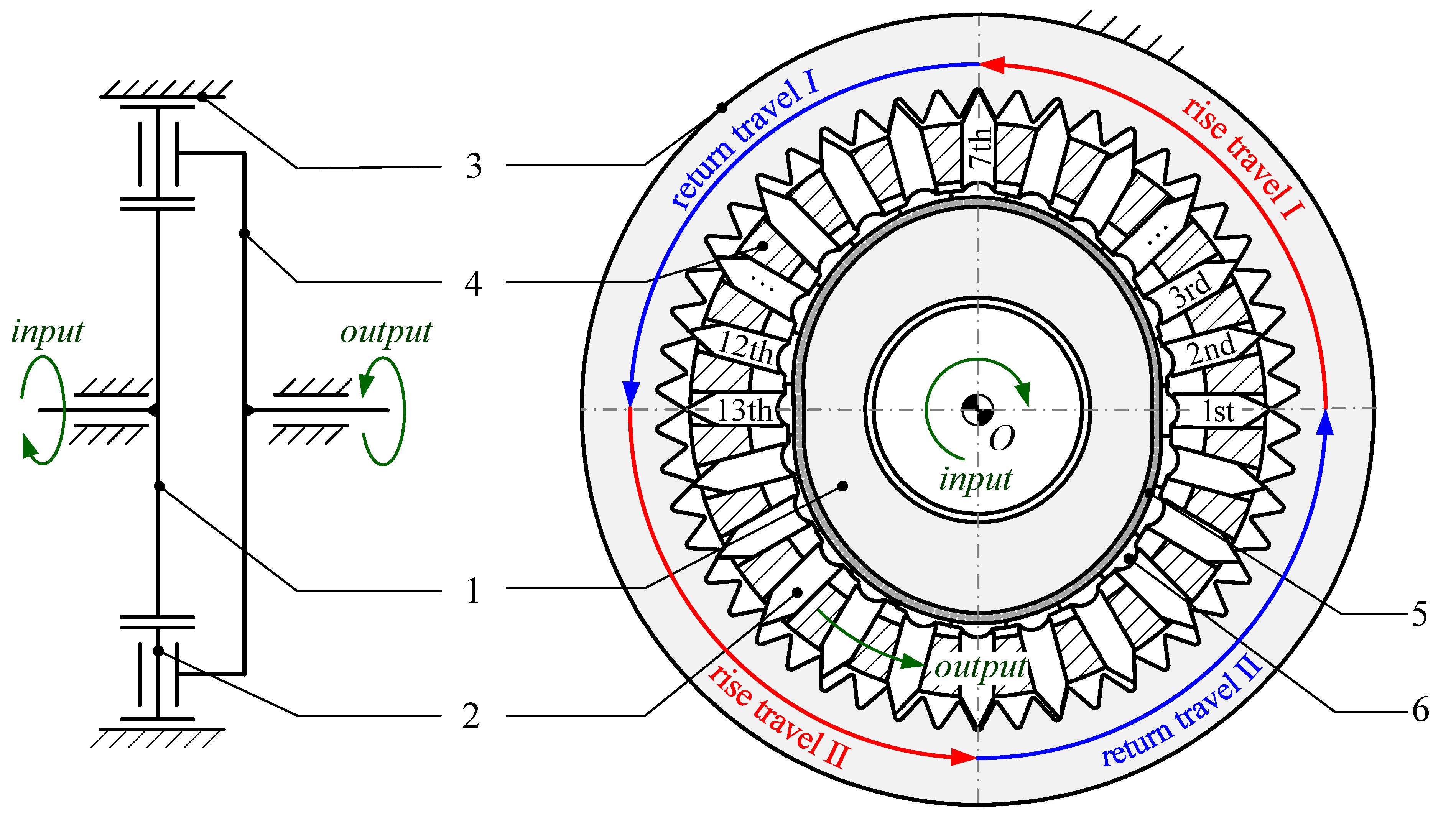
2. Structure and Transmission Principle

The novel movable tooth drive is designed based on the principle of small teeth difference, as the schematic diagram illustrated in Figure 1. The transmission mechanism is mainly comprised of the wave generator 1, tooth carrier 2, ring gear 3, movable tooth 4, needle roller 5, and pivoted segment 6.
The ring gear, wave generator, and tooth carrier are coaxially arranged. The ring gear is fixed with the frame, while the wave generator and tooth carrier are both connected to the frame by revolute pairs, serving as the input and output components, respectively. The movable teeth constitute prismatic pairs with corresponding radial grooves of the tooth carrier, and they, together with the ring gear, compose logarithmic spiral conjugate gear pairs. A pivoted segment is hinged with the bottom of each movable tooth, and the hinge center locates at the lower surface of the pivoted segment. Several needle rollers are distributed between the wave generator surface and the pivoted segments to reduce friction.
As the CAD model of the novel movable tooth drive shows in Figure 2a, similar to the harmonic drive, the teeth are driven by the wave generator to engage with the ring gear, but they are rigid and independent movable teeth rather than an entire gear, i.e., the flexspline of the harmonic drive. Moreover, the force and motion are transferred by these dynamic movable teeth with logarithmic spiral tooth profile, as depicted by the red dotted line in Figure 2b, instead of the balls or rollers utilized in the conventional movable tooth drives.
In particular, since such conjugate tooth profile is almost in surface contact during the engagement, it is characterized with a higher load capacity and stiffness compared with involute or cycloid profiles.
The following describes the transmission principle of the mechanism by taking a meshing period of the movable tooth 1 and the ring gear as an example. The initial position is defined when the movable tooth contacts the tooth tip A of the ring gear, as depicted with the red double dot-dash line in Figure 3a.
When the wave generator rotates clockwise, the movable tooth is actuated to engage with the profile AB of the ring gear, and the tooth carrier is meanwhile driven to rotate counterclockwise owing to the radial groove. The rise travel of the cam is finished until the movable tooth reaches the tooth root B of the ring gear. When the wave generator continues to rotate, the movable tooth returns to initial position A of next meshing period under the guidance of the profile BA, and the return travel of the cam is thereby completed. The simultaneous engaging teeth periodically repeat the above-mentioned motion, i.e., engage-in and engage-out, with phase difference in their rotation angles, therefore accomplishing continuous transmission of the reducer.
Assume that the number of the wave generator lobe, movable teeth, and ring gear teeth are z1, z2, and z3, respectively. The engaging teeth locate in one ring gear tooth profile, and their phase distribution relation is demonstrated in Figure 3b, by taking z1 = 2, z2 = 24, and z3 = 50 as an example. Herein, θh and Δθ refer to the rise travel angle and phase difference, respectively, and they can be expressed as:
θ h = π z 3
Δ θ = 2 π z 1 z 2 z 3

3. Profile Equations

This section examines the meshing theory of the logarithmic spiral conjugate tooth profile, based on the geometric properties of logarithmic spiral, in order to lay a foundation for the subsequent analysis of the force characteristics of such a tooth profile.

3.1. Movable Tooth and Ring Gear

3.1.1. Geometric Properties of Logarithmic Spiral

As is well known, the curve in which polar radius changes exponentially with respect to polar angle is named as a logarithmic spiral, as the red line plotted in Figure 4, and its vector equation is:
r θ = R e θ / tan β e i θ ,   θ , +
where R represents the initial polar radius; β denotes the spiral angle; e denotes the unit vector.
The curve possesses significant properties as follows:
  • Equiangularity: the spiral angle between the tangent line and polar radius is equal at an arbitrary point;
  • Evolute: the curve generated by the curvature center of each point is the identical logarithmic spiral with a phase angle difference π/2;
  • Similarity: the polar radii of any two sectors with the same angle θ are in same proportion eθ/tanβ.

3.1.2. Logarithmic Spiral Conjugate Tooth Profile

For ease of description, vector equations of the wave generator cam profile, the tooth profile of the movable tooth and the ring gear are represented by r1, r2, and r3, respectively, and the subscripts correspond to the serial numbers of the components in Figure 1.
Suppose that the tooth profile of the movable tooth is a known logarithmic spiral and is utilizing the envelope method to calculate the conjugate tooth profile of the ring gear.
As shown in Figure 5, a fixed coordinate system O1-x1y1 is located at the rotation center of the wave generator, and a follow-up coordinate system O2-x2y2 is connected to the movable tooth. In O2-x2y2, the vector equation of the tooth profile of the movable tooth is expressed as:
r 2 O 2 θ = R e θ / tan β cos θ R e θ / tan β sin θ 1 T ,   θ 0
where θ denotes the tooth profile parameter, θ = 0 corresponds to the tooth tip of the movable tooth.
From the analysis in Section 2, if the tooth carrier is fixed and the ring gear is the output component, the wave generator and movable tooth can be regarded as a cam mechanism with the radial translating follower.
Assume that the movable tooth rotates a counterclockwise angle ϕ from the initial position in the light of the logarithmic spiral motion curve, and its radial displacement is formulated as:
s ϕ = R e θ / tan β 1
In O1-x1y1, the vector equation of the tooth profile of the movable tooth is expressed as:
r 2 O 1 θ , ϕ = M O 1 O 2 r 2 O 2 θ
where M O 1 O 2 is the coordinate transformation matrix from O2-x2y2 to O1-x1y1, and expressed as:
M O 1 O 2 = cos ϕ sin ϕ s ϕ cos ϕ sin ϕ cos ϕ s ϕ sin ϕ 0 0 1
The equation of engagement is written as:
f θ , ϕ = n 12 · v = 0
where n12 and v indicate the common normal vector and relative velocity vector at the meshing point. Note that the ring gear is fixed and connected with the frame, so v is the absolute radial velocity of the movable tooth.
By the derivation of Equation (6) with respect to θ and ϕ, respectively, and yields:
n 12 = d r 2 O 1 θ , ϕ d θ e i π 2 v = d r 2 O 1 θ , ϕ d ϕ d ϕ d t
Substituting Equation (9) into Equation (8) results in:
tan β cos θ + tan 2 β + 1 e ϕ / tan β sin θ e θ / tan β tan β tan 2 β sin θ = 0
The solution of Equation (10) is obtained as:
θ = 0 ,   ϕ 0
It can be analyzed from Equation (11) that the tooth profile parameter θ is always equal to 0 corresponding to the arbitrary rotation angle of the movable tooth, indicating that the tooth tip of the movable tooth is always the meshing point, and its motion trajectory just generates the tooth profile of the ring gear.
Substituting Equation (11) into Equation (6), the vector equation of the tooth profile of the ring gear is derived as:
r 3 O 1 ϕ = R e ϕ / tan β cos ϕ R e ϕ / tan β sin ϕ 1 T ,   ϕ 0
Combining Equations (2) and (10), it is found that the tooth profile of the movable tooth and ring gear are two curve segments of the same logarithmic spiral, as shown in Figure 6. Moreover, it is noted that the profile curvature of the movable tooth should be larger than that of the ring gear to avoid interference between them.

3.2. Wave Generator Cam

The wave generator is assumed to be fixed based on the reversal method, and the tooth rotates an angle (θ1 + θ2) counterclockwise from the initial position, as illustrated in Figure 7. Accordingly, during the reverse motion, the profile equation of the wave generator is obtained by the trajectory of the hinge point of the tooth bottom and articulated pivoted segment, which is expressed as:
r 1 = r 0 + s θ 2 e i θ 1 + θ 2
where r0 denotes the pitch circle radius of the wave generator.
Substituting Equation (5) into Equation (13) yields:
r 1 θ = R e θ / I + 1 tan β R + r 0 e i θ , θ 0 , π / z 1
where I represents the speed ratio of the mechanism, and I = (z3z1)/z1.
To analyze the force transmission characteristic of the tooth and wave generator, the meshing angle α is defined as the acute angle between the normal n of the wave generator profile and the radial velocity v of the movable tooth, and it is calculated by:
α = cos 1 n · v n · v

4. Static Model of the Mechanism

It can be known from the analysis in Section 2 that the teeth and ring gear are multi-tooth meshing and over-constrained transmission, and the geometric properties of tooth profile and phase relation of multi-tooth meshing play an important role in the meshing teeth number and load distribution. Hence, it is essential to first research the compatibility condition considering the multi-tooth elastic meshing effect, and then to develop the static model of the mechanism.

4.1. Load Distribution Characteristic of Multi-Tooth Meshing

Assume that the teeth and tooth carrier are temporarily stationary, and a counterclockwise torque M3 is applied to the ring gear, then tiny elastic deformations will occur at the contact points, resulting in a small rotation angle of the tooth carrier considering comprehensive effect of these deformations.
The contact force and elastic deformation between the i-th tooth and ring gear are denoted as N3i and δi, as shown in Figure 8. Herein, the component of the deformation along the circumferential direction is equal to δicosβ because of the equiangularity of logarithmic spiral, and the small rotation angle of the tooth carrier caused is Δτ, thus:
δ i cos β r 3 i = Δ τ
The elastic deformation law of all meshing teeth further satisfies:
δ i cos β r 3 i = δ i + 1 cos β r 3 i + 1 = = Δ τ
where r3i denotes the distance from the contact point to the rotation center O, and according to Equation (12) it is expressed as:
r 3 i = R e θ 2 + i 1 Δ θ / tan β = ρ i sin β
where ρi represents the curvature radius of the ring gear tooth profile at the contact point.
Note that the variation in comprehensive curvature radius of the logarithmic spiral conjugate tooth profile is very little within the whole contact area, so the contact stiffness of the teeth and ring gear is presumed approximately as a constant k, and then the contact force is proportional to the deformation as follows:
N 3 i δ i = N 3 i + 1 δ i + 1 = = k
Equation (19) is the compatibility equation of multi-tooth elastic meshing.
Substituting Equations (17) and (18) into Equation (19) leads to:
N 3 i = k Δ τ tan β ρ i
Equation (20) indicates that the contact force is proportional to the curvature radius of the contact point.
Suppose that the number of meshing teeth in the rise travel is m, and then the total contact force is written as:
i = 1 m N 3 i = i = 1 m k Δ τ cos β R e θ 2 + i 1 Δ θ / tan β = k Δ τ cos β R e θ 2 / tan β i = 1 m e i 1 Δ θ / tan β
The items in Equation (21) successively represent the contact force of each tooth and ring gear, and they change proportionately with respect to the phase difference.
Based on the above analysis, the load distribution factor Ki is further employed to clearly describe the load ratio of each tooth, formulated as:
K i = N 3 i i = 1 m N 3 i
Substituting Equations (20) and (21) into Equation (22) yields:
K i = ρ i i = 1 m ρ i = e i 1 Δ θ / tan β e Δ θ / tan β 1 e m Δ θ / tan β 1
Equation (23) reveals load distribution characteristic of multi-tooth meshing with a logarithmic spiral tooth profile, i.e., the ratio of the curvature radius of each contact point determines the load distribution of the teeth, and they are invariant because teeth always rotate at the same angle θ2 at any instant and the similarity property of the logarithmic spiral. Ki are dimensionless constants depending on the spiral angle β and phase difference Δθ, also not related to the rotation angles of the teeth, and they compose a group of geometric progression matched with the ratio eΔθ/tanβ.

4.2. Static Equilibrium Equations of Components

4.2.1. Ring Gear

The motion characteristic of multi-tooth meshing is demonstrated in Figure 9. It is noticed that the absolute instantaneous center of the tooth during the rise travel corresponds to the curvature center of the ring gear tooth profile, so the centrode just coincides with the evolute. According to geometric relations of the curves, the arm of contact force of each tooth is calculated by:
l i = r 3 i cos β = ρ i sin β cos β
It can be seen that the arm of contact force is proportional to the curvature radius of the contact point as well. Therefore, the direction of contact force, arm of contact force, and radius of contact point form a family of similar right triangles, as depicted with the red solid line in Figure 9.
The torque equilibrium equation of the ring gear is expressed as:
i = 1 m N 3 i l i = M 3 z 1
By substituting Equations (23) and (24) into Equation (25), the contact force is obtained as:
N 3 i = K i i = 1 m N 3 i = e 2 Δ θ / tan β 1 e 2 m Δ θ / tan β 1 e i 1 Δ θ θ 2 / tan β z 1 R cos β M 3

4.2.2. Movable Tooth

Here, assume that the movable tooth is under the dry environment, and the influence of lubrication conditions is ignored. When the i-th tooth rotates a certain angle θ2 from the initial position, its force state during the rise travel is shown in Figure 10, and the equilibrium equation is established as:
F 1 i F 2 i 1 F 2 i 2 F 3 i L i = F k i F r i F c i F k i r 1 i + R r 0 2 ,   i = 1 , 2 , , m
where Li represents the coefficient matrix; F1i and F3i represents the total reaction forces of the wave generator and ring gear to the teeth, respectively; F2 denotes the total reaction forces of the tooth carrier to the teeth; Fki, Fri, and Fci are the inertial forces acting on the centroid Oi, in response to the radial, Coriolis, and tangential accelerations of the teeth, respectively, and they can be ignored considering the small mass of the tooth.
L i = sin α i + φ 1 cos φ 2 cos φ 2 cos β + φ 3 cos α i + φ 1 sin φ 2 sin φ 2 sin β + φ 3 r 1 i sin α i + φ 1 r x cos φ 2 b / 2 sin φ 2 b / 2 sin φ 2 r l cos φ 2 r 3 i cos β + φ 3
r x = r u , i f   r 3 i h r u r x = r 3 i h , i f   r 3 i h < r u
Then the explicit formulas of the forces are derived as:
F 1 i = F 3 i 2 r 3 i r x r l + b tan φ 2 tan φ 2 cos β + φ 3 + r x r l sin β + φ 3 2 r 1 i r x r l + b tan φ 2 tan φ 2 sin α i + φ 1 + r x r l cos α i + φ 1
F 2 i 1 = F 1 i cos α i + φ 1 + φ 2 F 3 i sin β + φ 3 φ 2 2 sin φ 2 cos φ 2
F 2 i 2 = F 1 i cos α i + φ 1 φ 2 F 3 i sin β + φ 3 + φ 2 2 sin φ 2 cos φ 2
where φ1, φ2, and φ3 stand for the friction angles; h and b refer to the full tooth height and width of the tooth; r1i and αi represent the radius and meshing angle at the hinge point, respectively; ru and rl denote the radii of the outer and inner circles of the tooth carrier.

4.2.3. Wave Generator and Tooth Carrier

Suppose that the wave generator rotates clockwise under the input torque M1, and the tooth carrier is driven by the teeth to rotate counterclockwise producing an output torque M2, as illustrated in Figure 11. Their equilibrium equations are expressed as:
i = 1 m F 1 i r 1 i sin α i + φ 1 = M 1 z 1
i = 1 m F 1 i r 1 i cos ϕ i α i φ 1 = F x
i = 1 m F 1 i r 1 i sin ϕ i α i φ 1 = F y
i = 1 m F 2 i 1 r x b 2 tan φ 2 cos φ 2 F 2 i 2 r l b 2 tan φ 2 cos φ 2 = M 2 z 1
i = 1 m F 2 i 1 cos π 2 ϕ i + φ 2 F 2 i 2 cos π 2 ϕ i φ 2 = 0
i = 1 m F 2 i 1 sin π 2 ϕ i + φ 2 F 2 i 2 sin π 2 ϕ i φ 2 = 0
where Fx and Fy are components of force of the frame on the wave generator along x and y directions, respectively; ϕi is the angle between the centerline of the i-th tooth and x-axis, and ϕi = θ2 + 2π(i − 1)/z2.

5. Validation of the Model

In this section, the FEM simulation of contact forces will be implemented on the prototype to verify the effectiveness of the presented model by comparing with the numerical simulation results, and the dimensional and duty parameters are displayed in Table 1 and Table 2, respectively.

5.1. Numerical Simulation

5.1.1. Forces of the Movable Tooth

The variation in forces of the tooth versus the rotation angle during the rise travel is calculated based on Equations (23)–(38) in the cases of one- and two-lobe wave generators, respectively, as illustrated in Figure 12. In the figures, one rise travel is represented by the entire circle in the counterclockwise direction, and the force values are tagged along the direction of polar radius.
Figure 12a,b indicate that forces of the tooth increase exponentially and monotonically versus the rotation angle, thanks to the exponential increase in curvature radius of the ring gear tooth profile. Moreover, it is observed that the variation in the contact force is more stable and smaller in case 2 than that in case 1, as depicted with the blue solid line in the figures, which can be explained by the fact that the ring gear teeth number corresponding to the two-lobe wave generator is twice of that corresponding to the one-lobe wave generator, under the condition of same speed ratio; this results in a smaller rise travel angle and full tooth height of the ring gear tooth profile. In addition, the force of the output side of the groove is larger than that of the other side, and its wear may be more severe.
The variation in total contact force of the teeth in the rise travel versus the rotation angle is shown in Figure 13, by taking case 2 as an example.
It can be seen that the pulsation phenomena, as depicted with the red solid line in the figure, occur periodically at the alternation of the meshing teeth, because the curvature radii of the contact points are different when the teeth enter (point A) and end (point B) the rise travel, resulting in a sudden change in the contact force. Obviously, the pulsation amplitude is related to the spiral angel.
In this case, the variation in contact force of a single tooth is about 10%, and the pulsation amplitude δF of total contact force is approximately 2%, because the sum of curvature radii of all contact points varies very little throughout the rise travel, while the variation in curvature radius of one contact point is relatively lager.

5.1.2. Load Distribution Factor

The load distribution factors of the teeth are calculated by Equation (23), as demonstrated in Figure 14. It is known that the closer the tooth is to the tooth root B of the ring gear, the larger its load ratio is, because of the increasing curvature radius of the ring gear tooth profile. The factors are around 8% in both cases, and their differences in case 2 are less than those in case 1, showing that load distribution of the teeth under the condition of the two-lobe wave generator are relatively even.

5.2. FEM Simulation

The CAD model of the porotype is developed via ABAQUS software by taking the same parameters listed in Table 1 and Table 2.
In the modelling, the grid partition density of the teeth and ring gear are refined to improve calculation accuracy, and the other components are divided automatically, as illustrated in Figure 15a. The numbers of units of the wave generator, teeth, and ring gear are 1309, 20,784, and 39,287, respectively, and the defined unit type is C3D10 (Ten-node quadratic tetrahedron). The material properties are set as follows: the density, Young’s modulus, and Poisson’s ratio are 7800 kg/m3, 206 Gpa, and 0.3, respectively.
In the simulation, a driving torque of 20 Nm is applied to the input shaft, and the contact stresses between the teeth and ring gear during the rise travel are shown in Figure 15b. Then the contact forces are inversely calculated according to Hertz formula, and the simulation results of the analytical model and FEM model are listed in Table 3.
The comparative analysis indicates that the relative error of both results is less than 3%, and the numerical simulation results are all higher than the FEM simulation results. The reason is that the teeth and ring gear are regarded as theoretically line contact and contact force between them is calculated as concentrated force in the analytical model, while a surface contact area around the contact point is actually formed considering deformations in the FEM model, and the contact stresses are apportioned.

6. Discussion

In this section we research the critical conditions of self-locking of the tooth during one meshing period and implement relevant influence factor analysis on force transmission characteristics for discussing the reasonable ranges of the dimensional parameters.

6.1. Self-Locking Analysis

It is noticed that the tooth is a reciprocating moving component, and it will occur self-locking due to the unreasonable parameter design.

6.1.1. Rise Travel

The meshing angle α between the wave generator and the tooth is a significant factor influencing the force transmission, and the self-locking of the tooth will happen during the rise travel if α is too large. The critical meshing angle αc can be obtained by making the denominator of Equation (30) equal to zero:
α c = tan 1 r x r l r x + r l 2 r 1 i b tan φ 2 tan φ 2 φ 1
Note that αc varies with the rotation angle of the tooth, and its minimum is defined as the allowable meshing angle [αc], which is deduced as:
α c = tan 1 R h r l R h + r l 2 r 0 b tan φ 2 tan φ 2 φ 1
Then in this case, the maximum meshing angle αmax should be less than the allowable one, and combining Equation (15) results in a constraint of the dimensional parameters:
α m a x = I + 1 θ h tan 1 I + 1 e θ h / tan β 2 + r 0 / R tan β e θ h / tan β < α c
It can be seen from Equation (41) that R, r0, and β are the main dimensional parameters influencing αmax. To make the research more universal, set r0/R as the pitch circle radius coefficient, and it is also applicable to the following discussions below. For the cases in Section 5, based on Equations (40) and (41), the allowable and maximum meshing angles are 73.6° and 7.0°, respectively.

6.1.2. Return Travel

The tooth, pushed by the tooth carrier during the return travel, returns to the initial position of next meshing period under the guide of the ring gear tooth profile, and its force state is illustrated in Figure 16, then the equilibrium equation is established as:
F 1 i F 2 i 1 F 2 i 2 F 3 i L i = 0 0 0 ,   i = 1 , 2 , , m
L i = sin φ 1 α i cos φ 2 cos φ 2 cos β φ 3 cos φ 1 α i sin φ 2 sin φ 2 sin β + φ 3 r 1 i sin φ 1 α i r l cos φ 2 + b / 2 sin φ 2 b / 2 sin φ 2 r x cos φ 2 r 3 i cos β φ 3
The forces are thus derived as:
F 3 i = F 1 i r x + r l + b tan φ 2 2 r 1 i tan φ 2 sin φ 1 α i + r x r l cos φ 1 α i r x + r l + b tan φ 2 2 r 3 i tan φ 2 cos β φ 3 + r x r l sin β φ 3
F 2 i 1 = F 1 i cos φ 1 α i + φ 2 + F 3 i sin β φ 3 φ 2 2 sin φ 2 cos φ 2
F 2 i 2 = F 1 i cos φ 1 α i φ 2 + F 3 i sin β φ 3 + φ 2 2 sin φ 2 cos φ 2
Similarly, let the denominator of Equation (44) to be greater than zero yields the other constraints of the dimensional parameters:
β > φ 3
r u R tan φ 2 + tan β φ 3 + r l R tan φ 2 tan β φ 3 2 e θ h / tan β tan φ 2 > 0
Equation (48) indicates that the radii of the outer and inner circles of the tooth carrier, ru and rl, should satisfy the specific boundary condition to avoid self-locking of the tooth during the return travel, which is notable in the dimensional synthesis. In other words, the reset springs may need to be installed to help the tooth complete the return motion.

6.2. Force Transmission Characteristics

On the premise that the teeth do not self-lock, the pulsation amplitude of total contact force and the force transmission rate are investigated to improve the force performance of the tooth.

6.2.1. Pulsation Amplitude of Total Contact Force

As analyzed in Section 5.1, the total contact force occurs as periodical pulsation due to the alternation of the meshing teeth, and its amplitude δF is expressed as follows through Equation (21):
δ F = 1 i = 1 m N 3 i | θ 2 = 0 i = 1 m N 3 i | θ 2 = Δ θ = 1 1 e Δ θ / tan β
The variation in δF versus β and I is illustrated in Figure 17a based on Equation (49). It can be observed that δF decreases with the increases in β and I, because the change in curvature radius of the ring gear tooth profile becomes smaller. Additionally, β is preferably more than 10° to ensure δF less than 10% for stable force of the conjugate tooth profile.

6.2.2. Force Transmission Rate

To evaluate force transmission rate between one tooth and ring gear from the input to the output, the non-dimensional index ηF is introduced throughout the rise travel, and it is formulated according to Equations (30)–(32) with frictions ignored as follows:
η F = 0 θ h F 2 1 F 2 2 F 1 d θ 2 θ h = 0 θ h cos α + β sin β d θ 2 θ h
The variation in ηF versus r0/R and β is illustrated in Figure 17b. It shows that ηF increases with the decrease in β, because of the increases in the meshing angle α and effective output resultant force. In addition, ηF increases with the increase in r0/R when β < 30°, otherwise it is almost unaffected.

6.3. Selection of Dimensional Parameters

Based on the above analysis, the feasible ranges of the dimensional parameters are further discussed.

6.3.1. Pitch Circle Radius Coefficient r0/R and Spiral Angle β

The contour maps of αmax, ηF, and δF versus r0/R and β are plotted in Figure 18 with comprehensive consideration of Equations (41), (47), (49), and (50). Here, black solid and dotted lines represent different force transmission rates and maximum meshing angles, and red dotted lines denote the pulsation amplitude.
As can be seen from the figure, the ranges of r0/R and β are narrowed when ηF increases and αmax decreases for meeting the requirement of higher force transmission rate of the tooth and better force performance of the wave generator. Moreover, by comparing Figure 18a with Figure 18b, the selectable ranges also become narrow as I decreases at the same condition. It is worth noting that the consideration of δF can further help the selection of β.

6.3.2. Radius Coefficients of the Outer and Inner Circles of the Tooth Carrier, ru/R and rl/R

After the determination of r0/R and β, the design of ru/R and rl/R is not only related to self-locking avoidance, but also to the kinematic interference. Specifically, ru/R must be less than 1, and rl/R ought to be more than the maximum lift of the wave generator to reserve allowance for the pivoted segment. Therefore, the structural constraints are expressed as:
r 0 R + e θ h / tan β 1 < r l R < r u R < 1
According to Equations (48) and (51), the variation in rl/R versus r0/R and β is demonstrated in Figure 19. Herein, red solid lines, as the lower bounds, correspond to contour curves of different values of rl/R; black solid lines, as the upper bounds, are plotted through Equation (48).
It can be seen from the figure that the range of rl/R becomes wider with the increase in β, owing to the decreases in the maximum lift of the wave generator. In addition, by comparing Figure 19a with Figure 19b, the range of rl/R is narrowed while I decreases. For example, referring to Figure 19a, if r0/R and β are given as 0.54 and 30°, the optional range of rl/R is about 0.65~0.9 under the condition of I = 24.

7. Conclusions

This paper presents a static model of the novel transmission mechanism with logarithmic spiral tooth profile, to analyze force characteristic of the conjugate tooth profile with consideration of the multi-tooth elastic meshing effect. The conclusions are drawn as follows:
(1)
The tooth profiles of movable tooth and ring gear can be designed by two pieces of curves taken from the same one logarithmic spiral. They are almost in full surface contact under the working condition because their curvatures are very close, different from the conventional involute or cycloidal tooth profiles creating a linear contact. Thus, the novel drive can bear more loads and has higher rigidity than the conventional ones, which can be applied in the fields with heavy load requirements, such as machine tools, petroleum drilling platforms, industrial robots, etc.;
(2)
The contact force between one tooth and ring gear is proportional to the curvature radius of the contact point, which increases exponentially and monotonically corresponding to the curvature radius of the logarithmic spiral tooth profile during the rise travel, and the load distribution of the teeth is determined according to the ratio of the curvature radius of their contact points;
(3)
The pulsations of total contact force appear periodically at the alternation of the teeth in the multi-tooth meshing condition, because the closer the tooth is to the tooth root of the ring gear, the larger its load ratio is, and the pulsation amplitude is related to the spiral angle, rise travel angle, and ring gear tooth number;
(4)
There may be self-locking between the tooth and ring gear in a meshing period because of the unreasonable parameter design, especially during the return travel; therefore it is recommended to select feasible ranges of the dimensional parameters, or equip the reset springs, to avoid the self-locking, and the comprehensive consideration of the pulsation amplitude and force transmission rate can further help the dimensional synthesis.
This paper only researches static modelling of the transmission mechanism under ideal conditions, and mechanical characteristic analysis considering elastic surface contact, lubrication conditions and manufacturing errors need to be further studied. Moreover, it is noticed that there is a singular point at the midpoint of a meshing period, and relevant modification research will be reported later.

Author Contributions

Conceptualization, Y.Y.; methodology, Y.Y. and G.Z.; software, G.Z.; validation, G.Z.; formal analysis, G.Z.; investigation, Y.Y. and G.Z.; resources, Y.Y.; data curation, G.Z.; writing—original draft preparation, G.Z.; writing—review and editing, G.Z.; visualization, G.Z.; supervision, Y.Y.; project administration, Y.Y.; funding acquisition, Y.Y. All authors have read and agreed to the published version of the manuscript.

Funding

This research was funded by the National Natural Science Foundation of China, grant number 52075363.

Institutional Review Board Statement

Not applicable.

Informed Consent Statement

Not applicable.

Data Availability Statement

Not applicable.

Conflicts of Interest

The authors declare no conflict of interest.

Nomenclature

z1, z2, and z3the number of the wave generator lobe, movable teeth, and ring gear teeth
θhthe rise travel angle
Δθthe phase difference
Rthe initial polar radius
βthe spiral angle
ethe unit vector
r1, r2, and r3the vector equations of wave generator cam profile, the tooth profile of movable tooth and ring gear
O1-x1y1the fixed coordinate system located at the rotation center of the wave generator
O2-x2y2the follow-up coordinate system connected to the movable tooth.
θthe tooth profile parameter
ϕthe rotation angle of movable tooth
sthe radial displacement of movable tooth
M O 1 O 2 the coordinate transformation matrix from O2-x2y2 to O1-x1y1
n12 and vthe common normal vector and relative velocity vector at the meshing point
r0the pitch circle radius of the wave generator
nthe normal wave generator profile
αthe acute angle between n and v
Ithe speed ratio of the mechanism
M3the torque applied to the ring gear
N3i and δithe contact force and elastic deformation between the i-th tooth and ring gear
Δτthe small rotation angle of the tooth carrier
r3ithe distance from the contact point to the rotation center O
ρithe curvature radius of the ring gear tooth profile at the contact point
kthe contact stiffness of the teeth and ring gear
Kithe load distribution factor
lithe arm of contact force
Lithe coefficient matrix
F1i and F3ithe total reaction forces of the wave generator and ring gear to the teeth
F2the total reaction forces of the tooth carrier to the teeth
Fki, Fri, and Fcithe inertial forces acting on the centroid
φ1, φ2, and φ3the friction angles
h and bthe full tooth height and width of the tooth
r1i and αithe radius and meshing angle at the hinge point
ru and rlthe radii of the outer and inner circles of the tooth carrier
M1 and M2the input torque and output torque
Fx and Fythe components of force of the frame on the wave generator along x and y directions
ϕithe angle between the centerline of the i-th tooth and x-axis
δFthe pulsation amplitude of total contact force
αcthe critical meshing angle
c]the allowable meshing angle
αmaxthe maximum meshing angle
r0/Rthe pitch circle radius coefficient
ηFthe force transmission rate
ru/R and rl/Rthe radius coefficients of the outer and inner circles of the tooth carrier

References

  1. Pham, A.D.; Ahn, H.J. High precision reducers for industrial robots driving 4th industrial revolution: State of arts, analysis, design, performance evaluation and perspective. Int. J. Precis. Eng. Manufact.-Green Technol. 2018, 5, 519–533. [Google Scholar] [CrossRef]
  2. Kudrijavcev, V.N. Planetary Gear Train; Mechanical Engineering: Leningrad, Russian, 1966. [Google Scholar]
  3. Malhotra, S.K.; Parameswaran, M.A. Analysis of a cycloid speed reducer. Mech. Mach. Theory 1983, 18, 491–499. [Google Scholar] [CrossRef]
  4. Xuan, L.; Xie, C.; Guan, T.M.; Lei, L.; Jiang, H. Research on dynamic modeling and simulation verification of a new type of FT pin-cycloid transmission. Proc. Inst. Mech. Eng. Part C J. Mech. Eng. Sci. 2019, 233, 6276–6288. [Google Scholar] [CrossRef]
  5. Gorla, C.; Davoli, P.; Rosa, F.; Longoni, C.; Chiozzi, F.; Samarani, A. Theoretical and experimental analysis of a cycloidal speed reducer. ASME J. Mech. Des. 2008, 130, 112604. [Google Scholar] [CrossRef]
  6. Li, X.; Li, C.Y.; Wang, Y.W.; Chen, B.K.; Lim, T.C. Analysis of a cycloid speed reducer considering tooth profile modification and clearance-fit output mechanism. ASME J. Mech. Des. 2017, 139, 033303. [Google Scholar] [CrossRef]
  7. Hidaka, T.; Wang, H.Y.; Ishida, T. Rotational transmission error of K-H-V planetary gears with cycloid gear (1st Report, Analytical method of the rotational transmission error). Trans. Jpn. Soc. Mech. Eng. Ser. C 1994, 60, 645–653. [Google Scholar] [CrossRef]
  8. Meng, Y.H.; Wu, C.L.; Ling, L.P. Mathematical modelling of the transmission performance of 2K-H pin cycloid planetary mechanism. Mech. Mach. Theory 2007, 42, 776–790. [Google Scholar] [CrossRef]
  9. Hsieh, C.F. Dynamics analysis of cycloidal speed reducers with pinwheel and nonpinwheel designs. ASME J. Mech. Des. 2014, 136, 091008. [Google Scholar] [CrossRef]
  10. Hsieh, C.F. Traditional versus improved designs for cycloidal speed reducers with a small tooth difference: The effect on dynamics. Mech. Mach. Theory 2015, 86, 15–35. [Google Scholar] [CrossRef]
  11. Kumar, N.; Kosse, V.; Oloyede, A. A new method to estimate effective elastic torsional compliance of single-stage cycloidal drives. Mech. Mach. Theory 2016, 105, 185–198. [Google Scholar] [CrossRef]
  12. Xu, L.X. A dynamic model to predict the number of pins to transmit load in a cycloidal reducer with assembling clearance. Proc. Inst. Mech. Eng. Part C J. Mech. Eng. Sci. 2019, 233, 4247–4269. [Google Scholar] [CrossRef]
  13. Xu, L.X.; Chen, B.K.; Li, C.Y. Dynamic modelling and contact analysis of bearing-cycloid-pinwheel transmission mechanisms used in joint rotate vector reducers. Mech. Mach. Theory 2019, 137, 432–458. [Google Scholar] [CrossRef]
  14. Kim, K.H.; Lee, C.S.; Ahn, H.J. Torsional rigidity of a cycloid drive considering finite bearing and hertz contact stiffness. In Proceedings of the ASME International Design Engineering Technical Conferences/Computers and Information in Engineering Conference, San Diego, CA, USA, 30 August–2 September 2009. [Google Scholar]
  15. Li, S.T. Design and strength analysis methods of the trochoidal gear reducers. Mech. Mach. Theory 2014, 81, 140–154. [Google Scholar] [CrossRef]
  16. Blagojevic, M.; Marjanovic, N.; Djordjevic, Z.; Stojanovic, B.; Disic, A. A new design of a two-stage cycloidal speed reducer. ASME J. Mech. Des. 2011, 133, 085001. [Google Scholar] [CrossRef]
  17. Xu, L.X.; Yang, Y.H. Dynamic modelling and contact analysis of a cycloid-pin gear mechanism with a turning arm cylindrical roller bearing. Mech. Mach. Theory 2016, 104, 327–349. [Google Scholar] [CrossRef]
  18. Dong, H.M.; Wang, D.L.; Ting, K.L. Kinematic effect of the compliant cup in harmonic drives. ASME J. Mech. Des. 2011, 133, 051004. [Google Scholar] [CrossRef]
  19. Kayabasi, O.; Erzincanli, F. Shape optimization of tooth profile of a flexspline for a harmonic drive by finite element modelling. Mater. Des. 2007, 28, 441–447. [Google Scholar] [CrossRef]
  20. Li, X.Z.; Song, C.S.; Yang, Y.; Zhu, C.C.; Liao, D.L. Optimal design of wave generator profile for harmonic gear drive using support function. Mech. Mach. Theory 2020, 152, 103941. [Google Scholar] [CrossRef]
  21. Zhu, C.Z.; Wang, X.J.; Li, Z.L.; Jun, L.; Zheng, J.Q. Research on static and dynamics mechanical characteristics of flexible bearing in harmonic reducer. Int. J. Adv. Robot. Syst. 2020, 17, 1729881420919953. [Google Scholar]
  22. Pacana, J. The impact of the structural form on the stress distribution in a flexspline of a hermetic harmonic drive. J. Theor. Appl. Mech. 2020, 58, 1049–1060. [Google Scholar] [CrossRef]
  23. Tjahjowidodo, T.; Al-Bender, F.; Van Brussel, H. Theoretical modelling and experimental identification of nonlinear torsional behaviour in harmonic drives. Mechatronics 2013, 23, 497–504. [Google Scholar] [CrossRef]
  24. Ma, D.H.; Wu, J.N.; Liu, T.; Yan, S.Z. Deformation analysis of the flexspline of harmonic drive gears considering the driving speed effect using laser sensors. Sci. China. Technol. Sci. 2017, 60, 1175–1187. [Google Scholar] [CrossRef]
  25. Ma, J.F.; Li, C.; Luo, Y.C.; Cui, L.L. Simulation of meshing characteristics of harmonic reducer and experimental verification. Adv. Mech. Eng. 2018, 10, 1–9. [Google Scholar] [CrossRef]
  26. Chen, X.X.; Liu, Y.S.; Xing, J.Z.; Lin, S.Z.; Ma, M. A novel method based on mechanical analysis for the stretch of the neutral line of the flexspline cup of a harmonic drive. Mech. Mach. Theory 2014, 76, 1–19. [Google Scholar] [CrossRef]
  27. Xiong, Y.; Zhu, Y.S.; Yan, K. Load analysis of flexible ball bearing in a harmonic reducer. ASME J. Mech. Des. 2020, 142, 022302. [Google Scholar] [CrossRef]
  28. Mahanto, B.S.; Sahoo, V.; Maiti, R. Effect of cam insertion on stresses in harmonic drive in industrial robotic joints. Procedia Comput Sci. 2018, 133, 432–439. [Google Scholar] [CrossRef]
  29. Yague-Spaude, E.; Gonzalez-Perez, I.; Fuentes-Aznar, A. Stress analysis of strain wave gear drives with four different geometries of wave generator. Meccanica 2020, 55, 2285–2304. [Google Scholar] [CrossRef]
  30. Xu, L.Z.; Liang, Y.L. Output torque for electromagnetic harmonic drive. Adv. Mech. Eng. 2015, 7, 721543. [Google Scholar] [CrossRef]
  31. Xu, L.Z.; Liang, Y.L. Torque for an electromagnetic harmonic movable tooth drive system. Mech. Mach. Theory 2016, 98, 190–198. [Google Scholar] [CrossRef]
  32. Zhou, G.C.; Yang, Y.H.; Xie, R.; Tao, S.Y. A design method for a novel movable tooth drive with logarithmic spiral conjugated tooth profiles. Proc. Inst. Mech. Eng. Part C J. Mech. Eng. Sci. 2022, 236, 9527–9542. [Google Scholar] [CrossRef]
Figure 1. Schematic diagram of the novel movable tooth drive. 1-wave generator; 2-tooth carrier; 3-ring gear; 4-movable tooth; 5-needle roller; 6-pivoted segment.
Machines 10 00837 g001
Figure 2. CAD model. (a) virtual prototype; (b) movable teeth and pivoted segments.
Machines 10 00837 g002
Figure 3. Transmission principle. (a) a meshing period of conjugate tooth profile; (b) multi-tooth meshing phase relation.
Machines 10 00837 g003
Figure 4. Logarithmic spiral. (a) equiangularity; (b) evolute; (c) similarity.
Machines 10 00837 g004
Figure 5. Envelope motion of the movable tooth.
Machines 10 00837 g005
Figure 6. Logarithmic spiral conjugate tooth profiles.
Machines 10 00837 g006
Figure 7. Wave generator profile model.
Machines 10 00837 g007
Figure 8. Force and elastic deformation at the contact point.
Machines 10 00837 g008
Figure 9. Arm of contact force of each tooth.
Machines 10 00837 g009
Figure 10. Force state of the i-th tooth during the rise travel.
Machines 10 00837 g010
Figure 11. Force state of the components during the rise travel. (a) Wave generator; (b) Tooth carrier.
Machines 10 00837 g011
Figure 12. Variation in forces of the tooth versus the rotation angle. (a) Case 1; (b) Case 2.
Machines 10 00837 g012
Figure 13. Variation in total contact force versus the rotation angle.
Machines 10 00837 g013
Figure 14. Load distribution factor.
Machines 10 00837 g014
Figure 15. FEM simulation of the prototype with the two−lobe wave generator. (a) Grid partition; (b) Contact stresses of the teeth and ring gear.
Machines 10 00837 g015
Figure 16. Force state of the i-th tooth during the return travel.
Machines 10 00837 g016
Figure 17. Influence of the dimensional parameters. (a) Variation in δF versus β and I; (b) Variation in ηF versus r0/R and β.
Machines 10 00837 g017
Figure 18. Range of r0/R and β corresponding to different αmax, ηF, and δF. (a) I = 24; (b) I = 20.
Machines 10 00837 g018
Figure 19. Ranges of ru/R and rl/R corresponding to different r0/R and β. (a) I = 24; (b) I = 24.
Machines 10 00837 g019
Table 1. Dimensional parameters of the prototype.
Dimensional ParameterValue
Initial polar radius R (mm)65
Pitch circle radius of the wave generator r0 (mm)35
Radius of the outer circle of the tooth carrier ru (mm)63
Radius of the inner circle of the tooth carrier rl (mm)47
Spiral angle β (°)30
Width of the tooth b (mm)6
Table 2. Duty parameters of the prototype.
Duty ParametersCase 1Case 2
Number of wave generator lobe z112
Number of the teeth z22424
Number of ring gear teeth z32550
Sequence of the teeth in the rise travel1st~12th1st~6th, 13th~18th
Speed ratio I24
Input torque M120 Nm
φ1 = arctan0.05, φ2 = φ3 = arctan0.1.
Table 3. Comparison of contact forces between the analytical model and the FEM model.
Rotation Angle θ21/6θh1/3θh1/2θh2/3θh5/6θhθh
Analytical model (N)278.1283.2288.4293.7299.1304.5
FEM model (N)272.2276.8281.1286.0291.2295.9
Relative error2.2%2.3%2.6%2.7%2.7%2.9%
Publisher’s Note: MDPI stays neutral with regard to jurisdictional claims in published maps and institutional affiliations.

