Article

Effects of Currents on Human Freestyle and Breaststroke Swimming Analyzed by a Rigid-Body Dynamic Model

1
Institute of AI and Robotics, Fudan University, Shanghai 200433, China
2
MOE Engineering Research Center of AI & Robotics, Fudan University, Shanghai 200433, China
3
Shanghai Engineering Research Center of AI & Robotics, Fudan University, Shanghai 200433, China
*
Author to whom correspondence should be addressed.
Machines 2022, 10(1), 17; https://doi.org/10.3390/machines10010017
Submission received: 8 November 2021 / Revised: 16 December 2021 / Accepted: 21 December 2021 / Published: 24 December 2021
(This article belongs to the Special Issue Feature Papers to Celebrate the First Impact Factor of Machines)

Abstract

:
Swimming is a kind of complex locomotion that involves the interaction between the human body and the water. Here, to examine the effects of currents on the performance of freestyle and breaststroke swimming, a multi-body Newton-Euler dynamic model of human swimming is developed. The model consists of 18 rigid segments, whose shapes and geometries are determined based on the measured data from 3D scanning, and the fluid drags in consideration of the current are modeled. By establishing the interrelations between the fluid moments and the swimming kinematics, the underlying mechanism that triggers the turning of the human body is uncovered. Through systematic parametric analyses, the effects of currents on swimming performance (including the human body orientation, swimming direction, swimming speed, and propulsive efficiency) are elucidated. It reveals that the current would turn the human body counterclockwise in freestyle swimming, while clockwise in breaststroke swimming (which means that from the top view, the human trunk, i.e., the vector pointing from the bottom of feet to the top of the head, rotates counterclockwise or clockwise). Moreover, for both strokes, there exists a critical current condition, beyond which, the absolute swimming direction will be reversed. This work provides a wealth of fundamental insights into the swimming dynamics in the presence of currents, and the proposed modeling and analysis framework is promising to be used for analyzing the human swimming behavior in open water.

Graphical Abstract

1. Introduction

Swimming sport, one of the most challenging locomotion techniques for humans, is generally achieved through coordinated movements of the limbs and the trunk. Evaluation of swimming performance is generally multifactorial, and it has been widely acknowledged that the dynamic interaction between the human body and the water plays a key role [1,2,3]. Understanding their mutual effects is of great value in different fields, including performance enhancement in competitive swimming [4,5], effect improvement in rehabilitation training [6], and design optimization of underwater exoskeletons [7]. Research on human swimming dynamics started from the end of the last century, and currently, the mainstream methods are computational fluid dynamics (CFD) [8,9,10,11,12,13,14,15,16,17], experiments [18,19,20,21,22,23,24,25], and multi-rigid body dynamics [26,27,28,29,30].
CFD has developed rapidly in recent decades, and previous research on human swimming dynamics was mainly carried out via CFD simulations. Bixler is one of the pioneers to apply CFD to the analysis of human swimming [8]. By simplifying the palm of a human hand into a disk and based on two-dimensional (2D) CFD simulations, the fluid force applied to the palm can be obtained. On this basis, three-dimensional (3D) CFD was further developed to analyze the fluid force applied to the arm at different attack angles [9] and the passive drag [13] during swimming. CFD techniques were also used to analyze the effects of the body shape on pressure drag, friction drag, and wave-making resistance [10]. Note that rather than examining the whole human body during swimming, the abovementioned studies mainly focus on the force conditions of certain body parts or on the scenarios in which the human body glides in a fixed posture. This is because, during swimming, the joint motions are complex, and the deformations of the human body are non-negligible, which makes it challenging to establish a dynamic human body mesh model. Hence, it becomes quite difficult to employ CFD simulations to analyze the swimming dynamics of the whole human body. One way to partly solve the abovementioned issue is to adopt a meshless model, i.e., the smooth particle hydrodynamic (SPH) method. Cohen et al. [12,15] have performed inspiring research in this area by integrating the SPH method with biomechanical models to tackle problems such as optimizing dolphin kick [4,16], calculating lift and resistance on hands during freestyle swimming [17], and understanding the effects of asymmetrical stokes [11].
Experiment is also an effective means to analyze the actual swimming process and to verify the CFD results. Based on different sensors (including inertial measurement units, force sensors, underwater cameras, and motion capture systems) and specially-designed mechanical device systems, kinematic data of the joints and the fluid forces applied on a part of the human body during swimming can be obtained, and the energy consumption can be calculated. For example, a mechanical system consisting of pulleys, chains, and force sensors was developed to measure the fluid force applied on the human hand under unsteady currents conditions [21]. There are also many studies using the particle image velocimetry (PIV), an optical-based technology, to measure the actual flow fields around swimmers [23,24,25]. Compared with conventional experiment methods, PIV has obvious merits: it does not require additional sensors to be attached to the subjects so that the swimming motion will not be disrupted; it can easily measure the instantaneous velocity, vorticity, and heat-flux rates of the whole flow field, which are difficult to be achieved via traditional means. Despite the advantages, the high equipment demand, the time-consuming flow field calibration, and the limited observation area greatly impede the application of PIV.
Overall, experiments are very helpful in understanding post-performance swimming phenomena, while they are powerless in predicting swimming performance or swimming dynamics in unknown situations. CFD simulations, on the other hand, are effective in examining the effects of variable conditions; however, they hold an inherent defect in that they generally call for huge computation time and memory space, which makes them difficult to be used for large-scale parameter analysis and optimization. Therefore, the CFD simulation is not a suitable tool for acquiring systematic understanding or predictions of human swimming dynamics either.
One way to tackle the above issues is to develop models and to perform analysis based on multibody system dynamics, as relevant research is scarce [26,27,28]. The most representative work comes from Nakashima et al. [30]; they established a multi-rigid-body dynamic model of human swimming based on Newton-Euler equations. Inertial forces, unsteady drag forces, and buoyancy are included in the model. On this basis, a simulation software named “SWUM” was developed, which has been utilized to analyze the dynamics of freestyle, breaststroke, backstroke, and butterfly-stroke based on kinematic signals [31]. SWUM has also manifested its value in underwater walking rehabilitation [6,32], multi-objective optimization of underwater motions (e.g., swimming with flippers, water polo, kayaking, synchronized swimming, etc.) [33,34,35] and swimming stroke-path optimization for swimmers with hemiplegia or unilateral radial artery deficiency [36,37]. It is worth noting that SWUM has several limitations: it requires pre-measured kinematic signals of the joint motions, it does not consider the mutual interaction of limbs, and the accuracy of the fluid forces is lower than that of CFD simulations. However, due to its extremely high calculation efficiency, SWUM receives wide applications, especially in understanding the qualitative characteristics of different swimming strokes, interpretation of swimming dynamics, and motion optimization.
In the abovementioned studies, the major focuses are on indoor competitive swimming. Since the currents are relatively weak in the pool environment, the effects of currents on swimming are generally negligible. Nevertheless, for military personnel, rescue personnel, and triathletes, swimming in open water environments is common. The presence of currents, tides, and waves will significantly affect the human swimming performance [38]. One characteristic research comes from Beaumont et al. [39], who carried out preliminary investigation on open-water swimming through CFD simulations, with particular attention to the fluid resistances applied to the swimmer at different positions in the presence of currents. By evaluating the velocity and pressure fields, the best position for a draft swimmer relative to the lead swimmer is also determined. Except for this work, research regarding the effects of currents on human swimming is sorely lacking. However, understanding how the currents influence the human swimming performance has important implications. On one hand, examining the current effects is helpful for athletes to improve their competitive ability in open-water swimming and for marines to better perform underwater missions; on the other hand, taking the currents into account is important and necessary for designing swimming auxiliary equipment and underwater robotic exoskeletons.
Considering the obvious drawbacks of CFD simulations and experimental methods (i.e., the former requires huge computation time, and the latter are powerless in predicting the swimming dynamics in unknown scenarios), this paper examines the effects of currents based on a multi-rigid-body dynamic model of human swimming. Such a model, due to its high computational efficiency and acceptable accuracy, would be appropriate for a systematic parametric study. Given the popularity and effectiveness of the swimming strokes, this research particularly focuses on breaststroke and freestyle swimming.
Specifically, to provide evidence for modeling, the geometric parameters of the human body are firstly measured through 3D scanning. Inherited the modeling procedures from Nakashima et al. [30], an analytical model of the human body consisting of 18 rigid segments is developed, in which the geometric shapes of the segments are optimized according to the measured data. Aiming at such a complicated multi-rigid-body system, Newton-Euler equations are established to describe the combined translational and rotational dynamics of the human body. Benefiting from the low computation cost of the model, both case studies and systematic parameter analyses are carried out to understand the effects of currents on breaststroke and freestyle swimming. By associating the fluid moment with the swimming kinematics, the underlying mechanism for triggering the turning is elucidated. Moreover, parameter analyses successfully uncover the quantitative dependence of swimming performance on current direction and current velocity.

2. Dynamic model of Human Swimming

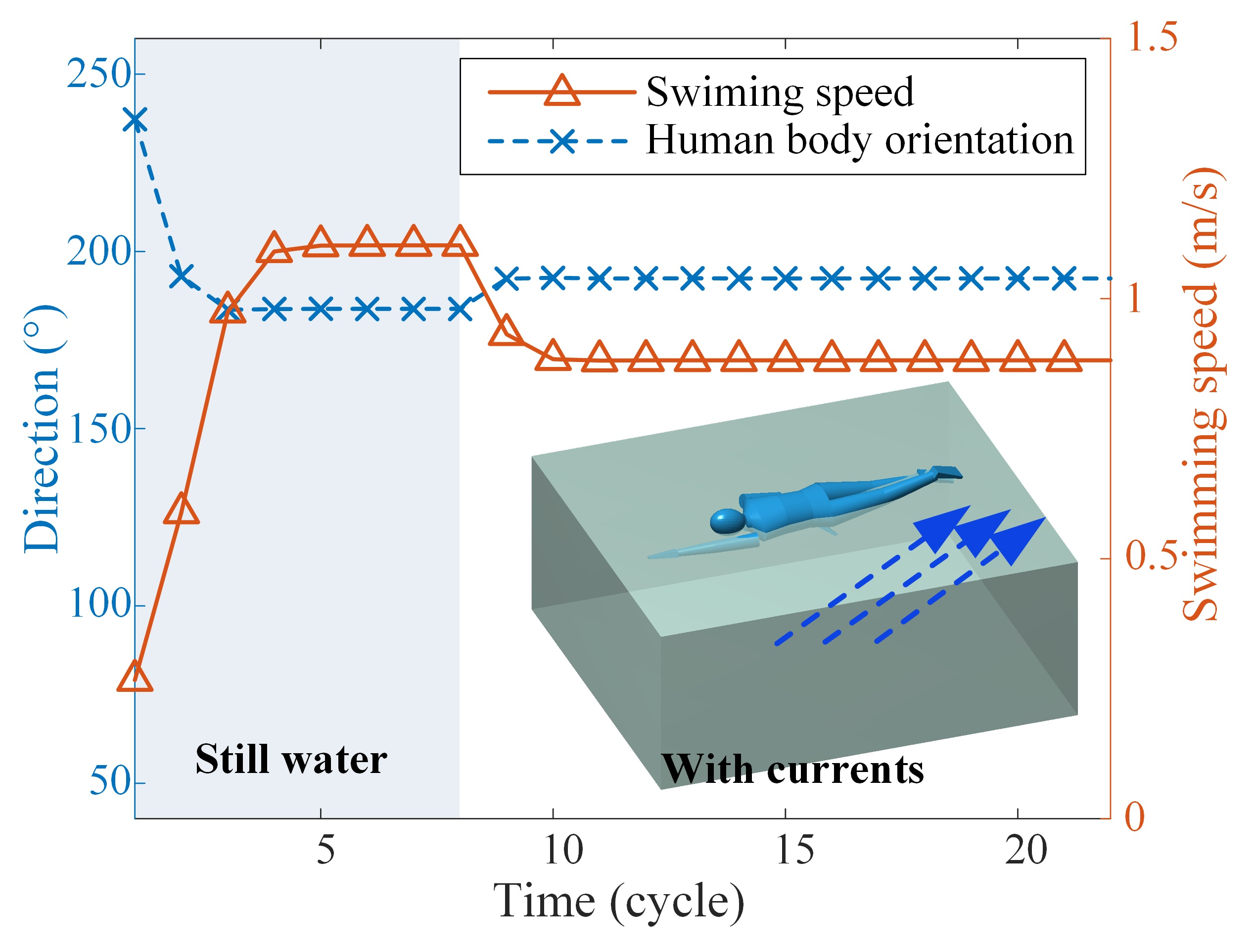
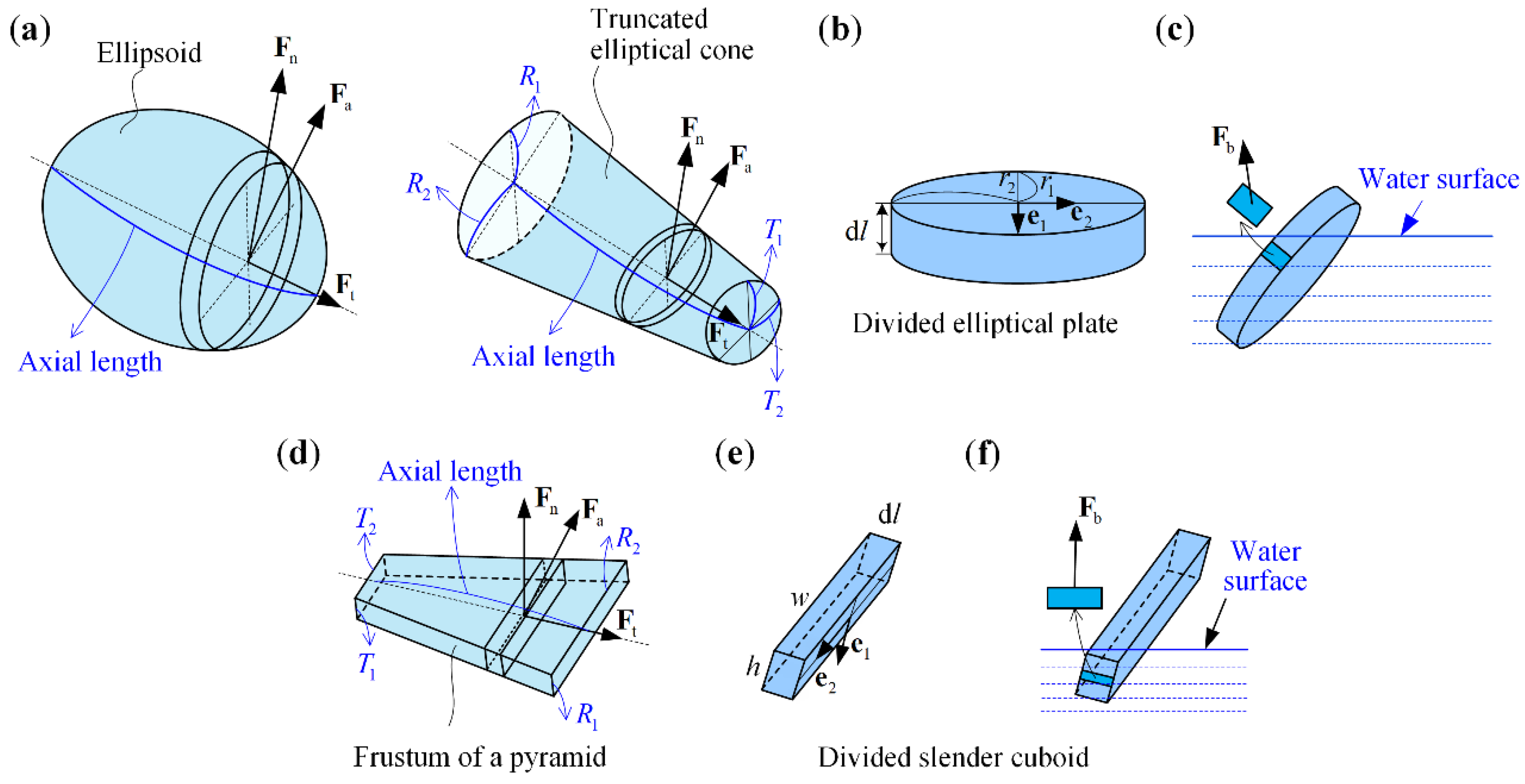
2.1. Geometric Modeling of the Human Body

To accurately determine the geometry parameters of the human body, 3D scanning based on a multi-functional handheld 3D scanner (EinScan® Pro 2X Plus) is performed in this research. In this scanning test, an adult male college student (age 26 years old, height 1.71 m, weight 65.0 kg) was selected as the subject. The protocol was approved by the university ethics committee. The subject was fully informed of the aims and details of the protocol and voluntarily agreed to participate, with the signing of written informed consent.
Based on the point cloud data obtained via 3D scanning, Figure 1a shows the generated 3D CAD model of the subject, which indicates that the human-body surface is of complex shape. To facilitate the subsequent dynamic modeling process, simplification of the human-body geometric model is executed. According to the basis for human-body segmentation (Table 1, [40]), the human-body model (Figure 1a) is simplified into a multi-rigid-body geometric model consisting of 18 rigid segments (Figure 1b), namely, the head, neck, shoulder, upper trunk, middle trunk, lower trunk, thigh, shank, foot, upper arm, forearm, and hand segments. In this study, rather than representing all segments as truncated elliptical cones [30], the shape characteristics of the human-body segments are referred to for modeling. In detail, the head is modeled as an ellipsoid, the hands and the feet are described as frustums of pyramids, and the other segments are represented as truncated elliptical cones. To quantify the segment geometries, the characteristic dimensions of each human-body segment in the 3D model (Figure 1a) are measured, and they are then associated with the geometric parameters of the corresponding rigid segment in the multi-rigid-body model (Figure 1b), as listed in Table 2. Although it is impossible for a real human body to be completely symmetrical, for convenience, we set the geometric parameters of the rigid body model to be symmetrical, which is also acceptable and will not cause excessive influence on the results. Considering the real weight of the subject and based on previous research [41,42], the density of the model segments are set accordingly, providing that the summed weight of the multi-rigid-body model is close to the subject’s actual weight.

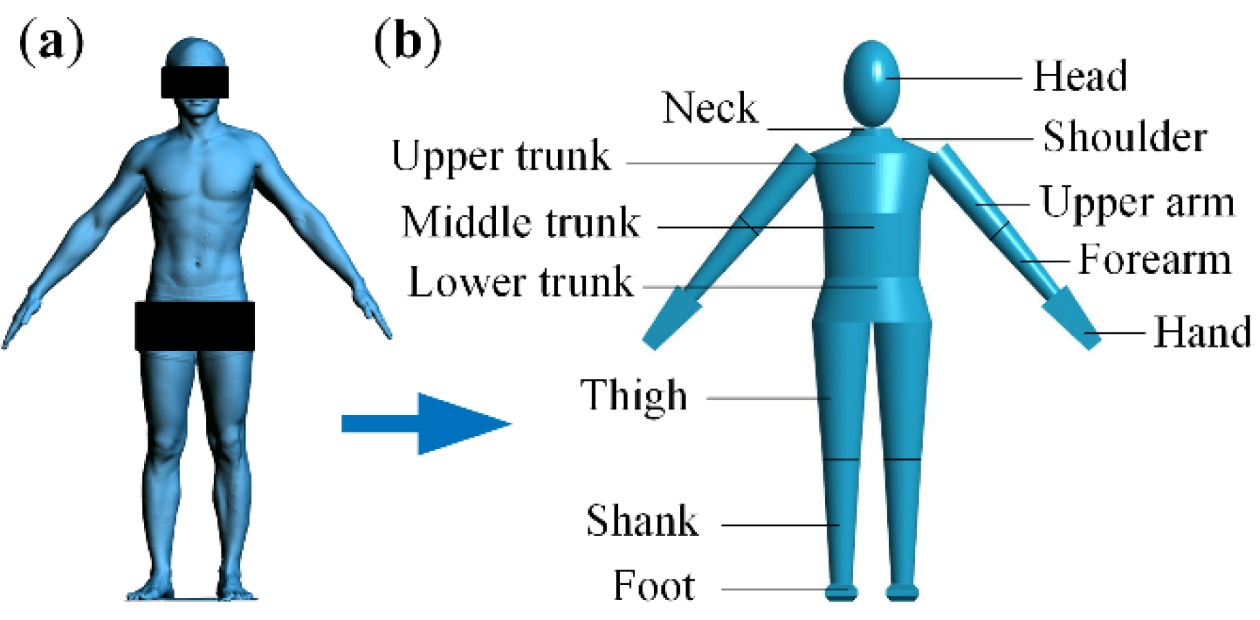
2.2. Rigid-Body Dynamic Model of Human Swimming Based on the Newton-Euler Approach

The dynamic process of human swimming (Figure 2) can be equivalently described by the Newton-Euler equations. Specifically, by considering the whole human body as a rigid body, the translational motion in the global coordinate system can be determined by Newton’s second law:
M sub s ¨ G = F ,
where M sub is the mass of the subject, s G = ( x G , y G , z G ) T is the displacement vector of the subject’s center of gravity (COG), and F denotes the external force vector acting on the human body. The external force includes the gravity force F G , the normal drag force F n , the tangential drag force F t , the added mass force F a , and the buoyancy F b acting on the human body. Each force is the vector sum of the corresponding forces acting on the model segments, which will be detailed in Section 2.3.
The rotational motion of the human body during swimming can be described by the Euler equations in the COG-principle-axes coordinate system:
{ J x ^ ω ˙ x ^ + ( J z ^ J y ^ ) ω y ^ ω z ^ + J ˙ x ^ ω x ^ = M x ^ , J y ^ ω ˙ y ^ + ( J x ^ J z ^ ) ω x ^ ω z ^ + J ˙ y ^ ω y ^ = M y ^ , J z ^ ω ˙ z ^ + ( J y ^ J x ^ ) ω x ^ ω y ^ + J ˙ z ^ ω z ^ = M z ^ ,
where x ^ , y ^ , z ^ are the three principal axes of inertia of the human body; J i and ω i   ( i = x ^ , y ^ , z ^ ) denote the moment of inertia and the angular velocity of the human body about the i axis, and M i   ( i = x ^ , y ^ , z ^ ) indicates the total external moment about the i axis applied to the human body. Note that due to the relative movements among human body segments during swimming, the moment of inertia about each principal axis is not constant, which gives rise to the last term on the left side of Equation (2).

2.3. Modelling of the Fluid Forces

The fluid force acting on human segments during swimming includes two parts: the hydraulic resistance and the buoyancy, where the former can be further categorized into the passive drag (PD) and the active drag (AD) [43]. The passive drag is the hydrodynamic resistance that a non-swimming subject receives when being towed through the water. If the subject maintains a streamlined glide when being towed, the limbs are parallel to the trunk. In such a scenario, the passive drag force is along the longitudinal axis of each body segment, and thus, the passive drag force F pd is equivalent to the tangential drag force F t .
Active drag is the hydrodynamic resistance acting on the self-propulsive swimmer. Active drag can be considered as a composite quantity that includes the passive drag, the additional resistive drag, and the propulsive thrust caused by swimming strokes. The active drag force can be equivalently viewed as the vector sum of the total drag force (including the tangential drag and the normal drag) and the added mass force. In this research, to understand the interaction mechanism between the human body and the current during swimming, active drag is evaluated.

2.3.1. Passive Drag

The passive drag consists of the following components: the air drag, the friction drag, the pressure drag, and the wave drag, among which the air drag is usually ignorable. Analytical modeling of the other three drag components is also challenging, which calls for a large number of parameters that are usually difficult to be determined. Usually, the passive drag force is defined by
F pd = F t = 1 2 C pd ρ | v | v A ,
in Equation (3), C pd is the equivalent passive drag coefficient, which is a dimensionless quantity and is a function of the Reynolds number of the body, ρ is the density of the water, v is the absolute velocity of the body relative to the currents, and A is the orthogonal projection area of the human body in the direction of motion.

2.3.2. Active Drag

The active drag is closely related to the relative movements of the human joints during swimming. The active drag force F ad consists of the tangential drag force F t (i.e., the passive drag force F pd ), the normal drag force F n , and the added mass force F a , given by
{ F ad = F pd + F n + F a , F n = 1 2 C n ρ A | v | v , F a = Δ m a ,
where F n is perpendicular to the longitudinal axis of each body segment, C n , Δ m , and a are the equivalent drag coefficient in the normal direction, the added mass (to be introduced later), and the acceleration of the body segment, respectively.
In this research, the abovementioned fluid forces acting on each body segment will be analyzed via infinitesimal bodies (Figure 3). Specifically, each body segment is divided into thin plates along the longitudinal axis. For each divided plate, the fluid forces, which are assumed to act on the plate center, are calculated according to its posture, velocity, acceleration, angular velocity, and angular acceleration.
For the head and the limbs (excluding the hands and the feet), thin elliptical plates are taken along the longitudinal axis (Figure 3a). The unit vector along the minor and major axes of an elliptical plate are denoted respectively by e 1 and e 2 , and the corresponding radii are r 1 and r 2 , respectively (Figure 3b); the circumference and the thickness of an elliptical plate are denoted by c and d l , respectively. The velocity component of the center of an elliptical plate along the longitudinal axis is represented by v t , and the current velocity component along the longitudinal axis is represented by v ct . With these notations, the tangential drag force F t of an elliptical plate can be expressed as
F t = 1 2 C pd ρ ε c d l [ | v t v ct | ( v t v ct ) ] .
The normal drag F n is given by
F n = 1 2 C n ρ ε d l { r 2 ( r 2 r 1 ) e [ | v n v cn | ( ( v n v cn ) e 1 ) ] e 1 + r 1 ( r 1 r 2 ) e [ | v n v cn | ( ( v n v cn ) e 2 ) ] e 2 } ,
where v n is the velocity component of the center of an elliptical plate perpendicular to the longitudinal axis, and v cn is the current velocity component perpendicular to the longitudinal axis. The superscript coefficient e represents the eccentricity of the ellipse, defined as e = r 1 2 r 2 2 / r 1 . In Equations (5) and (6), the immersion ratio of an elliptical plate is denoted by ε , which is defined as the ratio of the immersed lateral surface area to the overall lateral surface area of the divided elliptical plate. In the numerical program, by further dividing the lateral surface of the elliptical plate into tiny quadrilaterals and by evaluating the z coordinate of the quadrilateral center (denoted by z q ), the immersion ratio can be calculated as the number of quadrilaterals with negative z q value over the number of all quadrilaterals in a divided elliptical plate.
The added mass is the additional inertia added to the human body due to the fact that a body segment in unsteady motion (i.e., accelerating or decelerating) must move some volume of the surrounding water as it moves through it. The added mass force F a is defined as
F a = C a ρ ε d l π [ r 2 2 ( a n e 1 ) e 1 + r 1 2 ( a n e 2 ) e 2 ] ,
where C a denotes the equivalent coefficient for the added mass effect; a n is the acceleration component of the center of an elliptical plate perpendicular to the longitudinal axis.
For the hands and the feet (Figure 3d–f), slender cuboid elements are divided along the longitudinal axis. Similar to the elliptical plate, the fluid force F t , F n , and F a can be derived:
F t = 1 2 C pd ρ ε d l [ 2 ( w + h ) ] [ | v t v ct | ( v t v ct ) ] ,
F n = 1 2 C n ρ ε d l { w [ | v n v cn | ( v n v cn ) e 1 ] + h [ | v n v cn | ( v n v cn ) e 2 ] } ,
F a = C a ρ ε w h d l [ ( a n e 1 ) e 1 + ( a n e 2 ) e 2 ] ,
where w , h , and d l are the width, height, and the thickness of a cuboid, respectively.

2.3.3. The Buoyancy

The buoyancy acting on a divided elliptical plate F b can be calculated by integrating the hydraulic pressure force over the lateral surface of an elliptical plate. For a tiny quadrilateral, the pressure force yields
F b = ρ g z q d s e n ,
where d s denotes the area of the quadrilateral, e n represents the unit vector normal to the quadrilateral. Calculation of the buoyancy for a divided cuboid is exactly the same as that for a divided elliptical plate and is not repeated.

2.3.4. Reduction of the Force System

By moving all the fluid forces to the COG of the human body and calculating the resultant force, the external force vector F locating at the right-hand side of Equation (1) can be obtained. Meanwhile, by calculating the couple moments induced by force relocation and through decomposition, the external moments M i   ( i = x ^ , y ^ , z ^ ) on the right-hand side of Equation (2) can be determined.

2.4. Calculation Processes

Based on the established dynamic model of human swimming, numerical calculations can be performed, providing that the kinematic data are available. Here, the relative body motion in a cycle is given in the human-body coordinate system O b x b y b z b based on the recorded videos of human swimming [30]. The calculation process is detailed in Appendix A.

3. Freestyle and Breaststroke Swimming in the Presence of Currents: A Case Study

In this section, freestyle and breaststroke swimming are analyzed in the presence of currents. The effects of the currents on the swimming performance are evaluated, including the swimming direction, the swimming speed, and the propulsive efficiency. Particularly, the underlying mechanism that induces the turning of swimming is interpreted.

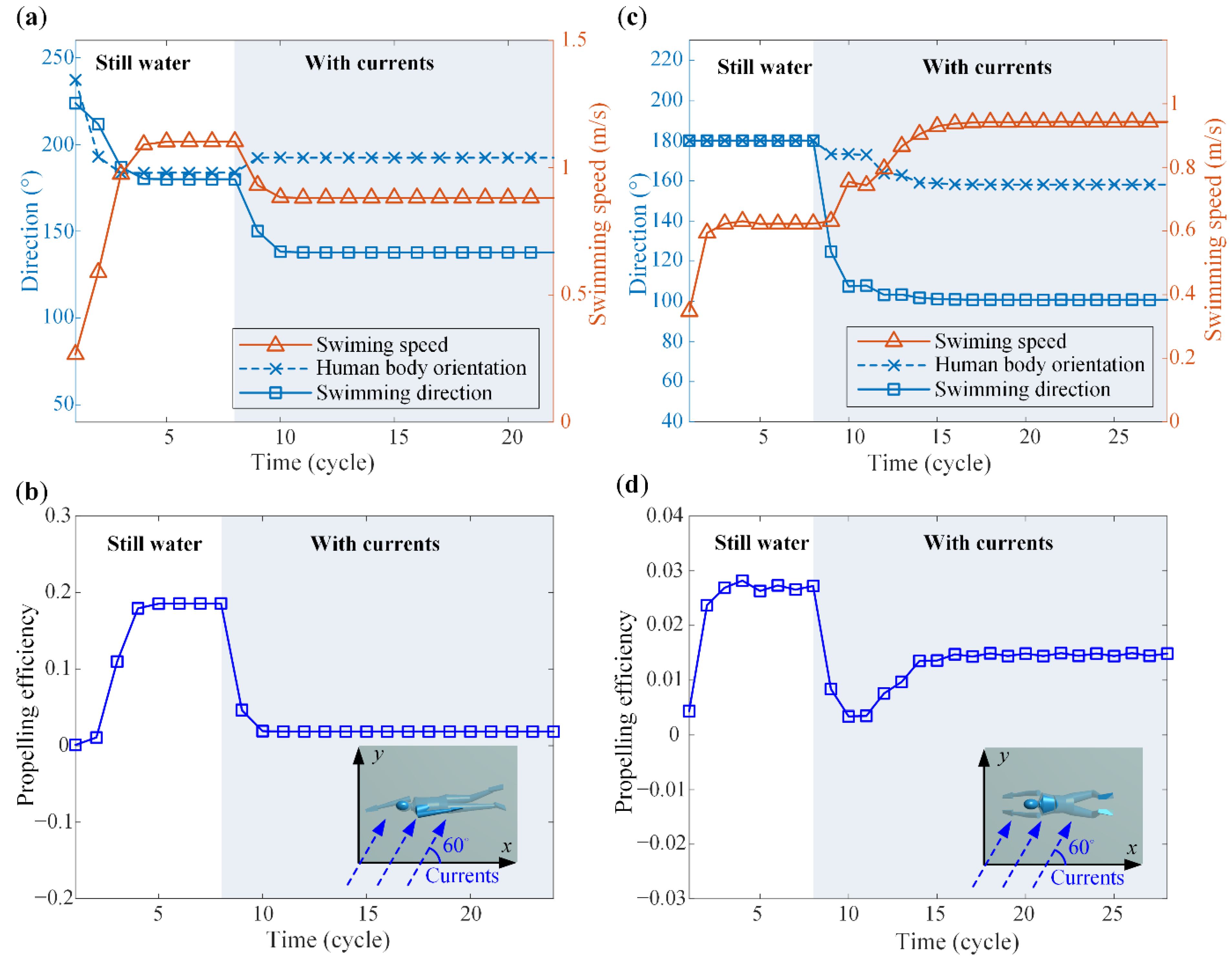
3.1. Swimming Performance Evaluation

In addition to the geometric parameters and the densities listed in Table 2, the fluid drag coefficients for all segments need to be prescribed. According to the body segment shape and the Reynolds number during swimming ( 4 × 1 0 6 ) and by referring [30,44,45], the fluid drag coefficients are set as C t = 0.036 , C n = 1.3 , and C a = 0.85 . The kinematic data of human swimming also come from [30]. The iteration time step of the calculation in this research is set to be 500 steps per swimming cycle. The currents are assumed to be parallel to the horizontal plane, i.e., the current has no component along the z direction.
For easy description, the following definitions are set forth: the current direction θ is defined as the angle from the x axis to the current (see Figure 2); the swimming direction is defined as the angle from the x axis to the direction of COG movement; the human body orientation is defined as the angle from the x axis to the principle axis of inertia x ^ . In this research, these angles and direction are defined within the horizontal plane, with the counterclockwise direction specified as positive. The average velocity of the COG in a swimming cycle is called the swimming speed. The propulsive efficiency P is defined as:
P = F slide v human W drag .
Note that the concept of propulsive efficiency is first proposed by Toussaint [46] in 1988. In Equation (12), v human , F slide , and W drag respectively denote the forward velocity of the human body (i.e., the component of swimming speed in the direction of human body orientation), the fluid drag that the swimmer receives when sliding in the water with a fixed posture at speed v human , and the average amount of mechanical power consumed by the swimmer against all fluid force in a cycle. It is a dimensionless value that describes the ratio of the power consumed by the swimmer in the forward direction to the total consumed power.
In the studied case, the current velocity in the first eight swimming cycles is assumed to be zero, i.e., still water. Generally, for both freestyle and breaststroke swimming, steady-state can be achieved within the first eight cycles, and the swimming direction is stabilized at 180 ° , i.e., the negative direction of the x axis. After the eighth cycle, the current velocity is set to be | v c | = 1 height / cycle , and the current direction is θ = 60 ° . Note that in the simulation program, all data are dimensionless. The current speed is non-dimensionalized by the subject’s height and the swimming cycle, which converts the unit of the current velocity into (height/cycle). However, for convenience, all the swimming performances are evaluated in standard units. Note that the current velocity v c generally varies between 0 m/s and 3.1 m/s in open water [47]. The prescribed current velocity | v c | = 1 height / cycle corresponds to 0.88 m/s, which is a reasonable choice to ensure effective swimming of the human, and meanwhile, to clearly demonstrate the effects of currents on freestyle and breaststroke swimming performance. It should be emphasized that the joint motions will not adaptively adjust with respect to the current condition; rather, they remain the same for each cycle.
Figure 4 displays the time histories of the swimming speed, the human body orientation, the swimming direction, and the propulsive efficiency P . The regions when the currents are applied are denoted by shade. Note that the results in still water agree well with those obtained through the SWUM software (with the same human body geometric model) [30], suggesting the correctness of the refined model and the numerical calculation process. Note that after the eighth cycle, the currents impose evident effects on swimming performance. Specifically, for freestyle swimming, the human body would turn counterclockwise due to the currents, and the human body orientation stabilizes at 192 ° ultimately. With currents, the swimming direction is no longer consistent with the human body orientation; the swimming direction turns clockwise to 137 ° . In addition to the direction changes, the 60 ° currents also exert negative effects on the swimming speed and the propulsive efficiency. The swimming speed is reduced from 1.10 m / s in still water to 0.88 m / s in the presence of currents, and the propulsive efficiency drops dramatically to 0.02. For breaststroke swimming, the human body would turn clockwise to 158 ° , which is in contrast to freestyle swimming. The swimming direction also turns clockwise to 100 ° . Note that although the swimming speed increases by 51.61 % to 0.94 m / s due to the contribution of the current along with the human body orientation, the propulsive efficiency still experiences a reduction from 0.027 to 0.015 because the human swims with current-negative [39], i.e., the current component along the human body is opposite to the human body orientation.
It is also worth pointing out that due to the intrinsic differences in swimming strokes, the swimming speed and the propulsive efficiency of the breaststroke swimming in still water are much lower than those of freestyle swimming. This agrees with our knowledge that the freestyle is a more efficient stroke than the breaststroke [48]. The higher active drag during the breaststroke results in lower propulsive efficiency compared to freestyle swimming. The observed differences in swimming performance between freestyle and breaststroke are consistent with [49]. Nevertheless, with the same currents given in this case, the swimming speed and the propulsive efficiency of breaststroke swimming become comparable to those of freestyle swimming, which can be attributed to the opposite turning trends of the human body orientation in freestyle and breaststroke swimming.

3.2. Visualization of the Calculation Results

Based on the dynamic model and the obtained results, animation of freestyle and breaststroke swimming under the given current condition can be made (electronic supplementary material, Video S1 and S2). The blue arrow in the video indicates the direction of the current applied after the eighth cycle. The generated animations provide a vivid demonstration of the swimming behavior under the current condition.

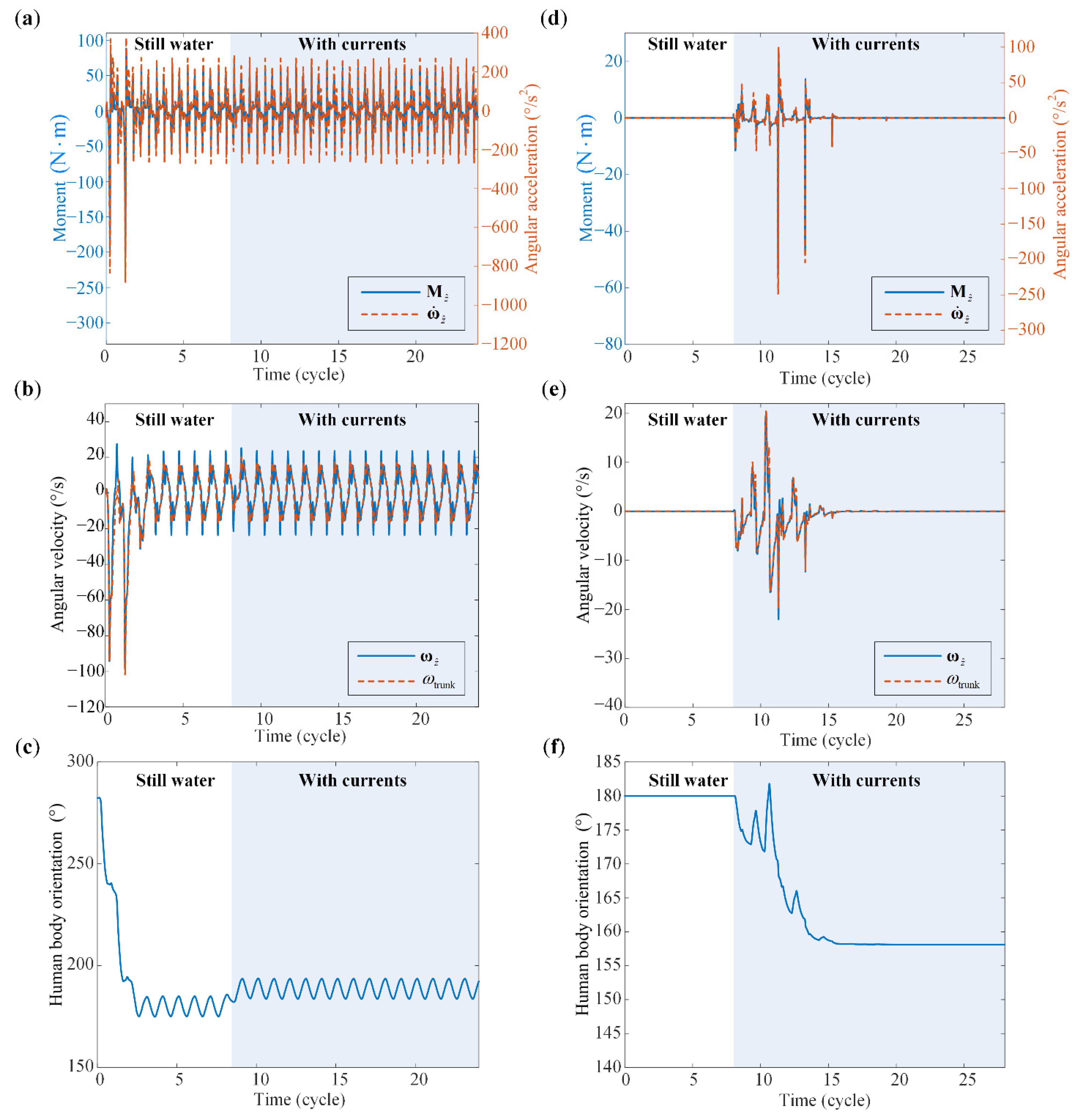
3.3. Swimming Direction Evolution: A Mechanical Explanation

As shown in Figure 4, the human body would turn to different directions in freestyle and breaststroke swimming under the same current condition, which gives rise to discrepancies in swimming performance. Hence, it is necessary to understand the underlying mechanics that triggers the turning. To this end, the following physical quantities are evaluated: M z ^ , the fluid moment applied to the human body about the principal axis of inertia z ^ ; ω ˙ z ^ , the angular acceleration of the human body about the z ^ axis; ω z ^ , the angular velocity of the human trunk about the z ^ axis; ω trunk , the change rate of human trunk orientation; and θ trunk , the human trunk orientation with respect to the x axis. Figure 5 displays the time histories of these quantities, from which the fundamental mechanism can be uncovered.

3.3.1. The Change of Fluid Moment Caused by Currents

Force or moment is the fundamental reason that induces the change of an object’s motion state. For freestyle swimming, the limbs on both sides of the sagittal plane swing alternately, resulting in periodic fluctuation of M z ^ in still water (Figure 5a). For breaststroke, the joint motions are symmetrical about the sagittal plane, hence, M z ^ remains zero in still water (Figure 5d). At the eighth cycle, the appearance of currents induces a slight change on M z ^ for freestyle swimming while, for breaststroke swimming, the currents completely break the balance of M z ^ . The fluid moment would return stabilization after a few cycles.
The marked differences in the fluid moment M z ^ and the effects of currents on M z ^ are owing to the intrinsic discrepancies of the two swimming strokes. Note that the fluid drags acting on the human body are mainly determined by the relative velocity of the limbs with respect to the current. Although the current condition is identical for the two strokes, the joint motions are qualitatively different, which results in significant differences in the relative velocities of the limbs, and hence, the fluid moments M z ^ .

3.3.2. The Change of Angular Velocity Caused by Fluid Moment

According to the Euler equations in Equation (1), ω z ^ is affected by M z ^ , J x ^ , J y ^ , J z ^ , ω x ^ , and ω y ^ . During swimming, the human trunk would rotate about the three main principal axes of inertia, so ω x ^ , ω y ^ and ω z ^ are coupled together. Moreover, J x ^ , J y ^ , and J z ^ are not constants during swimming and would change over time, which have an impact on ω z ^ as well. Nonetheless, the fluid moment M z ^ is still the major factor that influences the variation of the angular velocity according to the law of rotation.
Figure 5a,d provide a comparison between the fluid moment M z ^ and the angular acceleration ω ˙ z ^ for both strokes, which reveals a good agreement in terms of the qualitative trend and the quantitative magnitudes. This, therefore, suggests that there is a convincible relation between the fluid moment and the rotation motion. When analyzing this relation, it is acceptable to ignore the variations of the inertia moments and the effects of the angular velocities.

3.3.3. The Change of Human Body Orientation Caused by the Angular Velocity

The angular velocities around the principal axes of inertia determine the human body orientation. Due to the angular acceleration about the principal axis of inertia z ^ (i.e., ω ˙ z ^ ), an angular velocity ω z ^ will be generated. Here, the influences of ω x ^ and ω y ^ are not considered either. Figure 5b,e display the time histories of the angular velocity ω z ^ and the change rate of the human trunk orientation (i.e., ω trunk ) for freestyle and breaststroke swimming. It can be seen that for both strokes, ω trunk and ω z ^ are in good agreement both qualitatively and quantitatively, manifesting the reasonability for neglecting ω x ^ and ω y ^ . With the generated angular velocity ω z ^ , the human body would rotate accordingly (Figure 5c,f). The human trunk would turn counterclockwise in freestyle swimming and clockwise in breaststroke swimming.
Overall, the above analyses reveal that the fluid moment is the major factor that determines the human body orientation during swimming. When the current is applied, the fluid moments would experience a change, which thus induces an angular acceleration and angular velocity about the principal axis of inertia z ^ ; with the generated angular velocity, the human trunk turns accordingly. The differences in the turning direction and the turning angle for the two strokes are caused by the discrepancies in fluid moments M z ^ , which, more fundamentally, is a result of the differences in joint motions of the two strokes. Note that the above mechanics analyses aim at a particular current condition. It is then necessary to perform a comprehensive investigation into the effects of the current direction and speed on the swimming performance, which is presented in the next section.

4. Effects of Currents on Freestyle and Breaststroke Swimming: Parameter Studies

To get a comprehensive understanding of the effects of currents on freestyle and breaststroke swimming, a systematic parameter study is carried out. The current velocity is allowed to vary from 0 to 1.5 height / cycle , and the current direction range between [ 0 , 180 ° ] . The examined performance indexes include the human body orientation, swimming direction, swimming speed, and propulsive efficiency.

4.1. Freestyle Swimming Performance

Figure 6 displays the results of the parameter study for freestyle swimming. Reading from the contour plots in the current velocity-direction plane, the following characteristics are concluded.
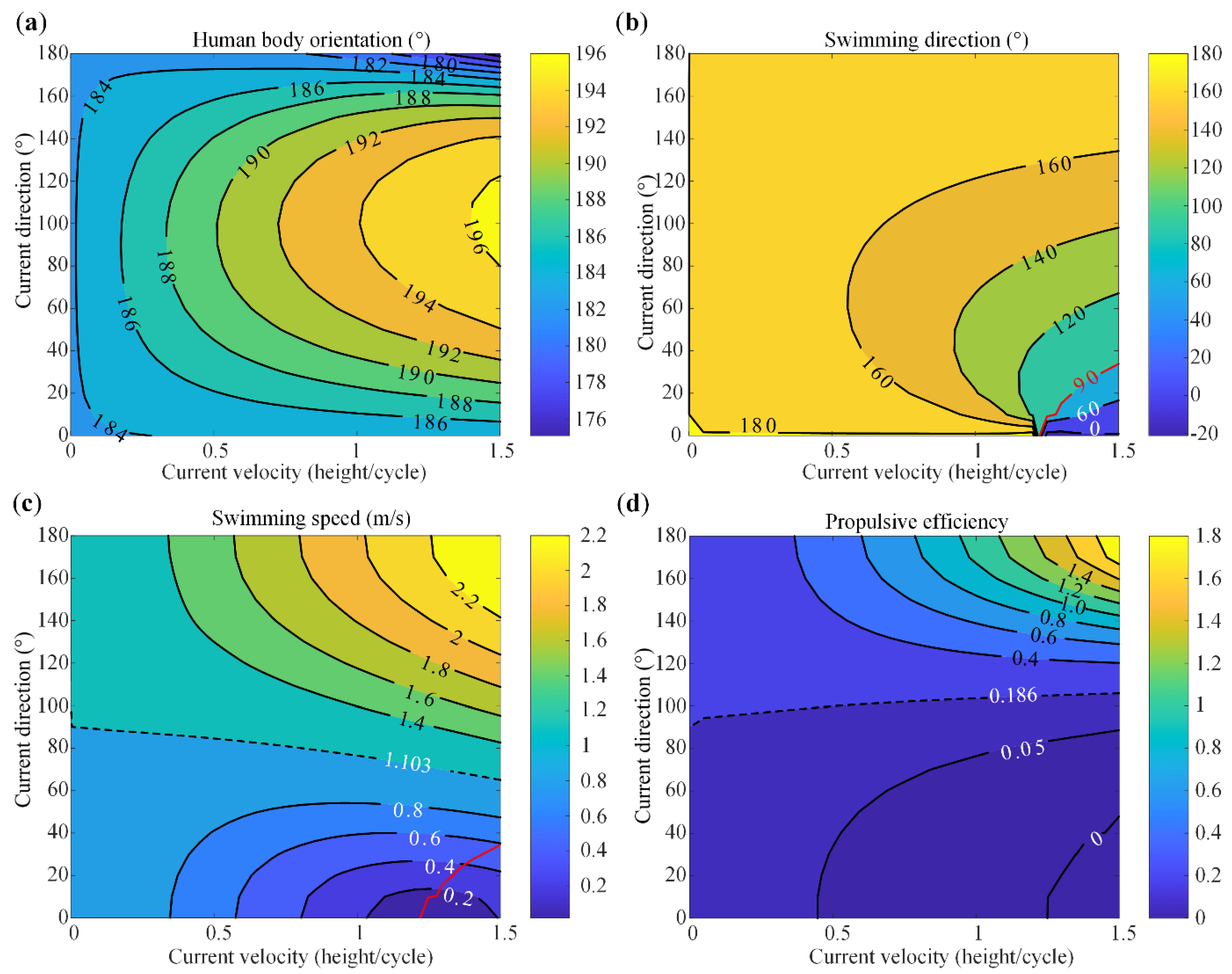
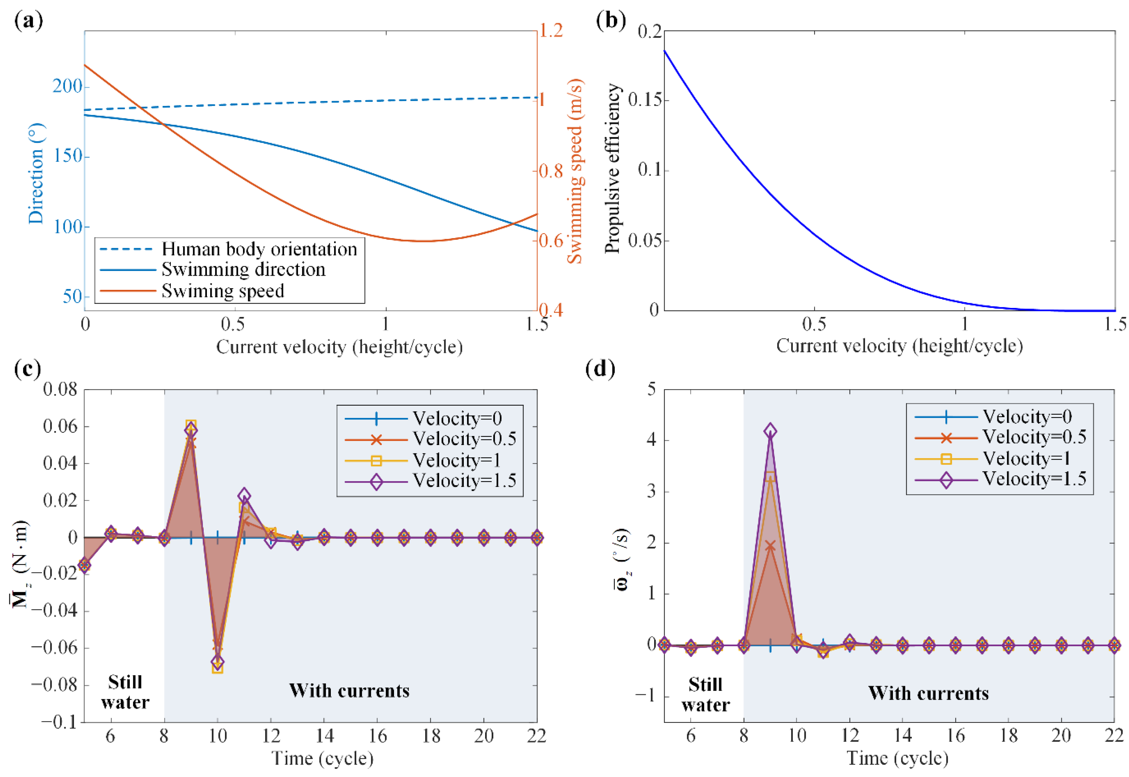
  • For all current conditions within the range, the human trunk turns counterclockwise. The maximum orientation angle is 196.4 ° , which is achieved at the 100 ° current with velocity 1.5 height/cycle (Figure 6a).
  • In contrast to the human body orientation, for all current conditions, the human swimming direction turns clockwise (Figure 6b).
  • In terms of the swimming speed, the current can play either a positive role or a negative role. Taking the swimming speed in still water (i.e., 1.103 m/s, denoted by black dashed lines) as a reference, currents with a relatively larger angle (say, θ > 90 ° ) could contribute to the swimming speed (Figure 6c).
  • The 90 ° red curve (Figure 6b,c) corresponds to the current conditions under which the human swims along the y direction, and the human body’s absolute speed along the x direction is zero under the action of currents. Crossing this critical curve to the right, the human body can no longer resist the drag of currents to swim forward (i.e., to swim toward the negative x direction).
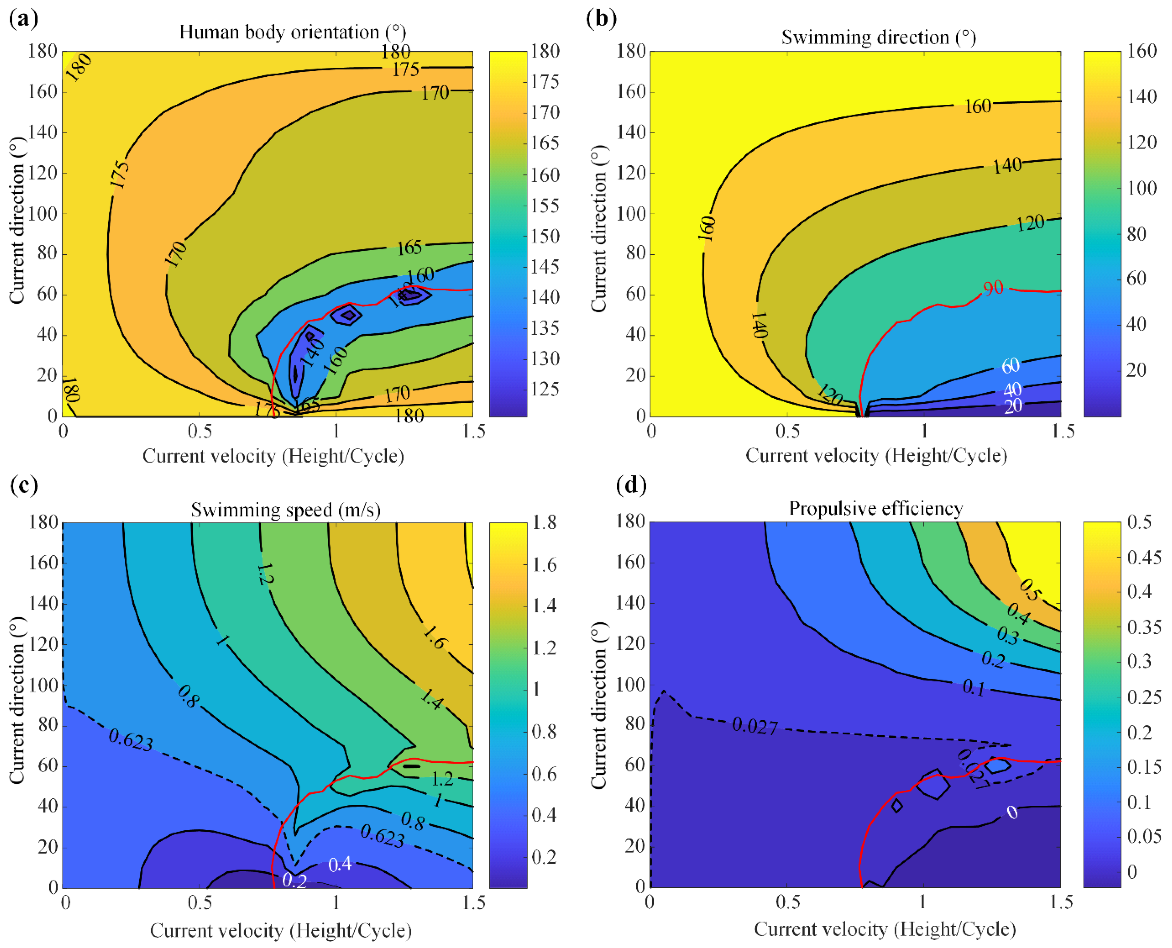
  • For a fixed current direction, the human body orientation angle increases with the current velocity (i.e., more counterclockwise, Figure 6a), while the swimming direction angle tends to diminish (i.e., more clockwise, Figure 6b). Depending on the current direction, the swimming speed climbs with the current velocity when the current direction is relatively large and drops when the current direction is relatively small (Figure 6c).
  • For a fixed current velocity, with the increase of the current angle θ the counterclockwise turning angle of the human trunk grows first and then declines. Particularly, if the current angle is 0 ° or 180 ° , the human trunk does not turn (Figure 6a). In terms of the swimming speed, it always rises with the current angle (Figure 6c).
  • The current could serve as either a positive or negative factor in terms of the propulsive efficiency (Figure 6d). Particularly, the propulsive efficiency can decrease to zero or negative when the counter-current velocity is too high for the human to achieve net velocity along with the human body orientation.
We further examine two cases to exemplify the underlying mechanisms. In Case I, the current direction is fixed to 40 ° , and the current velocity is allowed to vary from 0 to 1.5 height/cycle (Figure 7); and in Case II, the current velocity is fixed to 1 height/cycle, and the current direction varies between 0 ° and 180 ° (Figure 7). To interpret the absolute rotation of the human trunk, the average fluid moment per cycle applied to the human body about the global z axis ( M ¯ z ) and the average angular velocity of the human body per cycle about the z axis ( ω ¯ z ) are illustrated under different current conditions.
Figure 7a indicates that for the 40 ° current, the human body turns counterclockwise, while the swimming direction turns clockwise. With the increase of the current velocity, both turning angles grow. Figure 7c,d provide a mechanical explanation for the evolution of the turning angles. As the current velocity increases from 0 to 1.5 height/cycle, M ¯ z enlarges in general, giving rise to a significant boost of the average angular velocity ω ¯ z , i.e., the human body would turn counterclockwise more. On the other hand, under the joint action of the currents (at 40 ° ) and the joint motions, the swimming direction will turn clockwise more when the current velocity is higher (Figure 7a). Currents with relatively high velocity will increasingly hinder the human swimming due to the increased drag, thus diminishing the swimming speed and the efficiency. Particularly, if the current velocity is too high, although the absolute swimming speed is increased again (Figure 7a), the swimmer could achieve little net speed along this human body orientation, inducing a close-to-zero propulsive efficiency (Figure 7b).
Similar analyses can also be performed in case 2, i.e., fixing the current velocity to 1 height/cycle and allowing the direction to be variable. When the current direction is parallel to the human body orientation, the fluid drag is approximately symmetric to the sagittal plane of the human body. Hence, the average moment applied to the human body about the z axis ( M ¯ z ) is very low. As the current direction varies from 0 ° to 180 ° , M ¯ z and ω ¯ z will climb first and descend then (Figure 8c,d). As a consequence, the counterclockwise turning angle of the human body orientation, as well as the clockwise turning angle of the swimming direction, increases first and then decreases (Figure 8a). On the other hand, when the current angle is acute, the human swims with current-negative, giving rise to relatively low swimming speeds and minute propulsive efficiencies. As the current angle increases, the swimming condition gradually changes from current-negative to current-positive, which significantly improves the swimming speed (Figure 8a) and the propulsive efficiency (Figure 8b).
It’s worth noting that with constant current velocity, the human body orientation relative to the current direction is not unique when the absolute current direction is different (Figure 8a). This is due to the fact that the fluid forces and moments mainly depend on the current velocity relative to the human body, rather than the absolute current velocity. Specifically, the swimming speed of the human body, and hence, the relative velocity of the human body with respect to the current, are determined by both the stroke of the human body and the currents. Currents not only affect the velocity of swimmer’s COG but also induce the rotation of the human body. Therefore, with constant current velocity but different absolute current directions, the stabilized absolute swimming speeds are different (Figure 8a). The differences in the absolute swimming speed would result in different relative velocities of the human body with respect to the currents, which further alter the fluid forces and moments acted on the human body. When different fluid moments act on the human body about the global z-axis, the human body would rotate differently. This explains why the relative angles between the currents and the human body are different when the current directions are different. However, it should be emphasized that with different current directions the relative speed between the human body and the current (denoted by V relative ) will always stabilize at 1.103 m/s, which is the swimming speed in still water, and the angle between the human body and V relative keeps at about 183.8 ° . This, from another perspective, validates our results. Similar analyses can be performed in breaststroke swimming.

4.2. Breaststroke Swimming Performance

Similarly, Figure 9 shows the effects of current directions and current velocities on breaststroke swimming performance. The overall trend is more complex than that of freestyle swimming. The following characteristics can be concluded from the contour plot.
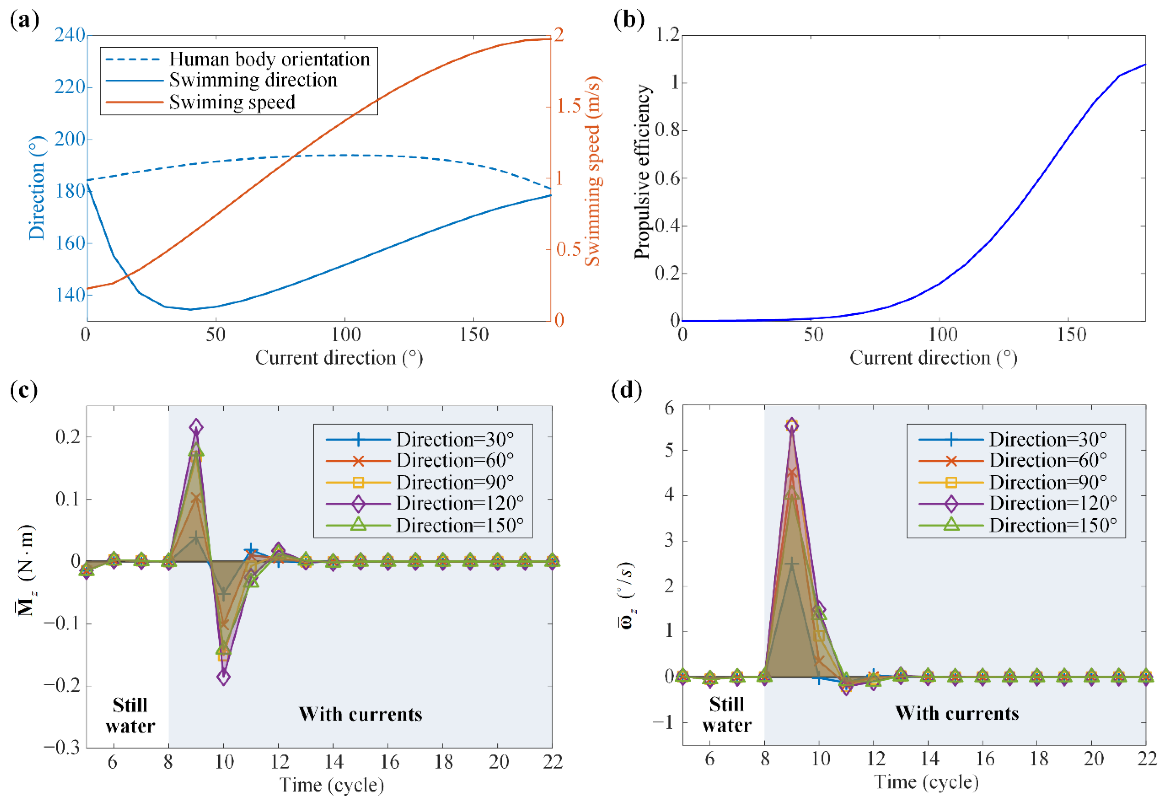
  • For all current conditions within the range, the human trunk turns clockwise.
  • With currents, the human swimming direction also turns clockwise (Figure 9b).
  • The currents can be either beneficial or detrimental to the swimming speed. With a relatively large current angle and current velocity, the swimming speed can significantly exceed the speed in still water, i.e., 0.623 m/s, denoted by the black dashed line in Figure 9c.
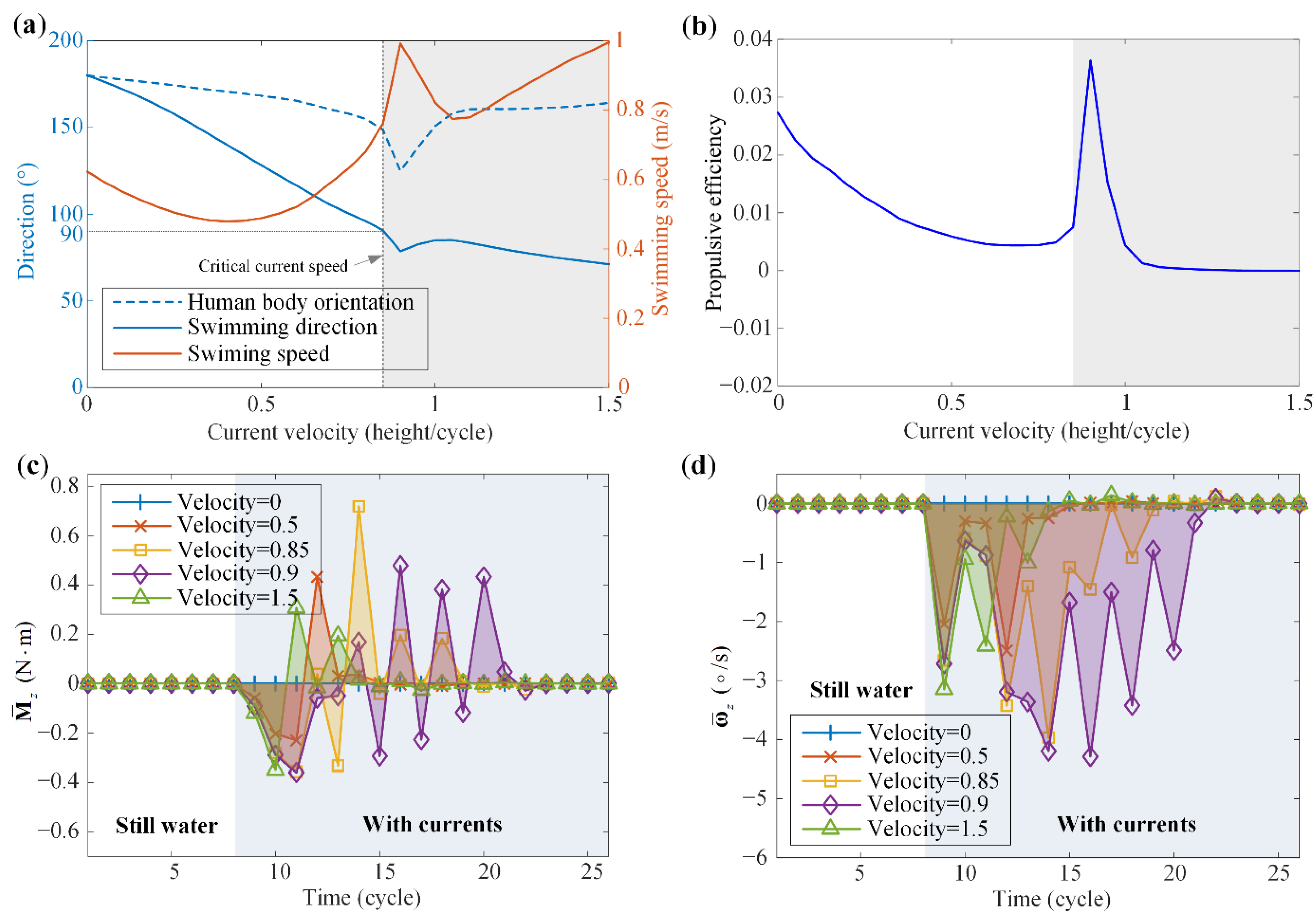
  • The 90 ° red curve (Figure 9) can also be identified in breaststroke swimming. This curve corresponds to the current conditions under which the human swims along the y direction, and the human body’s absolute speed along the x direction is zero under the action of currents. Crossing the critical curve to the right, the human body can no longer resist the drag of the currents to swim forward (i.e., to swim toward the negative x direction). Around the critical curve, the human orientation angle reaches the valley, with the minimum ( 125 ° ) being achieved at the 40 ° current with velocity 0.9 height/cycle (Figure 9a).
5.
For a fixed current direction, the increase of current velocity will enlarge the clockwise turning angle of the human trunk (i.e., more clockwise), until the critical current velocity (i.e., the critical curve) is reached (Figure 9a). Above the critical current velocity, the clockwise turning angle of the human trunk reduces. On the other hand, the swimming direction angle always decreases (i.e., more clockwise) with the current velocity (Figure 9b). In terms of the swimming speed, when the current angle is relatively large, the swimming speed grows as the current velocity increases; when the current angle is relatively small, the swimming speed drops first and then bumps up after crossing the critical current velocity (Figure 9c).
6.
For a fixed current velocity, with the increase of the current direction, the clockwise turning angle of the human trunk grows first and then declines (Figure 9a). For the swimming speed, it also increases with the current angle in general (Figure 9c).
7.
Similarly, the current could be either advantageous or disadvantageous to the propulsive efficiency (Figure 9d). For a relatively large current angle, the current is favorable to the propulsive efficiency. Note that the propulsive efficiency can also decrease to zero or negative when the counter-current velocity is too high.
Similar to freestyle swimming, two cases are studied to better understand the underlying mechanism of the current effects in breaststroke swimming. In Case III, the current direction is fixed at 40 ° , and the current velocity is allowed to vary from 0 to 1.5 height/cycle; in Case IV, the current velocity is set to be 0.5 height/cycle, and the current angle varies between 0 ° and 180 ° . Similarly, the average fluid moment per cycle applied to the human body about the z axis ( M ¯ z ) and the average angular velocity of the human body per cycle about the z axis ( ω ¯ z ) are examined.
In Case III, Figure 10a reveals that both the human body and the swimming direction turn clockwise. Before reaching the critical current velocity (0.85 height/cycle), both turning angles increase with the current velocity. It can be interpreted from Figure 10c,d that the average fluid moment M ¯ z and the average angular velocity ω ¯ z are proportional to the current velocity. Slightly above the critical current velocity, the swimming process needs more cycles to reach a steady state. When the current velocity is 0.9 height/cycle, more than 23 cycles are spent to arrive at a steady-state (Figure 10c,d), and the clockwise turning angle of the human trunk jumps to a peak ( 125.1 ° ) (Figure 10a). Accordingly, the swimming direction, the swimming speed, and the propulsive efficiency all experience an extreme point. If the current velocity continues increasing, the convergence time would be shortened again, resulting in the reduction of ω ¯ z , and hence, the decrease of the clockwise turning angle of the human trunk. The swimming speed and the propulsive efficiency also receive a fast decline and then return to their previous trends. Note that with relatively high current velocity, the swimming speed improves significantly, while the net speed along the human body orientation is tiny, which further reduces the propulsive efficiency.
In Case IV, the current velocity (0.4 height/cycle) is lower than the critical value. With the increase of the current angle from 0 ° to 180 ° , M ¯ z and ω ¯ z first grow and then decline (Figure 11c,d), resulting in a similar trend of the clockwise turning angles of the human trunk and the swimming direction (Figure 11a). The increase of the current angle, on the other hand, fundamentally alters the swimming condition from current-negative to current-positive, thus gradually improving the swimming speed and the propulsive efficiency.

5. Summary and Conclusions

Human swimming is a complex dynamic process involving fluid-solid interaction. In this study, a multi-body dynamic model of the human is developed to understand the effects of currents on freestyle and breaststroke swimming performance. As a step forward from the previous research, the geometric model of the human body is refined, and the current conditions are included in modeling the fluid drags. The proposed model is of low cost for calculations, and the obtained results are of acceptable accuracy. Four performance indexes, namely, the human body orientation, the swimming direction, the swimming speed, and the propulsive efficiency, are examined in detail in this research, through both case studies and systematic parametric analyses.
It is revealed that the currents would significantly alter the swimming performance, both qualitatively and quantitatively. Generally, for freestyle swimming, the currents would rotate the human trunk counterclockwise, but turn the swimming direction clockwise; for breaststroke swimming, the currents would turn both the human body orientation and the swimming direction clockwise. Note that with different current conditions in both swimming strokes, although the human body orientation and the absolute swimming direction change, the relative speed of the human body with respect to the current keeps constant (equaling to the absolute human swimming speed in still water), and the angle between the human body and the relative velocity remains stable when the swimming motion reaches steady state. Depending on both the current condition and the joint motions, the current can be either advantageous or disadvantageous to the swimming speed and the propulsive efficiency. Particularly, for both strokes, there exist critical current conditions, crossing which, the swimming direction would be completely switched, inducing a close-to-zero or even negative propulsive efficiency, although the swimming speed may, instead, increase.
In addition to the above observations, the underlying mechanisms of the abovementioned turning behaviors are uncovered from a mechanics point of view. By examining the fluid moments and the swimming kinematics, say, the angular acceleration, the angular velocity, and the angular displacement, the positive correlation between them are established. In different current conditions, the change of the fluid moments applied to the principal axis of inertia ( z ^ ) axis and the global z axis is the most fundamental reason for the human body turning.
It is worth point out here that the identified relationships between the current condition and the swimming performance are specific to the subject of this study. If the geometric model of the human body, the relative body motions of the swimmer, and the fluid coefficients are subject to changes, the obtained qualitative/quantitative results may no longer hold. However, the proposed framework of dynamic modeling, numerical calculation, and parameter analysis would still apply, which makes the research more meaningful.
We also remark here that in this research, the relative body motions of the swimming are assumed to be invariant, i.e., the human body keeps carrying out a cyclic motion and cannot adaptively adjust the joint motions according to the current conditions. This ideal assumption, although not totally agreeing with the actual human swimming process, is of great importance in simplifying the problem and understanding the underlying mechanisms. On the other hand, this assumption could still make sense in some extreme cases. In the dark, for example, the human is unable to navigate and adjust the swimming motion adaptively to the current. Moreover, the results based on this ideal assumption are also conducive to the design and control of underwater exoskeletons [7].
Overall, this study provides a useful methodology for analyzing human swimming in current conditions. The effects of current direction and current speed on swimming performance are analyzed and interpreted. These findings should be verified by experiments based on humanoid swimming robots in the future. Other future research directions include biomechanical experiments on human limb coordination when swimming in currents, dynamic modeling and analysis of the human-exoskeleton coupled system during swimming, and a more accurate dynamic model under the Euler-Lagrange framework.

Supplementary Materials

The following are available online at https://www.mdpi.com/article/10.3390/machines10010017/s1, Video S1: Freestyle Swimming Animation, Video S2: Breaststroke Swimming Animation.

Author Contributions

Y.B. performed the human subject experiment, developed the model, carried out the computational simulations, and drafted the manuscript. H.F. conceived this study, was involved in the model development and data interpretation, critically revised the manuscript, and acquired funding for this work. J.X. supervised this research and acquired funding for this work. All authors have read and agreed to the published version of the manuscript.

Funding

This research is supported by the National Key Research and Development Project of China (Grant No. 2018YFB1307305) and the Shanghai Rising-Star Program under Grant No. 20QA1400800.

Institutional Review Board Statement

The study was conducted in accordance with the Declaration of Helsinki, and approved by the Institutional Review Board of Fudan University (protocol code FE21124, approved on 16 August 2021).

Informed Consent Statement

Informed consent was obtained from the subject involved in the study. Written informed consent has been obtained from the subject to publish this paper.

Data Availability Statement

All the data are shown in the tables, figures, and electronic supplementary material of this paper. The relative body motion data used in this paper are from the previous work of Nakashima et al. [30].

Conflicts of Interest

The authors declare that they have no competing interest.

Appendix A. Major Steps of the Numerical Calculation

The numerical calculation process is given in Figure A1, which include the following major steps:
Figure A1. The calculation process.
Machines 10 00017 g0a1
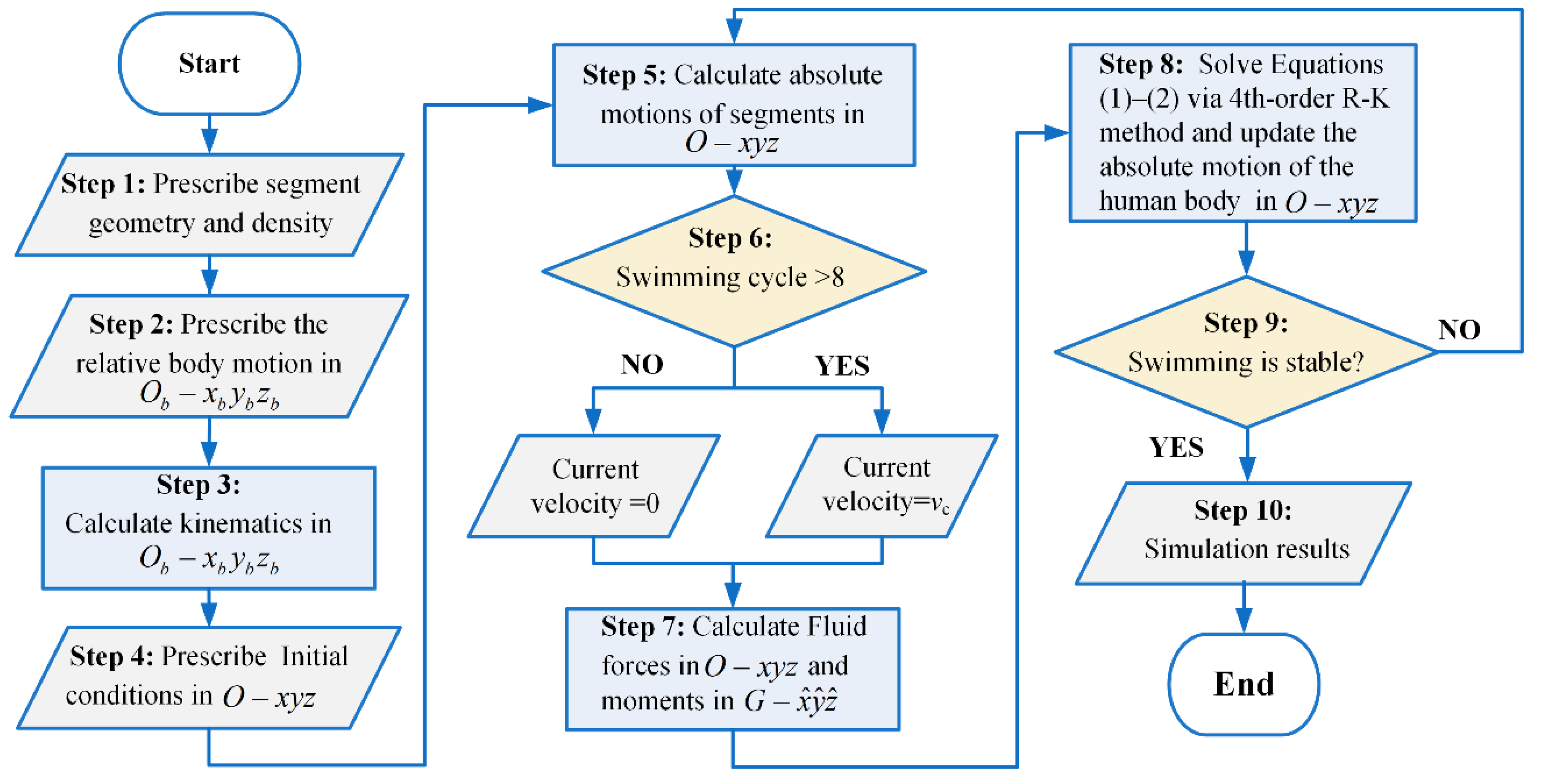
  • Step 2: Swimming is a cyclical motion. The relative body motion in a cycle is given in the human-body coordinate system O b x b y b z b based on the recorded videos of human swimming [30].
  • Step 3: Based on the given joint motions, calculate the position of the COG, the direction of the principal inertia axes, and the principal moments of inertia in a cycle in the human-body coordinate system O b x b y b z b .
  • Step 4: Set initial values in the global coordinate system O x y z , including the position and velocity of the COG, the direction of the principal axes of inertia, and the angular velocities about the principal axes of inertia. This actually initializes the configuration of G x ^ y ^ z ^ in the global coordinate system O x y z .
  • Step 5: Calculate the position, velocity, and acceleration of each segment in the absolute coordinate system O x y z .
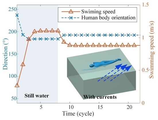
  • Step 6: Assume a static water environment in the first eight cycles, and apply currents with a velocity of v c from the ninth cycle.
  • Step 7: Calculate the fluid forces acting on each segment in O x y z and the fluid moments around the principal axes of inertia x ^ , y ^ , z ^ based on the fluid force model given in Equations (3)–(11).
  • Step 8: Solve Equations (1) and (2) via the 4-th order Runge-Kutta method to update the values in the global coordinate system O x y z of the next time step. Specifically, the position and velocity of the COG are calculated in O x y z , and the angular velocities about the principal inertia axes x ^ , y ^ , z ^ are calculated in G x ^ y ^ z ^ in each time step. For updating the directions of the principal axes of inertia in O x y z , a transformation matrix between the coordinate systems are employed.

References

  1. Wei, T.; Mark, R.; Hutchison, S. The Fluid Dynamics of Competitive Swimming. Annu. Rev. Fluid Mech. 2014, 46, 547–565. [Google Scholar] [CrossRef]
  2. Takagi, H.; Nakashima, M.; Sato, Y.; Matsuuchi, K.; Sanders, R.H. Numerical and experimental investigations of human swimming motions. J. Sports Sci. 2016, 34, 1564–1580. [Google Scholar] [CrossRef] [PubMed] [Green Version]
  3. Andersen, J.T.; Sanders, R.H. A systematic review of propulsion from the flutter kick–What can we learn from the dolphin kick? J. Sports Sci. 2018, 36, 2068–2075. [Google Scholar] [CrossRef]
  4. Cohen, R.C.Z.; Cleary, P.W.; Mason, B. Improving understanding of human swimming using smoothed particle hydrodynamics. In 6th World Congress of Biomechanics (WCB 2010), Singapore, 1–6 August 2010; Springer: Berlin/Heidelberg, Germany, 2010; pp. 174–177. [Google Scholar] [CrossRef]
  5. Silva, A.J.; Rouboa, A.; Moreira, A.; Reis, V.M.; Alves, F.; Vilas-Boas, J.P.; Marinho, D.A. Analysis of drafting effects in swimming using computational fluid dynamics. J. Sports Sci. Med. 2008, 7, 60–66. [Google Scholar] [PubMed]
  6. Akiyama, K.; Nakashima, M.; Ogasawara, I. Proposal of Walking in Water for ACL Injury Rehabilitation Program by Simulation. J. Biomech. Sci. Eng. 2010, 5, 461–471. [Google Scholar] [CrossRef] [Green Version]
  7. Wang, Q.; Zhou, Z.; Zhang, Z.; Lou, Y.; Zhou, Y.; Zhang, S.; Chen, W.; Mao, C.; Wang, Z.; Lou, W.; et al. An Underwater Lower-Extremity Soft Exoskeleton for Breaststroke Assistance. IEEE Trans. Med. Robot. Bionics 2020, 2, 447–462. [Google Scholar] [CrossRef]
  8. Bixler, B.S.; Schloder, M. Computational fluid dynamics: An analytical tool for the 21st century swimming scientist. J. Swim. Res. 1996, 11, 4–22. [Google Scholar]
  9. Bixler, B.; Riewald, S. Analysis of a swimmer’s hand and arm in steady flow conditions using computational fluid dynamics. J. Biomech. 2002, 35, 713–717. [Google Scholar] [CrossRef]
  10. Sato, Y.; Hino, T. CFD simulation of flows around a swimmer in a prone glide position. Jpn. J. Sci. Swim. Water Exerc. 2010, 13, 1–9. [Google Scholar] [CrossRef]
  11. Cohen, R.C.Z.; Cleary, P.W.; Mason, B.R.; Pease, D.L. Studying the effects of asymmetry on freestyle swimming using smoothed particle hydrodynamics. Comput. Methods Biomech. Biomed. Eng. 2020, 23, 271–284. [Google Scholar] [CrossRef]
  12. Cohen, R.C.Z.; Cleary, P.W.; Mason, B.R.; Pease, D.L. Forces during front crawl swimming at different stroke rates. Sports Eng. 2018, 21, 63–73. [Google Scholar] [CrossRef]
  13. Bixler, B.; Pease, D.; Fairhurst, F. The accuracy of computational fluid dynamics analysis of the passive drag of a male swimmer. Sports Biomech. 2007, 6, 81–98. [Google Scholar] [CrossRef] [PubMed]
  14. Sato, Y.; Hino, T. A computational fluid dynamics analysis of hydrodynamic force acting on a swimmer’s hand in a swimming competition. J. Sports Sci. Med. 2013, 12, 679–689. [Google Scholar]
  15. Harrison, S.M.; Cohen, R.C.Z.; Cleary, P.W.; Barris, S.; Rose, G. A coupled biomechanical-Smoothed Particle Hydrodynamics model for predicting the loading on the body during elite platform diving. Appl. Math. Model. 2016, 40, 3812–3831. [Google Scholar] [CrossRef]
  16. Cohen, R.C.Z.; Cleary, P.W.; Mason, B.R. Simulations of dolphin kick swimming using smoothed particle hydrodynamics. Hum. Mov. Sci. 2012, 31, 604–619. [Google Scholar] [CrossRef]
  17. Cohen, R.C.Z.; Cleary, P.W.; Mason, B.R.; Pease, D.L. The Role of the Hand during Freestyle Swimming. J. Biomech. Eng. 2015, 137, 111007. [Google Scholar] [CrossRef]
  18. Morais, J.E.; Sanders, R.H.; Papic, C.; Barbosa, T.M.; Marinho, D.A. The Influence of the Frontal Surface Area and Swim Velocity Variation in Front Crawl Active Drag. Med. Sci. Sports Exerc. 2020, 52, 2357–2364. [Google Scholar] [CrossRef]
  19. Toussaint, H.M.; Van Den Berg, C.; Beek, W.J. “Pumped-up propulsion” during front crawl swimming. Med. Sci. Sports Exerc. 2002, 34, 314–319. [Google Scholar] [CrossRef]
  20. Nicolas, G.; Bideau, B.; Bideau, N.; Colobert, B.; Le Guerroue, G.; Delamarche, P. A new system for analyzing swim fin propulsion based on human kinematic data. J. Biomech. 2010, 43, 1884–1889. [Google Scholar] [CrossRef]
  21. Kudo, S.; Yanai, T.; Wilson, B.; Takagi, H.; Vennell, R. Prediction of fluid forces acting on a hand model in unsteady flow conditions. J. Biomech. 2008, 41, 1131–1136. [Google Scholar] [CrossRef] [PubMed]
  22. Gourgoulis, V.; Aggeloussis, N.; Vezos, N.; Kasimatis, P.; Antoniou, P.; Mavromatis, G. Estimation of hand forces and propelling efficiency during front crawl swimming with hand paddles. J. Biomech. 2008, 41, 208–215. [Google Scholar] [CrossRef]
  23. Matsuuchi, K.; Miwa, T.; Nomura, T.; Sakakibara, J.; Shintani, H.; Ungerechts, B.E. Unsteady flow field around a human hand and propulsive force in swimming. J. Biomech. 2009, 42, 42–47. [Google Scholar] [CrossRef] [PubMed] [Green Version]
  24. Hochstein, S.; Blickhan, R. Vortex re-capturing and kinematics in human underwater undulatory swimming. Hum. Mov. Sci. 2011, 30, 998–1007. [Google Scholar] [CrossRef]
  25. Furmánek, P.; Redondo, J.M.; Carrillo, A.; Tellez, J.; Arellano, R.; Sanchez, M.A. Experiments and simulations of maximal sculling propulsion: Vorticity impulse in human biomechanics. In Proceedings of the Topical Problems of Fluid Mechanics 2016, Prague, Czech Republic, 10–12 February 2016; pp. 41–50. [Google Scholar]
  26. Phillips, C.W.G.; Forrester, A.I.J.; Hudson, D.A.; Turnock, S.R. Propulsive efficiency of alternative underwater flykick techniques for swimmers. Proc. Inst. Mech. Eng. Part P J. Sport. Eng. Technol. 2020, 235, 354–364. [Google Scholar] [CrossRef]
  27. Gojkovic, Z.; Ivancevic, T.; Jovanovic, B. Biomechanical model of swimming rehabilitation after hip and knee surgery. J. Biomech. 2019, 94, 165–169. [Google Scholar] [CrossRef] [PubMed]
  28. Shinohara, K. Swimmer simulation using robot manipulator dynamics under steady water. Nat. Sci. 2010, 2, 959–967. [Google Scholar] [CrossRef]
  29. SHINOHARA, K.; FURUKAWA, T.; YAGAWA, G. Simulation and Sub-Optimal Motion Planning of a Swimmer under Hydrodynamics. Trans. Jpn. Soc. Mech. Eng. Ser. C 2002, 68, 2643–2650. [Google Scholar] [CrossRef]
  30. Nakashima, M.; Satou, K.; Miura, Y. Development of Swimming Human Simulation Model Considering Rigid Body Dynamics and Unsteady Fluid Force for Whole Body. J. Fluid Sci. Technol. 2007, 2, 56–67. [Google Scholar] [CrossRef] [Green Version]
  31. Levin, S.; Albers, T.N.H.; Mitchener, K.J.; Richardson, G.; Tabellini, M.; Derviş, B.; Chaudhary, L.; Swamy, A.V.; Jedwab, R.; Johnson, N.D.; et al. Development of computer simulation software “swumsuit” to analyze mechanics of human swimming. Econ. Hist. Rev. 2019, 73, 202–246. [Google Scholar] [CrossRef]
  32. Akiyama, K.; Nakashima, M.; Miyoshi, T. Simulation Analysis of the Mechanical Body Load during Walking in Water. J. Environ. Eng. 2011, 6, 365–375. [Google Scholar] [CrossRef]
  33. Nakashima, M.; Hasegawa, T.; Matsuda, A.; Shimana, T.; Omori, K. 3D-CG Based Musculoskeletal Simulation for a Swimmer Wearing Competitive Swimwear. Procedia Eng. 2013, 60, 367–372. [Google Scholar] [CrossRef] [Green Version]
  34. Nakashima, M.; Hatakeyama, G.; Homma, M.; Ito, K. Simulation Analysis of Lift in Synchronized Swimming. J. Aero Aqua Bio-Mech. 2013, 3, 51–56. [Google Scholar] [CrossRef]
  35. Akiyama, K.; Nakashima, M. Development of widely useable simulator for optimization of walking form in water. Procedia Eng. 2010, 2, 3293–3298. [Google Scholar] [CrossRef] [Green Version]
  36. Nakashima, M.; Takahashi, R.; Kishimoto, T. Optimizing simulation of deficient limb’s strokes in freestyle for swimmers with unilateral transradial deficiency. J. Biomech. Sci. Eng. 2020, 15, 19–00467. [Google Scholar] [CrossRef]
  37. Nakashima, M.; Nemoto, C.; Kishimoto, T.; Terada, M.; Ikuat, Y. Optimizing simulation of arm stroke in freestyle for swimmers with hemiplegia. Mech. Eng. J. 2018, 5, 17–00377. [Google Scholar] [CrossRef] [Green Version]
  38. Baldassarre, R.; Bonifazi, M.; Zamparo, P.; Piacentini, M.F. Characteristics and challenges of open-water swimming performance: A review. Int. J. Sports Physiol. Perform. 2017, 12, 1275–1284. [Google Scholar] [CrossRef] [PubMed]
  39. Beaumont, F.; Taïar, R.; Polidori, G. Preliminary numerical investigation in open currents-water swimming: Pressure field in the swimmer wake. Appl. Math. Comput. 2017, 302, 48–57. [Google Scholar] [CrossRef]
  40. Plagenhoef, S.; Evans, F.G.; Abdelnour, T. Anatomical Data for Analyzing Human Motion University of Massachusetts -Amherst. Res. Q. Exerc. Sport 1983, 54, 169–178. [Google Scholar] [CrossRef]
  41. Chang, J.; Chablat, D.; Bennis, F.; Ma, L. Using 3D Scan to Determine Human Body Segment Mass in OpenSim Model. In International Conference on Digital Human Modeling and Applications in Health, Safety, Ergonomics and Risk Management; Springer: Berlin/Heidelberg, Germany, 2018; pp. 29–40. ISBN 9783319913971. [Google Scholar]
  42. Li, T.; Cai, W.; Zhan, J. Numerical investigation of swimmer’s gliding stage with 6-DOF movement. PLoS ONE 2017, 12, e0170894. [Google Scholar] [CrossRef]
  43. Zatsiorsky, V.M. (Ed.) Biomechanics in Sport; Blackwell Science Ltd.: Oxford, UK, 2000; ISBN 9780470693797. [Google Scholar]
  44. de Sousa, J.V.N.; de Macêdo, A.R.L.; de Amorim, W.F., Jr.; de Lima, A.G.B. Numerical Analysis of Turbulent Fluid Flow and Drag Coefficient for Optimizing the AUV Hull Design. Open J. Fluid Dyn. 2014, 4, 263–277. [Google Scholar] [CrossRef] [Green Version]
  45. Barrio-Perotti, R.; Blanco-Marigorta, E.; Argüelles-Díaz, K.; Fernández-Oro, J. Experimental evaluation of the drag coefficient of water rockets by a simple free-fall test. Eur. J. Phys. 2009, 30, 1039–1048. [Google Scholar] [CrossRef]
  46. Toussaint, H.M.; Beelen, A.; Rodenburg, A.; Sargeant, A.J.; de Groot, G.; Hollander, A.P.; van Ingen Schenau, G.J. Propelling efficiency of front-crawl swimming. J. Appl. Physiol. 1988, 65, 2506–2512. [Google Scholar] [CrossRef] [PubMed]
  47. Wilson, J.D.; Buffa, A.J.; Lou, B. College Physics Essentials; CRC Press: Boca Raton, FL, USA, 2019; ISBN 9780429323362. [Google Scholar]
  48. Seifert, L.; Carmigniani, R. Coordination and stroking parameters in the four swimming techniques: A narrative review. Sports Biomech. 2021. online. [Google Scholar] [CrossRef] [PubMed]
  49. Nakashima, M. Modeling the dynamics of human swimming. In Mining Smartness from Nature (CIMTEC 2008); Trans Tech Publications Ltd.: Freienbach, Switzerland, 2008; Volume 58, pp. 220–228. [Google Scholar] [CrossRef]
Figure 1. Geometric modeling of the human body. (a) 3D CAD model of the human subject based on point cloud data obtained via 3D scanning. (b) Multi-rigid-body model of the human body consisting of 18 segments.
Machines 10 00017 g001
Figure 2. Dynamic model of human swimming. Three coordinate systems are established, the global coordinate system o x y z , the human body coordinate system O b x b y b z b (the origin O b locates at the section center of the middle trunk root), and the COG-principle-axes coordinate G x ^ y ^ z ^ . The currents are within the O x y plane, and the angle from the x-axis to the water current direction is θ .
Machines 10 00017 g002
Figure 3. Illustration of the fluid forces acting on the head segment (modeled as an ellipsoid), the limb segments (modeled as truncated elliptical cones), and the hand/foot segments (modeled as frusta of a pyramid). (a) The ellipsoid and the truncated elliptical cone, where the divided elliptical plates are denoted. (b) Dimensions of a divided elliptical plate. (c) The hydraulic pressure force applied on a divided tiny quadrilateral. (d) The frustum of a pyramid, where the divided cuboid is denoted. (e) Dimensions of a divided slender cuboid. (f) The hydraulic pressure force applied on a divided cuboid.
Machines 10 00017 g003
Figure 4. Time histories of the swimming speed, swimming direction, human body orientation, and propulsive efficiency. The currents are applied after the 8th cycle, the current direction is 60 ° , and the current velocity is 1 height/cycle. (a,b) show the freestyle swimming; (c,d) show the breaststroke swimming.
Machines 10 00017 g004
Figure 5. Time histories of the fluid moment M z ^ , the angular acceleration ω ˙ z ^ and the angular velocity ω z ^ about the principal axis of inertia z ^ , the change rate of the human trunk orientation ω trunk , and the human trunk orientation θ trunk . The current is applied after the 8th cycle, the current direction is 60 ° , and the current velocity is 1 height/cycle. (ac) Freestyle swimming, (df) breaststroke swimming.
Machines 10 00017 g005
Figure 6. Parametric analysis results of the effects of currents on freestyle swimming performance. Contour plots of (a) human body orientation, (b) swimming direction, (c) swimming speed, and (d) propulsive efficiency are provided. The red curve in (b,c) denotes the current conditions under which the human swims along the y direction. The dashed curve in (c) denotes the swimming speed in still water, and the dashed curve in (d) denotes the propulsive efficiency in still water.
Machines 10 00017 g006
Figure 7. Analyses of the freestyle swimming performance under the 40 ° currents with variable velocity (Case I). (a) Evolution of the human body orientation, swimming direction, and swimming speed with respect to the current velocity. (b) Evolution of the propulsive efficiency with respect to the current velocity. (c) The average fluid moment per cycle applied to the human body about the global z axis ( M ¯ z ) at different current velocities. (d) The average angular velocity of the human body per cycle about the z axis ( ω ¯ z ) at different current velocities.
Machines 10 00017 g007
Figure 8. Analyses of the freestyle swimming performance under the currents (velocity = 1 height/cycle) with variable direction (Case II). (a) Evolution of the human body orientation, swimming direction, and swimming speed with respect to the current direction. (b) Evolution of the propulsive efficiency with respect to the current direction. (c) The average fluid moment per cycle applied to the human body about the global z axis ( M ¯ z ) at different current directions. (d) The average angular velocity of the human body per cycle about the z axis ( ω ¯ z ) at different current directions.
Machines 10 00017 g008
Figure 9. Parametric analysis results of the effects of currents on breaststroke swimming performance. Contour plots of (a) human body orientation, (b) swimming direction, (c) swimming direction, and (d) propulsive efficiency are provided. The red curve denotes the current conditions under which the human swims along the y direction. The dashed curve in (c) denotes the swimming speed in still water, and the dashed curve in (d) denotes the propulsive efficiency in still water.
Machines 10 00017 g009
Figure 10. Analyses of the breaststroke swimming performance under the 40 ° currents with variable velocity (Case III). (a) Evolution of the human body orientation, swimming direction, and swimming speed with respect to the current velocity. (b) Evolution of the propulsive efficiency with respect to the current velocity. The shades in (a,b) denote the region beyond the critical current speed. (c) The average fluid moment per cycle applied to the human body about the global z axis ( M ¯ z ) at different current velocities. (d) The average angular velocity of the human body per cycle about the z axis ( ω ¯ z ) at different current velocities.
Machines 10 00017 g010
Figure 11. Analyses of the breaststroke swimming performance under the currents (velocity = 0.5 height/cycle) with variable direction (Case IV). (a) Evolution of the human body orientation, swimming direction, and swimming speed with respect to the current direction. (b) Evolution of the propulsive efficiency with respect to the current direction. (c) The average fluid moment per cycle applied to the human body about the global z axis ( M ¯ z ) at different current directions. (d) The average angular velocity of the human body per cycle about the z axis ( ω ¯ z ) at different current directions.
Machines 10 00017 g011
Table 1. Basis for human body segmentation [40].
SegmentBoundarySegment Boundary
HeadTop of head to lower margin of mandibleThighAnterior superior spine to knee joint
NeckInferior border of mandible to upper margin clavicleShankKnee joint to lower margin of medial malleolus
ShoulderUpper margin clavicle to acromionFootLower margin of medial malleolus to sole
Upper trunkAcromion to chest sword jointUpper armAcromion to elbow joint
Middle trunkChest sword joint to upper umbilicusForearmElbow joint to wrist joint
Lower trunkUpper umbilicus to anterior superior spineHandWrist joint to middle fingertip
Table 2. Geometric parameters and density of the model segments.
SegmentGeometric ShapeGeometric Parameters (cm)Density
(kg/m3)
Semi-major axisSemi-minor axisAxial Length
HeadEllipsoid19.6517.3826.551042
Semi-axis
R 1 a)
Semi-axis
R 2 b)
Semi-axis
T 1 c)
Semi-axis
T 2 d)
Axial Length
NeckTruncated
elliptical cone
12.5914.0112.7811.592.591042
Shoulder19.4438.2612.5914.015.341042
Upper trunk22.5229.8419.4438.2618.10700
Middle trunk22.3728.8424.5229.8419.521042
Lower trunk22.3728.8423.4136.7013.671042
Thigh18.4118.0612.2611.6640.641042
Shank12.2611.668.036.7739.051042
Upper arm10.0810.088.248.2430.091042
Forearm8.248.244.735.4126.331042
Side length
R 1  a)
Side length
R 2  b)
Side length
T 1  c)
Side length
T 2  d)
Axial Length
HandFrustum of
a pyramid
4.6410.131.405.2419.801042
Foot5.456.941.8610.0625.031042
a) R 1 ” means the sagittal axis of the section at the root of the segment; b) R 2 ” means the coronal axis of the section at the root of the segment; c) T 1 ” means the sagittal axis of the section at the tip of the segment; d) T 2 ” means the coronal axis of the section at the tip of the segment.
Publisher’s Note: MDPI stays neutral with regard to jurisdictional claims in published maps and institutional affiliations.

