Article

Trapped Modes Along Periodic Structures Submerged in a Two-Layer Fluid with Free Surface and a Background Steady Flow

Área Departamental de Matemática, Instituto Superior de Engenharia de Lisboa, Rua Conselheiro Emídio Navarro 1, 1959-007 Lisboa, Portugal
*
Author to whom correspondence should be addressed.
These authors contributed equally to this work.
Axioms 2025, 14(11), 846; https://doi.org/10.3390/axioms14110846
Submission received: 13 October 2025 / Revised: 10 November 2025 / Accepted: 13 November 2025 / Published: 18 November 2025
(This article belongs to the Special Issue Recent Developments in Mathematical Fluid Dynamics)

Abstract

This study examines the trapping of linear water waves by an endless structure of stationary, three-dimensional periodic obstacles within a two-layer fluid system. The setup features a lower layer of either limited or unlimited depth, overlaid by an upper layer of finite thickness bounded by a free surface, with each layer exhibiting its own constant background speed relative to the fixed reference frame. For real roots to emerge in the dispersion relation, an additional stability condition on the layer velocities is necessary. By selecting adequate choices for the background flow, a non-linear eigenvalue problem is derived from the variational formulation; its reasonable approximation yields a geometric criterion that guarantees the presence of trapped modes (subject to the aforementioned stability bounds). The selection of the eigenvalue is influenced by velocity owing to the presence of an interface and free surface. Due to inherent symmetries, the overall analysis can be confined to the positive quadrant of the velocity domain. Illustrations are provided for various obstacle setups that produce trapped modes in diverse ways.
MSC:
35J05; 35J20; 35J25; 35Q35

1. Introduction

Within the framework of linear water wave theory (for an in-depth overview, see Kuznetsov et al. [1]), trapped modes, also known as edge waves, constitute non-trivial time-harmonic solutions to the Laplace equation in the frequency domain. These oscillations, characterized by angular frequency ω and bounded energy, persist even in unbounded domains. They align with discrete eigenvalues of the related spectral problem, typically positioned below the positive threshold of the essential spectrum, though occasionally they appear embedded above it. In physical terms, such modes depict waves traveling parallel to an infinitely extended cylindrical body or a repeating sequence of identical obstacles, remaining localized in the vicinity of these structures, preventing them from dissipating their energy to infinity.
Stokes [2] first identified an edge-wave solution along a specific shoreline in 1846, later recognized as a trapped mode through Ursell’s 1951 analysis [3]. Ursell framed trapped modes as discrete spectral elements emerging from surface wave dynamics, akin to classical mechanical analogs. He demonstrated that in setups with an unbounded free surface in one direction, solutions split into finite-energy localized modes and infinite-energy radiating ones. His foundational study explored general mode attributes and existence criteria, applying them to cases like a uniformly sloping beach and a submerged horizontal cylinder in a bounded-width channel. Follow-up work investigated semi-infinite channels closed by a sloping beach, uncovering a spectrum blending discrete and continuous parts [4].
Key advancements in trapped-mode research encompass Fritz John’s criteria for uniqueness in surface-intersecting structures [5], extended by Simon and Ursell to comprise non-conforming geometries, including multi-body arrangements [6]. Evans et al. [7] identified bound states in uniform-depth channels featuring a vertical cylinder piercing the surface. McIver [8] provided analytical and computational evidence for trapped solutions in two-dimensional settings, with comparable numerical explorations by Evans et al. [7]. For a more general survey, refer to Kuznetsov et al. [1] and Linton and McIver [9].
Early investigations centered on uniform single-layer fluids. The exploration of trapped internal modes in stratified systems began with Kuznetsov [10], who examined modes above a submerged cylinder in the denser lower layer of a two-fluid setup. Linton and Cadby [11] calculated bound states for cylinders immersed in either layer and explored pairs of identical cylinders in the bottom stratum, noting that these resided within the essential rather than discrete spectrum.
Kuznetsov et al. [12] generalized Maz’ya’s identity (as in Kuznetsov et al. [1]) for two-layer scenarios, establishing uniqueness for certain two-dimensional geometries. This was later expanded to three dimensions by Cal et al. [13]. Nazarov and Videman [14] formulated a criterion ensuring trapped-mode presence via a surface–interface restriction operator, building on Kamotskii and Nazarov [15]. This method found use in [16,17,18] and was broadened in [19,20,21] to incorporate quasi-periodic Dirichlet boundaries, establishing a spectral gap and transcending cylindrical symmetries (see [22,23]). Stratification in fluids, driven by thermal or saline gradients, commonly arises in oceanic contexts, where internal solitons imprint detectable signatures on overlying surface waves. Under potential-flow models akin to those herein, such surface perturbations link to bound states of the corresponding linear Schrödinger equation (see [24] and references therein).
Up to that point, in addressing this particular problem of a sufficient condition for the presence of modes in the discrete spectrum, the focus was on static layer configurations with one, two, or multiple layers (see [15,16,17,18,19,20,21]). However, in [25] they first attempted to introduce a stationary moving configuration to the fluid problem. In real-world situations, there is usually fluid motion from currents and tides. The problem of a trapped mode is relevant in the setting up of structures and the general flow of energy on oceans and river estuaries. It is then of significance to try to understand the existence of trapped modes when there is fluid motion in addition to the traveling modes. For a single layer with velocity, it is just a matter of a changing referential and proceeding with the formalism. In [25], the simplest two-layer configuration where the motions are non-trivial was considered, and the main results on static configurations were generalized for the first time. The purpose of this paper is to add complexity to this previous attempt in [25] by studying fluid flow situations where a free surface is added, making it more realistic.
The manuscript is organized as follows. Section 2 outlines standard notation and formulates the core problem within a periodic cell under linear water wave assumptions. In Section 3, the model problem in the periodicity cell without obstacles is solved and the corresponding eigenfunctions and values as well as the cut-off value of the continuous spectrum are determined. Here, the stability condition shows up and we select the velocity domain that is going to be used. In this case, the spectral parameter will explicitly depend on the chosen velocity domain, unlike in [25], where this dependence could be neglected. This section is further adapted to finite-depth bottoms in the Appendix. The problem is rewritten in a simplified form in Section 4, with further assumptions about the steady background flow. In Section 5, the variational and operator formulations are presented together with the surface–interface trace operator. A necessary approximation is made so that the problem becomes linear in the spectral parameter. In Section 6, a sufficient condition is derived and the main results are presented. In Section 7, we examine, in detail, the different symmetries of both the problem with and without obstacles in the velocity space. In Section 8, we give examples of structures generating trapped modes by first recovering the result of the vertical uniform column for moving layers and leveraging comparison tools like Cavalieri’s principle for further extensions. Finally, in Section 9, we summarize the main conclusions. All units are SI. The gravity field strength is g = 9.8 m · s 2 .

2. Formulation of the Problem

Let us consider an inviscid, incompressible fluid lying in two immiscible, homogeneous layers, one on top of another, without horizontal bounds. The upper layer is confined vertically between a free surface at the top and an interface separating it from the bottom layer, which may extend to infinite depth or have a finite lower boundary. To ensure gravitational equilibrium, the uniform density of the lower layer must surpass that of the upper one ( 0 < ρ 1 < ρ 2 ). Additionally, the motion within each layer is irrotational (as discussed in Lamb [26]).
A Cartesian coordinate frame is fixed to the free surface, positioning the ( x , y ) -plane at its equilibrium level and directing the z axis vertically upward. Immersed within this fluid domain is a periodic array of fixed rigid obstacles extending to infinity in the y-direction. Time-harmonic waves with angular frequency ω > 0 propagate parallel to this array. Each layer has a uniform streamwise velocity component along the y-direction, labeled by U 1 and U 2 , respectively.
The fluid domain is divided into periodicity cells, each of which extend to infinity in the x-direction. Each cell has finite length l > 0 in the y-direction and contains the same obstacles. The upper and lower fluid layers are denoted by Ξ 1 = R 2 × ( ζ ( x , y , t ) , η ( x , y , t ) ) and Ξ 2 = R 2 × ( , ζ ( x , y , t ) ) and the model periodicity cells in each layer, when in the absence of obstacles, by
Π j = ( x , y , z ) Ξ j : y ( 0 , l ) , j = 1 , 2 .
We denote, moreover, by Γ 0 and Γ 1 , the free surface and the interface between the two layers in their instantaneous positions, respectively,
Γ 0 = ( x , y , z ) R 3 : y ( 0 , l ) , z = η ( x , y , t ) , Γ 1 = ( x , y , z ) R 3 : y ( 0 , l ) , z = ζ ( x , y , t ) .
The free surface and the interface are given by the functions z = η ( x , y , t ) and z = ζ ( x , y , t ) , respectively, which are assumed as small oscillations (compared to the wavelength) around z = 0 and z = h 1 , their mean positions.
Within the upper and lower layers, we introduce bounded open sets denoted by Θ 1 Π 1 and Θ 2 Π 2 , corresponding to the submerged part of a model obstacle, and assume that the fluid regions
ϖ 1 = Π 1 Θ 1 ¯ , ϖ 2 = Π 2 Θ 2 ¯
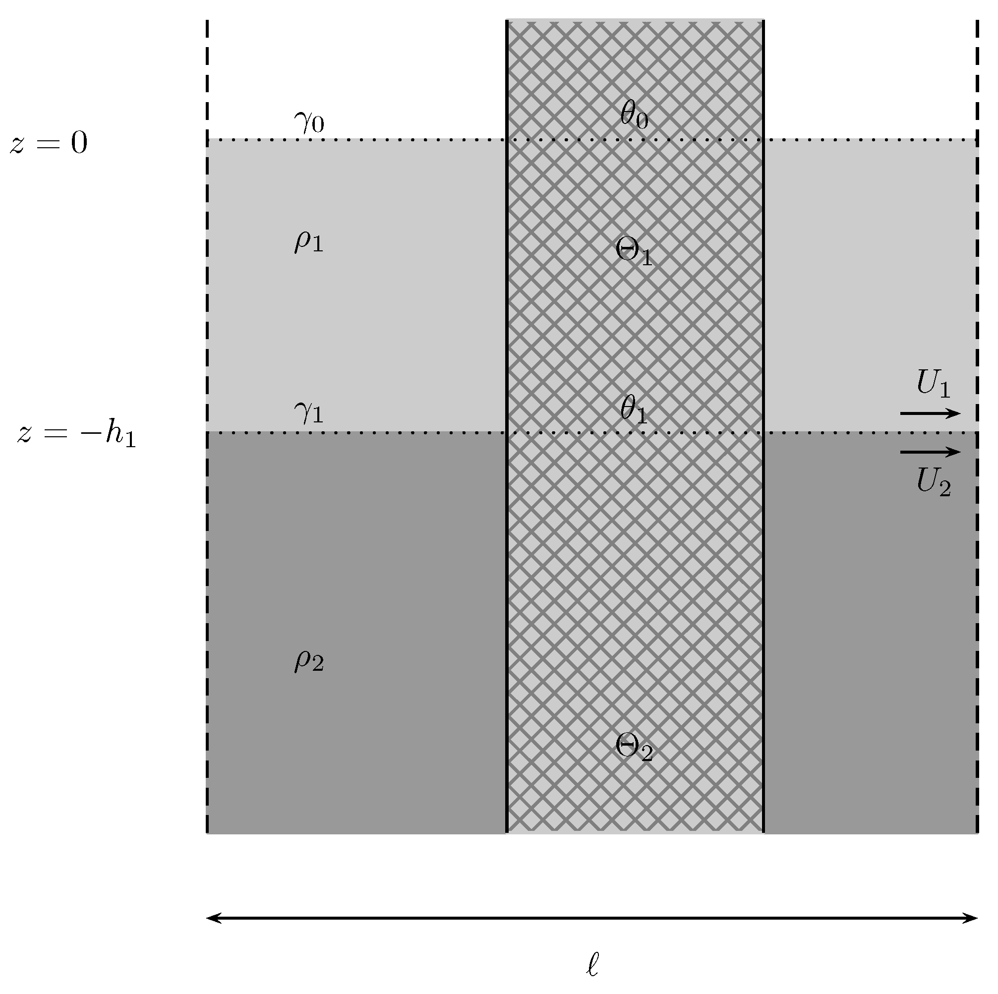
are Lipschitz domains, so that the normal vector is defined almost everywhere on ϖ 1 and ϖ 2 . We also define the surfaces (Figure 1)
σ 1 = ( x , y , z ) ϖ 1 : y ( 0 , l ) , z ( ζ ( x , y , t ) , η ( x , y , z ) ) , σ 2 = ( x , y , z ) ϖ 2 : y ( 0 , l ) , z ( , ζ ( x , y , t ) ) ,
and denote the unpierced parts of the free surface and interface by γ 0 and γ 1 , thus
γ 0 = ( x , y , z ) ϖ 1 : z = η ( x , y , t ) , γ 1 = ( x , y , z ) ϖ 1 ϖ 2 : z = ζ ( x , y , t ) .
Under the usual assumptions of the linearized water wave theory, we introduce single-valued velocity potentials in the upper and lower regions and look for trapped-mode solutions of the form
ϕ ( 1 ) ( x , y , z , t ) = Re φ T ( 1 ) ( x , y , z , t ) = Re e i ω t φ ( 1 ) ( x , y , z ) + φ B ( 1 ) ( x , y , z ) ,
ϕ ( 2 ) ( x , y , z , t ) = Re φ T ( 2 ) ( x , y , z , t ) = Re e i ω t φ ( 2 ) ( x , y , z ) + φ B ( 2 ) ( x , y , z ) .
These solutions are the sum of a time-harmonic oscillating solution, with time dependence of the form e i ω t assumed throughout, and an additional potential representing a steady background flow, which is a given of the problem. This flow is given in each cell in such a way that
φ B ( j ) ( x , y , z ) r > r 0 U j y , j = 1 , 2 ,
φ B ( j ) ( x , y , z ) r < r 0 = f B ( j ) ( x , y , z ) , j = 1 , 2 ,
where r | x | is the distance to the nearest fixed obstacle inside each cell and r 0 is a set distance relative to any obstacle boundary σ , dependent on the cell configuration and the relative size of the obstacles. The function f B ( j ) ( x , y , z ) describes the steady flow in the vicinity of the obstacles, with f B ( j ) ( x , y , z ) U j y for r = r 0 . The oscilating modes propagate along the periodic family of obstacles but decay away from them, and the l-periodicity suggests us to seek the velocity potentials in the form (cf. Wilcox [22])
φ ( j ) ( x , y + l m , z ) = e i β l m φ ( j ) ( x , y , z ) , φ B ( j ) ( x , y + l m , z ) = φ B ( j ) ( x , y , z ) , m Z , j = 1 , 2 ,
where β , the wavenumber in the direction of the line of obstacles, is assumed to be real and positive.
This is a problem of small oscillations around a steady-state motion, where we look for a velocity potential describing such waves traveling along the periodic array of fixed obstacles on top of an undisturbed steady state. Both functions, φ ( j ) ( x , y , z ) and φ B ( j ) ( x , y , z ) , j = 1 , 2 , are of potential flow. They must each independently satisfy the Laplace equation. This results in the following problem of the model periodicity cell
ρ j Δ φ ( j ) = 0 , in ϖ j , j = 1 , 2 ,
ρ j Δ φ B ( j ) = 0 , in ϖ j , j = 1 , 2 ,
ρ 1 t φ ( 1 ) t + 1 2 φ ( 1 ) + φ B ( 1 ) 2 + g η = 0 on γ 0 ,
η t = ( φ ( 1 ) + φ B ( 1 ) ) z ( φ ( 1 ) + φ B ( 1 ) ) x η x ( φ ( 1 ) + φ B ( 1 ) ) y η y on γ 0 ,
ρ 1 t φ ( 1 ) t + 1 2 φ ( 1 ) + φ B ( 1 ) 2 + g ζ = = = = = ρ 2 t φ ( 2 ) t + 1 2 φ ( 2 ) + φ B ( 2 ) 2 + g ζ on γ 1 ,
ζ t = ( φ ( j ) + φ B ( j ) ) z ( φ ( j ) + φ B ( j ) ) x ζ x ( φ ( j ) + φ B ( j ) ) y ζ y on γ 1 , j = 1 , 2 ,
ρ j φ n ( j ) = 0 , on σ j , j = 1 , 2 ,
ρ j f B ( j ) n = 0 , on σ j , j = 1 , 2 ,
φ ( j ) | y = l = e i β l φ ( j ) | y = 0 , φ y ( j ) | y = l = e i β l φ y ( j ) | y = 0 j = 1 , 2 ,
φ B ( j ) | y = l = φ B ( j ) | y = 0 , φ B ( j ) | y = l = φ B ( j ) | y = 0 j = 1 , 2 ,
where ω is the time-harmonic radian frequency, g > 0 is the acceleration due to gravity, β ( 0 , π l ] , φ y = y φ , and φ n = n φ , with n denoting the outward normal vector (pointing into the obstacles). The condition of no-flow on the surface of the obstacles (11) and (12) must be obeyed independently by the two motions. Observe that the quasi-periodicity conditions in (13) and (14) guarantee that the velocity potentials φ ( j ) satisfy the problem in the entire domain and extend smoothly from cell to cell. The conditions for the steady flow assure that it is defined universally. The momentum boundary conditions (7) and (9) stem from equating the pressures on each side of the free surface and interface, using the time derivative of the linearized Bernoulli equation in each layer (on the free surface, the atmospheric pressure is taken to be null). The kinematic conditions (10) are derived from the no-mix condition at the interface, where we impose D D t ( z ζ ( x , y , t ) ) = 0 to first-order approximation (see, e.g., Paterson [27]).

3. The Problem Without Obstacles

The problem in the absence of obstacles, where φ B ( j ) = U j y in all spaces, j = 1 , 2 can be analyzed in linearized form, such that all non-linear terms in the equations above are discarded. The boundary conditions above will be given now as
ρ 1 t φ ( 1 ) t + U 1 φ ( 1 ) y + g η = 0 at z = 0 ,
η t = φ ( 1 ) z U 1 η y at z = 0 ,
ρ 1 t φ ( 1 ) t + U 1 φ ( 1 ) y + g ζ = ρ 2 t φ ( 2 ) t + U 2 φ ( 2 ) y + g ζ at z = h 1 ,
ζ t = φ ( j ) z U j ζ y at z = h 1 , j = 1 , 2 ,
where the value is taken at the mean depth of the free surface and interface.
A solution φ T = ( φ T ( 1 ) , φ T ( 2 ) ) , with η ( x , y , t ) and ζ ( x , y , t ) , of the form
φ T ( 1 ) ( x , y , z , t ) = e i ω t φ ( 1 ) ( x , y , z ) + U 1 y = e i ω t A e i β y e ± i k 2 β 2 x e k z + B e i β y e ± i k 2 β 2 x e k z + U 1 y , φ T ( 2 ) ( x , y , z , t ) = e i ω t φ ( 2 ) ( x , y , z ) + U 2 y = e i ω t C e i β y e ± i k 2 β 2 x e k z + D e i β y e ± i k 2 β 2 x e k z + U 2 y , η ( x , y , t ) = E e i ω t e i β y e ± i k 2 β 2 , ζ ( x , y , t ) = F e i ω t e i β y e ± i k 2 β 2 , A , B , C , D , E , F C ,
solves the Laplace Equations (5) and (6), with k > 0 , β ( 0 , π l ] being the wavenumber in the y-direction, and U 1 , U 2 the layer velocities along y. The boundary conditions and the asymptotic conditions imply that D = 0 and the wavelike solutions to the linearized problem (15)–(18) without obstacles become (ignoring the fixed velocity layer terms)
φ ( 1 ) ( x , y , z ) = A e i β y e ± i k 2 β 2 x e k z + B e i β y e ± i k 2 β 2 x e k z , φ ( 2 ) ( x , y , z ) = C e i β y e ± i k 2 β 2 x e k z , η ( x , y , t ) = E e i ω t e i β y e ± i k 2 β 2 x , ζ ( x , y , t ) = F e i ω t e i β y e ± i k 2 β 2 x , A , B , C , E , F C .
The boundary conditions at the free surface and the interface yield the following dispersion relation
ω 2 sinh ( k h 1 ) ρ 2 g k ( ω β U 2 ) 2 g 2 k 2 ( ρ 2 ρ 1 ) ρ 1 ( ω β U 1 ) 4 cosh ( k h 1 ) ρ 2 ( ω β U 1 ) 2 ( ω β U 2 ) 2 g k = 0 .
This is a sixth-degree equation for ω , where ω 0 = 0 is one of the roots, with a multiplicity of two. This is a solution of no mode propagation and is discarded from our analysis. Since we want to avoid the Kelvin–Helmholtz instability (see, e.g., Kundu and Cohen [28] or Drazin [29]), the solutions have to be real. The condition for this is the combination of the following three inequalities (see also, e.g., Irving [30]),
Δ > 0 , P Δ < 0 and D Δ < 0 ,
where the discriminant Δ and the following functions are given by
Δ = 2 g k cosh ( k h 1 ) ( ( U 2 U 1 ) 8 β 8 ( 3 ρ 5 ) + 16 g 4 k 4 ( ρ 1 ) 3 ρ ( 3 ρ + 1 ) + 2 g k ( U 2 U 1 ) 6 β 6 ( 22 ρ 2 ρ + 10 ) ) o l a + 8 g 3 k 3 ( U 2 U 1 ) 2 β 2 ( 10 ρ 4 21 ρ 3 + ρ 2 + 7 ρ + 3 ) + 4 g 2 k 2 ( U 2 U 1 ) 4 β 4 ( 18 ρ 3 23 ρ 2 4 ρ 6 ) ) o g k cosh ( 3 k h 1 ) ( ( U 2 U 1 ) 8 β 8 ( 3 ρ + 5 ) + 8 g 4 k 4 ( ρ 1 ) 2 ( 2 ρ ( 3 ρ 1 ) 2 + 1 ) + 4 g k ( U 2 U 1 ) 6 β 6 ( 21 ρ 2 + 2 ρ 5 ) o l a + 4 g 2 k 2 ( U 2 U 1 ) 4 β 4 ( 44 ρ 3 59 ρ 2 12 ρ + 9 ) + 8 g 3 k 3 ( U 2 U 1 ) 2 β 2 ( 30 ρ 4 62 ρ 3 + 16 ρ 2 + 17 ρ 2 ) ) o g k cosh ( 5 k h 1 ) ( ( U 2 U 1 ) 8 β 8 ( 3 ρ + 1 ) + 4 g k ( U 2 U 1 ) 6 β 6 ( ρ 2 + ρ 1 ) + 4 g 2 k 2 ( U 2 U 1 ) 4 β 4 ( 1 ρ ) ( 8 ρ 2 5 ρ + 3 ) o l a 8 g 3 k 3 ( U 2 U 1 ) 2 β 2 ρ ( 10 ρ 3 20 ρ 2 + 14 ρ 3 ) + 8 g 4 k 4 ( 1 ρ ) ( 6 ρ 4 10 ρ 3 + 10 ρ 2 5 ρ + 1 ) ) o + 2 sinh ( k h 1 ) ( ( U 2 U 1 ) 10 β 10 ρ g k ( U 2 U 1 ) 8 β 8 ρ ( 7 ρ + 5 ) + 16 g 5 k 5 ( ρ 1 ) 3 ρ ( 5 ρ 2 1 ) o l a + 8 g 4 k 4 ( U 2 U 1 ) 2 β 2 ( ρ 1 ) ( 30 ρ 4 28 ρ 3 23 ρ 2 + 6 ρ + 1 ) + 2 g 2 k 2 ( U 2 U 1 ) 6 β 6 ( 32 ρ 3 + 14 ρ 2 + 3 ρ + 2 ) o l a + 4 g 3 k 3 ( U 2 U 1 ) 4 β 4 ( 58 ρ 4 48 ρ 3 10 ρ 2 + 8 ρ 1 ) ) o + sinh ( 3 k h 1 ) ( 3 ( U 2 U 1 ) 10 β 10 ρ 5 g k ( U 2 U 1 ) 8 β 8 ρ ( ρ + 3 ) 4 g 2 k 2 ( U 2 U 1 ) 6 β 6 ( 24 ρ 3 5 ρ 2 6 ρ 3 ) o l a 8 g 5 k 5 ( 1 ρ ) 2 ( 10 ρ 4 10 ρ 3 + 12 ρ 2 2 ρ 1 ) 4 g 3 k 3 ( U 2 U 1 ) 4 β 4 ( 62 ρ 4 72 ρ 3 + 5 ρ 2 16 ρ + 3 ) o l a 8 g 4 k 4 ( U 2 U 1 ) 2 β 2 ( 30 ρ 5 62 ρ 4 + 30 ρ 3 8 ρ 2 + 7 ρ + 2 ) ) o + sinh ( 5 k h 1 ) ( ( U 2 U 1 ) 10 β 10 ρ + g k ( U 2 U 1 ) 8 β 8 ρ ( 9 ρ 5 ) + 4 g 3 k 3 ( U 2 U 1 ) 4 β 4 ( ρ 1 ) ( 14 ρ 3 10 ρ 2 + ρ + 1 ) o l a + 4 g 2 k 2 ( U 2 U 1 ) 6 β 6 ( 8 ρ 3 9 ρ 2 + 3 ρ + 1 ) + 8 g 4 k 4 ( U 2 U 1 ) 2 β 2 ρ ( 6 ρ 4 14 ρ 3 + 16 ρ 2 10 ρ + 3 ) o l a 8 g 5 k 5 ( 1 ρ ) ( 2 ρ 5 4 ρ 4 + 10 ρ 3 10 ρ 2 + 5 ρ 1 ) ) , P Δ = 4 ( sinh ( 2 k h 1 ) + cosh ( 2 k h 1 ) ) 2 β 2 ( U 2 U 1 ) 2 4 g k ( ρ 1 ) o l a + ( sinh ( 4 k h 1 ) + cosh ( 4 k h 1 ) ) 4 g k ( ρ + 1 ) β 2 ( 2 ρ 1 ) ( U 2 U 1 ) 2 + β 2 ( 2 ρ + 1 ) ( U 2 U 1 ) 2 , and D Δ = 64 β 4 ρ ( U 2 U 1 ) 4 ( sinh ( 4 k h 1 ) + cosh ( 4 k h 1 ) ) ρ sinh 2 ( 2 k h 1 ) 8 sinh ( k h 1 ) cosh 3 ( k h 1 ) o l + 4 g 2 k 2 ( sinh ( k h 1 ) + cosh ( k h 1 ) ) ( ρ sinh ( k h 1 ) + cosh ( k h 1 ) ) 2 ( sinh ( 3 k h 1 ) + cosh ( 3 k h 1 ) ) ( cosh ( k h 1 ) + ( 2 ρ 1 ) sinh ( k h 1 ) ) 2 o l + 2 β 2 g k ( U 2 U 1 ) 2 ( sinh ( h 1 k ) + cosh ( h 1 k ) ) ( ρ sinh ( k h 1 ) + cosh ( k h 1 ) ) ( 3 ρ 2 + 1 ) ( sinh ( 2 k h 1 ) + cosh ( 2 k h 1 ) ) o l ( 3 ρ 2 + ρ 2 ) ( sinh ( 4 k h 1 ) + cosh ( 4 k h 1 ) ) + ( ρ 2 + 1 ) ( sinh ( 6 k h 1 ) + cosh ( 6 k h 1 ) ) ρ 2 + ρ .
The discriminant is the more stringent of the three inequalities, which have to be met simultaneously. All three quantities are functions of ( U 2 U 1 ) 2 . This condition of the discriminant also implies that the four real solutions are different, each with a multiplicity of one. One could allow for real solutions with higher multiplicity, but that would imply that Δ = 0 , which defines a line boundary in the ( U 1 , U 2 ) velocity domain. Those solutions represent borderline situations that separate the domain with only real solutions from the domain with complex solutions. Complex solutions represent exponential instability in the velocity potential solutions, leaving the domain of applicability of the equations. We focus thus on real solutions of a multiplicity of one. They are ordered according to ω 1 < < ω 4 .
If we add the same general speed U 0 to U j , j = 1 , 2 , we find that
ω i / β ω i / β + U 0 , Δ Δ , P Δ P Δ , D Δ D Δ , when ( U 1 , U 2 ) ( U 1 + U 0 , U 2 + U 0 ) , i = 1 , , 4 .
The smallest solution (in modulus) of the four is a relative concept. The addition of U 0 to both speeds is the same as moving on velocity space from a chosen initial point along the line U 2 = U 1 + b . This line has a slope of one and b is a real constant, the value of U 2 is obtained when that line crosses the U 2 axis. Adding U 0 performs one of two things: (a) changing the referential of the observer or (b) adding global speed to the layers relative to a chosen referential. Later, we will see that the preferred referential is that of the fixed obstacles. Along any line with a unitary slope contained in the stability domain given by Δ > 0 , it will thus happen that, depending on its distance from the origin, each solution is the closest to zero in different intervals along that line. From the third quadrant to the first, the smallest value (in modulus) of ω i will thus be ω 4 ω 3 ω 2 ω 1 .
There is an additional property of the solutions. If one makes ( U 1 , U 2 ) ( U 1 , U 2 ) , one finds that
ω 1 ( U 1 , U 2 ) = ω 4 ( U 1 , U 2 ) and ω 2 ( U 1 , U 2 ) = ω 3 ( U 1 , U 2 ) .
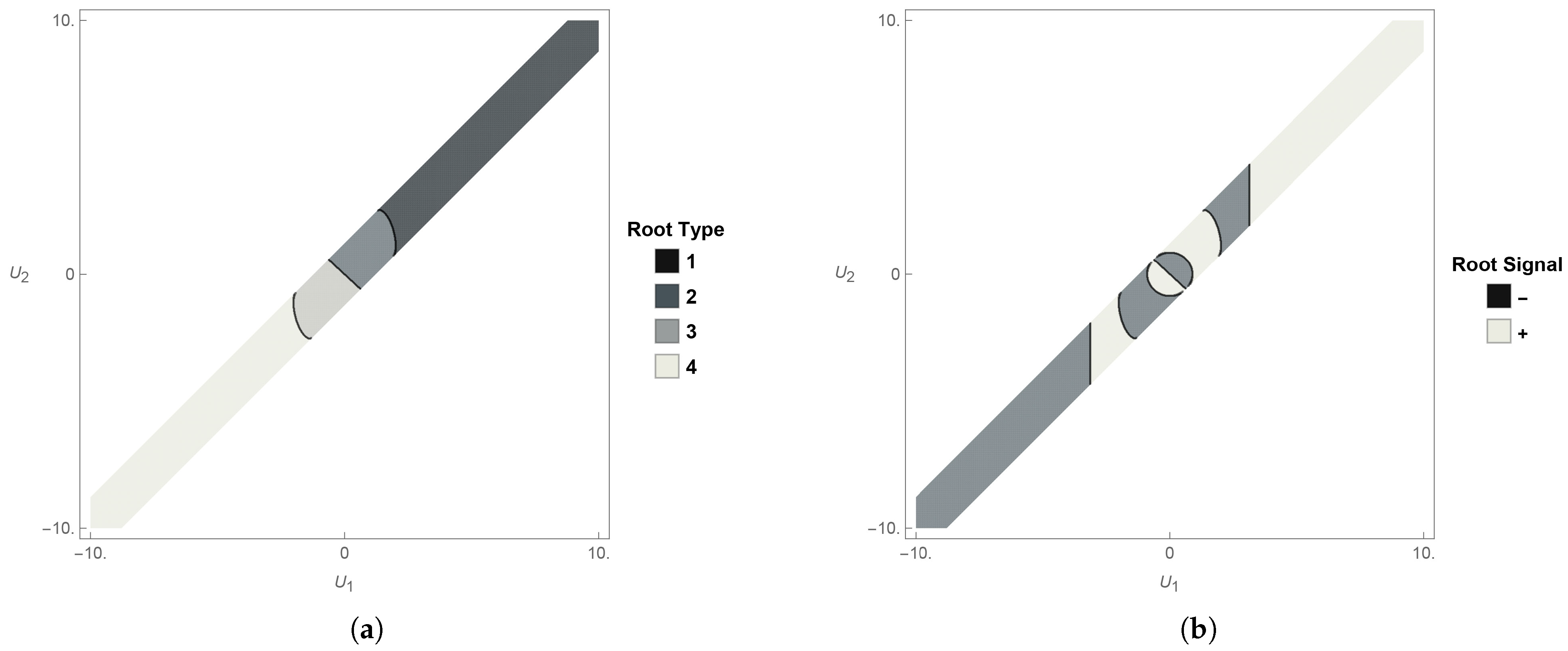
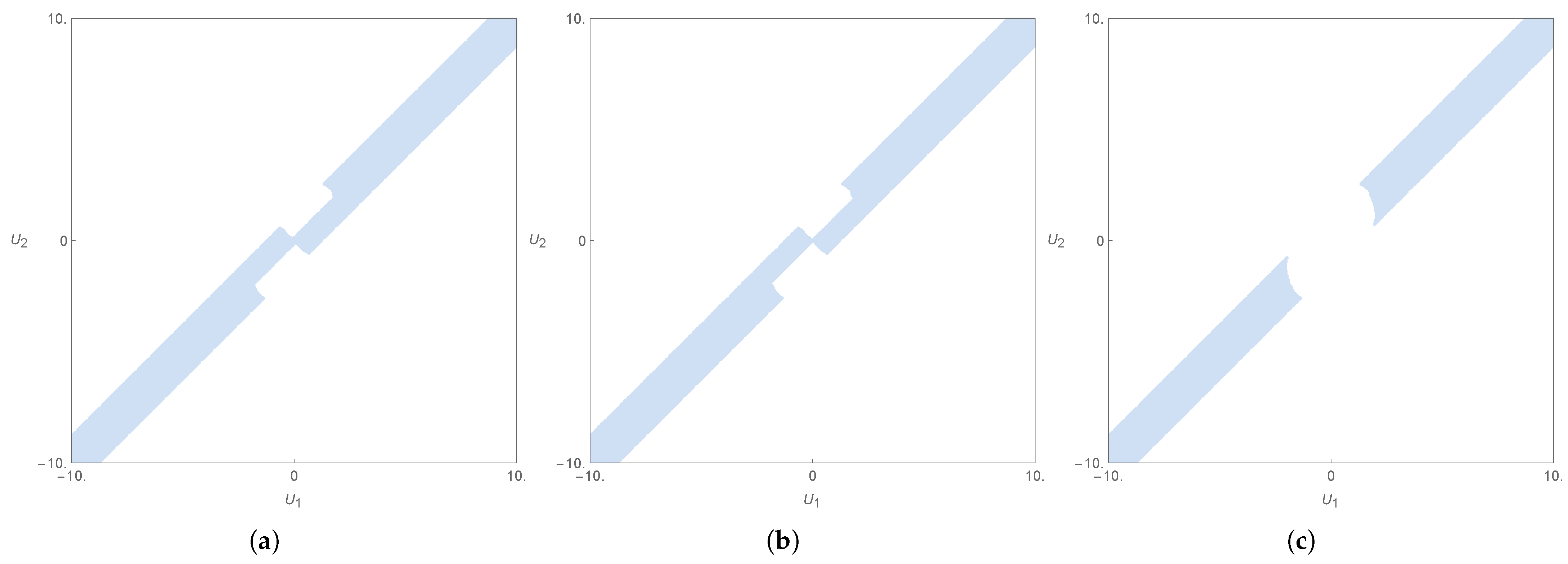
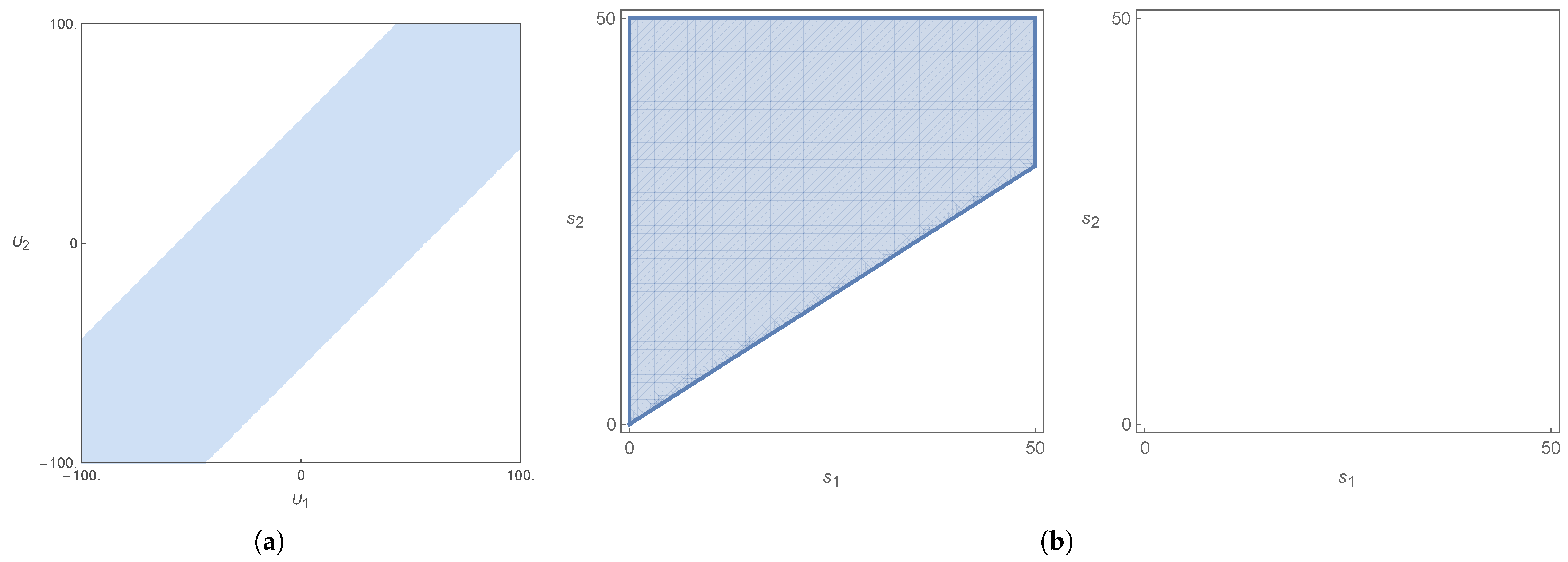
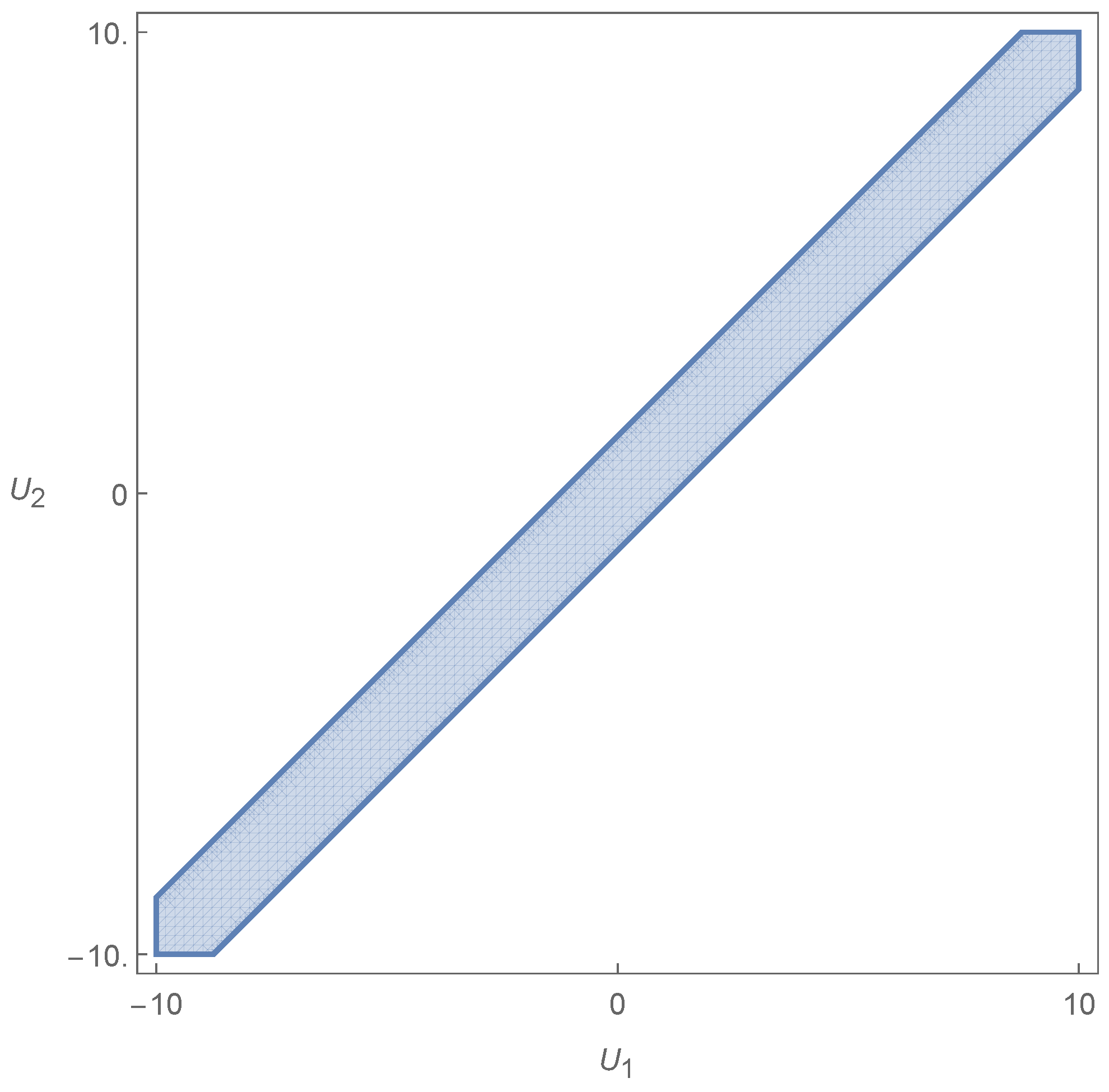
In Figure 2b, one can see that the border line between the region where ω 2 and ω 3 are the closest to zero is a straight line passing through the origin. The above symmetry allows us to effectively choose only one half-plane to solve the entire problem. Since we can work only in half of the entire velocity space, we choose the top-right half, encompassing the first quadrant. The closest solutions to zero will then be ω 2 and ω 1 , respectively. In each respective domain, that solution is the one whose value | ω i | is the smallest of the four. This solution, evaluated as k = β , is then defined, for that domain, as ω , with ω = ω i ( k = β ) , for i = 1 , 2 (see Figure 3).
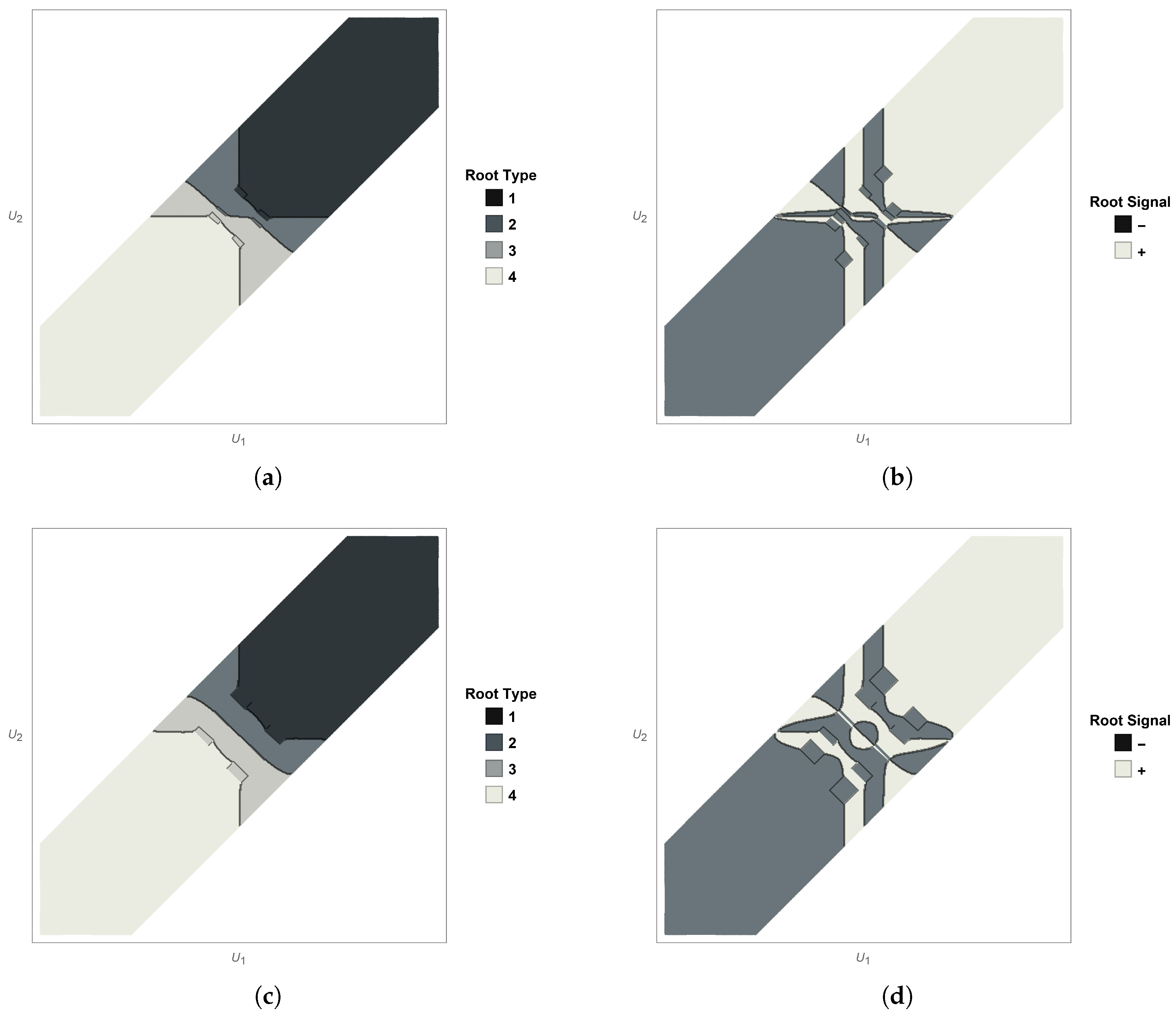
Given the nature of the expressions for Δ , P Δ , and D Δ , it is not possible to abstract the general behavior of the stability region with the change in the general parameters of the free problem ( h 1 and ρ = ρ 1 / ρ 2 ). The plots in Figure 4 show us the general trend of the stability region when ρ is changed for fixed h 1 .
It is clear that the region is reduced by the increase in the density ratio, ρ = ρ 1 / ρ 2 . There is, moreover, a simplification of the root and signal pattern with increasing ρ .
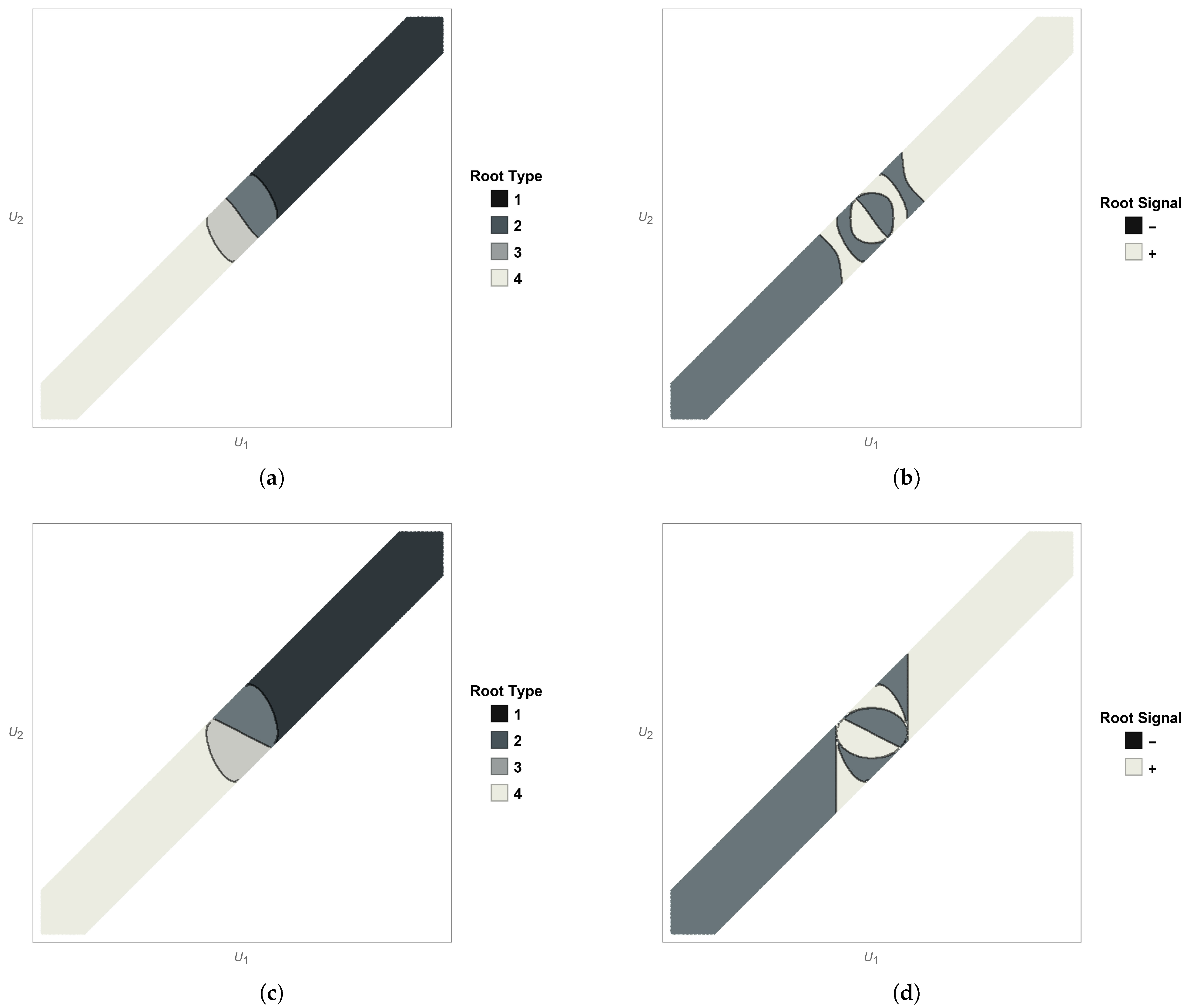
Changing gears, we now show the evolution of the stability condition when h 1 is changed for fixed ρ .
It became prominent from the plots in Figure 5 that the influence of h 1 is not as stark as the influence of ρ . However, unlike with ρ in Figure 4, the increase in h 1 is beneficial to stability. It seems, however, to diminish as the layer thickness increases (the evolution h 1 = 250 h 1 = 1000 is almost imperceptible).
In Figure 6, we can see that the increase in β (and k concomitantly) works against stability. In the case depicted, it was from β = π / 100 (see Figure 4a,b) to β = 1 (in Figure 6). The region is leaner and the domain where ω 2 and ω 3 are the solutions for ω is strongly reduced. Also, in Figure 6b, it can be seen that the pattern for the sign of each respective ω i , i = 1 , , 4 , is miniaturized.
All in all, we can conclude that layer thickness is a stability provider, whereas a higher density ratio is not, since a pair of layers with similar densities constitute a much less stable configuration than two layers with very dissimilar densities (as long as gravitic stability is assumed ρ 1 < ρ 2 ). Also, the wavenumber of the incoming wave β works against stability, since the region was drastically reduced when β = π / 100 1 . It means that shorter waves help destabilize the two-layer configuration. The symmetry with respect to the origin, ( U 1 , U 2 ) ( U 1 , U 2 ) , is preserved, as was to be expected, given the physical attributes of the system.
The spectral parameter will be Λ = ω 2 / g . This means that, defining Λ i = ω i 2 / g ,
Λ 1 ( U 1 , U 2 ) = Λ 4 ( U 1 , U 2 ) and Λ 2 ( U 1 , U 2 ) = Λ 3 ( U 1 , U 2 ) .
Working in the half-plane chosen, we have
Λ 3 ( U 1 , U 2 ) = Λ ( U 1 , U 2 ) and Λ 4 ( U 1 , U 2 ) = Λ ( U 1 , U 2 ) ,
in the respective domain, where ω 3 and ω 4 are ω . The non-trivial solution corresponding to Λ = ω 2 / g is up to multiplication by an arbitrary non-zero complex constant,
ϕ ( 1 ) ( y , z ) = e i β y Φ ( 1 ) ( z ) , ϕ ( 2 ) ( y , z ) = e i β y Φ ( 2 ) ( z ) ,
where
Φ ( 1 ) ( z ) = A e β z + B e β z , Φ ( 2 ) ( z ) = C e β z ,
η ( y , t ) = E e i ( ω t β y ) , ζ ( y , t ) = F e i ( ω t β y ) .
The coefficients are equal to
A = ( ω β U 1 ) β g + ( ω β U 1 ) 2 ,
B = ( ω β U 1 ) β g ( ω β U 1 ) 2 ,
C = 2 e β h 1 ( ω β U 2 ) cosh ( β h 1 ) ( ω β U 1 ) 2 β g sinh ( β h 1 ) ,
E = 2 i β ( ω U 1 β ) 2 ,
F = 2 i β cosh ( β h 1 ) ( ω β U 1 ) 2 β g sinh ( β h 1 ) .
Note that the terms of the form ( ω β U i ) are invariant under ( U 1 , U 2 ) ( U 1 + U 0 , U 2 + U 0 ) .

4. The Equations in the Limit of r 0 0 +

To streamline the analysis for configurations involving obstacles, we assume that the uniform velocities in both the upper and lower are such that the boundary layer thickness r 0 approaches a negligent value. Consequently, the region surrounding the obstacles, wherein the velocity potential takes the form f B ( j ) ( x , y , z ) (see (4)), shrinks to a negligible volume. Henceforth, we adopt the limiting case r 0 0 + . In broader terms,
φ B ( j ) z 0 , ( no vertical flow )
φ B ( j ) x U j , ( negligible lateral flow )
φ B ( j ) y U j , r > r 0 0 + . ( overall flow in y - direction )
We will thus discard terms such as x φ B x ζ , but not terms such as U j y ζ . Assuming the general format of the solutions in (19) and rewriting the equations of motion with the above approximations, we obtain the first term of the Taylor expansion for the linearized Bernoulli equation at the free surface and at the interface (see [27])
ρ 1 ω 2 g φ ( 1 ) + ω β g φ ( 1 ) U 1 + η t | z = 0 = 0 ,
ρ 1 ω 2 g φ ( 1 ) + ω β g φ ( 1 ) U 1 + ζ t = ρ 2 ω 2 g φ ( 2 ) + ω β g φ ( 2 ) U 2 + ζ t | z = h 1 .
The linear surface and interface kinematic conditions for both potentials stem from the material derivative (to first order in Taylor about z = h 1 ). Thus,
D D t z ζ = ζ t + w u ζ x v ζ y U ζ y = 0 .
Using
( u , v , w ) = φ x , φ y , φ z
we obtain the kinematic conditions (about z = h 1 ) as
φ ( 1 ) z ζ t + U 1 ζ y ,
φ ( 2 ) z ζ t + U 2 ζ y .
The same applies to the free surface (about z = 0 ), with η instead of ζ ,
φ ( 1 ) z η t + U 1 η y .
Using the ansätze in (19), we see that, for the interface,
ζ = i ω β U 1 φ ( 1 ) z = i ω 1 U 1 c φ ( 1 ) z ,
ζ = i ω β U 2 φ ( 2 ) z = i ω 1 U 2 c φ ( 2 ) z ,
where c = ω / β . From (42) and (43), we obtain the following boundary condition
1 1 U 1 c φ ( 1 ) z = 1 1 U 2 c φ ( 2 ) z .
If we make the following renaming
δ j = 1 U j c , φ j = φ ( j ) δ j , j = 1 , 2
where the δ j are Doppler factors, we arrive at
φ 1 z = φ 2 z .
The equations for the interface can then be reduced to the following two, neglecting the interface function ζ = ζ ( y , t ) ,
ρ 1 Λ δ 1 2 φ 1 + φ 1 z = ρ 2 Λ δ 2 2 φ 2 + φ 2 z | z = h 1 ,
φ 1 z = φ 2 z | z = h 1 .
In the same way, on the free surface, we find
ρ 1 Λ δ 1 2 φ 1 + φ 1 z | z = 0 = 0 ,
where we can ignore the free surface function η = η ( y , t ) . The remainder equations can be directly applied to the primed potentials.
Remark 1.
If δ j = 0 , one of the layers has velocity equal to the mode velocity. This turns out to be a degenerate case, which is equivalent to making ω β U 1 = 0 (resp. ω β U 2 = 0 ). The equations at the interface become, when ω β U 1 = 0 ,
φ ( 1 ) z = 0 | z = h 1 , φ ( 2 ) z = i ω β U 2 ζ | z = h 1
and
Λ 1 β U 2 ω 2 φ ( 2 ) ρ 2 ρ 1 ρ 2 φ ( 2 ) z = 0 | z = h 1 .
On the free surface, the equation becomes
η = 0 .
This serves to show that there is no mode at the free surface. Equation (51) is analogous to that of the free-surface, with Λ Λ 1 β U 2 / ω 2 . If we make ρ 1 0 , we have the same equation, which is obtained for the free surface by assuming that the air density is zero, ρ 0 = 0 . If we perform the same on the second layer ( ω β U 2 = 0 ), we obtain the following for the free surface
Λ 1 β U 1 ω 2 φ ( 1 ) φ ( 1 ) z = 0 | z = 0
and the interface
φ ( 1 ) z = i ω β U 1 ζ | z = 0 , φ ( 2 ) z = 0 | z = h 1 ,
Λ 1 β U 1 ω 2 φ ( 1 ) + ρ 2 ρ 1 ρ 1 φ ( 1 ) z = 0 | z = h 1 .
This is not equivalent to the form of a free surface momentum equation and the analogy breaks, unless ρ 2 0 . However, in this case, the gravitational stability condition ρ 2 > ρ 1 is not respected. We assume thus throughout that δ j 0 for j = 1 , 2 . At the end, despite everything, the variational formulation can be extended continuously to the case of δ j = 0 , j = 1 , 2 .

5. Variational and Operator Formulation

We now multiply the equations in (5) by a test function ψ ( 1 ) C c ( ϖ 1 ¯ ) and the Equation (6) by another test function ψ ( 2 ) C c ( ϖ 2 ¯ ) , where C c ( ϖ j ¯ ) is the space of infinitely differentiable functions with compact support in ϖ j ¯ , j = 1 , 2 , satisfying the Dirichlet quasi-periodicity condition, which is the first equation in (13). We then integrate the sum of both equations (in each layer) in the fluid domain and add the contributions of the two layers.
The domain enveloping the obstacles and contained within the r 0 distance around each obstacle is denoted by ϖ r 0 , j ϖ j and is limited by the boundaries σ j , σ r 0 , j , and γ r 0 , ( j 1 ) γ j 1 (where appropriate), where σ r 0 , j is an artificial boundary at r = r 0 ; here, the functions cross smoothly from one domain to the next. The above sum is
j = 1 2 ρ j ϖ r 0 , j Δ φ ( j ) + f B ( j ) ψ ( j ) ¯ d V + ρ j ϖ j ϖ r 0 , j Δ φ ( j ) + U j y ψ ( j ) ¯ d V = 0 .
After integrating by parts, this sum becomes
ρ 1 γ r 0 , 0 ( φ ( 1 ) + f B ( 1 ) ) · n ψ ( 1 ) ¯ d S + ρ 1 γ 0 γ r 0 , 0 ( φ ( 1 ) + U 1 y ) · n ψ ( 1 ) ¯ d S + j = 1 2 ρ j γ r 0 , 1 ( φ ( j ) + f B ( j ) ) · n ψ ( j ) ¯ d S + ρ j γ 1 γ r 0 , 1 ( φ ( j ) + U j y ) · n ψ ( j ) ¯ d S ρ j ϖ r 0 , j ( φ ( j ) + f B ( j ) ) · ψ ( j ) ¯ d V ρ j ϖ j ϖ r 0 , j ( φ ( j ) + U j y ) · ψ ( j ) ¯ d V = 0 .
We have used the boundary conditions in (11) and (12), plus the natural continuity across the artificial boundary σ r 0 , which cancels the contributions on this boundary.
Working now within the approximation presented in the previous section, such that r 0 0 + , we can discard the first, third, and fifth integrals in (57) and approximate the result by
ρ 1 γ 0 ( φ ( 1 ) + U 1 y ) · n ψ ( 1 ) ¯ d S + j = 1 2 ρ j γ 1 ( φ ( j ) + U j y ) · n ψ ( j ) ¯ d S ρ j ϖ j ( φ ( j ) + U j y ) · ψ ( j ) ¯ d V = 0 .
Ignoring quadratic terms, the normal defined on the free surface is upward pointing and the normal defined on the interface is downward pointing from the standpoint of the first layer and the opposite from that of the second, that is
n 0 0 , η / y , 1 , n 1 0 , ζ / y , 1 , n 2 0 , ζ / y , 1 .
Using Equation (41), we obtain for the free surface
φ ( 1 ) + U 1 y · n 0 φ 1 z ,
and using Equations (39) and (40), we obtain for the interface
φ ( 1 ) + U 1 y · n 1 φ 1 z ,
φ ( 2 ) + U 2 y · n 2 φ 2 z .
From the boundary conditions (47)–(49), we draw
φ 1 z = Λ δ 1 2 φ 1 | z = 0 ,
φ 1 z = Λ ρ 1 ρ 2 ρ 1 δ 1 2 φ 1 ρ 2 δ 2 2 φ 2 | z = h 1 ,
so in the end, we obtain, for the whole configuration with both layers, the following variational formulation
ρ 1 ϖ 1 ( φ ( 1 ) + U 1 y ) · ψ ( 1 ) ¯ d V + ρ 2 ϖ 2 ( φ ( 2 ) + U 2 y ) · ψ ( 2 ) ¯ d V = = ρ 1 γ 0 Λ δ 1 2 φ 1 ψ ( 1 ) ¯ d S + γ 1 Λ ρ 2 ρ 1 ρ 2 δ 2 2 φ 2 ρ 1 δ 1 2 φ 1 ρ 2 ψ ( 2 ) ρ 1 ψ ( 1 ) ¯ d S .
From another angle, we note that (to first order)
φ 1 · n φ 1 x , φ 1 y , φ 1 z · 0 , η y , 1 = φ 1 y η y + φ 1 z φ 1 z ,
φ 1 · n φ 1 x , φ 1 y , φ 1 z · 0 , ζ y , 1 = φ 1 y ζ y φ 1 z φ 1 z ,
φ 2 · n φ 2 x , φ 2 y , φ 2 z · 0 , ζ y , 1 = φ 2 y ζ y + φ 2 z φ 2 z .
This means that we can rewrite the variational formulation in (65) as the primed potential variational formulation
ρ 1 ϖ 1 φ 1 · ψ ( 1 ) ¯ d V + ρ 2 ϖ 2 φ 2 · ψ ( 2 ) ¯ d V = = ρ 1 γ 0 Λ δ 1 2 φ 1 ψ ( 1 ) ¯ d S + γ 1 Λ ρ 2 ρ 1 ρ 2 δ 2 2 φ 2 ρ 1 δ 1 2 φ 1 ρ 2 ψ ( 2 ) ρ 1 ψ ( 1 ) ¯ d S .
The term originated by the background flow potential is a given of the problem and not a variable. The background kinetic energy is not relevant to the variational formulation, since it is fixed. The trapped-mode problem is about the energy of the oscillating mode, which is added to the steady background flow. The variation in energy (not its full content), is what is relevant, in much the same way as the gravitational potential energy is always determined up to a constant. It is the difference in potential energy, and not its absolute value, that is relevant (within the bounds of the linear approximation). It is therefore natural to expect that the two approaches, (65) and (69), are equivalent (within the confines of the approximation).
The expression in (69) is not symmetrical under ψ ( j ) φ ( j ) . By changing the test function
ψ j = ψ ( j ) δ j , j = 1 , 2 ,
we obtain
ρ 1 ϖ 1 φ 1 · δ 1 2 ψ 1 ¯ d V + ρ 2 ϖ 2 φ 2 · δ 2 2 ψ 2 ¯ d V = = ρ 1 γ 0 Λ δ 1 2 φ 1 δ 1 2 ψ 1 ¯ d S + γ 1 Λ ρ 2 ρ 1 ρ 2 δ 2 2 φ 2 ρ 1 δ 1 2 φ 1 ρ 2 δ 2 2 ψ 2 ρ 1 δ 1 2 ψ 1 ¯ d S .
We can see that the right-hand side becomes symmetric. By eliminating the redundant primed terms
ρ 1 ϖ 1 φ ( 1 ) · ψ ( 1 ) ¯ d V + ρ 2 ϖ 2 φ ( 2 ) · ψ ( 2 ) ¯ d V = = ρ 1 γ 0 Λ δ 1 2 φ 1 ψ ( 1 ) ¯ d S + γ 1 Λ ρ 2 ρ 1 ρ 2 δ 2 φ ( 2 ) ρ 1 δ 1 φ ( 1 ) ρ 2 δ 2 ψ ( 2 ) ρ 1 δ 1 ψ ( 1 ) ¯ d S ,
we arrive at the variational formulation of our problem.
Let H β ( ϖ j ) , j = 1 , 2 be a subspace of H 1 ( ϖ j ) , satisfying the Dirichlet quasi-periodicity condition, i.e.,
H β ( ϖ j ) = ψ H 1 ( ϖ j ) : ψ | y = l = e i β l ψ | y = 0 , j = 1 , 2 ,
and let ( · , · ) ϖ j and ( · , · ) γ 0 , 1 denote the scalar products in the Lebesgue spaces L 2 ( ϖ j ) and L 2 ( γ 0 , 1 ) , respectively. Morever, let H β be the function space of elements φ = ( φ ( 1 ) , φ ( 2 ) ) H β ( ϖ 1 ) × H β ( ϖ 2 ) , equipped with the scalar product
φ , ψ = ρ 1 φ ( 1 ) , ψ ( 1 ) ϖ 1 + ρ 2 φ ( 2 ) , ψ ( 2 ) ϖ 2 , φ , ψ H β .
Note that the quasi-periodicity condition excludes non-zero constants from belonging to H β ( ϖ j ) , j = 1 , 2 . The variational formulation of (5)–(14) consists of (cf. [31]) finding a non-trivial φ = ( φ ( 1 ) , φ ( 2 ) ) H β and Λ C , such that for all ψ = ( ψ ( 1 ) , ψ ( 2 ) ) H β
ρ 1 φ ( 1 ) , ψ ( 1 ) ϖ 1 + ρ 2 φ ( 2 ) , ψ ( 2 ) ϖ 2 = Λ ρ 1 δ 1 φ ( 1 ) , δ 1 ψ ( 1 ) γ 0 + Λ ρ 2 ρ 1 ρ 2 δ 2 φ ( 2 ) ρ 1 δ 1 φ ( 1 ) , ρ 2 δ 2 ψ ( 2 ) ρ 1 δ 1 ψ ( 1 ) γ 1 .
It is obvious that we cannot define a linear spectral problem when the parameter is Λ = ω 2 / g , if at the same time, there is ω in the definition of δ j . In this situation, an approximation is warranted, if the formalism is to be of use. The method followed (see, e.g., Nazarov and Videman [14]) is to perturb the solution φ on the threshold of k = β , and from the compact perturbation, to obtain a relation that is sufficient to guarantee that the discreet spectrum of the spectral problem derived from the initial equations is non-empty. This means that the relevant functions in the appropriate functional space are all close to ϕ , in other words, that their associated mode speed is close to c . This suggests the approximation δ j γ j and c c . Consequently, from now on, the γ are all γ and the speed in the Doppler factors is c . In the same vein, all the function spaces below are assumed to be subsets of the designated spaces of functions, with mode speeds in the neighborhood of the mode speed of ϕ .
We now introduce a trace-interface operator T : H β H β
T φ , ψ = ρ 1 δ 1 φ ( 1 ) , δ 1 ψ ( 1 ) γ 0 + 1 ρ 2 ρ 1 ρ 2 δ 2 φ ( 2 ) ρ 1 δ 2 φ ( 1 ) , ρ 2 δ 2 ψ ( 2 ) ρ 1 δ 1 ψ ( 1 ) γ 1 , φ , ψ H β .
The operator T is continuous thanks to the trace inequality (cf. Evans and Gariepy [32])
φ ( j ) L 2 ( ϖ j ) c φ ( j ) H 1 ( ϖ j ) , j = 1 , 2 .
The spectral problem (5)–(13) can now be written as
T φ = μ φ ,
where μ = Λ 1 is a new spectral parameter. The continuous spectrum of T, σ c ( T ) , is determined by the continuous spectrum of the original free problem (5)–(13). The latter lies on [ Λ , ) and thus σ c ( T ) = { μ : μ ( 0 , μ ] } , with μ = ( Λ ) 1 . Given that μ = 0 is an eigenvalue of infinite multiplicity with the associated eigenspace
H β 0 = φ H β : φ ( 1 ) = 0 on γ 0 , ρ 1 δ 1 φ ( 1 ) = ρ 2 δ 2 φ ( 2 ) on γ 1 ,
the essential spectrum of T is σ e ( T ) = { μ : μ [ 0 , μ ] } .
The operator T is positive, continuous, and symmetric. It is thus self-adjoint (note that δ j 0 are assumed). Its spectrum σ ( T ) = σ e ( T ) σ d ( T ) lies on the interval [ 0 , τ ] of the real axis in the complex plane, with τ being the operator norm of T and σ d ( T ) , its discrete spectrum. For the discrete spectrum, we have two possibilities: either the norm of the operator T is equal to μ and τ = μ , so that the discrete spectrum is empty, or τ > μ , and the discrete spectrum is non-empty, since τ σ ( T ) (cf. Birman and Solomjak [33], Theorem 10.2.1).

6. A Sufficient Condition for the Existence of a Trapped Mode ( β > 0 )

The definition of an operator norm is
τ = sup φ H β { 0 } T φ , φ φ , φ = sup φ H β { 0 } ρ 1 δ 1 φ ( 1 ) L 2 ( γ 0 ) 2 + 1 ρ 2 ρ 1 ρ 2 δ 2 φ ( 2 ) ρ 1 δ 1 φ ( 1 ) L 2 ( γ 1 ) 2 ρ 1 φ ( 1 ) L 2 ( ϖ 1 ) 2 + ρ 2 φ ( 2 ) L 2 ( ϖ 2 ) 2
Consider now a function φ ϵ = ( φ ϵ ( 1 ) , φ ϵ ( 2 ) ) defined by φ ϵ ( 1 ) ( x , y , z ) = e ϵ | x | ϕ ( 1 ) ( y , z ) and φ ϵ ( 2 ) ( x , y , z ) = e ϵ | x | ϕ ( 2 ) ( y , z ) , where ϕ = ( ϕ ( 1 ) , ϕ ( 2 ) ) is the solution associated with the cut-off value Λ , cf. (25)–(27), and ϵ 1 is a small positive parameter. It is easy to see that φ ϵ H β , so that we can estimate the right-hand side in (75) from below using φ ϵ as a trial function.
If θ 0 , 1 is the part of the surface Γ 0 , 1 pierced by the obstacles, i.e.,
θ 0 = ( x , y , z ) Θ 1 ¯ : z = 0 and θ 1 = ( x , y , z ) Θ 1 ¯ Θ 2 ¯ : z = h 1 ,
then we obtain
T φ ϵ , φ ϵ = ρ 1 δ 1 φ ϵ ( 1 ) L 2 ( γ 0 ) 2 + 1 ρ 2 ρ 1 ρ 2 δ 2 φ ϵ ( 2 ) ρ 1 δ 1 φ ϵ ( 1 ) L 2 ( γ 1 ) 2 = ρ δ 1 φ ϵ ( 1 ) L 2 ( Γ 0 ) 2 ρ δ 1 φ ϵ ( 1 ) L 2 ( θ 0 ) 2 o l a + 1 ρ 2 ρ 1 ρ 2 δ 2 φ ϵ ( 2 ) ρ 1 δ 1 φ ϵ ( 1 ) L 2 ( Γ 1 ) 2 1 ρ 2 ρ 1 ρ 2 δ 2 φ ϵ ( 2 ) ρ 1 δ 1 φ ϵ ( 1 ) L 2 ( θ 1 ) 2 = ϵ 1 ρ 1 l δ 1 Φ ( 1 ) ( 0 ) 2 + l ρ 2 ρ 1 ρ 2 δ 2 Φ ( 2 ) ( h 1 ) ρ 1 δ 1 Φ ( 1 ) ( h 1 ) 2 ρ 1 δ 1 Φ ( 1 ) ( 0 ) 2 meas ( θ 0 ) 1 ρ 2 ρ 2 ρ 2 δ 2 Φ ( 2 ) ( h 1 ) ρ 1 δ 1 Φ ( 1 ) ( h 1 ) 2 meas ( θ 1 ) + O ( ϵ ) ,
where we have used the approximation e 2 ϵ | x | = 1 + O ( ϵ ) in the compact sets θ 0 , 1 ¯ .
In the same way, we obtain
φ ϵ , φ ϵ = ρ 1 φ ϵ ( 1 ) L 2 ( ϖ 1 ) 2 + ρ 2 φ ϵ ( 2 ) L 2 ( ϖ 2 ) 2 = ρ 1 φ ϵ ( 1 ) L 2 ( Π 1 ) 2 ρ 1 φ ϵ ( 1 ) L 2 ( Θ 1 ) 2 + ρ 2 φ ϵ ( 2 ) L 2 ( Π 2 ) 2 ρ 2 φ ϵ ( 2 ) L 2 ( Θ 2 ) 2 = ϵ 1 ρ 1 l Φ ( 1 ) ( 0 ) Φ z ( 1 ) ( 0 ) ρ 1 l Φ ( 1 ) ( h 1 ) Φ z ( 1 ) ( h 1 ) + ϵ 1 ρ 2 l Φ ( 2 ) ( h 1 ) Φ z ( 2 ) ( h 1 ) ρ 1 Θ 1 | Φ z ( 1 ) ( z ) | 2 + β 2 | Φ ( 1 ) ( z ) | 2 d x d y d z ρ 2 Θ 2 | Φ z ( 2 ) ( z ) | 2 + β 2 | Φ ( 2 ) ( z ) | 2 d x d y d z + O ( ϵ ) ,
where we have used integration by parts and observed that ϕ is a solution to the problem (5)–(13) without obstacles, and thus
Δ ϕ ( j ) = e i β y d 2 d z 2 Φ ( j ) ( z ) β 2 Φ ( j ) ( z ) = 0 , j = 1 , 2 .
On the other hand, by making use of the boundary conditions (7)–(12) for Φ = ( Φ ( 1 ) , Φ ( 2 ) ) ,
Φ z ( 1 ) ( 0 ) = Λ δ 1 2 Φ ( 1 ) ( 0 ) , δ 2 Φ z ( 1 ) ( h 1 ) = δ 1 Φ z ( 2 ) ( h 1 ) ,
ρ 1 Φ z ( 1 ) ( h 1 ) Λ δ 1 2 Φ ( 1 ) ( h 1 ) = ρ 2 Φ z ( 2 ) ( h 1 ) Λ δ 2 2 Φ ( 2 ) ( h 1 ) ,
we write
Φ z ( 1 ) ( 0 ) = Λ δ 1 2 Φ ( 1 ) ( 0 ) ,
Φ z ( 1 ) ( h 1 ) = δ 1 Λ ρ 2 ρ 1 ρ 2 δ 2 Φ ( 2 ) ( h 1 ) ρ 1 δ 1 Φ ( 1 ) ( h 1 ) .
This allows us to conclude that
φ ϵ , φ ϵ = ϵ 1 Λ ρ 1 l δ 1 Φ ( 1 ) ( 0 ) 2 + l ρ 2 ρ 1 ρ 2 δ 2 Φ ( 2 ) ( h 1 ) ρ 1 δ 1 Φ ( 1 ) ( h 1 ) 2 ρ Θ 1 | Φ z ( 1 ) ( z ) | 2 + β 2 | Φ ( 1 ) ( z ) | 2 d x d y d z Θ 2 | Φ z ( 2 ) ( z ) | 2 + β 2 | Φ ( 2 ) ( z ) | 2 d x d y d z + O ( ϵ ) .
To simplify the presentation, we define
A = ρ 1 l δ 1 Φ ( 1 ) ( 0 ) 2 + l ρ 1 ρ 2 ρ 2 δ 2 Φ ( 2 ) ( h 1 ) ρ 1 δ 1 Φ ( 1 ) ( h 1 ) 2 ,
P 0 = ρ 1 δ 1 Φ ( 1 ) ( 0 ) 2 meas ( θ 0 ) ,
P 1 = 1 ρ 2 ρ 1 ρ 2 δ 2 Φ ( 2 ) ( h 1 ) ρ 1 δ 1 Φ ( 1 ) ( h 1 ) 2 meas ( θ 1 ) ,
V 1 = ρ 1 Θ 1 | Φ z ( 1 ) ( z ) | 2 + β 2 | Φ ( 1 ) ( z ) | 2 d x d y d z ,
V 2 = ρ 2 Θ 2 | Φ z ( 2 ) ( z ) | 2 + β 2 | Φ ( 2 ) ( z ) | 2 d x d y d z ,
and let P = P 0 + P 1 and V = V 1 + V 2 . It follows that
T φ ϵ , φ ϵ = ϵ 1 A P + O ( ϵ ) , φ ϵ , φ ϵ = ϵ 1 Λ A V + O ( ϵ ) .
Next, let us analyze under which condition, if any, the norm τ is greater than the threshold value μ . Since φ ϵ H β { 0 } , we obtain, in view of Equation (86),
τ = sup φ H β { 0 } T φ , φ φ , φ T φ ϵ , φ ϵ φ ϵ , φ ϵ ϵ 1 A P c 1 ϵ ϵ 1 Λ A V + c 1 ϵ 1 ϵ A 1 P c 2 ϵ 2 1 ϵ Λ 1 A 1 V + c 2 ϵ 2 1 Λ 1 + ϵ A 1 Λ 1 V P c 3 ϵ 2 ,
where c p denotes some positive constants. Hence, if
V Λ P > 0
there exists ϵ 0 > 0 , such that the norm τ is greater than μ = Λ 1 for all ϵ ( 0 , ϵ 0 ] . The previous argumentation and calculations thus serve to prove the following theorem:
Theorem 1.
Assume that the inequality ( 87 ) holds. Then the discrete spectrum of operator T defined in ( 74 ) contains at least one eigenvalue μ > Λ 1 . This implies that problem ( 73 ) admits a trapped-mode solution φ H β , corresponding to an eigenvalue Λ < Λ .
Proof. 
The operator T is self-adjoint (with δ j 0 ). Its spectrum σ ( T ) = σ e ( T ) σ d ( T ) lies on the real axis interval [ 0 , τ ] . τ is the operator norm of T, and σ d ( T ) is its discrete spectrum. Now, either the norm of the operator T coincides with μ , i.e., τ = μ , so that the discrete spectrum is empty, or τ > μ , and the discrete spectrum is non-empty, since the norm is part of the discrete spectrum, i.e., τ σ ( T ) . Given ( 87 ) , we find that the norm is larger than μ , which proves the theorem. □
Corollary 1.
Any array of obstacles with non-zero volume, not piercing the free surface or the interface (in this instance, always submerged in each layer separately), generates a trapped mode.
Proof. 
We have P = 0 and V > 0 in (87). The condition is immediately met. □
Remark 2.
We do not deal with the case β = 0 . It is straightforward to generalize to this case proceeding as above in the corresponding section of [19].
Remark 3.
From the expression for P (Equations (82) and (83)), one sees that the δ j are Doppler terms. They modify the Λ P term of the sufficient condition due to the velocity of the layers. If a wave source (wave speed C > 0 ) is moving with respect to a receiver with speed U 0 > 0 , the change in frequency arriving at the receiver is going to be
ω = ω 1 ± U 0 / C = ω δ ,
with ω being the frequency at the source. The minus sign applies to when the source is moving away from the receiver and the plus sign to when the source is moving towards the receiver (cf., e.g., Dalrymple and Dean [34]).
In general, δ 1 δ 2 and one can make δ j 0 and j = 1 , 2 independently, without any illicit result showing. However, if δ 1 = δ 2 0 , then P 0 , which renders the sufficient condition void. This is the same as having a mode velocity equal to a common layer velocity, which means that there is no mode relative to the layers.
Theorem 2.
The sufficient condition (87) is invariant under U 1 U 1 + U 0 and U 2 U 2 + U 0 .
Proof. 
The term β U j ω = ω δ j is invariant under U 1 U 1 + U 0 and U 2 U 2 + U 0 . In the sufficient condition expression
V Λ P > 0 ,
the volume terms are immediately seen to be invariant, given that the coefficients (28)–(32) are invariant themselves. The free surface and interface terms are multiplied by Λ , which will result in terms of the format ω δ j Φ ( j ) ( z ) 2 , which are also invariant. □
Corollary 2.
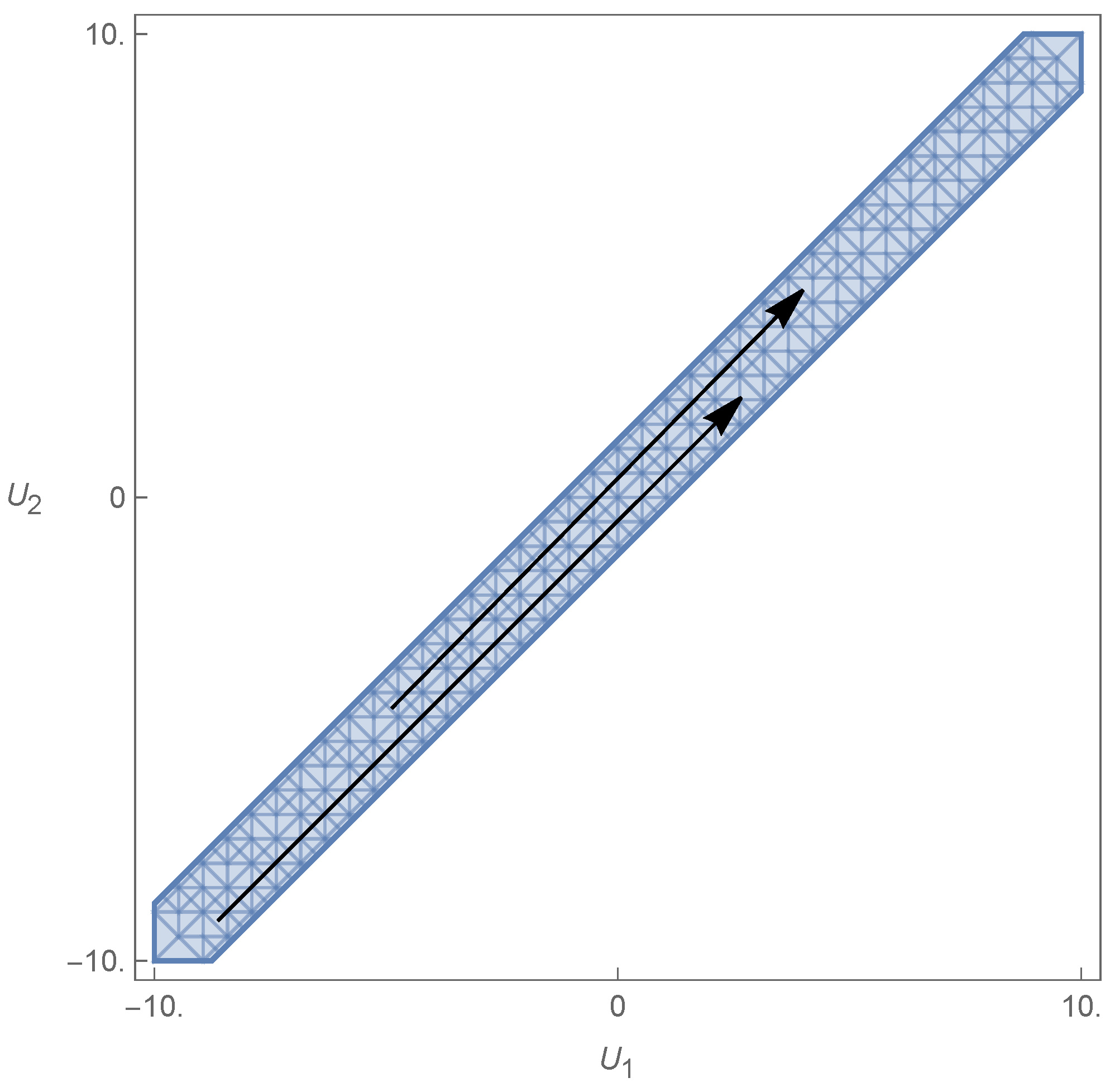
Any pair of velocities U 1 and U 2 can be taken into the first quadrant in the velocity space (cf. Figure 7) by a general translation by the same global added velocity U 0 . From Theorem 2, we can consider only the case of U 1 0 and U 2 0 without a loss of generality. The first quadrant is therefore all that it takes to determine the full results for the entire velocity space.

7. Symmetries

It is now necessary to address some properties of the problem under consideration, before the examples.

7.1. Problem Without Obstacles

The general problem without obstacles has two properties which come up as symmetries in the velocity space. These are as follows:
  • Under the general transformation U j U j + U 0 , j = 1 , 2 , the solutions of the dispersion relation change as ω i / k ω i / k + U 0 , i = 1 , , 4 , where ω / β ω / β + U 0 ;
  • Under a general inversion of the layer velocities ( U 1 , U 2 ) ( U 1 , U 2 ) , we find that the solutions of the dispersion relation become the symmetric of the ones before the inversion, although not necessarily because a solution has a functional dependence on U j , such that ω i ( U 1 , U 2 ) = ω i ( U 1 , U 2 ) , for the same i. The parameter Λ = ω 2 / g (therefore Λ ) is obviously invariant under this inversion. This means that the velocity space can be divided into two, since if one solves the problem for a pair ( U 1 , U 2 ) , one also solves for ( U 1 , U 2 ) . This is simply a left–right invariance in the general direction of the flows.

7.2. Problem with Obstacles

The problem with obstacles inherits properties from the free problem. These influence the sufficient condition, which is invariant under
  • U j U j + U 0 , j = 1 , 2 ;
  • ( U 1 , U 2 ) ( U 1 , U 2 ) .
The sufficient condition is an energy condition, dependent on the square of the speeds, which means that the problem is left–right symmetric.

7.3. Distinctions

In the first instance above, when there are no obstacles, adding U 0 means two different things that result in the same change: (a) adding a common speed to the fluid with respect to the observer or (b) the motion of the observer is such that in his reference frame, the fluid layers have an increase in their speeds of U 0 . One way or the other, the solutions of the dispersion relation are changed by the same amount, such that ω i / k ω i / k + U 0 . This, however, means that the lowest | ω i | may change with U 0 , implying that to obtain Λ , one must not simply add U 0 to ω / β but ascertain which one of the new solutions, after U 0 has been added, is now the smallest in absolute value. For example, if before | ω 1 | < | ω 2 | , now it may happen that | ω 1 + U 0 | > | ω 2 + U 0 | .
If we add obstacles to the problem, in order to obtain a sufficient condition for the existence of trapped modes, (a) and (b) above are no longer the same. Case (b) does not change the problem, just adds U 0 to the relevant quantities and, more importantly, does not change Λ , except through ω / β ω / β + U 0 for the observer. This is because of the change in the speed of the obstacles, which now move with respect to the observer. The relative motion of the layers with respect to the obstacles is the same, and the smallest | ω i | with respect to the obstacles remains the same, which means that Λ is the same. This is reflected in the invariance of the sufficient condition. On the other hand, case (a) changes the sufficient condition. If a common speed is added to the layers with respect to the obstacles, then the smallest | ω i | may change because the mode speeds have changed with respect to the obstacles (as noted above). Although the sufficient condition seems to be invariant under the addition of U 0 , one must now make sure that the correct Λ (or ω ) is used in the sufficient condition expression.
It becomes evident that in each domain of the velocity space where ω does not change (except through ω / β ω / β + U 0 ), the properties in Section 7.2 above are still valid. However, if a speed addition U 0 changes the solution of the smallest absolute value, then the sufficient condition is no longer invariant under global speed changes.
In the examples below, the allowed domain (velocity space) will be the intersection of the domain defined by the stability condition and the domain defined by the sufficient condition, with different pockets for different ω , determined by the smallest of the | ω i | , i = 1 , , 4 .

8. Examples

8.1. Column of Uniform Cross-Section

In this example (see Figure 8), we apply the sufficient condition to the paradigmatic setting of a vertical column that crosses both domains and all boundary surfaces between layers—in this case, a vertical column that stretches from z = to z > 0 and crosses both Γ 1 and Γ 0 . This is an approximation to a vertical object that stands in two layers deep enough to be much larger than the order of magnitude of the mode’s wavelength.
Directly applying the Formula (87), we find that
V Λ P = ρ 1 Θ 1 | Φ z ( 1 ) ( z ) | 2 + β 2 | Φ ( 1 ) ( z ) | 2 d x d y d z + ρ 2 Θ 2 | Φ z ( 2 ) ( z ) | 2 + β 2 | Φ ( 2 ) ( z ) | 2 d x d y d z ρ 1 Λ δ 1 Φ ( 1 ) ( 0 ) 2 meas ( θ 0 ) Λ ρ 2 ρ 1 ρ 2 δ 2 Φ ( 2 ) ( h 1 ) ρ 1 δ 1 Φ ( 1 ) ( h 1 ) 2 meas ( θ 1 ) .
The integrand functions do not depend on x or y, so the term meas ( θ 0 ) = meas ( θ 1 ) = S is common to all. It can be discarded from (89), and the latter becomes
ρ 1 | Φ z ( 1 ) ( z ) | 2 + β 2 | Φ ( 1 ) ( z ) | 2 d z + ρ 2 | Φ z ( 2 ) ( z ) | 2 + β 2 | Φ ( 2 ) ( z ) | 2 d z ρ 1 Λ δ 1 Φ ( 1 ) ( 0 ) 2 Λ ρ 2 ρ 1 ρ 2 δ 2 Φ ( 2 ) ( h 1 ) ρ 1 δ 1 Φ ( 1 ) ( h 1 ) 2 .
Integrating by parts in z and rearranging terms, such that the boundary conditions (76)–(80) can be directly applied, we find that the previous expression can be rendered as
Φ ( 1 ) ( 0 ) ρ 1 Φ ( 1 ) ( 0 ) z Φ ( 1 ) ( h 1 ) ρ 1 Φ ( 1 ) ( h 1 ) z + Φ ( 2 ) ( h 1 ) ρ 2 Φ ( 2 ) ( h 1 ) z ρ 1 Λ δ 1 Φ ( 1 ) ( 0 ) 2 Λ ρ 2 ρ 1 ρ 2 δ 2 Φ ( 2 ) ( h 1 ) ρ 1 δ 1 Φ ( 1 ) ( h 1 ) 2 = Φ ( 1 ) ( 0 ) ρ 1 Λ δ 1 2 Φ ( 1 ) ( 0 ) + ρ 2 Φ ( 2 ) ( h 1 ) δ 2 δ 1 ρ 1 Φ ( 1 ) ( h 1 ) Φ ( 1 ) ( h 1 ) z ρ 1 Λ δ 1 Φ ( 1 ) ( 0 ) 2 Λ ρ 2 ρ 1 ρ 2 δ 2 Φ ( 2 ) ( h 1 ) ρ 1 δ 1 Φ ( 1 ) ( h 1 ) 2 = 0
It is thus proven that V Λ P = 0 for a vertical column. We will from now on designate the terms related to the vertical column as V j * and P * ; thus, V * Λ P * = 0 . By a straightforward generalization of the proof found in [14,15,35] (see also in [19]), we can show that the vertical column generates trapped modes.

8.2. Obstacles That Always Satisfy the Sufficient Condition

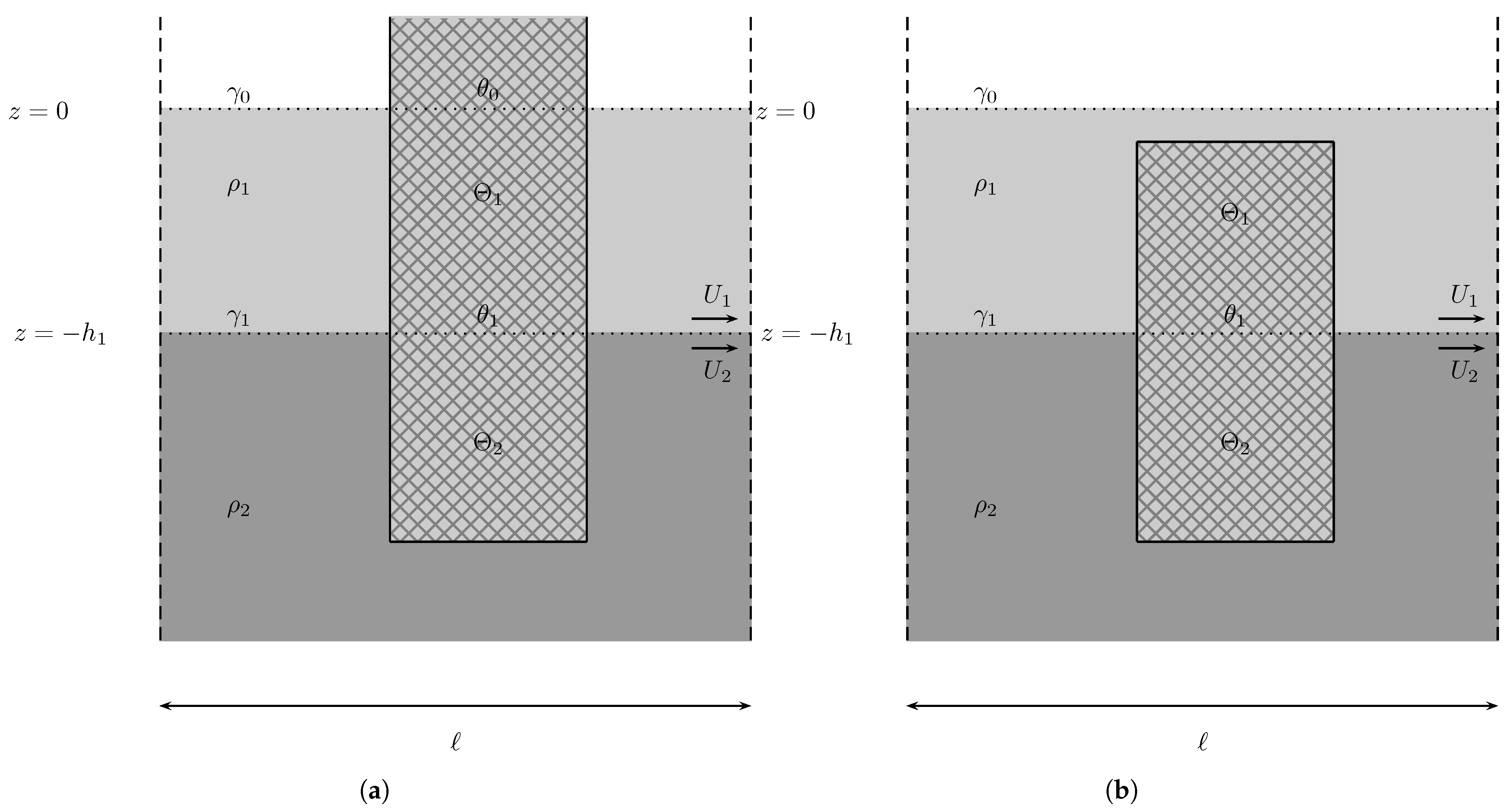
In Figure 9, the configuration on the left results in
V Λ P * > 0 ,
because V > V * . For the one on the right, we have a simple application of Corollary 1. Both results are immediate.

8.3. Obstacles That Partially Satisfy the Sufficient Condition

In both instances of Figure 10, we have V < V * , with P 0 = 0 and P 1 = P 1 * on the left and P 0 = P 0 * and P 1 = 0 on the right. On the left, there is a threshold distance from the free surface to the obstacle, ϵ ˜ > 0 , which results from demanding that
V Λ P 1 * = 0 .
If the distance ϵ between the top of the obstacle and the free surface is such that 0 < ϵ < ϵ ˜ , then the sufficient condition is met. If, on the other hand, ϵ ϵ ˜ , then the sufficient condition is not met. A similar situation happens with the obstacle on the right, where an interplay between ϵ 1 and ϵ 2 must now exist. Thus, for every small enough ϵ 1 > 0 , fixed, there is a threshold ϵ 2 ˜ , such that
V Λ P 0 * = 0 ,
where if 0 < ϵ 2 < ϵ 2 ˜ , the sufficient condition is met, and if ϵ 2 ϵ 2 ˜ , the sufficient condition is not met. However, if V 1 ( ϵ 1 ) is such that even in the limit V 2 V 2 * , still excluding P 1 * , we find V 1 ( ϵ 1 ) + V 2 * Λ P 0 * < 0 , then in that case, ϵ 2 ˜ 0 , and so the sufficient condition can never be met. The same applies with the roles of ϵ 1 and ϵ 2 reversed. In both examples, there is a finite non-null distance between the obstacle and the free surface (or the interface), such that in that interval, the sufficient condition is met. This means that these configurations always allow always given an appropriate distance from the free surface or interface, the meeting of the sufficient condition.

8.4. Obstacles That (Almost) Never Satisfy the Sufficient Condition

In Figure 11, all instances have V < V * . The example on the left has P = P * , whereas the example on the right has P 0 = 0 and P 1 = P 1 * . This implies that
V Λ P * < 0 ,
which means that the obstacle in Figure 11a never satisfies the sufficient condition.
Now, for the obstacle in Figure 11b, we have
V Λ P 1 * > 0 ,
if the distance from the top reduces to a value that it compensates for V 2 < V 2 * . Note, however, that Figure 11b is more difficult to satisfy than Figure 10a, since the former is the latter minus a portion of the volume of the obstacle in the second layer. The former has a threshold value for the maximal distance from the free surface necessarily smaller than the latter’s. It is thus a configuration where the sufficient condition is more difficult to meet. Even if we make V 2 V 2 * in Figure 11b, we still do not satisfy the sufficient condition, unless the top distance satisfies ϵ < ϵ ˜ (see the previous example).

8.5. Cavalieri’s Principle

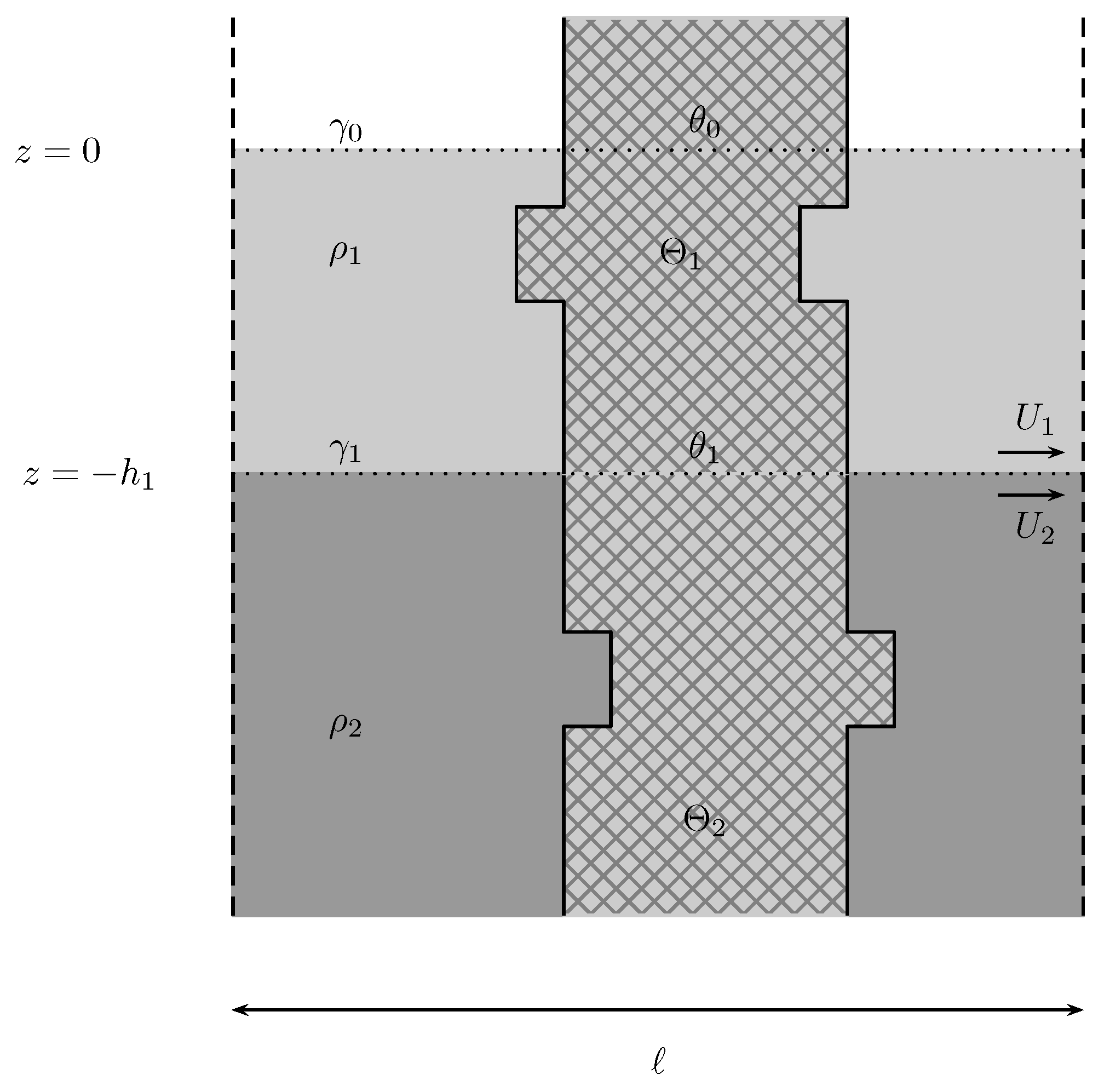
In Figure 12, we find that the integration of (90) is the same, despite the change in domain Θ j , j = 1 , 2 . This follows Cavalieri’s principle, which states that two objects situated between two parallel planes have equal volumes if, for every respective cross-section situated between these two given planes, the areas of the former are equal. Simply stated, any horizontal translation of sections of the obstacle that keep the cross-sectional areas changes nothing. This result is the same as the vertical column’s.
However, for the configurations in Figure 13, the expression in (89) does not reduce to (90). Cavalieri’s principle is no longer valid. For the general case, a conclusion is not possible. However, in the two instances of Figure 13, we can obtain a result due to the monoticity of the respective functions Φ ( z ) , if we assume V 1 = V 1 * in both cases. The volume of the depicted obstacles is the same as that of the vertical column. On the left of Figure 13, the example is that of a volume submerged in the second layer that is moved closer to the interface; on the right, the volume of the column has been translated a little further away instead Both cases stand outside the scope of Cavalieri’s principle. In the bottom layer, Φ ( z ) e z , such that the integrand of (89) is monotonically decreasing away from the interface. The integration of (89) on the left is, therefore, larger than V * , and the one on the right is smaller than V * . Since P = P * , we have V Λ P * > 0 on the left and V Λ P * < 0 on the right. We can infer that the left configuration in Figure 13 produces trapped modes; we cannot, however, conclude anything about the right configuration.
Let us now assume that V 1 V 1 * . If V 1 < V 1 * ; then, we have to verify case by case whether the change on the left satisfies the sufficient condition, since V 2 is larger than its starred counterpart. The configuration on the right, which already did not satisfy the sufficient condition when V 1 = V 1 * , is now further from satisfying the condition. If, on the other hand, V 1 > V 1 * , then the configuration on the left, which already did satisfy the condition when V 1 = V 1 * , satisfies it more robustly now. Whether the configuration on the right satisfies the sufficient condition has to be determined case by case, since V 2 < V 2 * .

8.6. Numerical Examples

As above, the examples below are meant to find the sufficient condition intersected by the stability region. All the regions depicted below are therefore the intersection of (87) with the stability condition Δ > 0 . One of the main purposes is to see the influence of the layer speeds on the sufficient condition, provided that there is a stable configuration. There are also depictions of the relation between some reference speed and another parameter or relation between parameters, such as the ratio of the layer densities ( ρ = ρ 1 / ρ 2 ) of the ratio between the layer depths ( h = h 1 / h 2 ).

8.6.1. Infinite Flute-like Column

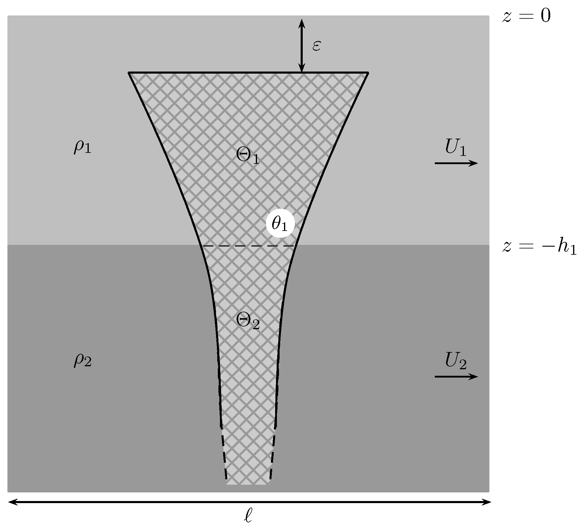
We consider now the case of a flute-like column obstacle (a solid of revolution) defined by its cut at x = 0 (see Figure 14),
{ ( y , z ) R 2 : z 0 1 2 z y 1 2 z } .
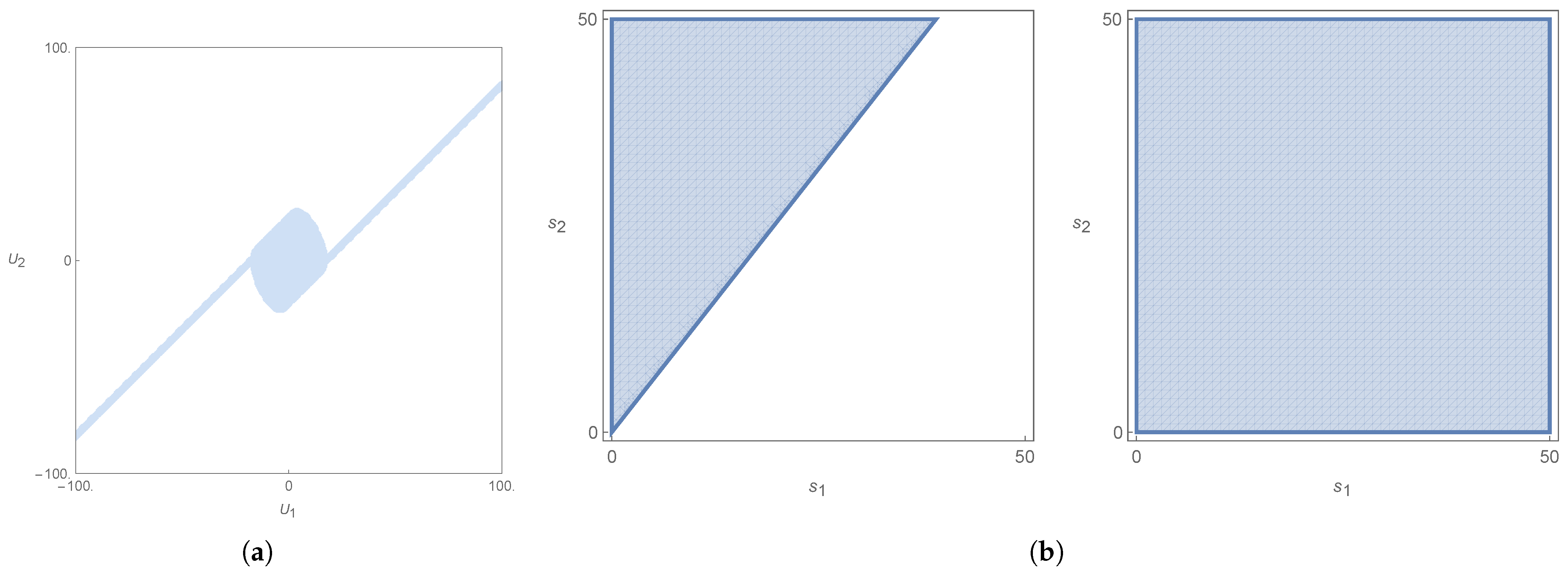
The region of stability and of where the sufficient condition is satisfied is given in the velocity space by Figure 15.
Only a partial region in the domain where ω 2 and ω 3 are the ω satisfies the sufficient condition. For the chosen parameters, the region where ω 1 / ω 4 are ω does not satisfy the condition. Given the fundamental right–left symmetry, when some region in the domain where ω 1 is ω satisfies the sufficient condition, then the region in the domain where ω 4 is ω which is linked to the former through a straight line passing through the origin also satisfies the sufficient condition. The same applies to the pair ω 2 and ω 3 .
We now add some changes in order to check the effects of the velocities on the different configurations given by an increasing distance from the free surface. Thus, the flute is now given by a variable distance from the free surface ( ε = α h 1 ), with 0 < α < 1 (see Figure 16)
{ ( y , z ) R 2 : z + ε 0 1 2 z y 1 2 z } .
Note that the flute does not descend. It is rather cut, increasing the distance from the newly cut base from the free surface. The region of stability and of the sufficient condition for the incomplete flute is shown in Figure 17.
It is visible now that, with P 0 = 0 , the sufficient condition is satisfied in the region where ω is given by ω 1 (or ω 4 ). The inner region progressively loses relevance, leaving only the outer region satisfying the sufficient condition. Ultimately, the sufficient condition is satisfied away from the origin of the velocity space when the flute’s base approaches the interface, whereas it was only satisfied near the origin when the base coincided with the free surface.
If we choose to compare to an incomplete column of uniform cross-section,
{ ( x , y , z ) R 3 : z + ε 0 x 2 + y 2 1 4 } ,
we find out that the regions are the same, regardless of the size of the gap between the top of the column and the free surface (see Figure 10),
Obviously, if the column is complete (Figure 8), the region is empty. However, below the free surface, the column always satisfies the sufficient condition in the realm where ω 1 (or ω 4 ) are ω and never inside, nearer the origin. Moreover, there is an indifference towards the distance ϵ from the top (Figure 18). This is different than the behavior of the flute.

8.6.2. Dumbbell-like Object

In this example, we have an object with a dumbbell-like shape. It is part of an incomplete column with an additional volume on the sides, keeping the original intersection with the interface. This is depicted in Figure 19.
The region where the sufficient condition is met must be part of the region of stability, as depicted for a set of parameters in Figure 2. Each set of parameters of the free problem will engender its own stability region. The region where the sufficient condition (87) is met must be part of this stability region. In this case, only the speed differences between layers matter, as seen above. This repeats what is seen in [25].
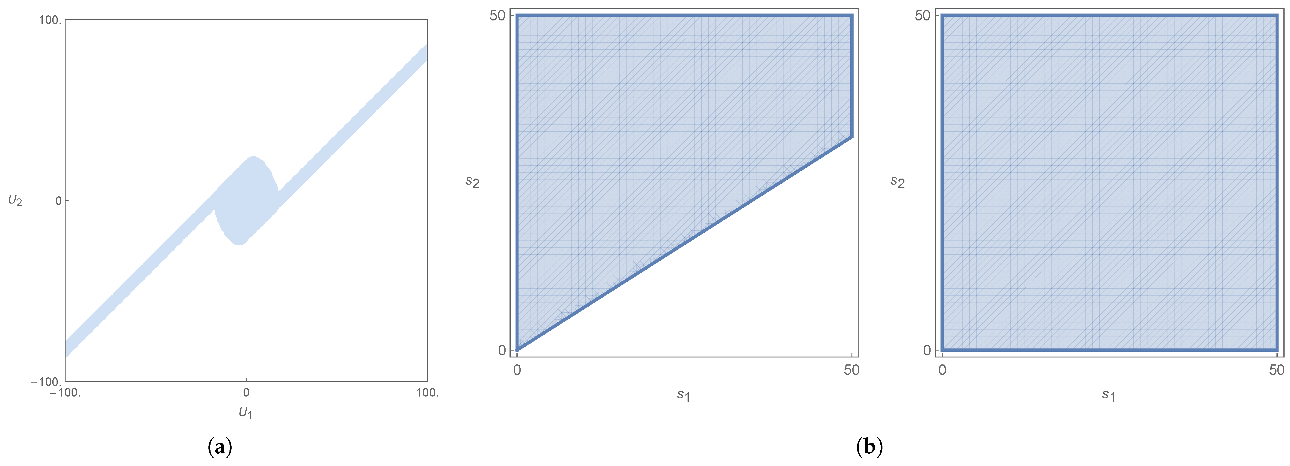
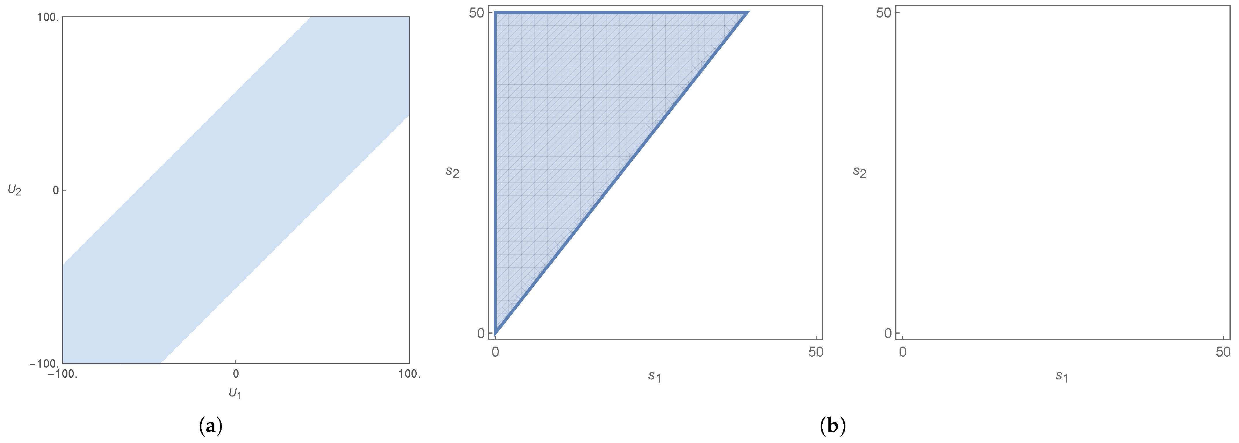
It is no longer true (in comparison to [25]) (see Figure 19), that if s 2 < s 1 , no sufficient condition is met (see Figure 20 and Figure 21). This stems from the fact that with s 2 < s 1 , we have an object that is less than a truncated column of the same height, with the truncated column being the case s 2 = s 1 . However, if there is a free surface (see [25] for the case without a free surface), it means that even a truncated column can satisfy the sufficient condition if it is close enough to the free surface (where P 0 subtracts from the sum) in such a way that V 1 + V 2 > Λ P 1 . It also matters whether the depth of the base of the column is deep enough, but in general, the bottom contribution to V 2 goes with e z . The case s 2 < s 1 may then still meet the sufficient condition, depending on the amount of V that is lost with regard to P 0 , when s 2 < s 1 . If s 2 > s 1 (see Figure 22 and Figure 23), it all depends on the balance of terms, but there is no barrier of principles preventing the object from satisfying the sufficient condition. All this discussion applies equally to all values of the velocities U j and j = 1 , 2 within the stability domain.
Another aspect to consider is the loss of symmetry with respect to the interface. In [25] there were two semi-infinite layers divided by an interface. Now, however, there is a free surface. The independence of the sufficient condition (Equation (87)) with regard to the values of U j , j = 1 , 2 , when the object was symmetrically disposed with respect to the interface, no longer applies. This is visible below in Figure 21 and Figure 22, when on the left, the ( s 1 , s 2 ) region plots are different than those on the right, and for some change in one of the velocities U j , j = 1 , 2 .
We saw earlier that ρ is not beneficial to stability, whereas h 1 is (Section 4). The increase from h 1 = 100 and ρ = 0.1 to h 1 = 250 and ρ = 0.5 should in principle be worse off, given the greater influence of ρ against stability. Here, globally, we see that this increase reduces the region where the stability/sufficient condition is met ( ( U 1 , U 2 ) plots). However, the ( s 1 , s 2 ) region plots increase in area with the same change. There are generally too many parameters that can be changed in order to establish a coherent picture; however, what we have shown allows for a sufficiently clear picture of the influences of those parameters on the results.

9. Conclusions

In this paper, it was possible to examine the existence of trapped modes along periodic arrays of obstacles submerged in a two-layer fluid topped by a free surface. The chosen framework was that of the linear water wave theory of irrotational, inviscid fluids. The setup consisted of two horizontally infinite, immiscible layers of different constant densities, gravitationally and dynamically stable, with a respective and independent uniform velocity background in the same direction as the wave-mode propagation. The purpose of our work was to investigate the influence of this uniform motion in the sufficient condition for the existence of trapped modes (already derived for static layers in [15,16,17,18,19,20,21]) and for semi-infinite moving layers in the vertical direction [25]. We considered exclusively progressive waves ( β > 0 ).
A linear spectral problem with the parameter Λ = ω 2 / g is not allowed by the horizontal velocities of the layers. However, using the velocity scale provided by the mode velocity c = ω / β , the original problem (with a linearized spectral problem) can be generalized to uniformly moving layers. The sufficient condition is obtained from the norm of the operator T, evaluated by use of a perturbation around the solution ϕ . The velocity scale is therefore already present in the sufficient condition. It becomes reasonable to set this scale to linearize the original problem.
The main results on static configurations with free surface and the previous paper’s semi-infinite configuration [25] in terms of the velocity component are recovered. In addition to the necessary gravitational stability condition ρ 2 > ρ 1 , the stability condition in Figure 2 must be met as well. The dependence on the velocities by the stability condition is as | U 1 U 2 | , just as it was in [25]. The sufficient condition is invariant under U j U j + U 0 formally. However, unlike in [25], the possible change in ω between the solutions ω j when U j U j + U 0 makes this sufficient condition only partially invariant under global additions of velocity.
In both cases, there is an invariance under global velocity additions (contingent on changes in ω ). All the results can be obtained for the I quadrant of the velocity space, shown in Figure 2a–c, and from there, they can be extended to the entire velocity domain. Despite there being four ω j , the ( U 1 , U 2 ) -plane can still be divided between the sets of ω solutions. Given the global invariance of the stability and sufficient conditions under U j U j + U 0 , the system can be studied entirely inside the first quadrant in ( U 1 , U 2 ) . In this configuration of two layers with a free surface, symmetry no longer plays a role regarding the influence of U 1 and U 2 . The final example (Section 8.6.2) shows that what in [25] did not depend on the values of U 1 and U 2 now does (see Figure 21 and Figure 22).
The domain of velocities for the sufficient condition is now a region inside the band of slope one granted by the stability condition (see, e.g., Figure 2). The sufficient condition is constant along a given line of slope one, depending now also on the value of ω , but may change from line to line (modulo the change in ω ). There is no symmetry with respect to the line U 2 = U 1 (such as there is in the case of the stability condition) because the sufficient condition is sensitive to the sign of U 1 U 2 . In the case of cross-section plots ( s 1 , s 2 ) , we could observe the influence of the change in layer velocity, such as what did not happen in [25].
It was possible to confirm that results, such as the vertical column and the comparisons with it, and the comparisons within the purview of Cavalieri’s principle (Section 8.1, Section 8.2, Section 8.3, Section 8.4 and Section 8.5), apply in the two-layer-with-free-surface case as well. The symmetry results, however, no longer apply, since the introduction of the free surface undoes the symmetry existing in [25]. Further developments in a multi-layer configuration are now warranted, especially in the three-layer case, which is relevant in many applications. It remains to be seen how far this formalism can be taken, before technical barriers show.

Author Contributions

The two authors contributed equally to this work: Conceptualization, G.D.; methodology, G.D.; software, B.P.; validation, G.D. and B.P.; formal analysis, G.D. and B.P.; investigation, G.D. and B.P.; resources, G.D. and B.P.; writing—original draft preparation, G.D. and B.P.; writing-review and editing, G.D. and B.P. All authors have read and agreed to the published version of the manuscript.

Funding

This research received no external funding.

Data Availability Statement

Data is contained within the article.

Conflicts of Interest

The authors confirm their independence and that they have no conflicts of interest regarding this publication.

Abbreviations/Nomenclature

β                                    Wavenumber in the y-direction, β ( 0 , π l ] , for wave periodicity.
Δ Discriminant of the dispersion relation for dynamical stability.
δ j Doppler factor, δ j = 1 U j c , c = ω β , j = 1 , 2 .
η ( x , y , t ) Top interface elevation (layers 1 and 2), at z = 0 .
ζ ( x , y , t ) Bottom interface elevation (layers 2 and 3), at z = h 1 .
γ 0 Unpierced free surface, γ 0 = { ( x , y , z ) ϖ 1 ϖ 2 : z = η ( x , y , t ) } .
γ 1 Unpierced interface, γ 1 = { ( x , y , z ) ϖ 2 ϖ 3 : z = ζ ( x , y , t ) } .
Γ 0 Top interface surface, Γ 1 = { ( x , y , z ) : y ( 0 , l ) , z = η ( x , y , t ) } .
Γ 1 Bottom interface surface, Γ 2 = { ( x , y , z ) : y ( 0 , l ) , z = ζ ( x , y , t ) } .
θ 0 Pierced free interface, θ 1 = { ( x , y , z ) Θ 1 ¯ Θ 2 ¯ : z = 0 } .
θ 1 Pierced interface, θ 2 = { ( x , y , z ) Θ 2 ¯ Θ 3 ¯ : z = h 1 } .
Λ Spectral parameter, Λ = ω 2 g , g is gravity.
Λ Threshold spectral parameter, Λ = ω 2 g .
μ Inverse spectral parameter, μ = Λ 1 .
μ Threshold inverse spectral parameter, μ = Λ 1 .
ρ j Fluid density in layer j, ρ 3 > ρ 2 > ρ 1 > 0 , j = 1 , 2 .
σ j Obstacle surface in layer j, σ j = { ( x , y , z ) ϖ j : y ( 0 , l ) , z Ξ j } , j = 1 , 2 .
σ c ( T ) Continuous spectrum of operator T, σ c ( T ) = ( 0 , μ ] .
σ d ( T ) Discrete spectrum of operator T, for trapped modes.
σ e ( T ) Essential spectrum of operator T, σ e ( T ) = [ 0 , μ ] .
τ Operator norm of T, τ = sup φ H β { 0 } T φ , φ φ , φ .
ϕ ( j ) Velocity potential in layer j, ϕ ( j ) = Re e i ω t φ ( j ) + φ B ( j ) , j = 1 , 2 .
ϕ ( j ) Threshold potential, ϕ ( j ) ( y , z ) = e i β y Φ ( j ) ( z ) , j = 1 , 2 .
φ ( j ) Time-harmonic potential in layer j, j = 1 , 2 .
φ B ( j ) Background flow potential, U j y for r > r 0 , j = 1 , 2 .
φ ϵ ( j ) Trial function, φ ϵ ( j ) = e ϵ | x | ϕ ( j ) ( y , z ) , j = 1 , 2 .
φ j Primed potential, φ j = φ ( j ) δ j , j = 1 , 2 .
Φ ( j ) ( z ) z-dependent threshold potential component, j = 1 , 2 .
ψ ( j ) Test function in layer j, in C c ( ϖ j ¯ ) or H β ( ϖ j ) , j = 1 , 2 .
ψ j Primed test function, ψ j = ψ ( j ) δ j , j = 1 , 2 .
ϖ j Fluid region, ϖ j = Π j Θ j ¯ , j = 1 , 2 .
ϖ r 0 , j Subregion of ϖ j within distance r 0 from obstacle.
ω Radian frequency, ω > 0 .
ω Smallest non-trivial dispersion relation frequency.
ω i Dispersion relation roots, i = 1 , 2 , 3 , 4 , ordered ω 1 < ω 2 < ω 3 < ω 4 .
AInterface term in variational formulation.
B , C , D , E , G , H Threshold solution coefficients.
cMode speed, c = ω β .
c Threshold mode speed, c = ω β .
f B ( j ) Background flow function, ≈ U j y at r = r 0 , j = 1 , 2 .
gGravitational acceleration, g > 0 .
h 1 Top layer thickness.
kTotal wavenumber in x- and y-directions.
lObstacle array periodicity in y-direction.
nOutward normal vector into obstacles.
PInterface terms, P = P 1 + P 2 , for pierced interfaces.
P Δ , D Δ Stability functions for real solutions.
rDistance to nearest obstacle, r = | x | .
r 0 Distance from obstacle boundaries.
TTrace-interface operator, T φ = μ φ .
U j y-direction velocity in layer j, j = 1 , 2 .
U 0 Uniform velocity shift for all layers.
VVolume terms, V = V 1 + V 2 , for obstacle energy.
H β Function space for quasi-periodic potentials.
H β ( ϖ j ) Subspace of H 1 ( ϖ j ) with quasi-periodicity, j = 1 , 2 .
Ξ j Fluid domains: Ξ 1 = R 2 × ( η , + ) , Ξ 2 = R 2 × ( ζ , η ) , Ξ 3 = R 2 × ( , ζ ) .
Π j Periodicity cell, Π j = { ( x , y , z ) Ξ j : y ( 0 , l ) } , j = 1 , 2 .
Θ j Obstacle in layer j, in Π j , j = 1 , 2 .

Appendix A. Finite Lower Layer on a Flat Bottom
The analysis in Section 3 can be easily reworked for the case of a finite bottom layer on a flat bottom situated at z = h 2 . In (12) we now include the bottom frontier as part of σ 2 . This implies that in the linear equations we add
φ ( 2 ) z = 0 at z = h 2 .
The new ansatz for the potential of the lower layer is
φ ( 2 ) ( x , y , z ) = C ̲ e i β y e ± i k 2 β 2 x cosh k ( z + h 2 ) .
The new dispersion relation is then given by
e k h 1 1 e 2 h 1 k g 2 k 2 ( ρ 2 ρ 1 ) + 1 + e 2 h 1 k g k ρ 2 ω U 1 β 2 e 2 h 1 k 1 ρ 1 ω U 1 β 4 sinh k ( h 2 h 1 ) 2 ρ 2 ω U 2 β 2 cosh k ( h 2 h 1 ) ω U 1 β 2 cosh ( k h 1 ) g k sinh ( k h 1 ) = 0 .
We obtain as well three different functions Δ , P Δ and D Δ as functions of ( U 2 U 1 ) 2 . The stability region obtained from the intersection of Δ > 0 , P Δ < 0 and D Δ < 0 is depicted in Figure A1.
Figure A1. Stability region plot for h 1 = 3.5 , h 2 = 10.5 , ρ 1 = 0.925 , ρ 2 = 1 and β = k = 1 .
Axioms 14 00846 g0a1
In terms of stability the addition of a flat bottom appears to bring no changes for the used parameter values in this example (compare Figure A1 with Figure 2a).
The stability condition depends now on the depth of the lower layer at z = h 2 . From Figure A2 one sees that with a small density ratio ρ = ρ 1 / ρ 2 = 0.1 the increase in h 2 from one tenth to two and a half times the depth of the top layer h 1 has the effect of closing the gaps in the stability region (notice the lines in Figure A2a,d) as well as causing some smoothing and change in the regions where ω 2 and ω 3 are the ω . In addition, an implicit elliptic figure in the root signal plots is enlarged with the increase in h 2 (Figure A2c,f,i). Still, the effect is small.
Figure A2. Stability region plot with parameters ( a c ) h 2 = 10.5 , ( d f ) h 2 = 50 , ( g i ) h 2 = 250 , with h 1 = 100 , ρ 1 = 0.1 and ρ 2 = 1 , plus β = k = π / 100 .
Axioms 14 00846 g0a2
Next, doing the same kind of change to the lower layer depth with respect to the top layer (see Figure A3), but with ρ = ρ 1 / ρ 2 = 0.5 , the changes to the different plots are not easily detectable. The conclusion to draw is that with a larger ρ the influence of the lower layer is barely discernable. However, in comparison with Figure A2, the regions are narrower, as was already seen in the infinitely deep lower layer case (Figure 5). A larger ρ leads to a narrower stability region in the U j , j = 1 , 2 . For ρ = 0.5 , even h 2 = 50 = h 1 / 2 is already identical to the infinite case in Figure 5c,d.
Figure A3. Stability region plot with parameters ( a c ) h 2 = 50 , ( d f ) h 2 = 100 , , with h 1 = 100 , ρ 1 = 0.5 and ρ 2 = 1 , plus β = k = π / 100 . Making h 2 = 1000 would make no discernable difference.
Axioms 14 00846 g0a3
Figure A4 shows the same as in Figure A3a–c, this time for a much larger density ratio, ρ = 0.925 . With the exception of the width, the graphs are virtually equal. Also, and more striking, Figure A4 is equal to Figure 4e,f. So, in this situation, h 2 = h 1 / 2 = 50 means that the lower layer is as good as infinite.
Figure A4. Stability region plot with velocity region in (a), root type in (b) and root signal in (c). Parameters used were h 1 = 100 , h 2 = 50 , ρ 1 = 0.925 and ρ 2 = 1 , plus β = k = π / 100 .
Axioms 14 00846 g0a4
Finally, if we reduce h 1 to mere h 1 = 10 (see Figure A5), and keep the density ratio high enough, at ρ = 0.5 , we see a new dependance on h 2 . In fact, with h 2 = 1 10 100 and h 1 = 10 , the increase in the lower layer’s depth seems to work against stability. There is, moreover, a much more complicated pattern in the root-type and signal plots. In plot Figure A2, the increase in h 2 seemed to help stability. Here, on the other hand, it works against it.
Figure A5. Stability region plot with parameters ( a c ) h 2 = 1 , ( d f ) h 2 = 10 , ( g i ) h 2 = 100 , with h 1 = 10 , ρ 1 = 0.5 and ρ 2 = 1 , plus β = k = π / 100 .
Axioms 14 00846 g0a5
Finally, and without any discernable change from the infinite case, β also works against stability, by making the region narrower, much like the density ratio ρ . Additionally, small β generates a more complex pattern on stability when h 1 is small. If β = k = 1 , as in Figure 2a–c, no problem comes from having h 1 = 3.5 . However, in Figure A5, we find that a small β = k = π / 100 leads to more complex pattern for smaller h 1 , in this case h 1 = 10 . A higher value of β = k allows a lower value of h 1 , before reaching regions of a much more complicated stability pattern. All this can be gleaned from Figure A6. It is the same as Figure A5, but for a larger value of β and k.
Figure A6. Stability region plot with parameters ( a , b ) h 2 = 1 , ( c , d ) h 2 = 10 , with h 1 = 10 , ρ 1 = 0.5 and ρ 2 = 1 , plus β = k = π / 12 . Making h 2 = 100 would make no discernable difference from h 2 = 10 .
Axioms 14 00846 g0a6
All in all, if the first layer is large enough with respect to β and k, for a ratio such that ρ < 0.5 , h 2 is slightly helpful to stability. If ρ 1 , then h 2 is quite indifferent. Only for small h 1 is h 2 impeditive of stability. This smallness of h 1 is dependent on β and k. Smaller values of β and k result in a higher threshold for h 1 . For values of h 1 above this threshold, and almost any ρ , if h 2 h 1 / 2 , the stability is for all intents and purposes the same as for the case h 2 . For fixed values of the other parameters, β narrows the stability band width. The same goes for ρ .
The new Φ ( 2 ) ( z ) is given by the ansatz
Φ ( 2 ) ( z ) = C ̲ cosh k ( z + h 2 ) .
The new coefficients for the solutions corresponding to the parameter Λ are
A ̲ = ( ω β U 1 ) β g + ( ω β U 1 ) 2 ,
B ̲ = ( ω β U 1 ) β g ( ω β U 1 ) 2 ,
C ̲ = 2 csch β ( h 2 h 1 ) ( ω β U 2 ) cosh ( β h 1 ) ( ω β U 1 ) 2 β g sinh ( β h 1 ) ,
E ̲ = 2 i β ( ω U 1 β ) 2 ,
F ̲ = 2 i β cosh ( β h 1 ) ( ω β U 1 ) 2 β g sinh ( β h 1 ) .
Note that the only change that takes place is in C ̲ , the rest of the coefficients being the same. There is now a dependence on h 2 . The invariance under ( U 1 , U 2 ) ( U 1 + U 0 , U 2 + U 0 ) is obviously maintained. From the above, we decided to circumscribe our examples to the infinite case, since real world values and relations would make any of our finite-depth examples virtually indistinguishable from the infinite case.

References

  1. Kuznetsov, N.; Maz’ya, V.; Vainberg, B. Linear Water Waves: A Mathematical Approach; Cambridge University Press: Cambridge, UK, 2002. [Google Scholar]
  2. Stokes, G.G. Report on recent researches in hydrodynamics. Rep. Br. Assoc. Adv. Sci. 1846, 16, 1–20. [Google Scholar]
  3. Ursell, F. Trapping modes in the theory of surface waves. Math. Proc. Camb. Philos. Soc. 1951, 47, 347–358. [Google Scholar] [CrossRef]
  4. Ursell, F.; Taylor, G.I. Edge waves on a sloping beach. Proc. R. Soc. Lond. Ser. A Math. Phys. Sci. 1952, 214, 79–97. [Google Scholar] [CrossRef]
  5. John, F. On the motion of floating bodies II. Simple harmonic motions. Commun. Pure Appl. Math. 1950, 3, 45–101. [Google Scholar] [CrossRef]
  6. Simon, M.J.; Ursell, F. Uniqueness in linearized two-dimensional water-wave problems. J. Fluid Mech. 1984, 148, 137–154. [Google Scholar] [CrossRef]
  7. Evans, D.V.; Levitin, M.; Vassiliev, D. Existence theorems for trapped modes. J. Fluid Mech. 1994, 261, 21–31. [Google Scholar] [CrossRef]
  8. McIver, M. An example of non-uniqueness in the two-dimensional linear water wave problem. J. Fluid Mech. 1996, 315, 257–266. [Google Scholar] [CrossRef]
  9. Linton, C.M.; McIver, P. Embedded trapped modes in water waves and acoustics. Wave Motion 2007, 45, 16–29. [Google Scholar] [CrossRef]
  10. Kuznetsov, N. Trapped modes of internal waves in a channel spanned by a submerged cylinder. J. Fluid Mech. 1993, 254, 113–126. [Google Scholar] [CrossRef]
  11. Linton, C.M.; Cadby, J.R. Trapped modes in a two-layer fluid. J. Fluid Mech. 2003, 481, 215–234. [Google Scholar] [CrossRef]
  12. Kuznetsov, N.; McIver, M.; McIver, P. Wave interaction with two-dimensional bodies floating in a two-layer fluid: Uniqueness and trapped modes. J. Fluid Mech. 2003, 490, 321–331. [Google Scholar] [CrossRef]
  13. Cal, F.S.; Dias, G.A.S.; Nazarov, S.A.; Videman, J.H. Linearised theory for surface and interfacial waves interacting with freely floating bodies in a two-layer fluid. Z. Angew. Math. Phys. 2015, 66, 417–432. [Google Scholar] [CrossRef]
  14. Nazarov, S.A.; Videman, J.H. A sufficient condition for the existence of trapped modes for oblique waves in a two-layer fluid. Proc. R. Soc. A Math. Phys. Eng. Sci. 2009, 465, 3799–3816. [Google Scholar] [CrossRef]
  15. Kamotskii, I.; Nazarov, S. Exponentially decreasing solutions of the problem of diffraction by a rigid periodic boundary. Math. Notes 2003, 73, 129–131. [Google Scholar] [CrossRef]
  16. Nazarov, S.A. A simple method for finding trapped modes in problems of the linear theory of surface waves. Dokl. Math. 2009, 80, 914–917. [Google Scholar] [CrossRef]
  17. Nazarov, S.A. Sufficient conditions for the existence of trapped modes in problems of the linear theory of surface waves. J. Math. Sci. 2010, 167, 713–725. [Google Scholar] [CrossRef]
  18. Nazarov, S.A.; Videman, J.H. Existence of edge waves along three-dimensional periodic structures. J. Fluid Mech. 2010, 659, 225–246. [Google Scholar] [CrossRef]
  19. Cal, F.S.; Dias, G.S.A.; Videman, J.H. Existence of trapped modes along periodic structures in a two-layer fluid. Q. J. Mech. Appl. Math. 2012, 65, 273–292. [Google Scholar] [CrossRef]
  20. Cal, F.S.; Dias, G.A.S.; Pereira, B.M.M.; Videman, J.H. Edge waves propagating in a two-layer fluid along a periodic coastline. J. Eng. Math. 2014, 85, 1–17. [Google Scholar] [CrossRef]
  21. Cal, F.S.; Dias, G.A.S.; Pereira, B.M.M.; Videman, J.H. Trapped modes in a multi-layer fluid. Q. J. Mech. Appl. Math. 2021, 74, 34–54. [Google Scholar] [CrossRef]
  22. Wilcox, C.H. Scattering Theory for Diffraction Gratings; Springer: Berlin, Germany, 1984. [Google Scholar]
  23. Nazarov, S. Trapped surface waves in a periodic layer of a heavy liquid. J. Appl. Math. Mech. 2011, 75, 235–244. [Google Scholar] [CrossRef]
  24. Craig, W.; Guyenne, P.; Sulem, C. The surface signature of internal waves. J. Fluid Mech. 2012, 710, 277–303. [Google Scholar] [CrossRef]
  25. Dias, G.A.S. Trapped modes along periodic structures submerged in a two-layer fluid with background steady flow. Math. Methods Appl. Sci. 2023, 46, 18274–18299. [Google Scholar] [CrossRef]
  26. Lamb, H. Hydrodynamics, 6th ed.; Cambridge University Press: Cambridge, UK, 1932. [Google Scholar]
  27. Paterson, A.R. A First Course in Fluid Dynamics; Cambridge University Press: Cambridge, UK, 1983. [Google Scholar] [CrossRef]
  28. Kundu, P.; Cohen, I. Fluid Mechanics; Elsevier Science: Amsterdam, The Netherlands, 2010. [Google Scholar]
  29. Drazin, P. DYNAMICAL METEOROLOGY|Kelvin–Helmholtz Instability. In Encyclopedia of Atmospheric Sciences, 2nd ed.; North, G.R., Pyle, J., Zhang, F., Eds.; Academic Press: Oxford, UK, 2015; pp. 343–346. [Google Scholar] [CrossRef]
  30. Irving, R.S. Integers, Polynomials, and Rings: A Course in Algebra; Springer: New York, NY, USA, 2004. [Google Scholar] [CrossRef]
  31. Evans, L. Partial Differential Equations; Graduate studies in mathematics; American Mathematical Society: Providence, RI, USA, 2010. [Google Scholar]
  32. Evans, L.C.; Gariepy, R.F. Measure Theory and Fine Properties of Functions; CRC Press: New York, NY, USA; London, UK, 1992. [Google Scholar]
  33. Birman, M.S.; Solomjak, M.Z. Spectral Theory of Self-Adjoint Operators in Hilbert Space; D. Reidel Publishing Company: Boston, MA, USA, 1987. [Google Scholar]
  34. Dean, R.; Dalrymple, R. Water Wave Mechanics for Engineers and Scientists; World Scientific: Singapore, 1991. [Google Scholar]
  35. Linton, C.M.; Mciver, M. The existence of Rayleigh–Bloch surface waves. J. Fluid Mech. 2002, 470, 85–90. [Google Scholar] [CrossRef]
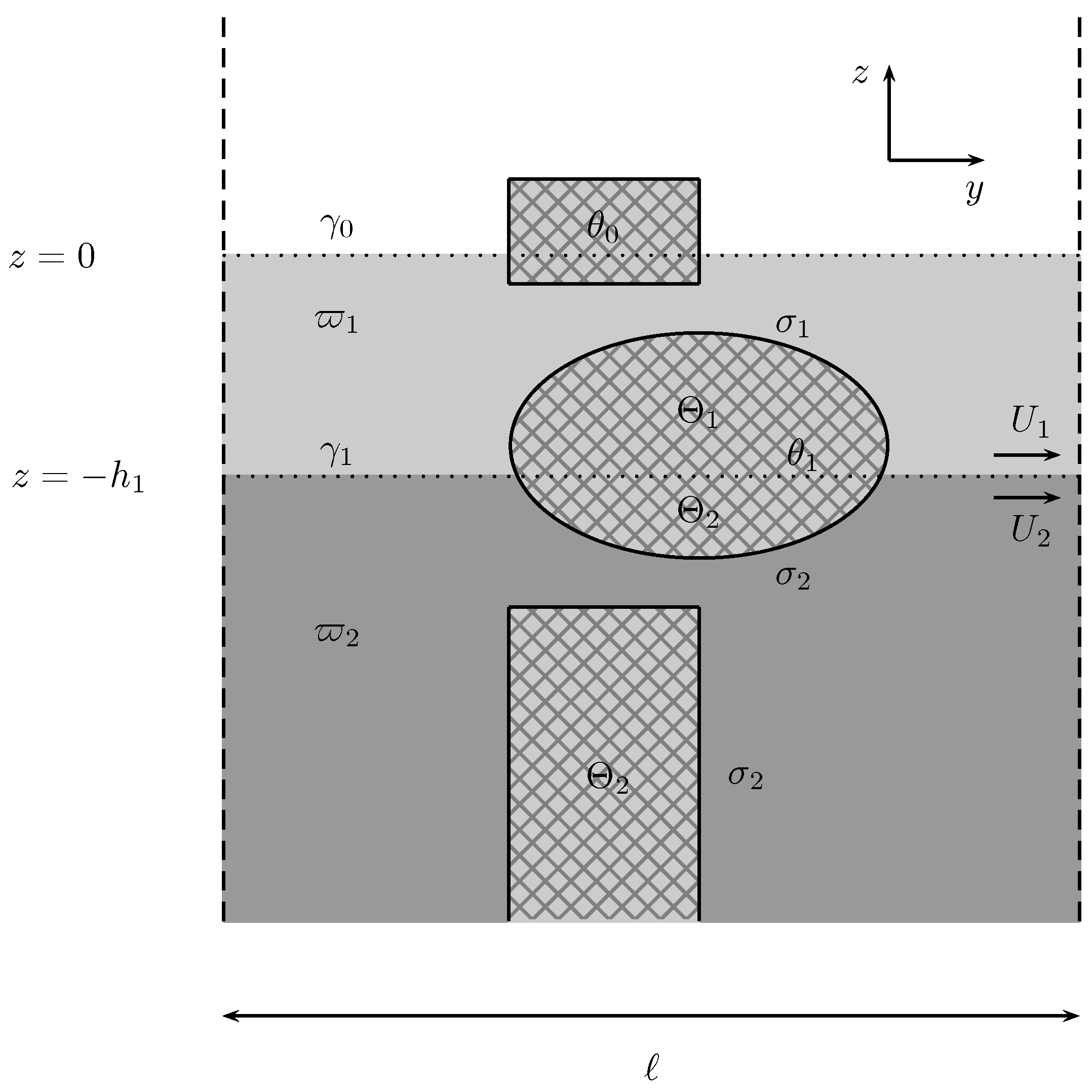
Figure 1. Model periodic cell with general fixed obstacles.
Axioms 14 00846 g001
Figure 2. Graphic depiction of the stability inequalities: in (a) we have the stability region for Δ , in (b) for P Δ and in (c) for D Δ . Parameters used were h 1 = 3.5 , ρ 1 = 0.925 , and ρ 2 = 1 , plus β = k = 1 .
Axioms 14 00846 g002
Figure 3. Stability region by smallest | ω i | | ω | : (a) regions according to which ω i is ω ; (b) signal of ω . This is superimposed on the Δ > 0 plot with parameters h 1 = 3.5 , ρ 1 = 0.925 , and ρ 2 = 1 , plus β = k = 1 .
Axioms 14 00846 g003
Figure 4. Stability region plot with parameters h 1 = 100 , ( a , b ) ρ 1 = 0.1 , ( c , d ) ρ 1 = 0.5 , ( e , f ) ρ 1 = 0.925 , and ρ 2 = 1 , plus β = k = π / 100 .
Axioms 14 00846 g004
Figure 5. Stability region plot with parameters ( a , b ) h 1 = 25 , ( c , d ) h 1 = 250 , with ρ 1 = 0.5 and ρ 2 = 1 , plus β = k = π / 100 .
Axioms 14 00846 g005
Figure 6. Stability region plot with parameters (a) by type and (b) by signal. Parameters used: h 1 = 100 , ρ 1 = 0.1 , ρ 2 = 1 , plus β = k = 1 .
Axioms 14 00846 g006
Figure 7. Invariance under global velocity additions in the stability region.
Axioms 14 00846 g007
Figure 8. Schematic of the column of uniform cross-section.
Axioms 14 00846 g008
Figure 9. Obstacles that satisfy the sufficient condition: in (a) the obstacle crosses both the interface and the free surface, whereas in (b) it does not cross either. The analysis is made by comparison with the vertical column of constant cross-section.
Axioms 14 00846 g009
Figure 10. Obstacles that conditionally satisfy the sufficient condition by comparison with the vertical column of constant cross-section: in (a) the obstacle does not cross the free-surface and in (b) it does not cross the interface.
Axioms 14 00846 g010
Figure 11. Obstacles that never satisfy the sufficient condition (a) or that can satisfy the sufficient condition (b) by comparison with the vertical column of constant cross-section.
Axioms 14 00846 g011
Figure 12. Obstacle that satisfies the sufficient condition by comparison with the vertical column of constant cross-section using Cavalieri’s principle.
Axioms 14 00846 g012
Figure 13. Obstacles that cannot be directly compared with the vertical column using Cavalieri’s principle. The object in (a) has material translated to closer to the interface, whereas in (b) the material has been moved farther from the interface.
Axioms 14 00846 g013
Figure 14. Flute-like column over an infinite bottom layer, crossing the interface and having its top surface coincident with the intersection with the free surface.
Axioms 14 00846 g014
Figure 15. Sufficient condition and stability region of the complete flute for h 1 = 3.5 ,   ρ 1 = 0.925 ,   ρ 2 = 1 ,   β = 1 ,   l = 2 .
Axioms 14 00846 g015
Figure 16. Flute-like column over an infinite bottom layer, crossing the interface, and having its top surface a distance ε below the free surface.
Axioms 14 00846 g016
Figure 17. Sufficient condition and stability region for the incomplete flute for h 1 = 3.5 ,   ρ 1 = 0.925 ,   ρ 2 = 1 ,   β = 1 ,   l = 2 and, respectively, (a) ε = 0.1 h 1 , (b) ε = 0.5 h 1 and (c) ε = 0.9 h 1 .
Axioms 14 00846 g017
Figure 18. Sufficient condition and stability region for an incomplete column with ρ 1 = 0.925 ,   ρ 2 = 1 ,   h 1 = 3.5 ,   β = 1 ,   l = 2 , with ε = 0.1 h 1 , 0.5 h 1 , and 0.9 h 1 .
Axioms 14 00846 g018
Figure 19. Dumbbell astride the interface.
Axioms 14 00846 g019
Figure 20. Stability and sufficientcondition for (a) ( U 1 , U 2 ) and (b) ( s 1 , s 2 ) regions, with ρ 1 = 0.5 ,   ρ 2 = 1 ,   h 1 = 250 ,   β = π / 100 ,   l = 100 , and dumbbell obstacle given by d 1 = d 3 = 10 and d 2 = d 4 = 5 . Left ( s 1 , s 2 ) plot has ( U 1 , U 2 ) = ( 20 , 50 ) , and right plot has ( U 1 , U 2 ) = ( 50 , 50 ) . Note that the difference between the left and right ( s 1 , s 2 ) region plot lies only in the values of U 1 .
Axioms 14 00846 g020
Figure 21. Stability and sufficient condition for (a) ( U 1 , U 2 ) and (b) ( s 1 , s 2 ) regions, with ρ 1 = 0.5 ,   ρ 2 = 1 ,   h 1 = 250 ,   β = π / 100 ,   l = 100 , and dumbbell obstacle given by d 1 = d 3 = 10 and d 2 = d 4 = 20 . Left ( s 1 , s 2 ) plot has ( U 1 , U 2 ) = ( 20 , 50 ) , and right plot has ( U 1 , U 2 ) = ( 50 , 50 ) . Note that the difference between the left and right ( s 1 , s 2 ) region plot lies only in the values of U 1 .
Axioms 14 00846 g021
Figure 22. Stability and sufficient condition for (a) ( U 1 , U 2 ) and (b) ( s 1 , s 2 ) regions, with ρ 1 = 0.1 ,   ρ 2 = 1 ,   h 1 = 100 ,   β = π / 100 ,   l = 100 , and dumbbell obstacle given by d 1 = d 3 = 10 and d 2 = d 4 = 5 . Left ( s 1 , s 2 ) plot has ( U 1 , U 2 ) = ( 10 , 20 ) , and right plot has ( U 1 , U 2 ) = ( 15 , 20 ) . Note that the difference between the left and right ( s 1 , s 2 ) region plot lies only in the values of U 1 .
Axioms 14 00846 g022
Figure 23. Stability and sufficient condition condition for (a) ( U 1 , U 2 ) and (b) ( s 1 , s 2 ) regions, with ρ 1 = 0.1 ,   ρ 2 = 1 ,   h 1 = 100 ,   β = π / 100 ,   l = 100 , and dumbbell obstacle given by d 1 = d 3 = 10 and d 2 = d 4 = 20 . Left ( s 1 , s 2 ) plot has ( U 1 , U 2 ) = ( 10 , 0 ) , and right plot has ( U 1 , U 2 ) = ( 15 , 0 ) . Note that the difference between the left and right ( s 1 , s 2 ) region plot lies only in the values of U 1 .
Axioms 14 00846 g023
Disclaimer/Publisher’s Note: The statements, opinions and data contained in all publications are solely those of the individual author(s) and contributor(s) and not of MDPI and/or the editor(s). MDPI and/or the editor(s) disclaim responsibility for any injury to people or property resulting from any ideas, methods, instructions or products referred to in the content.