Article

Bicubic Splines for Fast-Contracting Control Nets

by
Kȩstutis Karčiauskas
1,
Kyle Shih-Huang Lo
2,
Erkan Gunpinar
3 and
Jörg Peters
2,*
1
Institute of Mathematics, Vilnius University, LT-03225 Vilnius, Lithuania
2
Department of Computer and Information Sciences and Engineering, University of Florida, Gainesville, FL 32611, USA
3
Department of Mechanical Engineering, Istanbul Technical University, 34437 Istanbul, Türkiye
*
Author to whom correspondence should be addressed.
Axioms 2024, 13(6), 390; https://doi.org/10.3390/axioms13060390
Submission received: 9 May 2024 / Revised: 2 June 2024 / Accepted: 5 June 2024 / Published: 9 June 2024

Abstract

:
Merging parallel quad strips facilitates narrowing surface passages, and allows a design to transition to a simpler shape. While a number of spline surface constructions exist for the isotropic case where n pieces join, few existing spline constructions deliver a good shape for control nets that merge parameter lines. Additionally, untilrecently, none provided a good shape for fast-contracting polyhedral control nets. This work improves the state-of-the-art of piecewise polynomial spline surfaces accommodating fast-contracting control nets. The new fast-contracting (FC) surface algorithm yields the industry-preferred uniform degree bi-3 (bi-cubic). The surfaces are by default differentiable, have an improved shape, measured empirically as to highlight the line distribution, and require fewer pieces compared to existing methods.

Graphical Abstract

1. Introduction

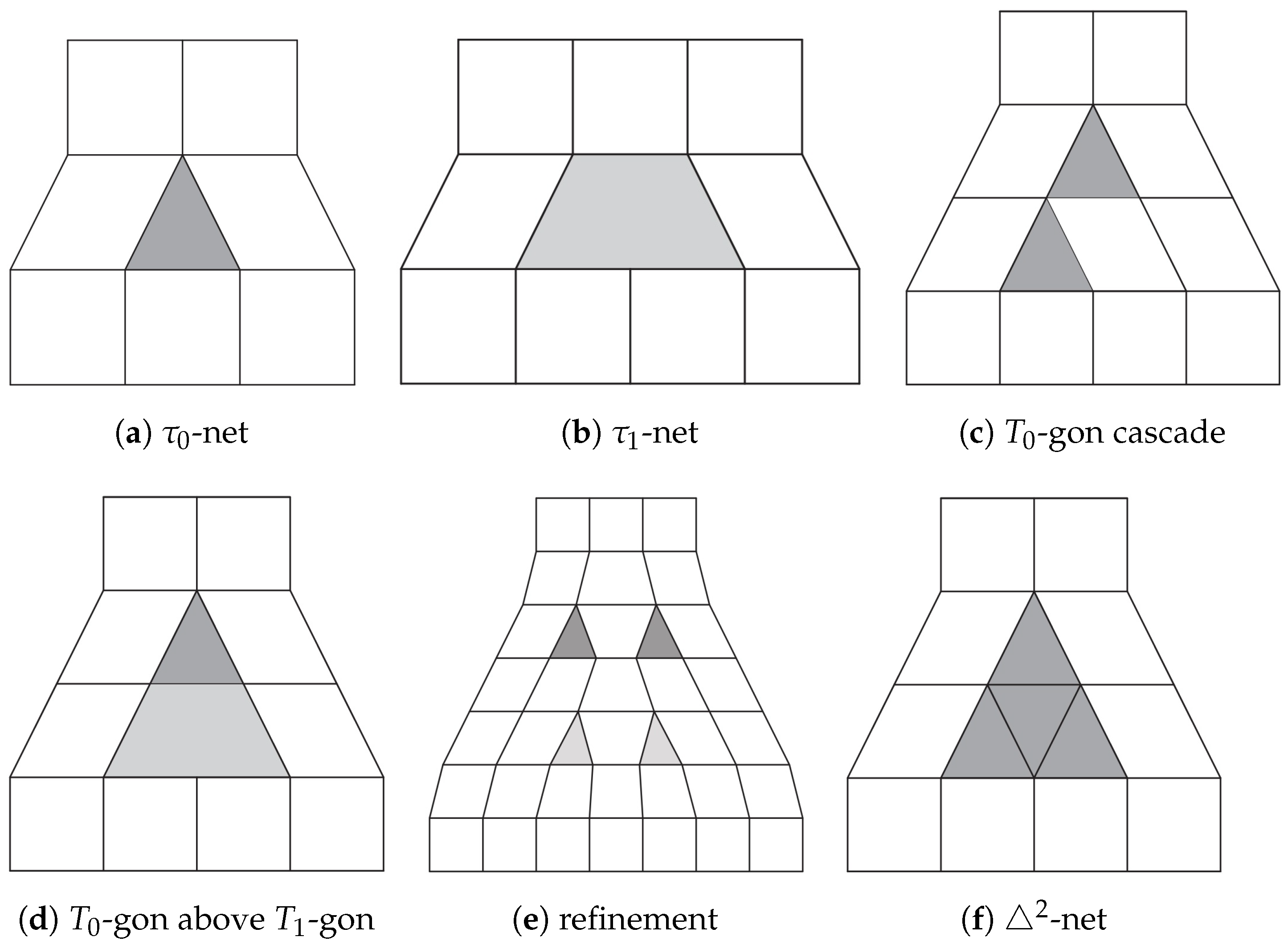
To accommodate narrower surface passages or account for less shape fluctuation, a designer can merge parallel parameter lines as illustrated in Figure 1a,b (see the gray regions). Aggressive merging in quad-meshing algorithms such as [1,2] packs the gray contraction regions too close to each other as shown in Figure 1c,d. Existing algorithms require these faces to be separated by a frame of quadrilaterals. Mitigation strategies range from ad hoc designer intervention, to an improved Doo-Sabin refinement step [3,4], to special re-meshing rules for T 0 - and T 1 -locations, [5] (see Figure 1e). The drawbacks of these mitigations are both an increase in the number of patches and a decrease in the surface quality. The surface quality suffers because to obtain the required combinatorial structure, the natural cross field (flow) of the geometry is disturbed.
The recent publication [6] presented two new fast-contracting (FC) spline constructions: FC4 and FC3. FC4 generates bi-degree surfaces (2, 4) or (2, 3), and FC3 generates bi-degree 3. Both assume that the regular quad-grid of the control net define bi-2 C 1 splines, and both use the un-isotropic 2 configuration of Figure 1f as the control net that retains the two preferred directions of the tensor-product splines. The split of the gray core is ignored and no re-meshing or refinement is required to guarantee geometric G 1 continuity of the resulting surfaces.
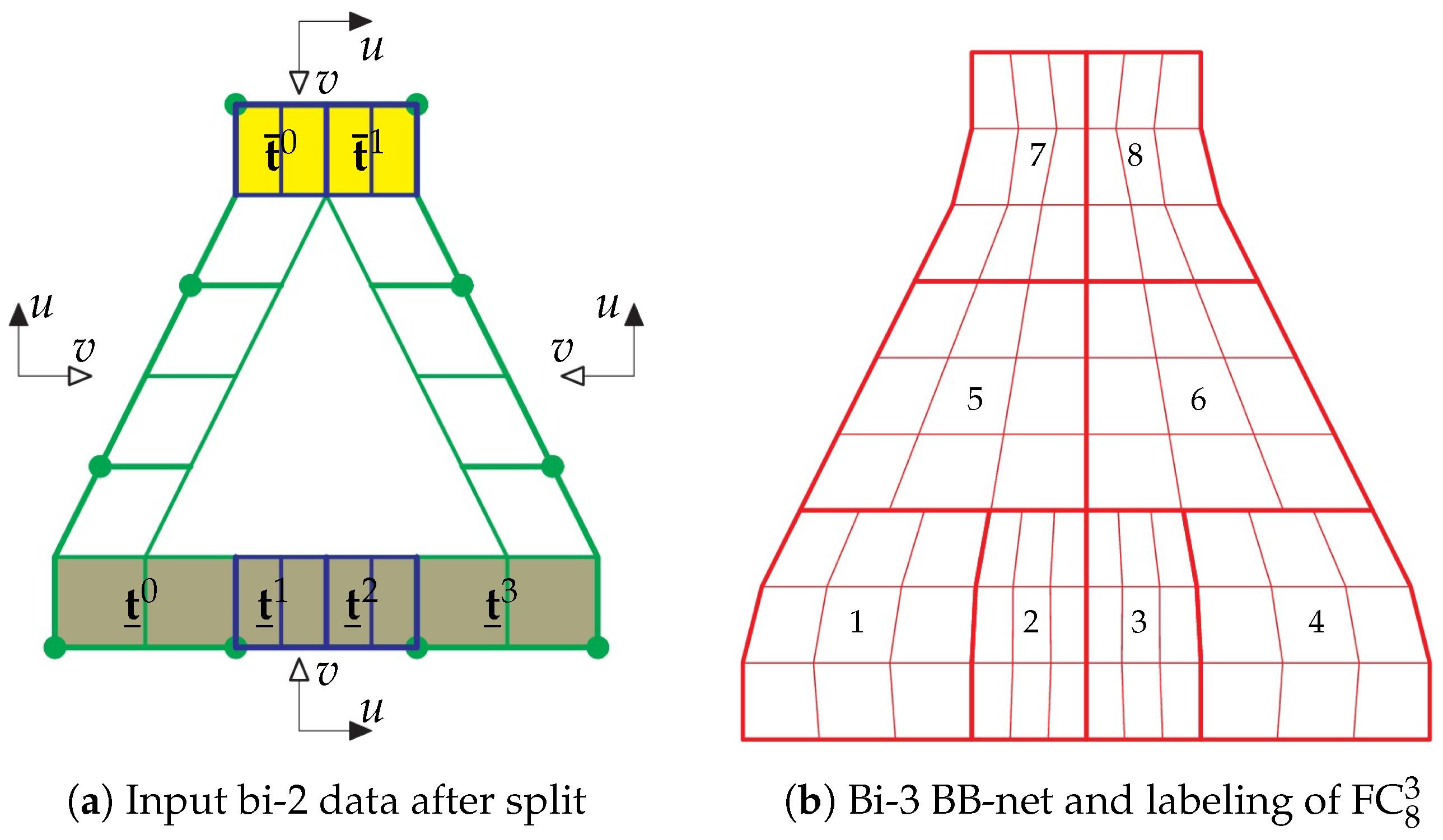
Unlike FC3, the new bi-3 construction FC 8 3 manages the transition from two (top) to four (bottom) bi-3 pieces via two internal T-junctions, and requires only the two T-junctions of the center line (see Figure 2e vs. Figure 2f). Remarkably,
  • FC 8 3 is a 8-piece bi-3 (bi-cubic) construction.
  • FC 8 3 yields improved shape compared to FC3, measured empirically with a more uniformly highlighted line distribution, and has fewer polynomial pieces, the minimal number required for a good shape.
  • The FC 8 3 formulas for generating bi-3 patches are linear in the input control net, and hence can be collected into a matrix.
  • The implementation of FC 8 3 can so be reduced to gathering the control net in a vector of points and multiplying the vector by a matrix.
The patch count can be further reduced to 7 by merging the two middle patches of FC 8 3 ; however, as will be demonstrated, this diminishes the resulting surface quality significantly.
We note that tensor product splines (NURBS) are the preferred representation in many modeling packages and degree bi-3 (bi-cubic) is the preferred degree. Catmull-Clark subdivision surfaces [7], popular in computer graphics, are also of degree bi-3 but consist of an infinite sequence of nested rings generated by recursion. More importantly, however, Catmull-Clark and bi-2 Doo-Sabin [3] subdivision rules are used for treating control net configurations with n directions equally, i.e., isoptropically, whereas FC splines retain the two preferred direction of the bivariate tensor-product splines. That is, FC splines are more general than tensor-product splines in that they allow for merging of quad strips.
After a brief literature review, Section 2 introduces the technical nomenclature and reviews the existing constructions FC3 and FC4. Section 3 introduces and derives the new 2 -net construction with explicit tables for implementation. Section 4 provides example-driven critical assessment and discussion of variants as well a comparison to FC3. For rotationally symmetric scenarios that permit regular layout or less contraction, FC 8 3 is shown to be at least as well-shaped as regular bi-2 splines and the surfaces presented in [8].
Figure 1. Contracting control net configurations: one strip contraction in (a) τ 0 -net and (b) τ 1 -net from [8,9] and two-strip contraction via (c) cascading triangles, (d) T 0 -gon + T 1 -gon and (e) refinement according to [5]; (f) 2 -net with triangulated gray core as a generalization of (c,d), see [6]. Removing from the core one inner bottom edge yields (c), removing both yields (d).
Axioms 13 00390 g001
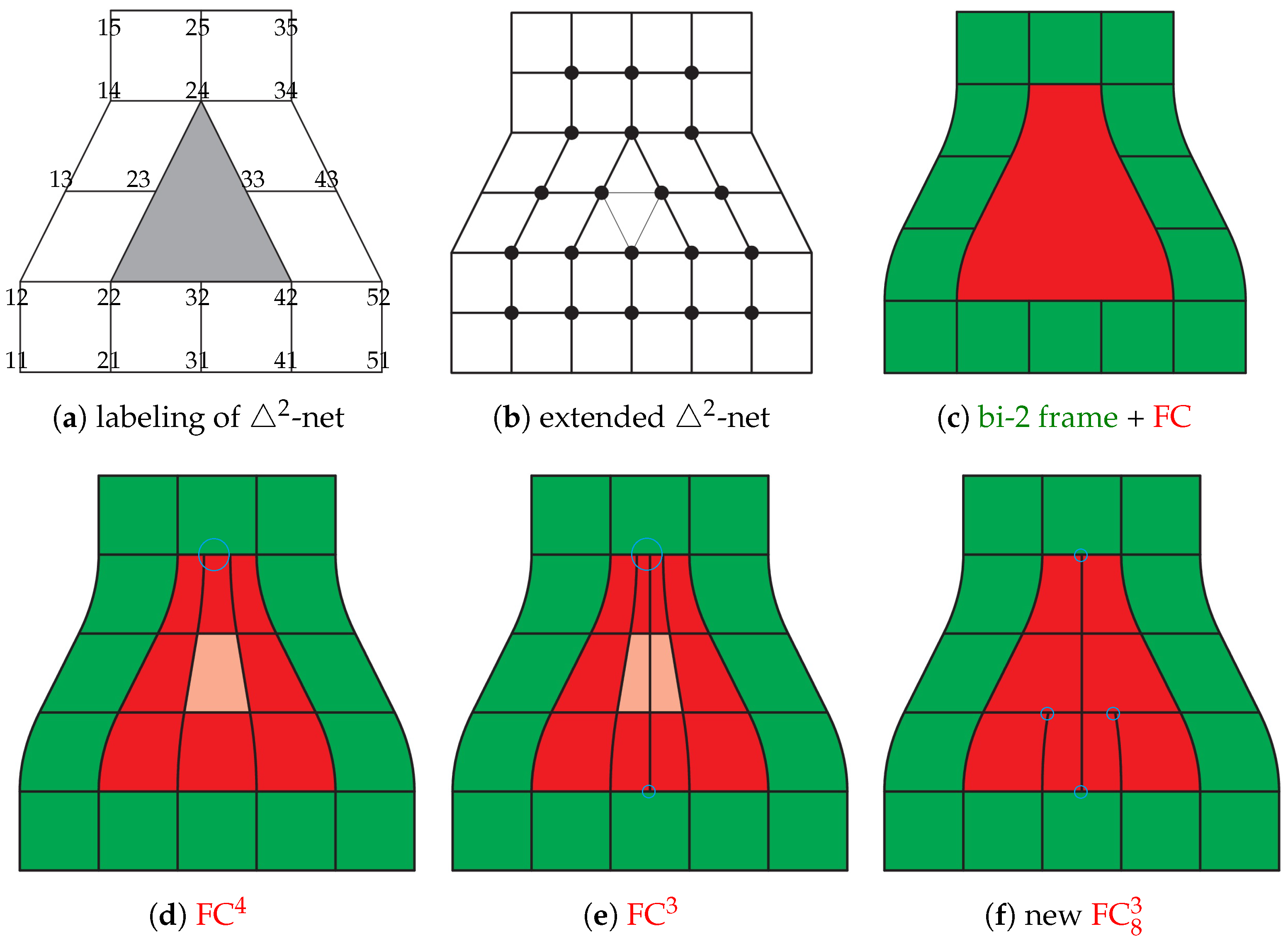
Figure 2. Rapid contraction: (a) 2 -net with 20 labels of its nodes d i j . (b) Extended 2 -net allows to produce one bi-2 frame via B-to-BB conversion as shown in (cf). Bottom row: layouts of FC4 and FC3 from [6] and FC 8 3 .
Axioms 13 00390 g002

Related Work

FC constructions assemble a finite number of polynomial pieces to join smoothly after a change of variables. Such G k constructions complement constructions for isotropic configurations such as rational multi-sided surfaces [10,11,12], and singularly parameterized surfaces. The sub-genres of singular constructions are subdivision surfaces [3,7,13,14,15], edge collapse, polar surfaces [16,17,18], and vertex singular surfaces [19,20,21,22] or rational singular constructions [23,24].
The shapes of G 2 constructions of degree bi-7 [25] or degree bi-6 [26], and lower-degree tangent-continuous splines [27,28,29,30,31,32,33] are empirically measured via highlighted line distribution [34]. FC surfaces fill irregularities in a C 1 bi-quadratic (bi-2) tensor-product surface, which is attractive since bi-2 splines have minimal bi-degree for smoothing quadrilateral meshes. Subdivision generalizations of bi-2 splines consist of an infinite sequence of nested (contracting) bi-2 polynomial surface rings. Ref. [3] has visible artifacts already in the first ring, Augmented Subdivision presented in [4] improves the shape by following a carefully chosen central guide point and polyhedral-net splines [35] combine algorithms from [8,18,36] to generalize tensor-product bi-quadratic (bi-2) splines, filling in finitely many polynomial pieces of degree at most bi-3. T-splines [37] address the merging parallel quad strips but typically serve only to refine an existing quad partition; due to their global parameterization requirement, they may not be well-defined for a given T-configuration, (see Figure 2 in [38] and Figure 6 in [39]). Alternatively, T-junctions in the control net can be associated with smooth surfaces of bi-degree ( 2 , 4 ) [9] or bi-3 [8] that result in smooth surfaces of good quality. FC 8 3 is partly motivated by the output of quad-dominant meshing algorithms such as [1,2], that introduce (fast) mesh contractions. We note that the present paper does not touch on re-meshing [40,41,42], but focuses on frequently occurring contracting configurations.

2. Control Nets, Macro-Patches, FC3 and FC4

FC 8 3 is an improvement of FC3. We therefore use the notation of [6]. Similarly to tensor-product spline control nets, the 2 nets have two distinguished directions that we refer to as ‘vertical’ and ‘horizontal’ due to their layout in Figure 2. The number of mesh lines is reduced or expanded only in the vertical direction.

2.1. Control Nets

Figure 2a displays the labels of 2 -net used for the derivation and presentation of pre-calculated data. The bottom row of Figure 2 compares the patchworks of three FC surfaces. FC4, see Figure 2d, consists of pieces of bi-degree ( 2 , 4 ) (i.e., 2 in the horizontal direction) except for a middle row of bi-degree ( 2 , 3 ) . The central, light-red patch serves as a model for the bi-3 constructions. For FC3, see Figure 2e; this central patch is degree-raised to bi-3 and split into two to keep a tensor-product structure of red macro-patch. The layout of the bi-3 pieces of FC 8 3 is shown in Figure 2f. The circles in Figure 2d–f mark the locations of T-junctions: small points to a single T-junction, to multiple T-junctions. The two T-junctions in (d) merge three strips into one. The additional T-junctions in (e) follow from the fact, proven in [6], that any C 1 bi-3 construction requires an even number of pieces, both at the bottom and the top.

2.2. Polynomial Pieces

FC 8 3 consists of tensor-product pieces of polynomial bi-degree ( d , d ) in Bernstein-Bézier form (BB-form, [43]). That is, for Bernstein polynomials B k d ( t ) : = d k ( 1 t ) d k t k , the bi-dgree 3 (bi-3) patch p is defined as
p ( u , v ) : = i = 0 3 j = 0 3 p i j B i 3 ( u ) B j 3 ( v ) , 0 u , v 1 .
With the convention that u is the parameter tracing out the horizontal direction.
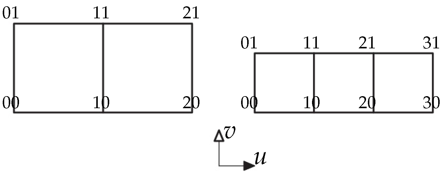
Connecting the BB-coefficients  p i j R 3 to p i + 1 , j and p i , j + 1 wherever well-defined yields the BB-net, see Figure 3. Any 3 × 3 grid can be interpreted as the control net of a uniform bi-2 spline in uniform knot B-spline form. In Figure 3, the B-spline control points are marked ∘. The B-to-BB conversion (e.g., by knot insertion) expresses the spline in bi-2 BB-form illustrated by the green BB-nets in Figure 3. Conversion of a partial sub-grid yields a partial BB-net t , called tensor-border, that defines the position and first derivatives across an edge.
The changing number of mesh lines forces a change of parameterization and hence the introduction of geometric continuity: Two polynomial pieces p , q : R 2 R 3 join G 1 along the common curve with BB-coefficients p i 0 = q i 0 if there exists a reparameterization ρ : R 2 R 2 , see, e.g., [44],
p ( u , v ) : = q ρ ( u , v ) , ρ ( u , v ) : = ( u + b ( u ) v , a ( u ) v )
v q ( u , 0 ) = a ( u ) v p ( u , 0 ) + b ( u ) u p ( u , 0 )
for scalar-valued, univariate functions a and b. In addition to the shared BB-coefficients of the common boundary, only the layers of BB-coefficients p i 1 and q i 1 of adjacent patches enter the G 1 continuity constraints. In the derivation, u-, v-directions can be assigned as convenient, but typically u is used to parameterize along the boundary and v in the orthogonal direction of the tensor-border, towards the interior or core.

2.3. Summary of FC4 and FC3

The bi-2 tensor-border frame (dark green in Figure 4a) represents first-order Hermite data. This input for all FC constructions stems from the 2 -net by B-to-BB conversion.
Figure 4 summarizes the construction of FC4. The khaki-colored bottom layer in (a) is degree-raised to bi-degree ( 2 , 4 ) and the yellow top layer is uniformly split into 3 pieces and degree-raised. The light-green left and right layers are the result of reparameterizing the left pieces t 0 , t 1 , and t 2 , and the right pieces t 3 , t 4 , t 5 of input tensor-border frame, respectively. Unconstrained BB-coefficients are marked •, and the BB-coefficients marked × are defined by C 1 extension of the central (light-red) patch. The remaining BB-coefficients are the averages of their horizontal (black and light-green) neighbor BB-coefficients.
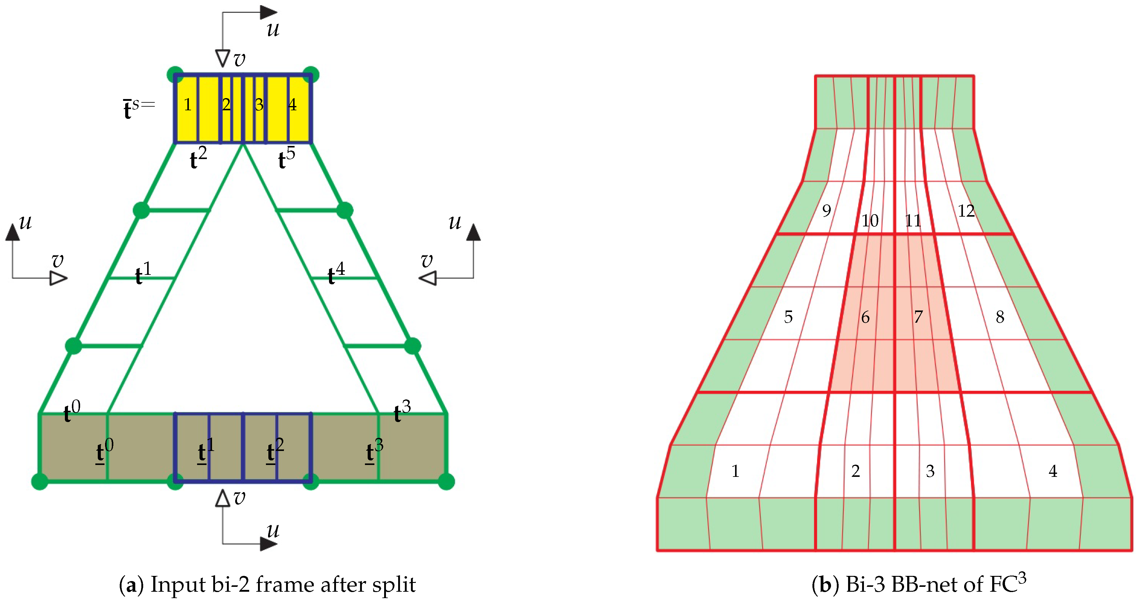
With Figure 5 providing tensor-border labels, the construction of FC3 is summarized in Figure 6. In (a), leaving t i , i = 0 , , 5 , from Figure 4a and t ̲ 0 and t ̲ 3 unchanged. t ̲ 1 and t ̲ 2 represent a uniformly split piece at the middle of the bottom frame of Figure 4a. Mimicking the bottom split, t ¯ i , i = 0 , , 3 , top split with ratio 1 : 1 2 : 1 2 : 1 . In (b), the reparameterized pieces t i , i = 0 , , 5 , t ̲ i , i = 0 , , 3 and t ¯ i , i = 0 , , 3 (light-green) are consistent at all four corners and the light-red bi-3 patches 6 and 7 represent the central light-red bi-degree ( 2 , 3 ) patch from Figure 4b, after degree-raising and split. The reparameterizations ρ s , s = 0 , 1 , 2 , ρ ̲ s , s = 0 , 1 , 2 , 3 and ρ ¯ s , s = 0 , 1 are also used in FC 8 3 construction, see Figure 5 for the labeling. Formulas (3) and (4) define the bi-3 tensor-border frame (light-green in Figure 6b) due to the symmetries ρ 3 + s : = ρ s , s = 0 , 1 , 2 .
ρ s ( u , v ) : = ( u , a s ( u ) ) , a s ( u ) : = a 0 s ( 1 u ) + a 1 s u ; t ˜ s : = t s ρ s ; [ a 0 0 , a 1 0 ] : = [ 1 , 7 9 ] , [ a 0 1 , a 1 1 ] : = [ 7 9 , 5 9 ] , [ a 0 2 , a 1 2 ] : = [ 5 9 , 1 3 ] ; t ˜ 01 s : = 1 2 3 a 0 s t 00 s + 2 3 a 0 s t 01 s , t ˜ 11 s : = 1 3 2 9 a 1 s t 00 s + 2 3 4 9 a 0 s t 10 s + 2 9 a 1 s t 01 s + 4 9 a 0 s t 11 s .
The boundary BB-coefficients t ˜ i 0 s , i = 0 , , 3 , are obtained from t i s , i = 0 , 1 , 2 by degree-raising. The remaining BB-coefficients t 21 s and t 31 are defined by the symmetry t i j s t 2 i , j s , i = 0 , 1 , 2 , j = 0 , 1 ; a i s a 1 i s , i = 0 , 1 .
The bottom reparameterizations ρ ̲ s and top reparameterizations ρ ˜ s , s = 0 , 1 , 2 , 3 , are defined by formulas
ρ ̲ s : = ( u + γ ̲ s B 1 2 ( u ) v , v ) , γ ̲ s : = ( 1 ) s + 1 9 ; ρ ¯ s : = ( u + γ ¯ s B 1 2 ( u ) v , v ) , γ ¯ s : = ( 1 ) s 3 .
Setting γ : = γ ̲ s , p : = t ̲ s , q : = t ̲ ˜ s in (4) yields explicit formulas for the BB-coefficients of the reparameterized bi-3 tensor-border t ̲ ˜ s : = t ̲ s ρ ̲ s . Setting γ : = γ ¯ s , p : = t ¯ s , q : = t ¯ ˜ s in (4) yields t ¯ ˜ s : = t ¯ s ρ ¯ s .
q 01 : = 1 3 p 00 + 2 3 p 01 , q 31 : = 1 3 p 20 + 2 3 p 21 , q 11 : = 1 9 4 9 γ p 00 + 2 9 + 4 9 γ p 10 + 2 9 t 01 + 4 9 p 11 , q 21 : = 2 9 4 9 γ p 10 + 1 9 + 4 9 γ p 20 + 4 9 p 11 + 2 9 p 21 ,
the boundary BB-coefficients q i 0 , i = 0 , 1 , 2 , 3 , are obtained from p i 0 , i = 0 , 1 , 2 , by degree-raising.

3. The FC 8 3 Construction

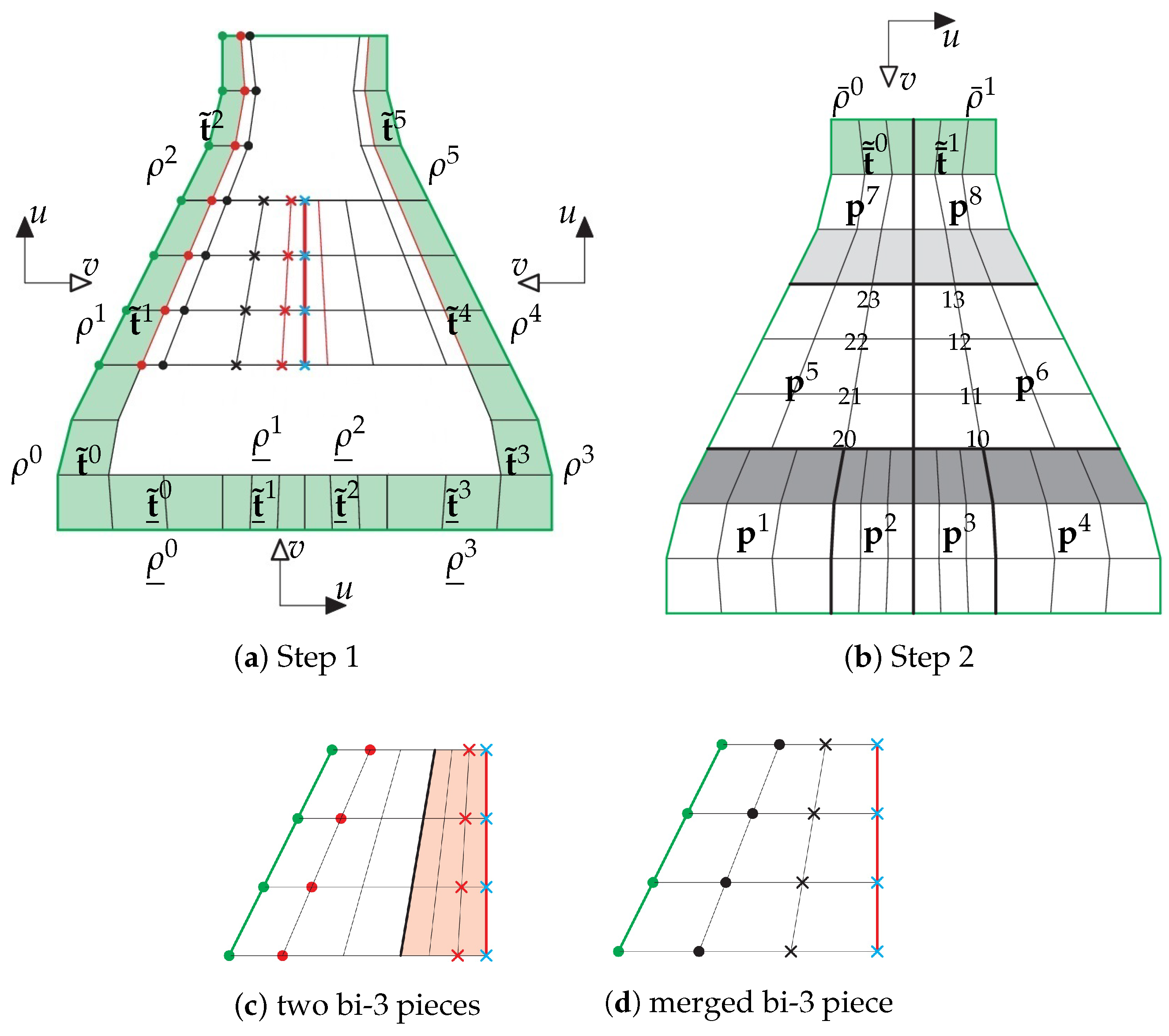
Starting with the bi-2 tensor-border frame, see Figure 7a, of FC3, cf. Figure 6a; however, anticipating the layout displayed in Figure 7b, uniformly splitting the top, we construct the bi-3 tensor-border frame (light-green in (a)) according to Section 2.3, Figure 6, and the reparameterized tensor-borders t ˜ 1 , t ˜ 2 (and analogously t ˜ 4 , t ˜ 5 ) in Figure 8a re-scaled as : = 3 2 1 2 (Hermite data: on the boundary remain unchanged). All data of p 5 in Figure 8b is displayed in Figure 8a, middle-left and again, enlarged, in Figure 8c,d. The light-red underlain piece in Figure 8c represents the bi-3 patch in Figure 6b with label 6. Leaving × unchanged, we set the BB-coefficients marked × : = 3 × 2 ×, to form the layer p 2 j 5 , j = 0 , , 3 in Figure 8b. The BB-coefficients p 1 j 6 , j = 0 , , 3 are constructed analogously. By construction, p 3 j 5 = p 0 j 6 , j = 0 , , 3 and p 3 j 5 : = 1 2 p 2 j 5 + 1 2 p 1 j 6 . On top, the re-scaled tensor-border is reparameterized by ρ ¯ 0 , ρ ¯ 1 defined in Section 2.3 yielding t ¯ 0 , t ¯ 1 , see Figure 7a. By inspection, the parameterization is consistent at the top two corners in Figure 8b. The patches p 7 and p 8 are completed by light-gray extension of patches p 5 , p 6 , see Figure 8b. The patches p s , s = 1 , , 4 , are completed by dark-gray extension of patches p 5 , p 6 and a subsequent split.
FC 8 3 expresses the BB-coefficients as affine combinations of the 2 -net nodes d . That is, with the formulas of Section 2.3, explicit formulas are available once the BB-coefficients of the central patches are known (light-red in Figure 6b). These can be gleaned from [6]; however, here, we present the explicit weights μ of formulas formulas for j = 0 , , 3 , s = 0 , , 3 (see Figure 8b).
p 2 s 5 : = i = 1 5 j = 1 2 μ i j s d i j + i = 1 4 μ i 3 s d i 3 + i = 1 3 μ i 4 s d i 4 , p 1 s 6 : = i = 1 5 j = 1 2 μ 6 i , j s d i j + i = 1 4 μ 5 i , 3 s d i 3 + i = 1 3 μ 4 i , 4 s d i 4 .
Without the loss of quality, the coefficients μ can be stated with 5 decimal accuracy and corrected by less than 0.00009 to form a partition of 1. That is, the weights μ i j s listed below are exact, not approximations of the implementation weights.
Table M s lists 10 5 μ 14 s μ 24 s μ 34 s × × μ 13 s μ 23 s μ 33 s μ 43 s × μ 12 s μ 22 s μ 32 s μ 42 s μ 52 s μ 11 s μ 21 s μ 31 s μ 41 s μ 51 s .
M 0 : = 1287 2571 1287 × × 896 38395 15479 2979 × 4441 9437 47248 13479 2358 428 1705 2561 1705 428 , M 1 : = 1952 3904 1952 × × 496 62003 25198 4364 × 6080 9877 32592 16127 3997 934 3739 5608 3739 934
M 2 : = 2448 12463 1753 × × 6449 56051 23412 2578 × 2892 12303 18821 12303 2892 828 3315 4971 3315 828 , M 3 : = 8725 38797 2475 × × 5059 32439 13689 1190 × 1674 7179 11010 7179 1674 531 2128 3188 2128 531

4. Assessments and Comparisons

One motivation of FC 8 3 was to significantly reduce the number of bi-3 patches in FC3 without overtly harming surface quality. For completeness, we also compare a FC construction composed of 7 patches with FP7, and with FF4, of the same layout as FC 8 3 , but pinning down degrees of freedom via the functional F 4 : = 0 1 0 1 i + j = 4 , i , j 0 4 ! i ! j ! ( s i t j f ( s , t ) ) 2 d s d t .

4.1. Small Local Challenge Nets

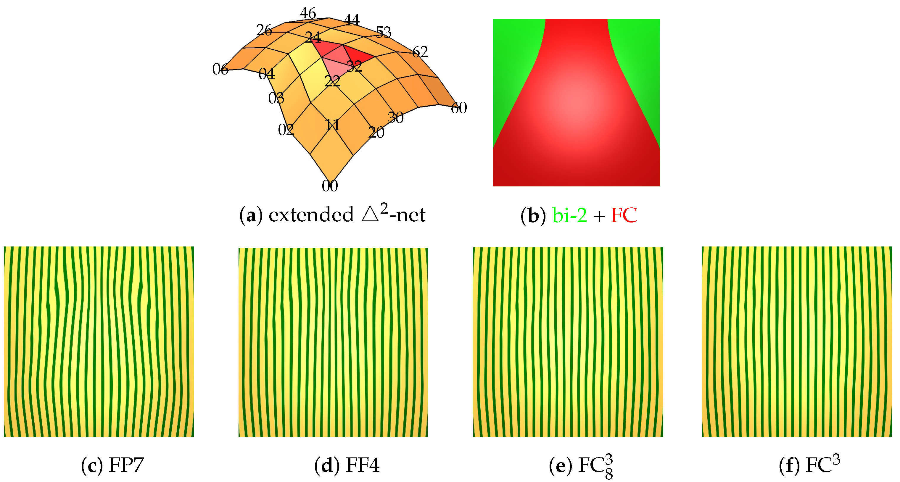
Figure 2b already introduced the 2 -net (nodes marked by •) extended by a quad frame whose outermost nodes can be of any valence. While a FC surface is fully defined by 2 -net, the extended 2 -net yields a regular B-spline bi-2 frame as in Figure 2c–f, that reveals any problems in the transition from regular to FC surface. Conversely, the restriction to the extended 2 -net avoids the need to zoom-in into area of irregularity on a large model, see, e.g., Figure 9a and emphasize problematic nets.
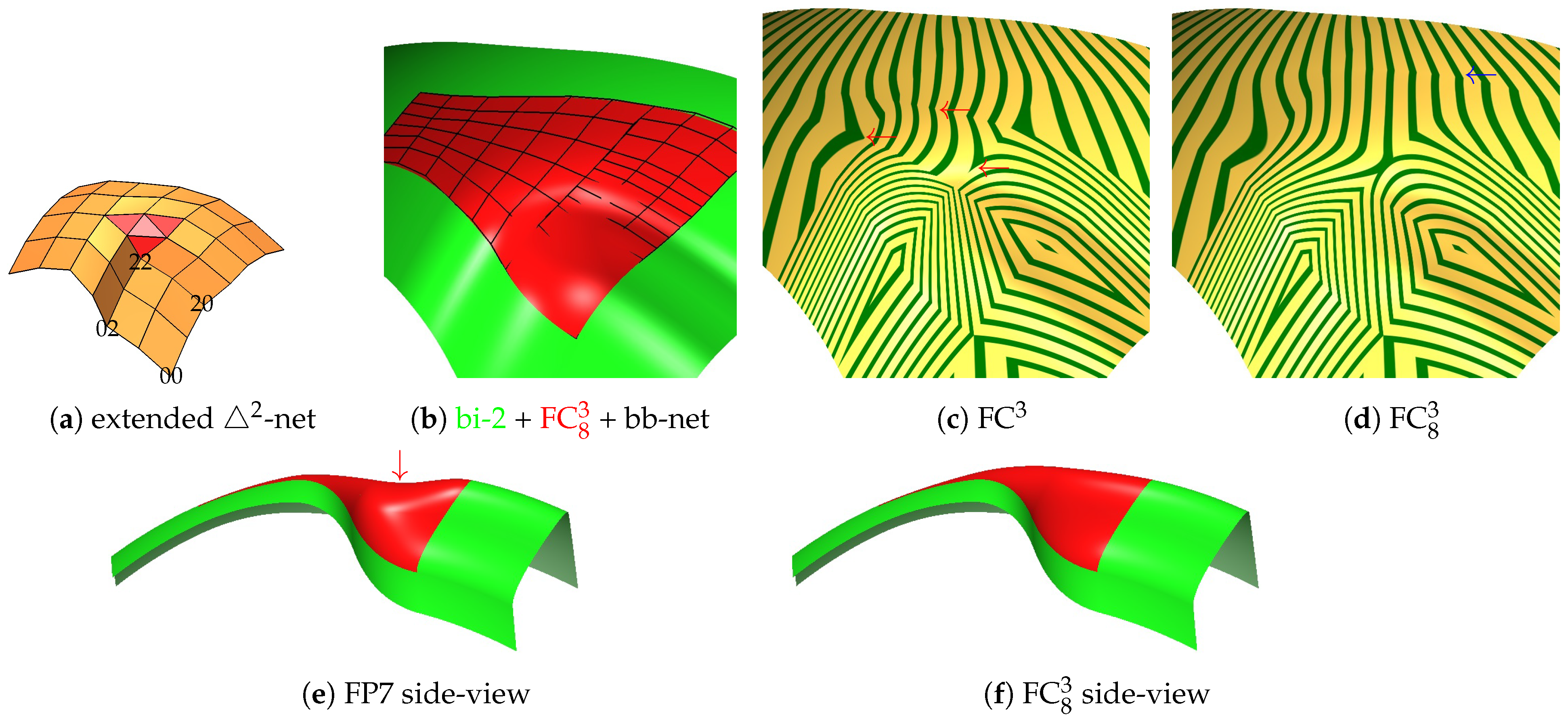
The nodes of the 2 -net shown Figure 10a are obtained from the planar layout of Figure 2b by projection onto an elliptic paraboloid. This type of control net is key when testing surfaces obtained from nets contracting as in Figure 1: a high quality surface, similar to an elliptic paraboloid within the region of Figure 10b is expected. FP7 displays undesired strong oscillation of the highlighted lines, and FF4, as well as FC 8 3 reveals no artifacts under scrutiny, justifying the subtle construction in [6]. Improving on FC3 is not expected in this specific hard configuration. However, Figure 11, Figure 12 and Figure 13 show an improvement of FC 8 3 over FC3 in the highlighted line distribution across the transition between patches 5 and 6, and 7 and 8, respectively (see Figure 6b for labels), likely due to the increased smoothness when combining the patches into one.
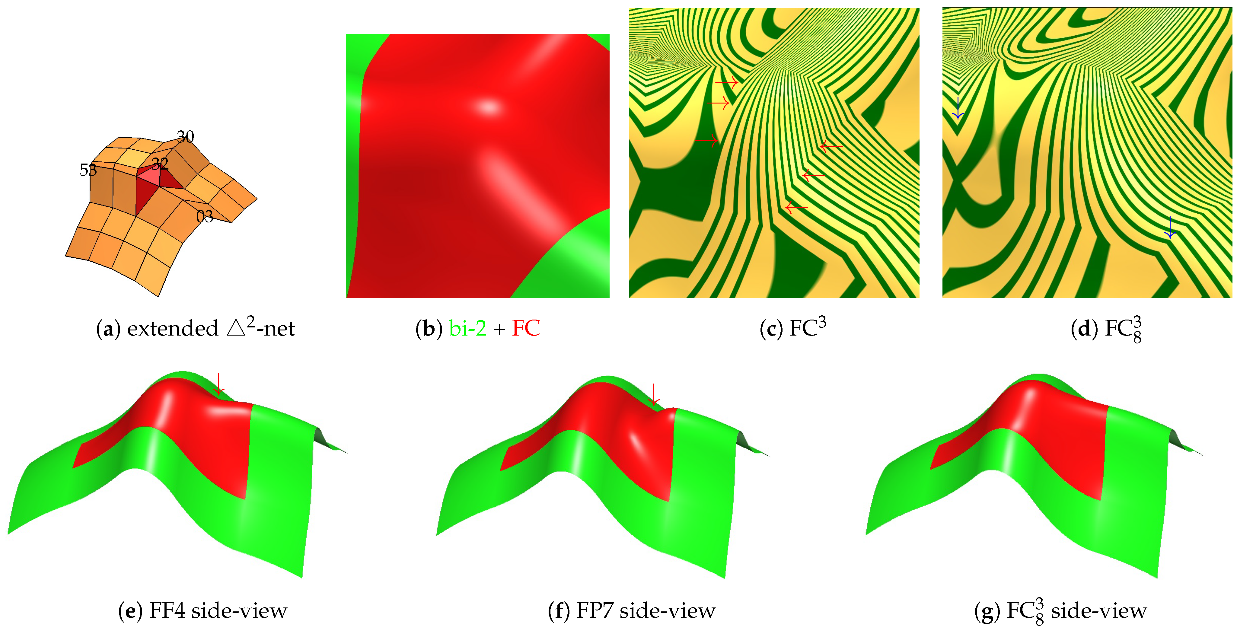
The extended 2 -net of Figure 11a is derived from Figure 10a by lifting a ‘horizontal’ row of nodes (labels i 3 , i = 0 , 5 ) and a ‘vertical’ triple ( 3 j , j = 0 , 1 , 2 ) to 32: (b) displays the region shown in (c,d). Red arrows in Figure 11c point to abrupt changes in highlighted lines for FC3 that disappear in FC 8 3 , while the in Figure 11d points to sharper turns in the FC 8 3 highlighted lines than in same location for FC3. The bottom row compares side-views revealing unexpected dips indicated by of FF4 and FP7.
The extended 2 -net of Figure 12 is derived from Figure 10a by pushing down the nodes with labels i j i , j = 0 , 1 , 2 . Red arrows in Figure 12c point to abrupt changes in highlighted lines for FC3 that disappear in FC 8 3 , while the in Figure 12d points to slightly sharper turns in the FC 8 3 highlighted lines than in the same location for FC3. The bottom row compares side-views for FC 8 3 and FP7, revealing an unwanted dip, indicated by , in FP7. Figure 13 adds a wavy 2 -net commonly occurring in automatically generated meshes. Again, FC 8 3 has a slight shape advantage over FC3 indicated by .
In summary, empirically, we see only a slight (if any) degradation of the highlighted line distribution by using fewer pieces in FC 8 3 over FC3 and an improvement of FC 8 3 over FC3 in the highlighted line distribution across the transition between the merged patches. That is, sharp turns either become considerably milder or disappear.

4.2. Large Hand-Crafted Models

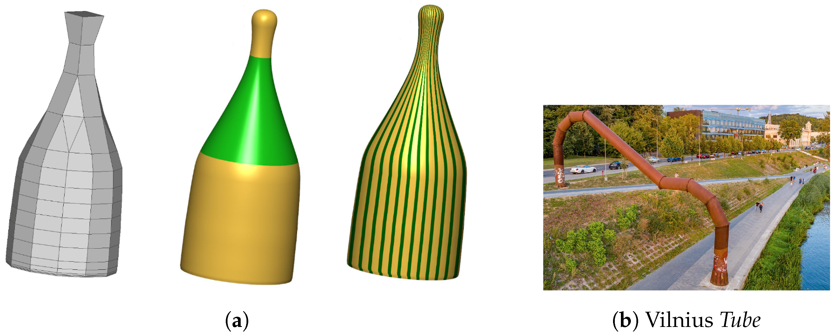
The original motivation of FC3 (FC4) was to address local challenges in re-meshing for spline surfaces. However, the solution lends itself to direct design of larger objects, e.g., to design surfaces that start with the ubiquitous shape from revolution, such as the examples in Figure 14.
Figure 15 demonstrates the design with 2 -nets. The input (a) is a mesh of revolution: the nodes in the 10 horizontal loops lie on co-axially stacked circles. The bottom 4 layers consist of 36 nodes each, the 5th has 24, the 6th and 7th have 12, the 8th layer has 8, and the top two layers have 4 nodes each. The mesh is capped by a quad face; (b) shows the surface layout: the bottom 4 layers become bi-2 patches; the 12 lower and the 4 upper 2 -nets become FC 8 3 macro-patches; the four 3-valent vertex neighborhoods at the top are covered by bi-3 patches according to [36]. While the 2 -nets overlap, their cores are sufficiently separated to build FC 8 3 macro-patches. Note that (c) contains no submesh defining a bi-2 patch. The second row zooms in on and displays the highlighted line distribution of three challenging neighborhoods: (e,f) focuses on the transition between the 12 bottom and 4 top FC 8 3 surfaces; (g,h) on the transition between the 4 top FC 8 3 and the valence 3 neighborhoods; (i,j) on the transition between the regular bi-2 patches and the 12 bottom FC 8 3 . The most noticeable changes in the highlighted lines occur where regular bi-2 C 1 splines are used, as further discussed later with respect to Figure 16c. The bottom row illustrates hand-crafted designs, whose highlighted line distributions are on par with regular bi-2 splines.
In Figure 17a, the rapid merging part of the quad strips with 2 -nets is taken from Figure 15a, while the bottom part (now four quad strips) is modified anticipating a ‘connecting tube’. The valence 5 vertices are treated with [36] to yield the smooth transitions in Figure 17b. Figure 17c,d show a design modification involving the 2 -nets.
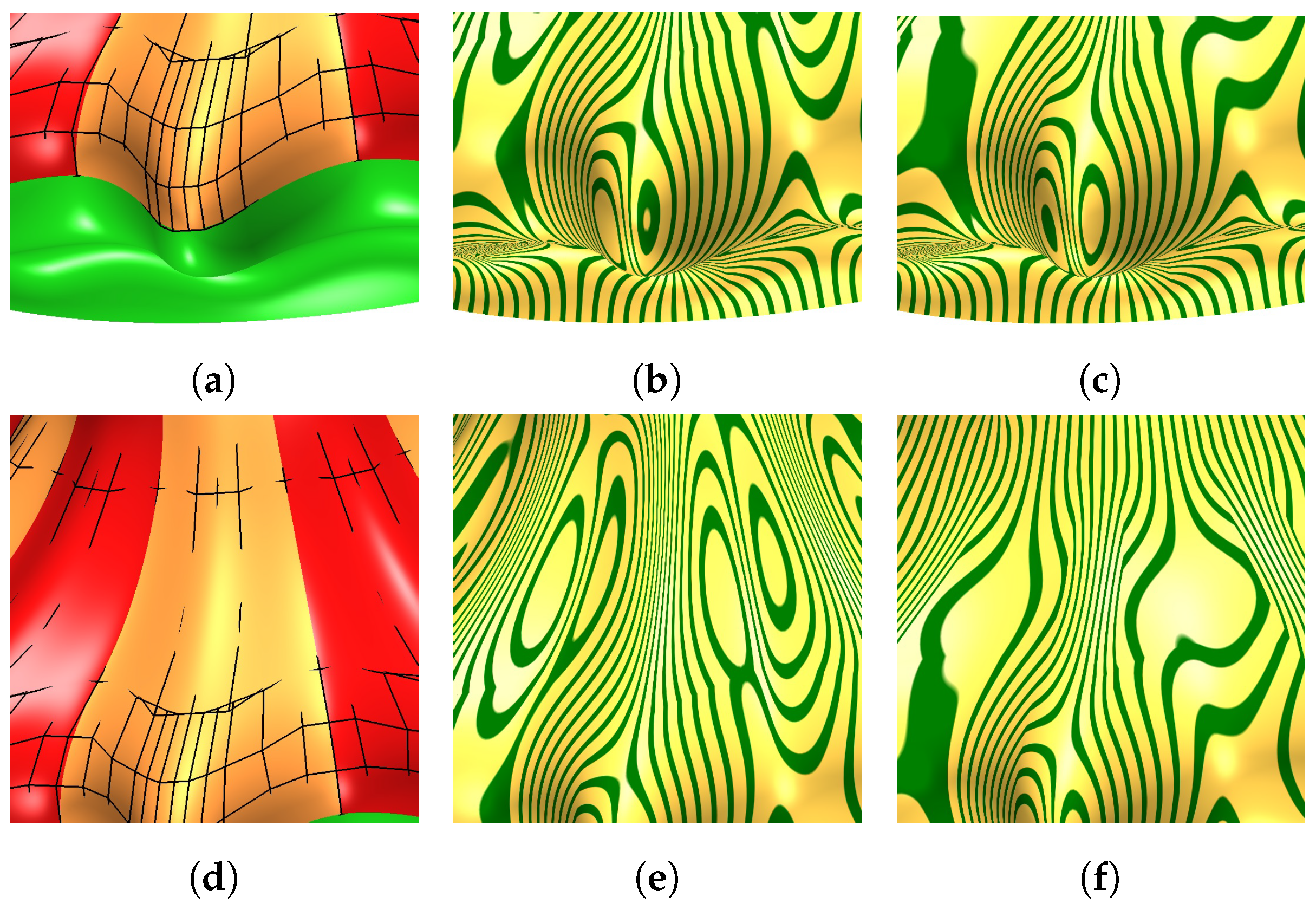
Figure 16. Detailed comparison of surfaces from Figure 15l and Figure 18j. (a,b) Figure 15l bottom; (c) Figure 18j bottom; (d,e) Figure 15l middle; (f) Figure 18j middle.
Axioms 13 00390 g016
The goal of Figure 18 is to compare FC 8 3 for 2 -nets to the less rapidly contracting bi-3 surfaces of [8] and to regular C 1 bi-2 splines for designs where any of the three options can be chosen. That is, if FC 8 3 looks no worse than its two alternatives, despite supporting rapid contraction, FC 8 3 passes the test. We recall that [8] takes as input τ 0 -nets, namely triangles with two vertices of valence 4 and one with valence 5, surrounded by one layer of quad facets. Row 1 shows surfaces created using [8], and Row 2 regular bi-2 spline surfaces. To make the corresponding surfaces as similar as possible, the 10 layers of (a) and (g) in Figure 18 lie on the same circles as for Figure 15. The main change is the number of nodes in Figure 18: in (a), layers 1 , 2 , 3 , 4 have 32, layers 5, 6 have 16, layers 7, 8 have 8 and layers 9, 10 have 4 nodes; in (g), all layers have 36 nodes. Unlike (a), in the regular mesh (g) the top is not closed: the best option in terms of simplicity and quality is to cap with 36 triangles sharing a common central vertex, i.e., a polar configuration; see [18] for the details. We omit this cap to focus on the comparison of regular splines with their counterparts based on 2 - and τ 0 -nets. (Analogously, the cap from Figure 15b and Figure 18b is omitted displaying the corresponding surfaces in Figure 18n,o.) All surfaces in Figure 15b and Figure 18b,h have the same axial symmetries and similar highlighted line distributions; see Figure 18m–o. That is, the highlighted line distributions depend on the geometry (large-scale flow) of input meshes more so than on the choice of construction. Modified surfaces can look alike as in Figure 17d and Figure 18f, or they can differ due to a different layout of τ 0 vs 2 cores (gray in Figure 1a,f); see the bottom of Figure 18d vs. Figure 15l. By contrast, the bottom of the regular bi-2 surface Figure 18j is very similar to Figure 15l; at the top the surface is less of a global shape modification than a local embossing since the corresponding layer in Figure 15a has 12, whereas Figure 18g has 36 nodes and in each case four nodes are displaced outwards (Figure 18k,l displacing by a smaller amount makes a local embossing milder; however, an effect of global modification is not achieved). Achieving the effect of FC 8 3 with the un-contracted net is a tricky challenge for a designer as is also clear if the connecting un-contracted tube ends at a single quad on the outer disk of Figure 17.
Figure 17. Design inspired by Figure 14b.
Axioms 13 00390 g017
Figure 18. Designs mimicking Figure 15 but using τ 0 -nets or regular bi-2 splines. (mo) visual equivalence of un-contracted, moderate-speed-contracted and fast-contracted surfaces. (o) corresponds to Figure 15b.
Axioms 13 00390 g018aAxioms 13 00390 g018b
Figure 16top compares the base of Figure 15l to the base of Figure 18j. The highlighted line distributions in Figure 16b,c indicate similar surface quality. Also comparing the highlighted line distribution of the mid-section, Figure 16e,f, show no clear winner. Indeed, we observe in numerous tests that the quality of FC 8 3 surfaces is no worse than the quality of regular C 1 bi-2 splines, despite the reduction in degrees of freedom.

5. Conclusions

While very specialized, the optimal treatment of rapid-contraction 2 -nets by FC 8 3 surfaces is an important building block that allows for properly adjusting the parameterization of free-form surfaces when accommodating narrow passages or a decrease in detail. Artificially comparing τ 0 -surfaces and regular bi-2 splines where such rapid contraction is not needed shows the FC 8 3 surfaces to be of equal quality and therefore to fit nicely into the polyhedral-net spline framework [35].

Author Contributions

Conceptualization, K.K. and J.P.; data curation, K.K. and K.S.-H.L.; formal analysis, K.K. and J.P.; investigation, K.K. and E.G.; project administration, J.P.; software, K.K., K.S.-H.L. and J.P.; supervision, J.P.; validation, K.K., K.S.-H.L., E.G. and J.P.; visualization, K.S.-H.L. and J.P.; writing—original draft, K.K. and J.P.; writing—review and editing, K.K., K.S.-H.L., E.G. and J.P. All authors have read and agreed to the published version of the manuscript.

Funding

Author K.L. was supported by the Informatics Institute, University of Florida, and UF Graduate School Preeminence Awards. Author E.G. acknowledges funding from The Scientific and Technological Research Council of Turkey (TUBITAK, Project No: 123F259).

Data Availability Statement

The data presented in this study are available on request from the corresponding author.

Conflicts of Interest

The authors declare no conflict of interest.

References

  1. Schertler, N.; Tarini, M.; Jakob, W.; Kazhdan, M.; Gumhold, S.; Panozzo, D. Field-Aligned Online Surface Reconstruction. ACM Trans. Graph. 2017, 36, 77:1–77:13. [Google Scholar] [CrossRef]
  2. Jakob, W.; Tarini, M.; Panozzo, D.; Sorkine-Hornung, O. Instant Field-Aligned Meshes. ACM Trans. Graph. 2015, 34, 189:1–189:15. [Google Scholar] [CrossRef]
  3. Doo, D.; Sabin, M. Behaviour of recursive division surfaces near extraordinary points. Comput.-Aided Des. 1978, 10, 356–360. [Google Scholar] [CrossRef]
  4. Karčiauskas, K.; Peters, J. Point-augmented biquadratic C1 subdivision surfaces. Graph. Models 2015, 77, 18–26. [Google Scholar] [CrossRef]
  5. Karčiauskas, K.; Peters, J. Localized remeshing for polyhedral splines. Comput. Graph. 2022, 106, 58–65. [Google Scholar] [CrossRef]
  6. Gunpinar, E.; Karčiauskas, K.; Peters, J. Splines for fast-contracting polyhedral control nets. Comput.-Aided Des. 2024, 173, 103727. [Google Scholar] [CrossRef]
  7. Catmull, E.; Clark, J. Recursively generated B-spline surfaces on arbitrary topological meshes. Comput.-Aided Des. 1978, 10, 350–355. [Google Scholar] [CrossRef]
  8. Karčiauskas, K.; Peters, J. Low degree splines for locally quad-dominant meshes. Comput. Aided Geom. Des. 2020, 83, 101934. [Google Scholar] [CrossRef]
  9. Karčiauskas, K.; Peters, J. Refinable smooth surfaces for locally quad-dominant meshes with T-gons. Comput. Graph. 2019, 82, 193–202. [Google Scholar] [CrossRef]
  10. Salvi, P.; Várady, T. Multi-sided surfaces with fullness control. In Proceedings of the Eighth Hungarian Conference on Computer Graphics and Geometry, Budapest, Hungary, 30–31 March 2016; pp. 61–69. [Google Scholar]
  11. Hettinga, G.J.; Kosinka, J. A multisided C2 B-spline patch over extraordinary vertices in quadrilateral meshes. Comput.-Aided Des. 2020, 127, 102855. [Google Scholar] [CrossRef]
  12. Vaitkus, M.; Várady, T.; Salvi, P.; Sipos, Á. Multi-sided B-spline surfaces over curved, multi-connected domains. Comput. Aided Geom. Des. 2021, 89, 102019. [Google Scholar] [CrossRef]
  13. Karčiauskas, K.; Peters, J. Point-augmented bi-cubic subdivision surfaces. In Proceedings of the Pacific Graphics 2022; Umetani, N., Vouga, E., Wojtan, C., Eds.; The Eurographics Association and John Wiley & Sons Ltd.: Hoboken, NJ, USA, 2022; Volume 41, pp. 13–23, Computer Graphics Forum. [Google Scholar]
  14. Karčiauskas, K.; Peters, J. Evolving Guide Subdivision. Comput. Graph. Forum 2023, 42, 321–332. [Google Scholar] [CrossRef]
  15. Karčiauskas, K.; Peters, J. Quadratic-Attraction Subdivision. Comput. Graph. Forum 2023, 42, e14900. [Google Scholar] [CrossRef]
  16. Myles, A.; Peters, J. C2 Splines Covering Polar Configurations. Comput. Aided Des. 2011, 43, 1322–1329. [Google Scholar] [CrossRef]
  17. Toshniwal, D.; Speleers, H.; Hiemstra, R.R.; Hughes, T.J. Multi-degree smooth polar splines: A framework for geometric modeling and isogeometric analysis. Comput. Methods Appl. Mech. Eng. 2017, 316, 1005–1061. [Google Scholar] [CrossRef]
  18. Karčiauskas, K.; Peters, J. Smooth polar caps for locally quad-dominant meshes. Comput. Aided Geom. Des. 2020, 81, 101908. [Google Scholar] [CrossRef]
  19. Peters, J. Parametrizing singularly to enclose vertices by a smooth parametric surface. In Proceedings of the Graphics Interface’91, Calgary, Alberta, 3–7 June 1991; MacKay, S., Kidd, E.M., Eds.; Canadian Information Processing Society: Toronto, ON, Canada, 1991; pp. 1–7. [Google Scholar]
  20. Reif, U. A refineable space of smooth spline surfaces of arbitrary topological genus. J. Approx. Theory 1997, 90, 174–199. [Google Scholar] [CrossRef]
  21. Nguyen, T.; Karčiauskas, K.; Peters, J. C1 finite elements on non-tensor-product 2d and 3d manifolds. Appl. Math. Comput. 2016, 272, 148–158. [Google Scholar] [CrossRef]
  22. Wei, X.; Zhang, Y.J.; Toshniwal, D.; Speleers, H.; Li, X.; Manni, C.; Evans, J.A.; Hughes, T.J. Blended B-spline construction on unstructured quadrilateral and hexahedral meshes with optimal convergence rates in isogeometric analysis. Comput. Methods Appl. Mech. Eng. 2018, 341, 609–639. [Google Scholar] [CrossRef]
  23. Gregory, J.A. Smooth interpolation without twist constraints. In Computer Aided Geometric Design; Barnhill, R.E., Riesenfeld, R.F., Eds.; Academic Press: Cambridge, MA, USA, 1974; pp. 71–88. [Google Scholar]
  24. Loop, C.T.; Schaefer, S.; Ni, T.; Castaño, I. Approximating subdivision surfaces with Gregory patches for hardware tessellation. ACM Trans. Graph 2009, 28, 151:1–151:9. [Google Scholar] [CrossRef]
  25. Loop, C.T.; Schaefer, S. G2 Tensor Product Splines over Extraordinary Vertices. Comput. Graph. Forum 2008, 27, 1373–1382. [Google Scholar] [CrossRef]
  26. Karčiauskas, K.; Peters, J. Minimal bi-6 G2 completion of bicubic spline surfaces. Comput. Aided Geom. Des. 2016, 41, 10–22. [Google Scholar] [CrossRef]
  27. Karčiauskas, K.; Peters, J. Improved shape for multi-surface blends. Graph. Models 2015, 82, 87–98. [Google Scholar] [CrossRef]
  28. Kapl, M.; Sangalli, G.; Takacs, T. Dimension and basis construction for analysis-suitable G1 two-patch parameterizations. Comput. Aided Geom. Des. 2017, 52–53, 75–89. [Google Scholar] [CrossRef]
  29. Blidia, A.; Mourrain, B.; Xu, G. Geometrically smooth spline bases for data fitting and simulation. Comput. Aided Geom. Des. 2020, 78, 101814. [Google Scholar] [CrossRef]
  30. Marsala, M.; Mantzaflaris, A.; Mourrain, B. G1-Smooth biquintic approximation of Catmull-Clark subdivision surfaces. Comput. Aided Geom. Des. 2022, 99, 102158. [Google Scholar] [CrossRef]
  31. Karčiauskas, K.; Peters, J. Bi-cubic scaffold surfaces. Comput.-Aided Des. 2022, 150, 103310. [Google Scholar] [CrossRef]
  32. Bonneau, G.P.; Hahmann, S. Flexible G1 interpolation of quad meshes. Graph. Model. 2014, 76, 669–681. [Google Scholar] [CrossRef]
  33. Karčiauskas, K.; Nguyen, T.; Peters, J. Generalizing bicubic splines for modeling and IGA with irregular layout. Comput.-Aided Des. 2016, 70, 23–35. [Google Scholar] [CrossRef]
  34. Beier, K.P.; Chen, Y. Highlight-line algorithm for realtime surface-quality assessment. Comput.-Aided Des. 1994, 26, 268–277. [Google Scholar] [CrossRef]
  35. Peters, J.; Lo, K.; Karčiauskas, K. Algorithm 1032: Bi-cubic splines for polyhedral control nets. ACM Trans. Math. Softw. 2023, 49, 7:1–7:12. [Google Scholar] [CrossRef]
  36. Karčiauskas, K.; Peters, J. Smooth multi-sided blending of biquadratic splines. Comput. Graph. 2015, 46, 172–185. [Google Scholar] [CrossRef]
  37. Sederberg, T.W.; Zheng, J.; Bakenov, A.; Nasri, A. T-splines and T-NURCCs. ACM Trans. Graph. 2003, 22, 477–484. [Google Scholar] [CrossRef]
  38. Karčiauskas, K.; Panozzo, D.; Peters, J. T-junctions in spline surfaces. ACM Trans. Graph. 2017, 36, 170:1–170:9. [Google Scholar] [CrossRef]
  39. Campen, M.; Zorin, D. Similarity maps and field-guided T-splines: A perfect couple. ACM Trans. Graph. 2017, 36, 91:1–91:16. [Google Scholar] [CrossRef]
  40. Tong, Y.; Alliez, P.; Cohen-Steiner, D.; Desbrun, M. Designing quadrangulations with discrete harmonic forms. In Proceedings of the Eurographics Symposium on Geometry Processing, Sardinia, Italy, 26–28 June 2006. [Google Scholar]
  41. Peng, C.H.; Barton, M.; Jiang, C.; Wonka, P. Exploring quadrangulations. ACM Trans. Graph. (TOG) 2014, 33, 12:1–12:13. [Google Scholar] [CrossRef]
  42. Bommes, D.; Campen, M.; Ebke, H.C.; Alliez, P.; Kobbelt, L. Integer-grid maps for reliable quad meshing. ACM Trans. Graph. (TOG) 2013, 32, 98:1–98:12. [Google Scholar] [CrossRef]
  43. Farin, G. Curves and Surfaces for Computer Aided Geometric Design: A Practical Guide; Academic Press: Cambridge, MA, USA, 1988. [Google Scholar]
  44. De Rose, T.D. Necessary and sufficient conditions for tangent plane continuity of Bézier surfaces. Comput. Aided Geom. Des. 1990, 7, 165–179. [Google Scholar] [CrossRef]
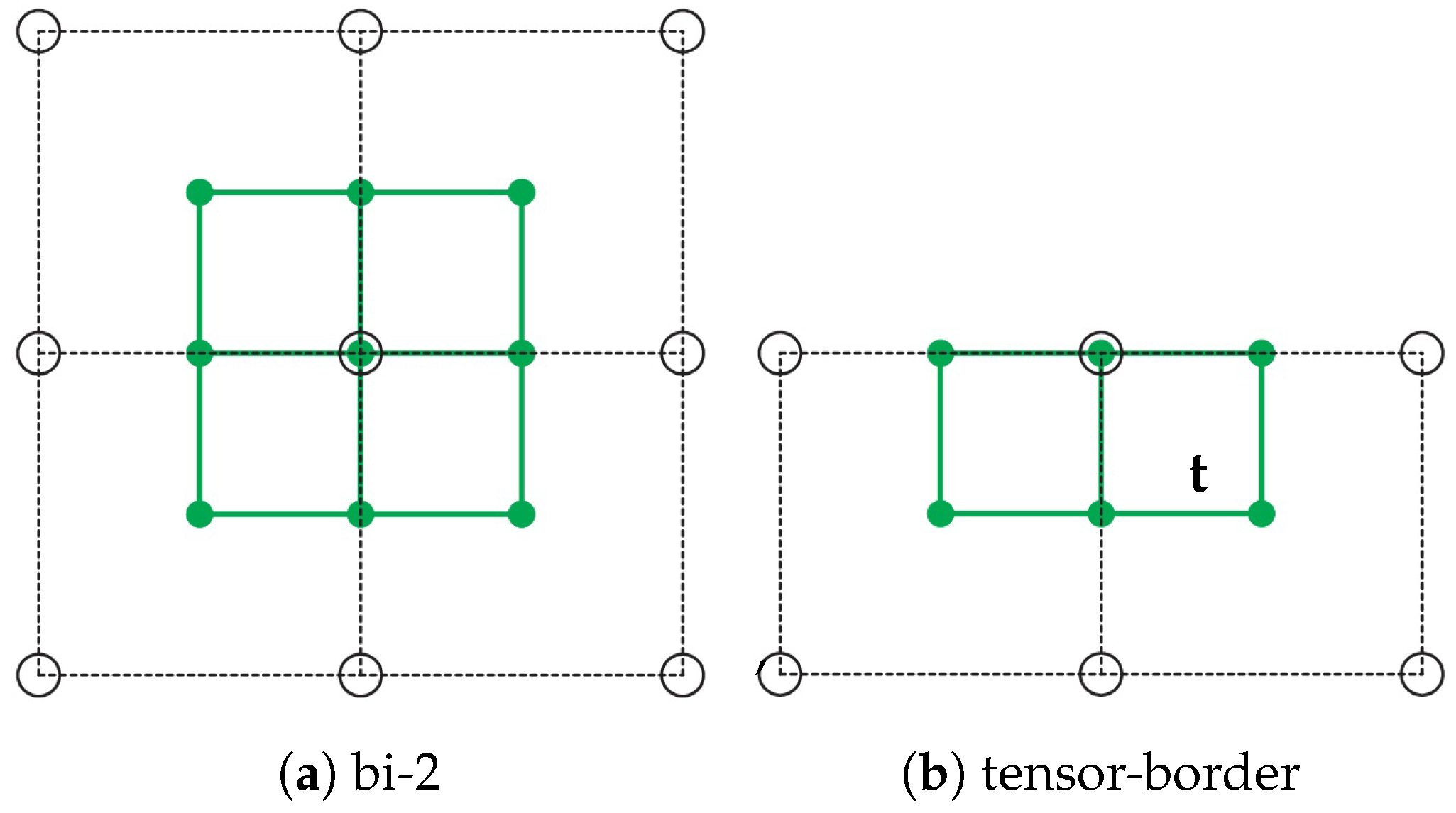
Figure 3. B-to-BB conversion and tensor-borders t as Hermite input data. Circles ∘ mark B-spline control points, solid disks mark BB-coefficients of the full patch tensor-border, respectively.
Axioms 13 00390 g003
Figure 4. FC4 review: (a) 2 -net and input bi-2 tensor-border frame obtained from 2 -net by B-to-BB conversion. (b) 3 × 3 macro-patch structure in BB-form.
Axioms 13 00390 g004
Figure 5. Labeling of left—bi-2 tensor-border; right—reparameterized bi-3 tensor-border.
Axioms 13 00390 g005
Figure 6. FC3: (a) The input bi-2 frame is split (see blue top, bottom). The local u-v-coordinate systems of the tensor-borders are shown. (b) Layout of patches and BB-nets of FC3.
Axioms 13 00390 g006
Figure 7. FC 8 3 : (a) The bi-2 tensor-border frame required for FC 8 3 coincides with the frame in Figure 6a except at the top (yellow) that is uniformly split into two pieces. (b) BB-net and labeling of the FC 8 3 macro-patch.
Axioms 13 00390 g007
Figure 8. Derivation of the FC 8 3 macro-patch construction and hence of the matrix that defines FC 8 3 . Once derived, the implementation of FC 8 3 is just a matrix multiplication. The left and right BB-coefficients and × in (c) are preserved in (d).
Axioms 13 00390 g008
Figure 9. 2 -nets arising in quad-dominant meshing ‘in the wild’. Here, FC 8 3 is green. Models from www.quadmesh.cloud/Thingi10K.
Axioms 13 00390 g009
Figure 10. Comparing FC 8 3 to variants FP7 and FF4, and to its predecessor FC3. (a) Labels of extended 2 -net, see also Figure 2a. The highlighted line distribution improves from (cf).
Axioms 13 00390 g010
Figure 11. Comparing FC 8 3 to variants FP7 and FF4 for ridge preservation.
Axioms 13 00390 g011
Figure 12. Comparing FC 8 3 to FP7 and FC3 for step-like transition. (b) Area of highlighted line distribution in (c,d).
Axioms 13 00390 g012
Figure 13. Comparing FC 8 3 to FC3 on wave-like input.
Axioms 13 00390 g013
Figure 14. Natural occurrence of 2 -nets in design. (a) FC 8 3 is green. (b) Modern art installation.
Axioms 13 00390 g014
Figure 15. Overlapping 2 nets. (c) shows the sub-net of (a) that consists entirely of overlapping 2 -nets. That is, the surface in (d) consists entirely of FC 8 3 macro-patches.
Axioms 13 00390 g015
Disclaimer/Publisher’s Note: The statements, opinions and data contained in all publications are solely those of the individual author(s) and contributor(s) and not of MDPI and/or the editor(s). MDPI and/or the editor(s) disclaim responsibility for any injury to people or property resulting from any ideas, methods, instructions or products referred to in the content.