Article

Application of Whale Optimization Algorithm Based FOPI Controllers for STATCOM and UPQC to Mitigate Harmonics and Voltage Instability in Modern Distribution Power Grids

by
Mohamed Metwally Mahmoud
1,*,
Basiony Shehata Atia
2,
Yahia M. Esmail
3,
Sid Ahmed El Mehdi Ardjoun
4,
Noha Anwer
5,
Ahmed I. Omar
6,*,
Faisal Alsaif
7,
Sager Alsulamy
8 and
Shazly A. Mohamed
9
1
Electrical Engineering Department, Faculty of Energy Engineering, Aswan University, Aswan 81528, Egypt
2
Field Service Engineer at Rapiscan Systems, 2805 Columbia St, Torrance, CA 90503, USA
3
Ministry of Electricity and Renewable Energy, Cairo 222, Egypt
4
IRECOM Laboratory, Faculty of Electrical Engineering, Djillali Liabes University, Sidi Bel-Abbes 22000, Algeria
5
Electrical Power and Machines Engineering Department, The High Institute of Engineering and Technology, Luxor 85842, Egypt
6
The Higher Institute of Engineering at El-Shorouk City, El-Shorouk Academy, Cairo 11837, Egypt
7
Department of Electrical Engineering, College of Engineering, King Saud University, Riyadh 11421, Saudi Arabia
8
Energy & Climate Change Division, Sustainable Energy Research Group, Faculty of Engineering & Physical Sciences, University of Southampton, Southampton SO16 7QF, UK
9
Department of Electrical Engineering, Faculty of Engineering, South Valley University, Qena 83523, Egypt
*
Authors to whom correspondence should be addressed.
Axioms 2023, 12(5), 420; https://doi.org/10.3390/axioms12050420
Submission received: 27 February 2023 / Revised: 19 April 2023 / Accepted: 21 April 2023 / Published: 26 April 2023
(This article belongs to the Special Issue Fractional-Order Equations and Optimization Models in Engineering)

Abstract

:
In recent modern power systems, the number of renewable energy systems (RESs) and nonlinear loads have become more prevalent. When these systems are connected to the electricity grid, they may face new difficulties and issues such as harmonics and non-standard voltage. The proposed study suggests the application of a whale optimization algorithm (WOA) based on a fractional-order proportional-integral controller (FOPIC) for unified power quality conditioner (UPQC) and STATCOM tools. These operate best with the help of their improved control system, to increase the system’s reliability and fast dynamic response, and to decrease the total harmonic distortion (THD) for enhancing the power quality (PQ). In this article, three different configurations are studied and assessed, namely: (C1) WOA-based FOPIC for UPQC, (C2) WOA-based FOPIC for STATCOM, and (C3) system without FACTS, i.e., base case, to mitigate the mentioned drawbacks. C3 is also considered as a base case to highlight the main benefits of C1 and C2 in improving the PQ by reducing the %THD of the voltage and current system and improving the systems’ voltage waveforms. With C2, voltage fluctuation is decreased by 98%, but it nearly disappears in C1 during normal conditions. Additionally, during the fault period, voltage distortion is reduced by 95% and 100% with C2 and C1, respectively. Furthermore, when comparing C1 to C2 and C3 under regular conditions, the percentage reduction in THD is remarkable. In addition, C1 eliminates the need for voltage sag, and harmonic and current harmonic detectors, and it helps to streamline the control approach and boost control precision. The modeling and simulation of the prepared system are performed by MATLAB/Simulink. Finally, it can be concluded that the acquired results are very interesting and helpful in the recovery to the steady state of wind systems and nonlinear loads, thereby increasing their grid connection capabilities.

1. Introduction

A. 
Motivation and Background 
Power quality (PQ) challenges and their remediation are now a priority for transmission system operators. PQ issues arise due to many causes such as nonlinear loads (NLs), transient faults [1,2], and the installation of renewable generators. This needs PQ improvement, which helps to extend the equipment’s life cycle as well as increase the supply reliability for supplying critical loads in the electric system [3,4,5]. The use of power electronic components (PECs) can cause technical problems for PQ, such as grid voltage dips and swells, power surges, notches, spikes, flicker, harmonics, real and reactive power deviations, and imbalanced voltage [6,7]. PQ is defined as “any fault or quality degradation of voltage, current, or frequency that causes inappropriate equipment performance or operational error” [7].
PQ issues cost the EU more than USD 200 billion every year, while the USA spends USD 30 billion per year to address such concerns [8,9]. The classification of PQ concerns is shown in Figure 1 [6]. The rapid expansion of NLs, photovoltaic systems, and wind energy (WE) systems causes harmonic distortion in branch currents, which results in harmonic voltage distortion in modern electric power systems (EPSs) [7,10]. The basic goal of any EPS is to deliver a continuous sinusoidal voltage with balanced sinusoidal currents of constant magnitude and frequency. The IEC and IEEE have outlined several PQ standards to achieve PQ standardization, which are presented in Table 1 [11].
Wind energy has made more inroads in modern EPSs because it does not give off any dangerous gases such as CO2 [12,13]. The global wind report for 2019 shows that WE output is growing, with a total installed capacity of 650 GW and wind additions surpassing 60 GW. More than 3,41,320 wind turbines (WTs) are currently operational around the world [14]. There are numerous challenges when a WE system is combined with an EPS, such as variations in both output power and voltage. It was found that the impact on EPS dynamic actions is significantly different between fixed and variable speed WTs, because of their distinct principles of operation. Due to various advantages, such as simple and sturdy construction, low maintenance, low cost, and self-starting nature, squirrel cage induction generators (SCIGs) are considered to generate wind power in our study [15,16]. A comparison of four WT generators in terms of their capability of grid stability is displayed in Table 2.
B. 
Literature Overview 
The use of passive filters for harmonic cancellation and reactive power compensating has been widely discussed. Later, application decreased due to several notable drawbacks, including continual compensatory performance, huge size, and resonance [17]. Active power filters (APFs) are becoming more popular now since they function better than passive filters [18]. They often generate an identical number of harmonics when compared to a load with a 180° phase shift. These harmonics are fed into the PCC, and the nonlinear load current harmonics are consequently reduced in sinusoidal supply [19]. The APF family can be integrated into the shunt, series, and shunt + series configurations such as STATCOM, dynamic voltage restorer (DVR), and unified power quality conditioner (UPQC), respectively, to mitigate various PQ issues [20,21,22].
In power systems, STATCOM can improve the power factor, damping power oscillations, control of voltage flicker and reactive power, and fast dynamic response based on applied switches and controllers; thus, there is no need for additional components [23]. STATCOM is utilized to increase EPS stability and performance since it outperforms the static var compensator in terms of performance and transient response, as presented in [24]. The layout for PQ improvement, as well as the varieties of STATCOM controllers, were discussed in [25,26]. A PID-based STATCOM was used to improve stability in grid-tied WTs but NLs were not considered in [27,28]. References [29,30] discussed how and why the PQ in a hybrid EPS can be enhanced using STATCOM. The development of PQ using new STATCOM approaches is progressing hour-by-hour, as mentioned in [31]. The voltage sag and swell of STATCOM can be easily regulated using the sinusoidal PWM method, which is becoming increasingly popular [32].
The UPQC is thought to be the best instrument for protecting critical and key loads from voltage- and current-based PQ issues [33,34]. Reference [7] gives a detailed analysis of the UPQC and its application in modern EPSs. In UPQCs, the series APF alleviates voltage quality disruptions such as harmonics, and over- and under-voltage, while the shunt APF alleviates current disruptions such as current harmonics and controls the DC bus to ensure the adapting efficiency of the system [35]. The literature [36] presents a survey on how to classify an APF based on its kVA rating, speed of reaction, circuit architecture, system parameter adjustment, and control mechanisms. Another study [37] analyzes topologies, setups, compensation approaches, and recent advancements in the field of UPQCs, as well as the application of UPQCs to increase PQ and system dependability. Several techniques are used to find the optimal place for the UPQC in the EPS to reduce power loss and improve the system’s performance. The UPQC can also regulate the flow of active power, reactive power, and voltage-independent power in real time [38]. The UPQC is gaining popularity over STATCOM because it can improve low- and high-voltage ride-through (L\HVRT) better than STATCOM [39,40].
The smart load in [41] was used to show and analyze only the PQ problems, and there was no adequate investigation in this regard, so the PQ problems were not solved. The authors in [42] presented only a comprehensive review linking the smart grid (SG) to solar energy to assess the contained harmonics and did not provide any options for the PQ problems. The author of [43] addressed only the harmonics of the UPQC system and did not provide a detailed design or investigation of the issue. The author only reviewed some PQ problems in his review articles [44,45,46]. Table 3 summarizes the main findings of many recently published papers in the PQ research area. The DQ detection scheme and PI, BBC, fuzzy, optimized PI, and hysteresis controllers for control systems are used in the majority of the existing studies and are included in Table 3. Furthermore, the disadvantages of those systems are already mentioned.
C. 
Contributions 
Our research provides a complete and detailed analysis study to solve the PQ problems in the studied system, in which PQ is the main factor in modern EPSs. Furthermore, this research is a comprehensive guide to improving the PQ and stability in the modern EPS using a developed STATCOM and UPQC under different operating conditions: NLs, transient three-phase faults, and WE-sourced higher penetration. This paper studies three configurations called: C1—whale optimization algorithm (WOA) based fractional-order proportional-integral controller (FOPIC) for UPQC; C2—WOA-based FOPIC for STATCOM; and C3—system without FACTS under three scenarios (NLs (S1), 42% penetration of wind energy (S2), and three-phase fault (S3), where they cause problems in PQ injected to the grid. The studied scenarios cause technical-economic damage that negatively affects the performance of the PCC bus. The main contributions of this study compared to previous works are summarized as follows:
  • A new WOA-FOPIC-based robust control was developed for the STATCOM and UPQC to improve their dynamic response, stabilize the PCC bus voltage, and reject harmonics of the current and voltage at this bus.
  • The proposed controller for the UPQC and STATCOM can risk mitigating unstable voltage and harmonics without the need for detector tools in the UPQC, which effectively reduces the UPQC cost with a less complex design.
  • The proposed configurations can solve PQ problems such as voltage distortions and minimize harmonics of the current and voltage at the PCC to acceptable levels under regular and irregular conditions (S1, S2, and S3), thereby improving EPS reliability.
  • The application of STATCOM and the UPQC overcomes 98% and 100% of the voltage fluctuation, respectively, during S1 and S2, and during S3 95% and 100% of the voltage fluctuation is overcome.
  • The UPQC is superior to STATCOM in ensuring the system is more reliable, especially during short-circuit faults and compared with recently published works.
  • Finally, it can be concluded that both C1 and C2 enable the high penetration scenarios of the WE source, NLs, and achieving FRT capability.
D. 
Paper Organization 
This work is presented as follows: Section 2 explores the system description and modeling. Section 3 and Section 4 present the performance and modeling of the proposed STATCOM and UPQC tools. In addition, a comparison between them is performed to show their benefits and capabilities in mitigating PQ problems. Section 5 provides comprehensive discussions of the obtained simulation results. Section 6 concludes the points drawn from this study.

2. System Description

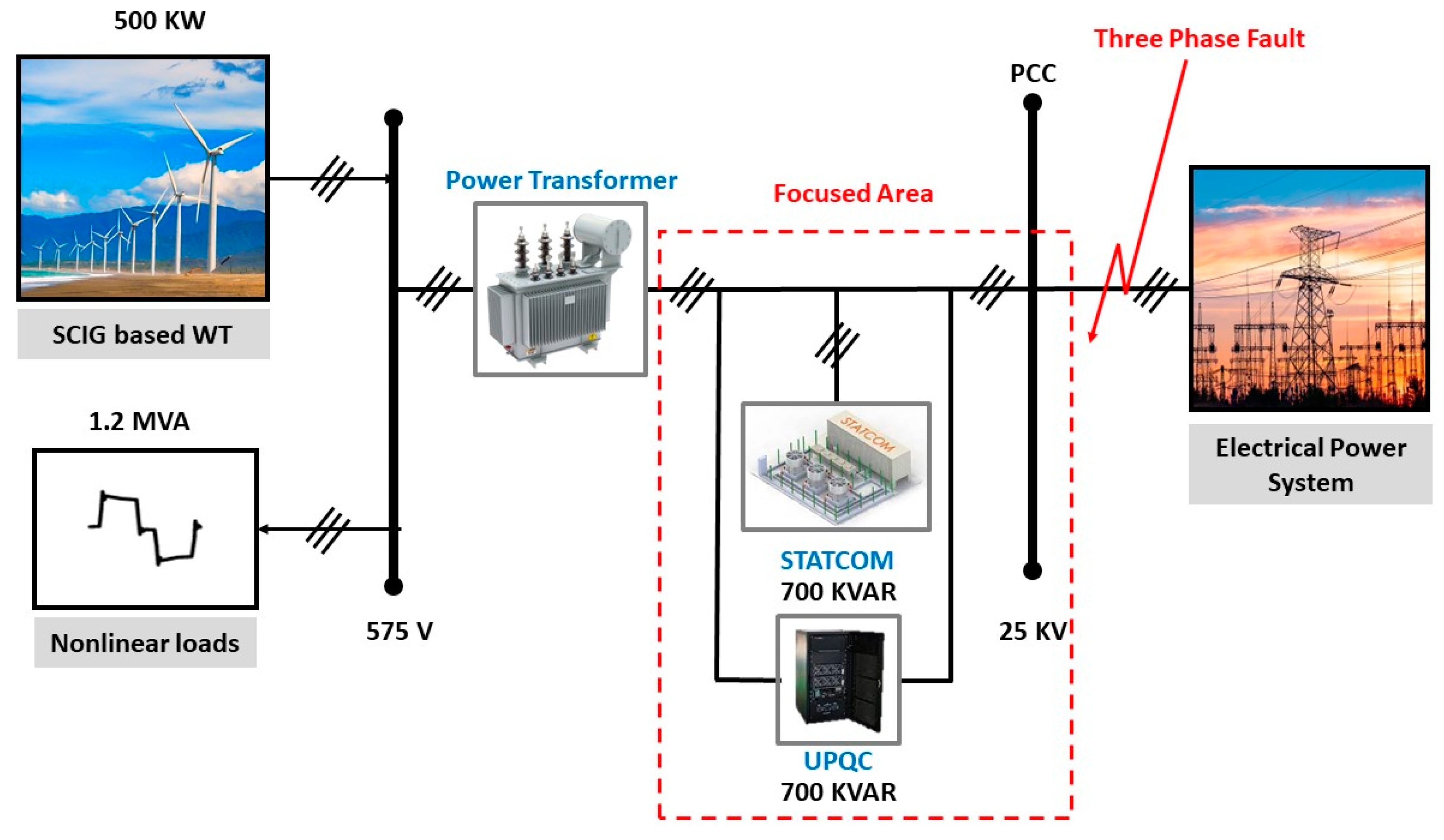
The proposed configuration is a connection of the WT system and NL to the EPS through a power transformer with the integration of STATCOM and UPQC, as depicted in Figure 2. The WT system uses a SCIG due to its merits compared with other types. Modeling of WT and SCIG are presented in this section to help us in analyzing the behavior of the investigated WE system. The most prominent PQ problems that arise from connecting the WT to the SG are voltage fluctuations and harmonics, which are verified later. To evaluate the effectiveness of the STATCOM and UPQC technologies, three operational scenarios are chosen. In the first scenario, the EPS is connected to S1, which represents several SG loads, while in the second situation, the EPS is connected to S2, which is widely dispersed across SGs. Finally, the third scenario addresses the capability of FACTS tools to overcome transient faults and maintain the stability of the EPS.

2.1. Modeling of WT

The modeling of WTs has been discussed in detail in [58]. In the equation below, Cp is the coefficient of performance, which is related to β (blade pitch angle) and λ (tip speed ratio). For the SCIG, Cp is specified by Equation (1):
C p λ , β = 0.5176 116 λ i 0.4 β 5 exp 21 λi + 0.0068 λ
1 λ i = 1 λ + 0.08 β 0.035 β 3 + 1
λ = ω m R V w i n d
Equation (4) shows the turbine’s mechanical output power, where ρ is the air density, A is the turbine swept area, and Vwind is the wind speed:
p m = 0.5 c p ρ A V w i n d 3
The value of ω m can be obtained from Equation (3):
T t u r = P m ω m
T t u r = J e q d ω m d t + B e q . ω m + T e
The variables T t u r , J e q , B e q , and T e are turbine torque, total equivalent inertia of the turbine, the damping coefficient, and the electromagnetic torque of the generator, respectively. The modeling of WTs is shown in Figure 3.

2.2. Modeling of SCIG

A fourth-order model describes the dynamic model of the SCIG according to the equations below [58]:
V q s = R s I q s + P λ q s + ω λ d s
V d s = R s I d s + P λ d s ω λ q s
V q r = R r I q r + P λ q r + ω ω r λ d r = 0
V d r = R r I d r + P λ d r ω ω r λ q r = 0
i d s i q s i d r i q r = 1 _ D 1   .   L r 0 0 L r L m 0 0 L m L m 0 0 L m L s 0 0 L s   .   λ d s λ q s λ d r λ q r
λ d s = ( V d s R s I d s + ω λ q s ) / S
λ q s = ( V q s R s I q s ω λ d s ) / S
λ d r = ( V d r R r I d r + ω ω r λ q r ) / S
λ q r = ( V q r R r I q r ω ω r λ d r ) / S
D 1 = L s L r L m 2
T e = 1.5 P ( I q s λ d s I d s λ q s )
The parameters used in modeling are voltage (V), current (I), resistance (R), number of poles (P), rotor angular speed ( ω r ), flux linkage (λ), electromagnetic torque ( T e ), and inductance (L). The sub-indexes r and s stand for rotor and stator, respectively.

3. Modeling and Control of Proposed Developed Systems

3.1. Modeling and Control Structure of Investigated STATCOM System

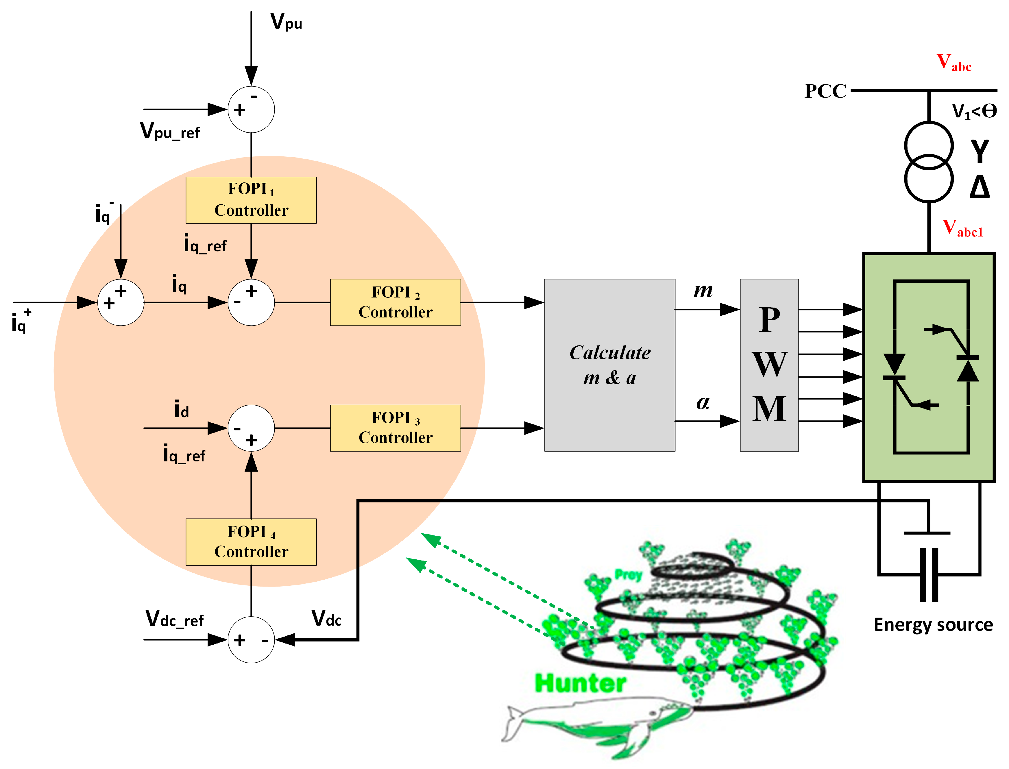
STATCOM units can supply Q to the EPS with a very fast response, which can be utilized to enhance voltage quality and mitigate other PQ disruptions in the EPS. These technologies can also improve the power grid’s efficiency and overall stability. It is a shunt reactive compensator that may absorb or generate Q in the EPS [59]. Figure 4 illustrates its identical circuit with the proposed control method. It transmits P and Q to the EPS, and the transmitted power is managed via the firing angle (α) and modulation index (m) of the pulse width modulation (PWM) of the voltage source converter (VSC).
The equations for calculating STATCOM and VSC in the three-phase structure are as follows:
L d i a d t = R I a + V a V a 1
L d i b d t = R I b + V b V b 1
L d i c d t = R I c + V c V c 1
where the system currents are Ia, Ib, and Ic. Va1, Vb1, and Vc1 are the inverter’s output voltages, while Va, Vb, and Vc are the PCC voltages. In addition, R and L are the equivalent resistance and inductance for the power transformer, respectively.
The following is a d-q frame representation of the three-phase parameters:
L d i d d t = R I d + ω L I q V d V d 1
L d i q d t = R I q + ω L I d V q V q 1
The d- and q-axis voltages of the grid and the STATCOM are represented by the symbols Vd, Vd1, Vq, and Vq1, and ω is the synchronous angular speed of the fundamental grid voltage.
The inverter’s DC link voltage can be determined as shown below:
V d 1 = K m V d c sin δ
V q 1 = K m V d c cos δ
where K is the inverter steady-state constant related to the inverter construction, m is the PWM modulation index, Vdc is the STATCOM’s DC-link voltage, and δ is the firing angle.
The PWM control parameters (m and δ ) are given below:
m = V d 1 2 + V q 1 2 k m
δ = t a n 1 V q 1 V d 1
The transmitted P a c and Q a c to the grid are given below:
P a c = 1.5 V d I d + V q I q = 0
Q a c = 1.5 V d I q V q I d
Pac is taken to be zero because the STATCOM does not transfer any P to the grid and instead regulates the PCC point voltage by gripping or emancipating the Q. To prevent P from being exchanged with the power grid, δ in this approach must be adjusted to a value equal to the PCCV phase angle. For the PCCV to be somewhat in the lag phase concerning δ , the PCC’s tiny internal losses must also be mitigated. The closed-loop control system in Figure 4 makes this possible. If there are internal losses, this will decrease the level of the DC link voltage, bypassing the input signals through into the WOA-based FOPIC, which will eradicate the steady-state error of the capacitor voltage, and adjust δ so that its internal losses are enclosed by the grid.

3.2. Modeling and Control Structure of Investigated UPQC System

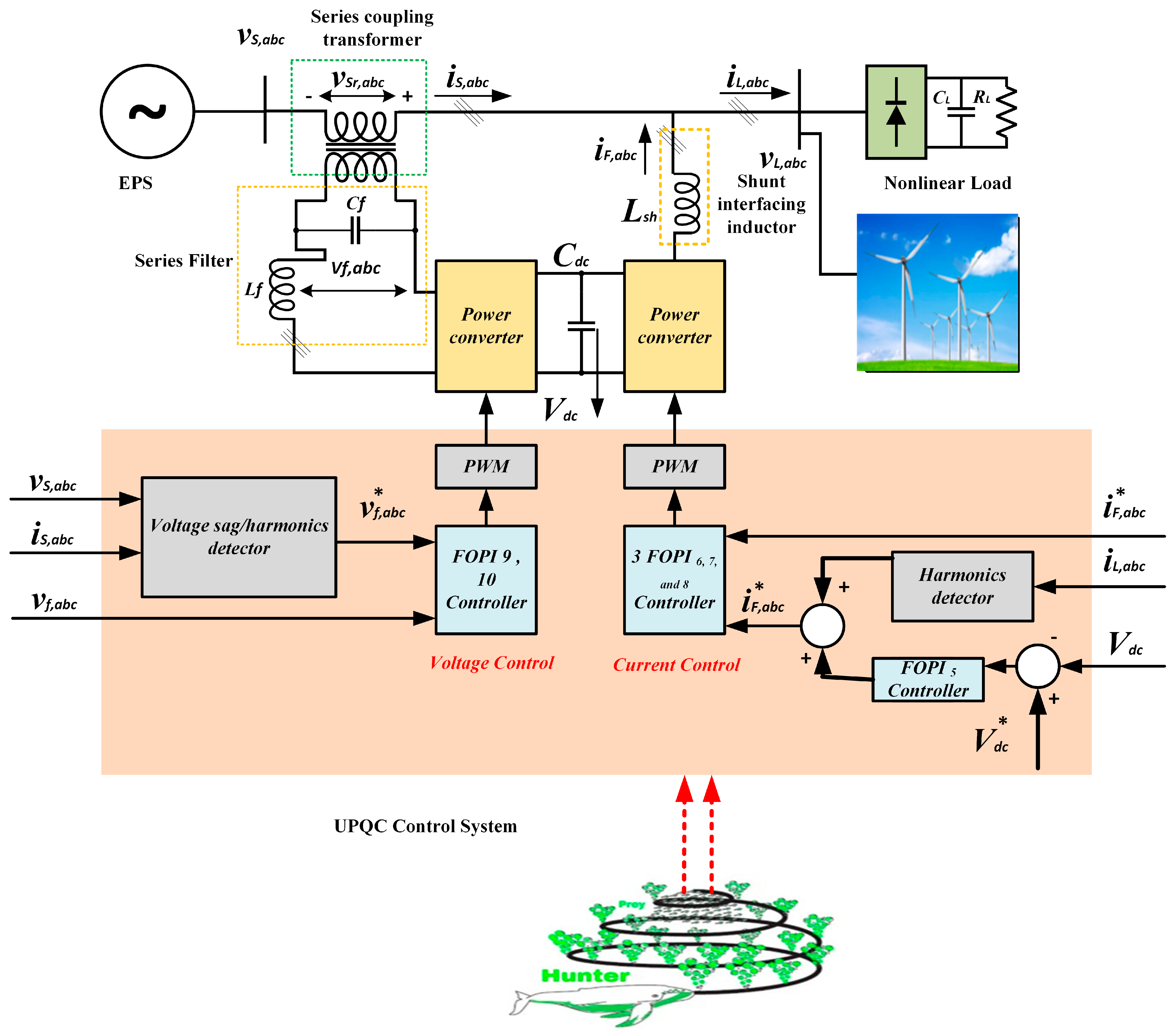
The UPQC is made up of two FACTS devices called DVR and STATCOM, as depicted in Figure 5, so it simultaneously offers their benefits [1]. Nevertheless, UPQC’s approach still limits how effectively PQ may be improved. In this study, a newly created UPQC is used to reduce current and voltage harmonics in an EPS. The mathematical model of the UPQC can be written below. The referenced three-phase currents are estimated as seen in [7,55].
I s a I s b I s c = 2 3 1     0 1 2 3 2 1 2 3 2 V α V β V β V α P Q
The obtained instantaneous load power (P and Q) is used to calculate the instantaneous power angle ( φ ), as shown below:
φ = S i n 1 Q   h a n d e l e d   b y   t h e   D V R P   o f   l o a d
Total power (VA) loading of the UPQC, as a function of φ and the ratio between actual and rated source voltages (k), is represented by:
S U P Q C φ , k = S s h u n t φ , k + S s e r i e s φ , k
The VA loading of the series and shunt can be determined by the following equations:
S s e r i e s φ , k = P s e r i e s φ , k 2 + Q s e r i e s φ , k 2
S s h u n t φ , k = P s h u n t φ , k 2 + Q s h u n t φ , k 2
The Vdc magnitude is:
V d c = 2 2 V l l 3 m
The capacitor rating at the DC bus is:
C d c = 3 k a V p h I S T A T C O M t 0.5 ( V d c 2 V d c 1 2 )
where a is the overloading factor and t is the time required to reach its rated value after an abnormal condition.
The STATCOM interfacing inductor is:
L s h = 3 m V d c 12 a f s h I c r , p p
The DVR interfacing inductor is:
L r = 3 m V d c K s e 12 a f s e I r
where f s h and f s e are the STATCOM and DVR switching frequencies, respectively. The symbol K s e is the transformation ratio of the series transformer.
In this study, an enhanced FOPIC with the help of WOA is presented to enhance the UPQC control performance, as shown in Figure 5. The system detectors can be cancelled with a WOA-based FOPIC, which results in improving its dynamic response. The supply current and load voltage are monitored and adjusted to track the references that correspond to them in the d-q ref. frame via the studied control system. Using a sinusoidal PWM technique, the voltage refs. are used to generate the signals for the two components. Furthermore, a phase-locked loop (PLL) is employed to find the supply voltage’s phase angle to perform coordinated transformations because the suggested technique is built in the d-q ref. frame.

3.3. A Comparison between STATCOM and UPQC Systems

As shown in Table 4, a comparison between STATCOM and UPQC is presented in terms of response time, cost, operation, benefits, drawbacks, and remarks. The points listed here were extrapolated from a number of articles, as seen in Table 4. Both STATCOM and UPQC are regarded as quick, but UPQC is better because it reacts instantly. It is important to note that for the same ratings, UPQC is costlier than STATCOM.

4. Application of Proposed Control Strategy

4.1. WOA Technique

WOA is a meta-heuristic optimization technique informed by nature that imitates the action of humpbacks when hunting. The bubble-net searching technique serves as an inspiration for the technique. Bubble-net dining is the term used to describe humpback whales’ hunting activity. Hunting krill or small fish in schools near the surface is preferred by humpbacks. This hunting has been seen to be accomplished by blowing characteristic bubbles in a circle [60,61,62].
The WOA-based FOPIC’s implementation process can be summarized and its flow chart is depicted in Figure 6, as follows: The agent’s coefficients are KP, Ki, and γ .
1: Create the whale population from scratch X i (i = 1, 2, … n).
2: Determine each searching agent’s fitness level, where X * = the fittest hunting agent.
3: For each hunting agent, the agent brings up-to-date a, A, i, C, and P.
A = 2 a r a
C = 2 r
where both P and r are in the range of [0, 1]. The direct dimension ranges from 2 to 0.
4: If (P < 0.5) and A < 1 .
5: The existing search agent’s situation is updated by the subsequent equation:
X t + 1 = X * t A D
D = C X * ( t ) X ( t )
6: If A 1 , choose a random agent (Xrand), which brings the up-to-date place of the current agent with the following equation:
X t + 1 = X r a n d A D
7: If (P ≥ 0.5), keep posted about the site of the present search by the next equation:
X ' t + 1 = D ' e b l cos 2 π l + X * t
8: If any agent goes beyond the search space and amends it, calculate the fitness of each search, and update X* if there is a better solution t = t + 1 .
9: Choose the new X*.
10: While t = maximal iteration.
11: Yield the optimal gains of Kp, Ki, and γ .

4.2. Application of FOPIC with WOA Technique

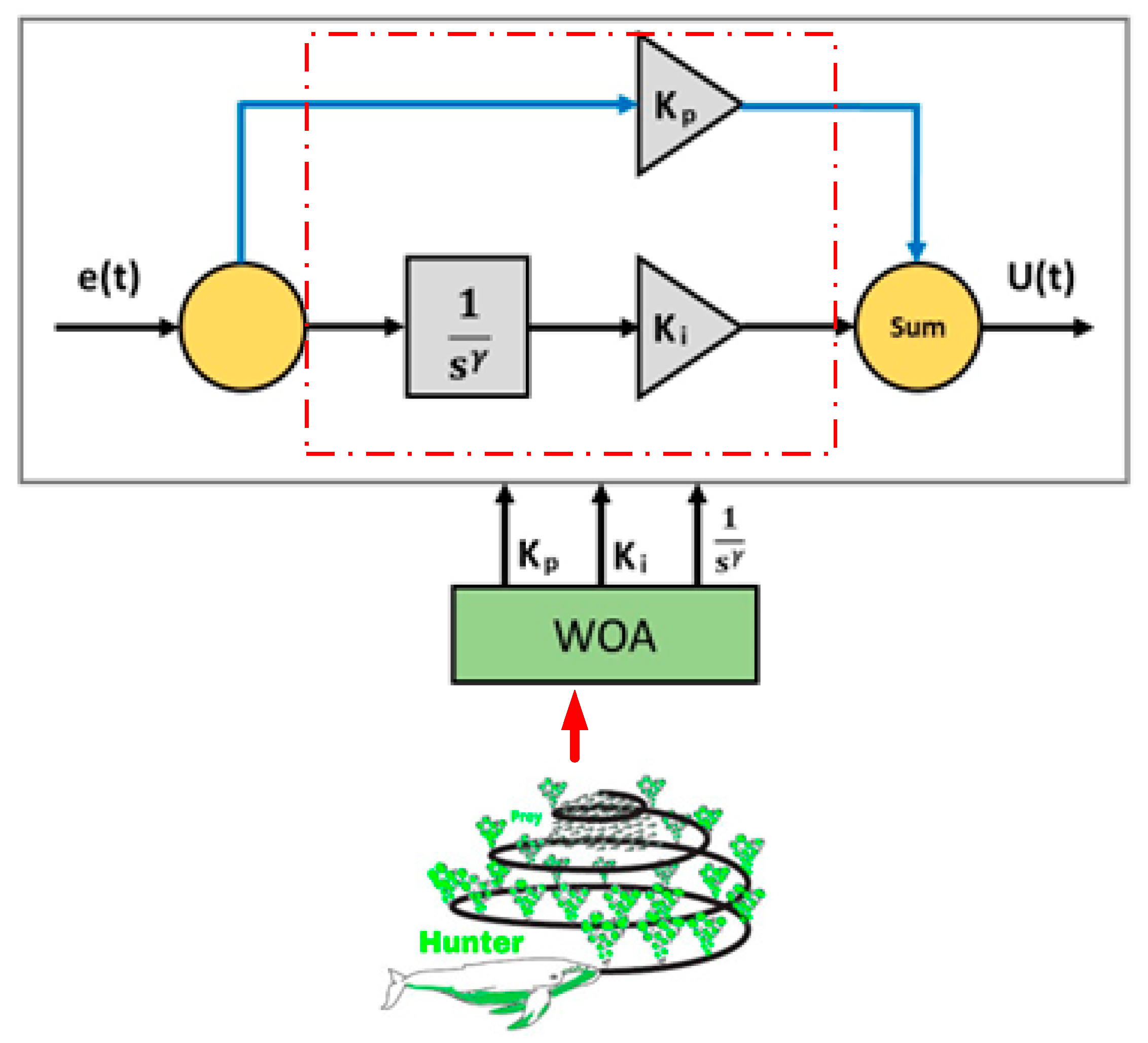
Equation (44) illustrates how the transfer function of the FOPIC works [63,64]. Figure 7 depicts the FOPIC structure. According to proportional gain (Kp), integral gain (Ki), and fractional order ( γ ), the FOPIC values are listed in Table 5 for UPQC and STATCOM. In addition, these values are selected using the WOA approach [65].
U t = K P   e t + K i t γ e t

5. Simulated Results and Discussion

This section provides significant detail about the analysis of the suggested system seen in Figure 2. To conduct a thorough analysis, the proposed EPS’s effective operation is assessed, and the efficacy of the compensation provided by integrating STATCOM and UPQC to enhance the PCC bus voltage portfolio is confirmed; the system is simulated under conditions of a connection of WT, a connection of nonlinear loads, and a transient fault. As indicated in Table 6, three distinct situations based on various configuration methods of the same system are simulated, and matching cases are created. This will make it possible to compare them effectively and aid in determining which scenario offers the best overall performance. In this section, the dynamic and transient responses for each setup scheme are examined independently.

5.1. Application of the STATCOM

The developed STATCOM is linked to the EPS at the PCC bus, as shown in Figure 2. This section outlines how well STATCOM performs in overcoming PQ disruptions. For the purpose of overcoming PQ issues, the STATCOM was designed, developed, and simulated in MATLAB/Simulink. Table 7 lists the system parameters shown in Figure 2.

5.1.1. Scenario 1: Mitigation of Non-Linear Load (S1)

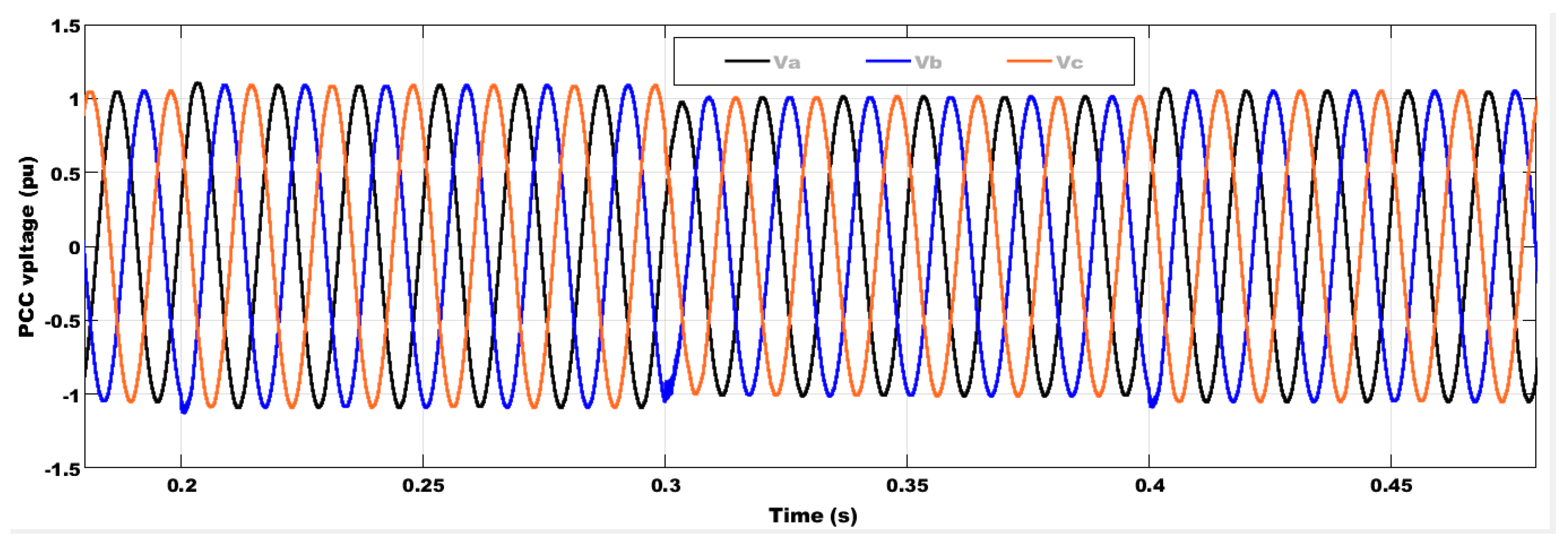
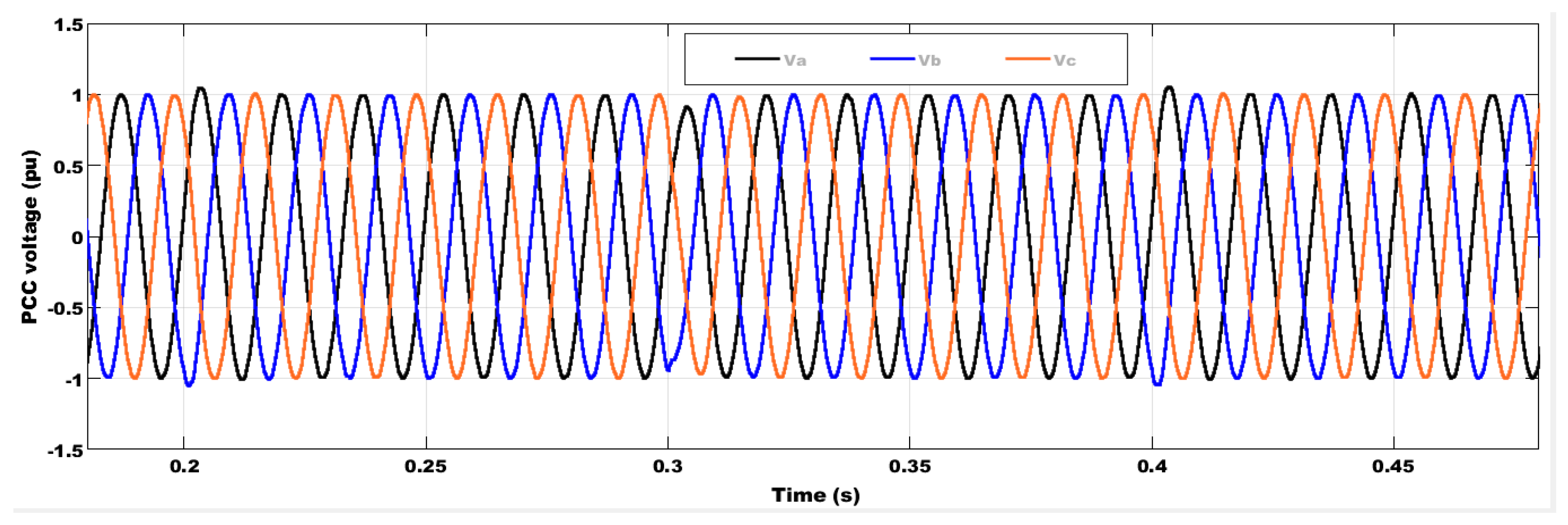
This section investigates how STATCOM successfully handles and mitigates voltage instability and current harmonics at the PCC bus where S1 causes them. Figure 8 and Figure 9 show feeding S1 in the presence and absence of STATCOM to show how STATCOM affects the PCC voltage (PCCV) waveforms, where these waveforms evaluate the performance of STATCOM. The PCCV swings between 1.089 pu and 0.989 pu, as is shown in this instance. In order to maintain the PCCV at close to 1 pu and within the permitted voltage limitations, STATCOM smooths out the PCCV waveforms. Additionally, as shown in Figure 9, STATCOM effectively enhances the voltage quality in a fast reaction duration of roughly 2 ms.
The results clarified in Figure 10 and Figure 11 display the THD without and with STATCOM for the PCC voltage and current when the EPS is tied to S1. Figure 10a,b show that when the STATCOM is interconnected with the system, the THD of the PCC voltage decreases from 4.5% without STATCOM to 2.42% using STATCOM. This is despite the fact that the THD of the PCC bus current is significantly decreased from 20.46% without STATCOM to 5.57% with STATCOM, as depicted in Figure 11a,b. The percentage reduction in THD is about 46.22% and 72.78% for the PCC bus voltage and current, respectively, which indicates a significant enhancement in these waveforms.

5.1.2. Scenario 2: Mitigation of 42% Penetration of Wind Energy (S2)

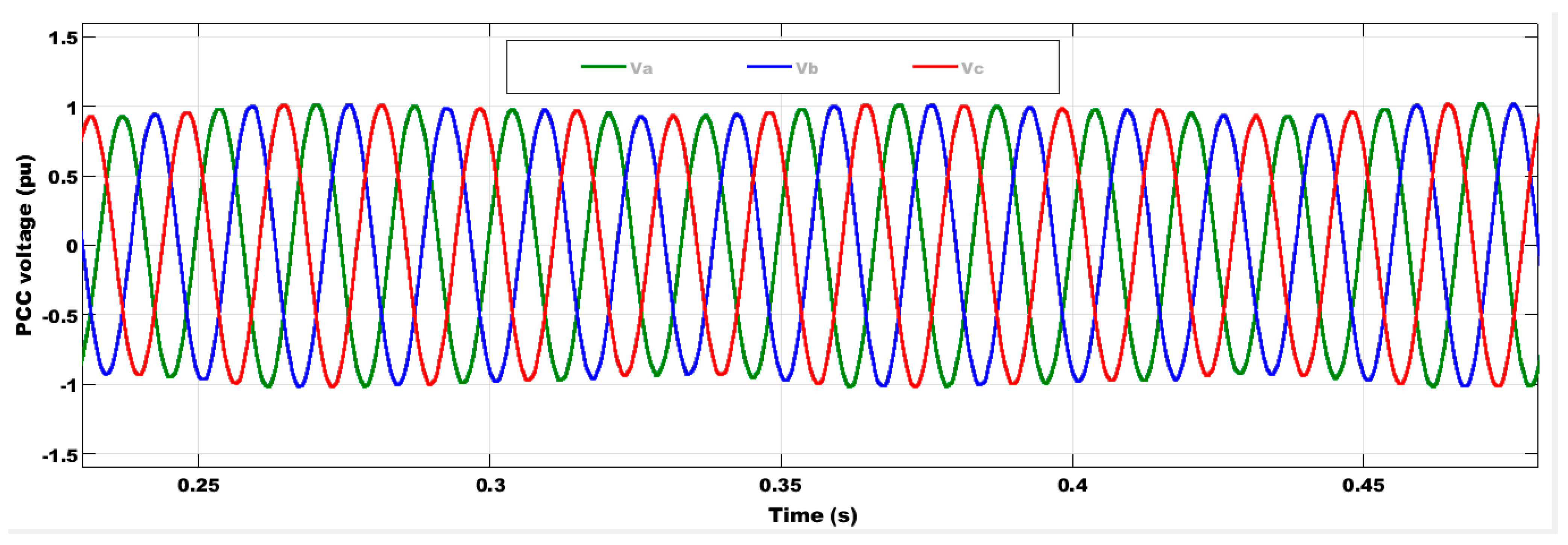
The EPS is linked to S2 in this instance, which causes harmonics in the voltage and current at the PCC bus. It is obvious from this that the PCCV varies between 1.019 pu and 0.939 pu as depicted in Figure 12. The effect of STATCOM on reducing voltage fluctuations is shown in Figure 13. This improvement in the PCCV waveforms is because of the STATCOM’s ability to regulate the PCCV around 1 pu. The obtained simulated results ensure the capability of STATCOM to overcome all of these unfavorable disturbances, which enhances the power system stability and reliability.
The results illustrated in Figure 14 and Figure 15 show the THD without and with STATCOM for the PCC bus voltage and current when the EPS is tied to S2. Figure 14a,b shows that when the STATCOM is connected to the system, the THD of the PCC bus voltage is reduced from 16.25% without STATCOM to 1.62% with STATCOM, while the THD of the feeder bus current is significantly reduced from 4.18% without STATCOM to 5.47% with STATCOM, as depicted in Figure 15a,b. The percentage reduction in THD is about 61.24% and 66.34% for the PCC bus voltage and current, respectively, which is a significant improvement in these waveforms. It can be noticed that the performance of STATCOM under S1 is similar to that under S2.

5.1.3. Scenario 3: Mitigation of Three-Phase to Ground Fault (S3)

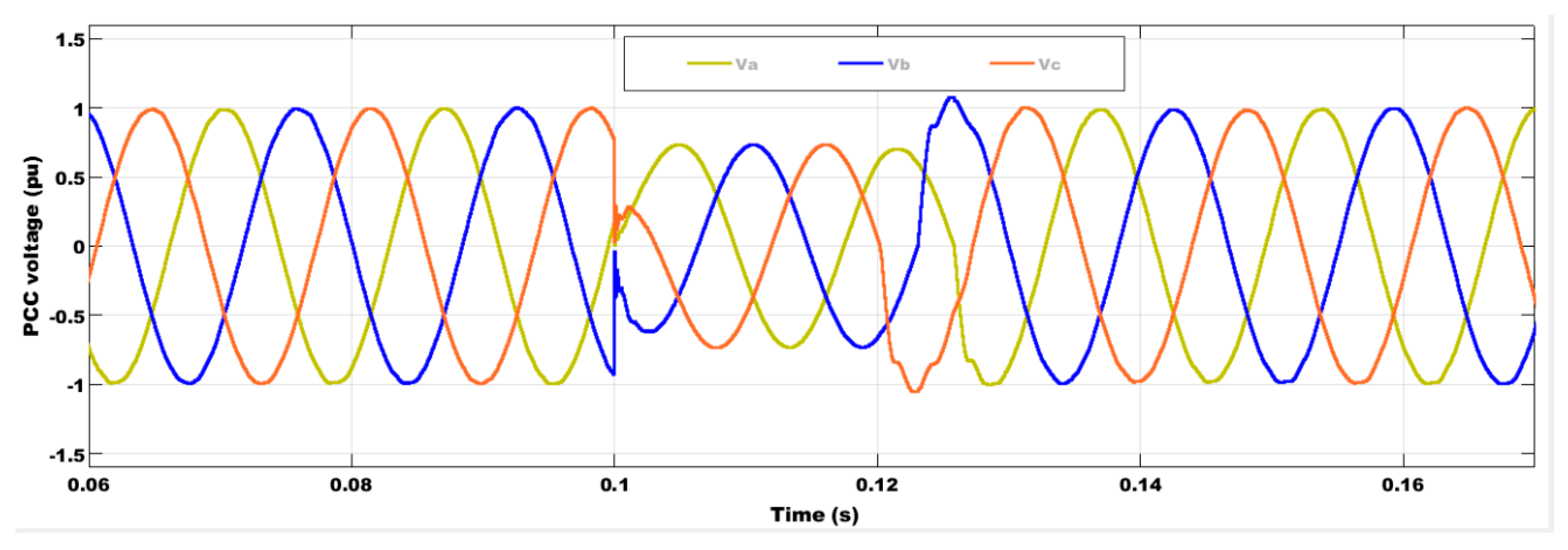
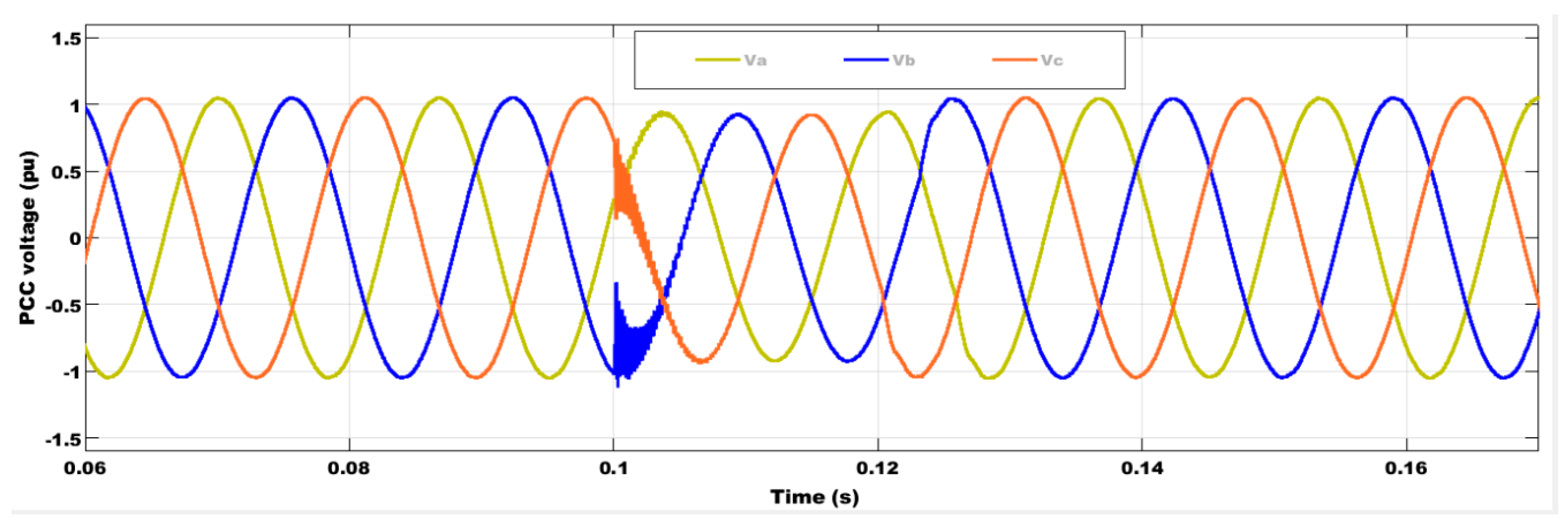
This study presents S3 during 0.1 s–0.12 s, which is well thought-out and one of the most hazardous kinds of fault. It is important to note that STATCOM can manage system faults, which are frequent problems that can lead to system instability and are examined in this study. The PCCV decreased to 0.74 pu of its base value without STATCOM during the faults period, and EPS instability was observed, as shown in Figure 16. The PCCV bus limit increased to 0.95 pu thanks to STATCOM, as shown in Figure 17, which demonstrates the utility of STATCOM.

5.2. Application of the UPQC

The application of UPQC is shown in Figure 2, where it is used to connect the modern SG system with the EPS. The UPQC is used to aid in solving PQ issues and improve the power system’s reliability. The addressed UPQC rating is 700 kVAR and all the system parameters were mentioned earlier in Table 4.

5.2.1. Scenario 1: Non-Linear Load (S1) Mitigation

The EPS is coupled with S1 in this instance. It is quite probable that the PCC bus will experience voltage distortion, and voltage and current harmonics. By integrating S1 between 0.1 and 0.22 s, the UPQC eliminates voltage distortion. As demonstrated in Figure 18, the voltage approaches 1 pu (pure sine wave), and the voltage is maintained within acceptable bounds.
When the UPQC with its control system is connected, the THD of the PCC voltage, which was 4.5% without it, is reduced to 1.5%, as seen in Figure 19. Similar to this, the PCC current’s THD in the basic configuration is 20.46%, but with UPQC, it is just 2.3%, as depicted in Figure 20.

5.2.2. Scenario 2: 42% Penetration of Wind Energy (S2) Mitigation

High penetration of the SCIG-based WE scenario is considered to highlight the impact of the UPQC in reducing the THD of the PCC bus voltage for improving PQ. The waveform of the PCC bus voltage when UPQC is illustrated in Figure 21. In C3 under S2, the THD of the PCC voltage was 4.5% and in C1 under S2, the THD decreased to 0.16%, as seen in Figure 22.

5.2.3. Scenario 3: Three-Phase to Ground Fault (S3) Mitigation

Amongst the most hazardous fault types, S3, which happens in this situation between 0.1 and 0.12 s, causes PCC voltage instability. The PCC voltage dip (0.74 pu) caused by this failure is depicted in Figure 16. The UPQC, on the other hand, defeats S3 and restricts voltage to almost 1 pu (pure sine wave), maintaining the EPS stability, as shown in Figure 23. It may therefore effectively handle any fault condition. It can be mentioned that the suggested configuration can achieve FRT capability.
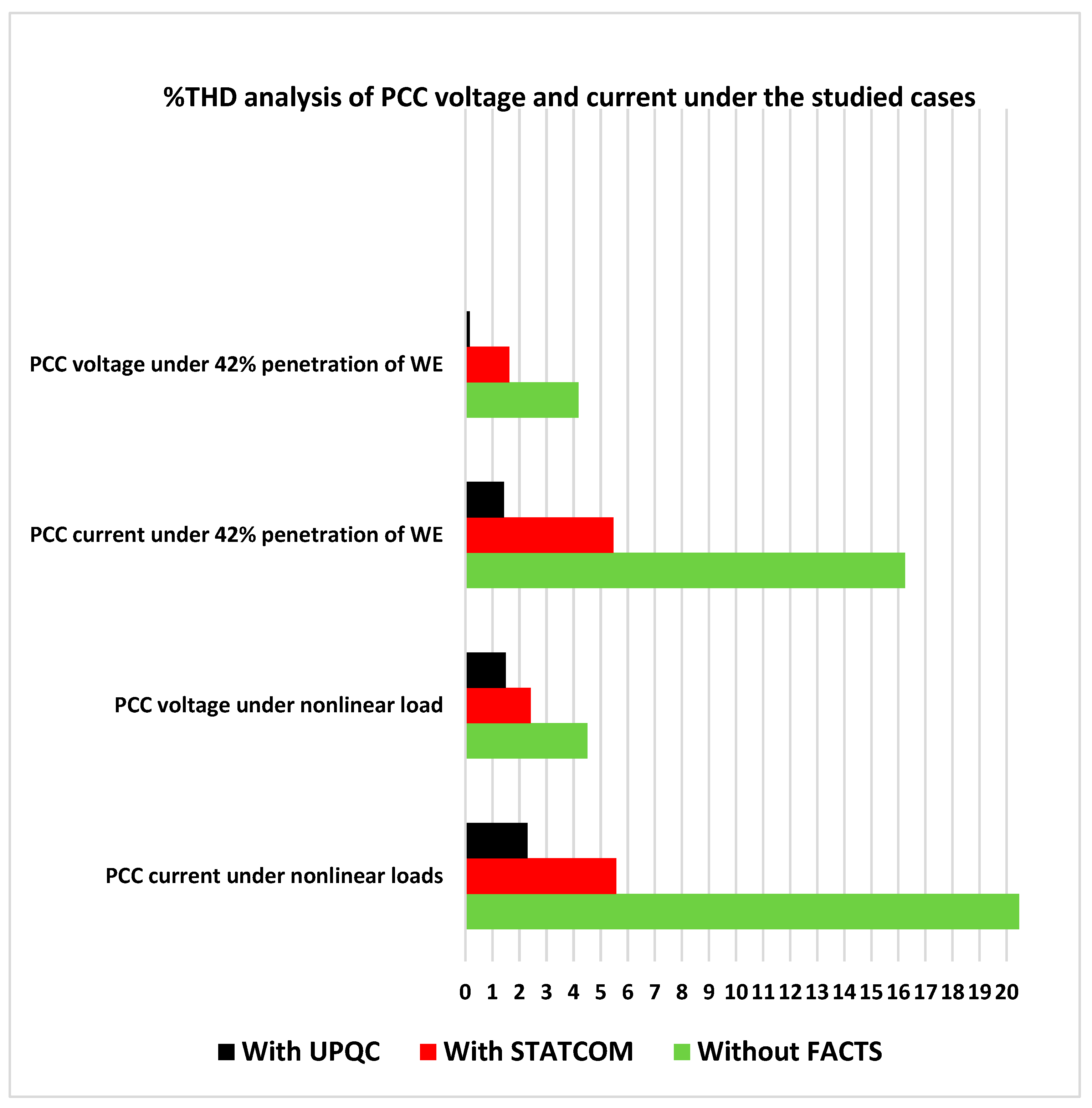
Table 8 illustrates the THD values of the voltage and current at the PCC bus for the three studied configurations in S1 and S2, for which the table demonstrates how impressively well the UPQC solution outperformed the STATCOM solution in terms of handling harmonics. As a result, both preserved the PQ and reliability of the system under consideration. The bar chart in Figure 24 is used to display the performance comparison of the studied configurations in terms of percentage figures for %THD of PCC voltage and current to highlight the superiority of UPQC. In particular, it is useful for showing the relationship between C1, C2, and C3 and the %THD under S1 and S2. In addition, PCC voltage values during the different studied operating conditions are listed in Table 9. Furthermore, to highlight the key performance differences between the UPQC reported in [66] and the proposed UPQC, Table 10 is shown.

6. Conclusions and Future Research Directions

This study analyzed the effects of STATCOM, and UPQC operated with WOA-based FOPIC, on EPS stability and PQ improvement using three different configurations (C1, C2, and C3). Three different operating scenarios (S1, S2, and S3) were used to study C1, C2, and C3. Both STATCOM and UPQC inject current to cancel out Q and harmonic parts of the load, which enhances the overall system performance. Modeling and comprehensive study of the investigated FACTS devices were presented to show their benefits and capabilities for enhancing PQ issues.
The findings revealed that C1 has better accuracy than both C2 and C3 in reducing THD percentage and damping the voltage oscillations in the case of all simulation scenarios. Furthermore, in light of the comparative simulation results of C1, C2, and C3 in all studied simulated scenarios, it can be concluded that C1 outperforms the other approaches and significantly boosts the system’s reliability.
S1, S2, and S3 showed that the STATCOM was efficient in overcoming harmonics issues by decreasing THD to an acceptable level according to the IEEE standards, although UPQC is remarkable at resolving these problems. The percentage reduction in THD presented by C1 is interesting compared to that of C2 and C3. C2 successfully avoided voltage instability by a percentage of 98%, whereas C1 nearly completely overcame the voltage distortion. Furthermore, C2 controlled the PCC bus voltage during the fault period by 95%, whereas the control of C1 was close to 100%. Finally, it can be said that the optimal solution is to use C2 for PQ problems caused by voltage fluctuations and dips, and C1 for highly sensitive loads. The future research directions for this work are presented in the following points:
  • Comparing the wind generators under different penetration levels to show the best type for ensuring the studied system is more reliable with low THD.
  • Applying new optimization methods to determine the optimal size of the integrated FACTS tools.
  • Installing PV instead of a wind generator to show the best option for ensuring the studied system is more stable with low THD.
  • Installing storage systems instead of FACTS in the studied system to show the best solution.
  • Applying the developed FACTS tools to microgrids.

Author Contributions

Conceptualization, M.M.M. and B.S.A.; methodology, Y.M.E.; software, S.A.E.M.A.; validation, N.A. and A.I.O.; formal analysis, S.A.M.; investigation, M.M.M.; resources, N.A.; data curation, A.I.O.; writing—original draft preparation, M.M.M.; writing—review and editing, F.A. and S.A.; supervision, S.A.; project administration, F.A.; funding acquisition, F.A. and S.A. All authors have read and agreed to the published version of the manuscript.

Funding

This research received no external funding.

Data Availability Statement

Data are available on request from the authors.

Acknowledgments

This work was supported by the Researchers Supporting Project number (RSPD2023R646), King Saud University, Riyadh, Saudi Arabia.

Conflicts of Interest

The authors declare no conflict of interest.

References

  1. Aljendy, R.; Nasyrov, R.R.; Abdelaziz, A.Y.; Diab, A.A.Z. Enhancement of Power Quality with Hybrid Distributed Generation and FACTS Device. IETE J. Res. 2019, 68, 2259–2270. [Google Scholar] [CrossRef]
  2. Mohamed, S.A.; Tolba, M.A.; Eisa, A.A.; El-Rifaie, A.M. Comprehensive Modeling and Control of Grid-Connected Hybrid Energy Sources Using MPPT Controller. Energies 2021, 14, 5142. [Google Scholar] [CrossRef]
  3. Reddy, C.R.; Goud, B.S.; Aymen, F.; Rao, G.S.; Bortoni, E.C. Power Quality Improvement in HRES Grid Connected System with FOPID Based Atom Search Optimization Technique. Energies 2021, 14, 5812. [Google Scholar] [CrossRef]
  4. Elmetwaly, A.H.; Younis, R.A.; Abdelsalam, A.A.; Omar, A.I.; Mahmoud, M.M.; Alsaif, F.; El-Shahat, A.; Saad, M.A. Modeling, Simulation, and Experimental Validation of a Novel MPPT for Hybrid Renewable Sources Integrated with UPQC: An Application of Jellyfish Search Optimizer. Sustainability 2023, 15, 5209. [Google Scholar] [CrossRef]
  5. Boudjemai, H.; Ardjoun, S.A.E.M.; Chafouk, H.; Denai, M.; Elbarbary, Z.M.S.; Omar, A.I.; Mahmoud, M.M. Application of a Novel Synergetic Control for Optimal Power Extraction of a Small-Scale Wind Generation System with Variable Loads and Wind Speeds. Symmetry 2023, 15, 369. [Google Scholar] [CrossRef]
  6. Singh, B.; Chandra, A.; Al-Haddad, K. Power Quality Problems and Mitigation Techniques; John Wiley and Sons: Hoboken, NJ, USA, 2015; Volume 9781118922. [Google Scholar] [CrossRef]
  7. Sankar, A.M.; Raju, T.D.; Kumar, M.V. DSP-based identification, classification and mitigation of power quality disturbances using UPQC. Int. J. Ambient. Energy 2020, 41, 41–49. [Google Scholar] [CrossRef]
  8. Li, B.-S.; Ge, Y.-M. Improving Power Quality by Smart Load. Energy Procedia 2012, 17, 813–817. [Google Scholar] [CrossRef] [Green Version]
  9. Mahmoud, M.M. Improved current control loops in wind side converter with the support of wild horse optimizer for enhancing the dynamic performance of PMSG-based wind generation system. Int. J. Model. Simul. 2022, 1–15. [Google Scholar] [CrossRef]
  10. Mahmoud, M.M.; Ratib, M.K.; Raglend, I.J.; Swaminathan, J.; Aly, M.M.; Abdel-Rahim, A.-M.M. Application of Grey Wolf Optimization for PMSG-Based WECS under Different Operating Conditions: Performance Assessment. In Proceedings of the 2021 Innovations in Power and Advanced Computing Technologies (i-PACT), Kuala Lumpur, Malaysia, 27–29 November 2021; pp. 1–7. [Google Scholar] [CrossRef]
  11. Monedero, I.; Leon, C.; García, A.; Elena, J.; Montañó, J.; Ropero, J. A real-time system for the generation and detection of electrical disturbances. In Series on Energy and Power Systems. In Proceedings of the IEEE PES Power Systems Conference and Exposition, New York, NY, USA, 10–13 October 2004; pp. 180–185. [Google Scholar] [CrossRef]
  12. Mahmoud, M.M.; Ratib, M.K.; Aly, M.M.; Abdel-Rahim, A.-M.M. Wind-driven permanent magnet synchronous generators connected to a power grid: Existing perspective and future aspects. Wind. Eng. 2021, 46, 189–199. [Google Scholar] [CrossRef]
  13. Mahmoud, M.M.; Atia, B.S.; Abdelaziz, A.Y.; Aldin, N.A.N. Dynamic Performance Assessment of PMSG and DFIG-Based WECS with the Support of Manta Ray Foraging Optimizer Considering MPPT, Pitch Control, and FRT Capability Issues. Processe 2022, 12, 2723. [Google Scholar]
  14. Mahmoud, M.M.; Aly, M.M.; Abdel-Rahim, A.-M.M. Enhancing the dynamic performance of a wind-driven PMSG implementing different optimization techniques. SN Appl. Sci. 2020, 2, 684. [Google Scholar] [CrossRef] [Green Version]
  15. Mahmoud, M.M.; Salama, H.S.; Aly, M.M.; Abdel-Rahim, A.-M.M. Design and implementation of FLC system for fault ride-through capability enhancement in PMSG-wind systems. Wind. Eng. 2021, 45, 1361–1373. [Google Scholar] [CrossRef]
  16. Devadason, J.; Moses, P.S.; Masoum, M.A.S. Stability Domain Analysis and Enhancement of Squirrel Cage Induction Generator Wind Turbines in Weak Grids. Energies 2021, 14, 4786. [Google Scholar] [CrossRef]
  17. Jamil, E.; Hameed, S.; Jamil, B. Qurratulain Power quality improvement of distribution system with photovoltaic and permanent magnet synchronous generator based renewable energy farm using static synchronous compensator. Sustain. Energy Technol. Assessments 2019, 35, 98–116. [Google Scholar] [CrossRef]
  18. Meral, M.E.; Çelik, D. DSOGI-PLL Based Power Control Method to Mitigate Control Errors Under Disturbances of Grid Connected Hybrid Renewable Power Systems. Adv. Electr. Electron. Eng. 2018, 16, 81–91. [Google Scholar] [CrossRef]
  19. Pang, M.; Shi, Y.; Wang, W.; Pang, S. Optimal sizing and control of hybrid energy storage system for wind power using hybrid Parallel PSO-GA algorithm. Energy Explor. Exploit. 2019, 37, 558–578. [Google Scholar] [CrossRef] [Green Version]
  20. Zarkani, M.K.; Tukkee, A.S.; Alali, M.J. Optimal placement of facts devices to reduce power system losses using evolutionary algorithm. Indones. J. Electr. Eng. Comput. Sci. 2021, 21, 1271–1278. [Google Scholar] [CrossRef]
  21. Mahmoud, M.M.; Atia, B.S.; Esmail, Y.M.; Bajaj, M.; Wapet, D.E.M.; Ratib, M.K.; Hossain, B.; AboRas, K.M.; Abdel-Rahim, A.-M.M. Evaluation and Comparison of Different Methods for Improving Fault Ride-Through Capability in Grid-Tied Permanent Magnet Synchronous Wind Generators. Int. Trans. Electr. Energy Syst. 2023, 2023, 7717070. [Google Scholar] [CrossRef]
  22. Mahmoud, M.M.; Esmail, Y.M.; Atia, B.S.; Kamel, O.M.; AboRas, K.M.; Bajaj, M.; Bukhari, S.S.H.; Wapet, D.E.M. Voltage Quality Enhancement of Low-Voltage Smart Distribution System Using Robust and Optimized DVR Controllers: Application of the Harris Hawks Algorithm. Int. Trans. Electr. Energy Syst. 2022, 2022, 4242996. [Google Scholar] [CrossRef]
  23. Mohod, S.W.; Aware, M.V. A STATCOM-Control Scheme for Grid Connected Wind Energy System for Power Quality Improvement. IEEE Syst. J. 2010, 4, 346–352. [Google Scholar] [CrossRef]
  24. Qi, J.; Zhao, W.; Bian, X. Comparative Study of SVC and STATCOM Reactive Power Compensation for Prosumer Microgrids With DFIG-Based Wind Farm Integration. IEEE Access 2020, 8, 209878–209885. [Google Scholar] [CrossRef]
  25. George, S.K.; Chacko, F.M. Comparison of different control strategies of STATCOM for power quality improvement of grid connected wind energy system. In Proceedings of the 2013 International Mutli Conference on Automation, Computing, Communication, Control and Compressed Sensing (iMac4s), Kottayam, India, 22–23 March 2013; pp. 650–655. [Google Scholar] [CrossRef]
  26. Mahmoud, M.M.; Salama, H.S.; Bajaj, M.; Aly, M.M.; Vokony, I.; Bukhari, S.S.H.; Wapet, D.E.M.; Abdel-Rahim, A.-M.M. Integration of Wind Systems with SVC and STATCOM during Various Events to Achieve FRT Capability and Voltage Stability: Towards the Reliability of Modern Power Systems. Int. J. Energy Res. 2023, 2023, 8738460. [Google Scholar] [CrossRef]
  27. Fayek, A.; Salimullah, S.M.; Hossain, S.; Hossain, R.; Shakib, S.H.; Anik, A.I.; Khan, M.H. STATCOM and PID Controller Based Stability Enhancement of a Grid Connected Wind Farm. In Proceedings of the 2019 International Conference on Energy and Power Engineering (ICEPE), Dhaka, Bangladesh, 14–16 March 2019; pp. 1–4. [Google Scholar] [CrossRef]
  28. Kamel, O.M.; Diab, A.A.Z.; Mahmoud, M.M.; Al-Sumaiti, A.S.; Sultan, H.M. Performance Enhancement of an Islanded Microgrid with the Support of Electrical Vehicle and STATCOM Systems. Energies 2023, 16, 1577. [Google Scholar] [CrossRef]
  29. Kulkarni, H.R.; Virulkar, V.B. Mitigation of flicker in a distribution-connected wind farm with STATCOM. In Proceedings of the 2017 International Conference on Energy, Communication, Data Analytics and Soft Computing, ICECDS, Chennai, India, 1–2 August 2018; pp. 2208–2212. [Google Scholar] [CrossRef]
  30. Sreenivasarao, D.; Agarwal, P.; Das, B. Performance enhancement of a reduced rating hybrid D-STATCOM for three-phase, four-wire system. Electr. Power Syst. Res. 2013, 97, 158–171. [Google Scholar] [CrossRef]
  31. Rezaeipour, R.; Kiani, B. Review of novel control techniques for STATCOM and its effects on a wind farm. In Proceedings of the 2009 International Conference on Sustainable Power Generation and Supply, Nanjing, China, 6–7 April 2009; pp. 1–5. [Google Scholar] [CrossRef]
  32. Madhusudan, R.; Rao, G.R. Modeling and simulation of a distribution STATCOM (D-STATCOM) for power quality problems-voltage sag and swell based on Sinusoidal Pulse Width Modulation (SPWM). In Proceedings of the IEEE-International Conference on Advances in Engineering, Science and Management, ICAESM-2012, Tamil Nadu, India, 30–31 March 2012; pp. 436–441. [Google Scholar]
  33. Paramanik, S.; Sarker, K.; Chatterjee, D.; Goswami, S. Smart Grid Power Quality Improvement Using Modified UPQC. In Proceedings of the 2019 Devices for Integrated Circuit (DevIC), Kalyani, India, 23–24 March 2019; pp. 356–360. [Google Scholar] [CrossRef]
  34. Khadkikar, V.; Chandra, A. A Novel Structure for Three-Phase Four-Wire Distribution System Utilizing Unified Power Quality Conditioner (UPQC). IEEE Trans. Ind. Appl. 2009, 45, 1897–1902. [Google Scholar] [CrossRef]
  35. Diab, M.; El-Habrouk, M.; Abdelhamid, T.H.; Deghedie, S. Survey of Active Power Filters Configurations. In Proceedings of the 2018 IEEE International Conference on System, Computation, Automation and Networking (ICSCA), Pondicherry, India, 6–7 July 2018; pp. 1–14. [Google Scholar] [CrossRef]
  36. Ye, J.; Gooi, H.B.; Wu, F. Optimal Design and Control Implementation of UPQC Based on Variable Phase Angle Control Method. IEEE Trans. Ind. Inform. 2018, 14, 3109–3123. [Google Scholar] [CrossRef]
  37. Gade, S.; Agrawal, R.; Munje, R. Recent Trends in Power Quality Improvement: Review of the Unified Power Quality Conditioner. ECTI Trans. Electr. Eng. Electron. Commun. 2021, 19, 268–288. [Google Scholar] [CrossRef]
  38. Khadkikar, V. Enhancing Electric Power Quality Using UPQC: A Comprehensive Overview. IEEE Trans. Power Electron. 2012, 27, 2284–2297. [Google Scholar] [CrossRef]
  39. Osaloni, O.O.; Saha, A.K. Voltage Dip/Swell Mitigation and Imaginary Power Compensation in Low Voltage Distribution Utilizing Improved Unified Power Quality Conditioner (I-UPQC). Int. J. Eng. Res. Afr. 2020, 49, 84–103. [Google Scholar] [CrossRef]
  40. Mahmoud, M.M.; Hemeida, A.M.; Senjy, T.; Ewais, A.M. Fault Ride-Through Capability Enhancement for Grid-Connected Permanent Magnet Synchronous Generator Driven by Wind Turbines. In Proceedings of the 2019 IEEE Conference on Power Electronics and Renewable Energy (CPERE), Aswan, Egypt, 23–25 October 2019; pp. 567–572. [Google Scholar] [CrossRef]
  41. Singh, K.; Mishra, S.; Kumar, M.N. A Review on Power Management and Power Quality for Islanded PV Microgrid in Smart Village. Indian J. Sci. Technol. 2017, 10, 1–4. [Google Scholar] [CrossRef]
  42. Ceaki, O.; Seritan, G.; Vatu, R.; Mancasi, M. Analysis of power quality improvement in smart grids. In Proceedings of the 2017 10th International Symposium on Advanced Topics in Electrical Engineering (ATEE), Bucharest, Romania, 23–25 March 2017; pp. 797–801. [Google Scholar] [CrossRef]
  43. Johnson, D.O. Issues of Power Quality in Electrical Systems. Int. J. Energy Power Eng. 2016, 5, 148. [Google Scholar] [CrossRef]
  44. Bagdadee, A.H.; Zhang, L. Power Quality improvement provide Digital Economy by the Smart Grid. IOP Conf. Series Mater. Sci. Eng. 2019, 561, 012097. [Google Scholar] [CrossRef] [Green Version]
  45. Jolhe, S.P.; Karalkar, M.D.; Dhomane, G.A. Smart grid and power quality (PQ) issues. In Proceedings of the 2016 Online International Conference on Green Engineering and Technologies (IC-GET), Coimbatore, India, 19 November 2016; pp. 1–3. [Google Scholar] [CrossRef]
  46. De-La-Rosa, J.-J.G.; Pérez-Donsión, M. Special Issue “Analysis for Power Quality Monitoring”. Energies 2020, 13, 514. [Google Scholar] [CrossRef] [Green Version]
  47. Sunil, T.P.; Loganathan, N. Power quality improvement of a grid-connected wind energy conversion system with har-monics reduction using FACTS device. In Proceedings of the IEEE-International Conference on Advances in Engineering, Science and Management, ICAESM-2012, Tamil Nadu, India, 30–31 March 2012; pp. 415–420. [Google Scholar]
  48. Devabalaji, K.; Ravi, K. Power quality improvement in wind farm connected to grid using STATCOM. In Proceedings of the 2014 International Conference on Advances in Electrical Engineering (ICAEE), Vellore, India, 9–11 January 2014; pp. 1–5. [Google Scholar] [CrossRef]
  49. Amita, A.; Sinha, A.K. Power Quality Comparison of Grid Connected wind Energy System with STATCOM and UPQC. In Proceedings of the 2018 International Conference on Intelligent Circuits and Systems (ICICS), Phagwara, India, 19–20 April 2018; pp. 355–360. [Google Scholar] [CrossRef]
  50. Mohammed, A.B.; Ariff, M.A.M.; Ramli, S.N. Power quality improvement using dynamic voltage restorer in electrical distribution system: An overview. Indones. J. Electr. Eng. Comput. Sci. 2019, 17, 86–93. [Google Scholar] [CrossRef]
  51. Jiao, W.; Chen, J.; Wu, Q.; Li, C.; Zhou, B.; Huang, S. Distributed Coordinated Voltage Control for Distribution Networks with DG and OLTC Based on MPC and Gradient Projection. IEEE Trans. Power Syst. 2022, 37, 680–690. [Google Scholar] [CrossRef]
  52. Jamil, E.; Qurratulain; Hameed, S. STATCOM-Based Voltage Regulation in Grid Integrated Wind Farm under Variable Loading Conditions. In Proceedings of the 2017 14th IEEE India Council International Conference (INDICON), Roorkee, India, 15–17 December 2018; pp. 1–6. [Google Scholar] [CrossRef]
  53. Varma, R.K.; Akbari, M. Simultaneous Fast Frequency Control and Power Oscillation Damping by Utilizing PV Solar System as PV-STATCOM. IEEE Trans. Sustain. Energy 2020, 11, 415–425. [Google Scholar] [CrossRef]
  54. Khadem, S.K.; Basu, M.; Conlon, M. Power Quality in Grid connected Renewable Energy Systems: Role of Custom Power Devices. Renew. Energy Power Qual. J. 2010, 1, 878–881. [Google Scholar] [CrossRef] [Green Version]
  55. Lakshmi, S.; Ganguly, S. A comparative study among UPQC models with and without real power injection to improve energy efficiency of radial distribution networks. Energy Syst. 2020, 11, 113–138. [Google Scholar] [CrossRef]
  56. Kesler, M.; Ozdemir, E. Synchronous-Reference-Frame-Based Control Method for UPQC Under Unbalanced and Distorted Load Conditions. IEEE Trans. Ind. Electron. 2011, 58, 3967–3975. [Google Scholar] [CrossRef]
  57. Trinh, Q.-N.; Lee, H.-H. Novel Control Strategy for a UPQC under Distorted Source and Nonlinear Load Conditions. J. Power Electron. 2013, 13, 161–169. [Google Scholar] [CrossRef] [Green Version]
  58. Lara, O.A.; Jenkins, N.; Ekanayake, J. Wind Energy Generation Systems: Modelling and Control; John Wiley & Sons: Hoboken, NJ, USA, 2009; Volume 54. [Google Scholar]
  59. Abdou, A.F.; Pota, H.R.; Abu-Siada, A.; Alharbi, Y.M. Application of STATCOM-HTS to improve DFIG performance and FRT during IGBT short circuit. In Proceedings of the 2014 Australasian Universities Power Engineering Conference (AUPEC), Perth, WA, Australia, 28 September–1 October 2014; pp. 1–5. [Google Scholar] [CrossRef]
  60. Mahmoud, M.M.; Ratib, M.K.; Aly, M.M.; Abdel–Rahim, A.-M.M. Application of Whale Optimization Technique for Evaluating the Performance of Wind-Driven PMSG Under Harsh Operating Events. Process. Integr. Optim. Sustain. 2022, 6, 447–470. [Google Scholar] [CrossRef]
  61. Baidar, L.; Rahmoun, A.; Lorenz, P.; Mihoubi, M. Whale Optimization Approach for Optimization Problem in Distributed Wireless Sensor Network. In Proceedings of the 9th International Conference on Information Systems and Technologies, Cairo, Egypt, 24–26 March 2019; p. 19. [Google Scholar] [CrossRef]
  62. Mirjalili, S.; Lewis, A. The Whale Optimization Algorithm. Adv. Eng. Softw. 2016, 95, 51–67. [Google Scholar] [CrossRef]
  63. Goud, B.S.; Reddy, C.R.; Rakesh, T.; Rajesh, N.; Reddy, B.N.; Aymen, F. Grid Integration of Renewable Energy Sources using GA Technique for Improving Power Quality. Int. J. Renew. Energy Res. 2021, 11, 1390–1402. [Google Scholar] [CrossRef]
  64. Kahla, S.; Bechouat, M.; Amieur, T.; Sedraoui, M.; Babes, B.; Hamouda, N. Maximum power extraction framework using robust fractional-order feedback linearization control and GM-CPSO for PMSG-based WECS. Wind. Eng. 2021, 45, 1040–1054. [Google Scholar] [CrossRef]
  65. George, T.; Ganesan, V. Design of fractional order PID controller for higher order time delay system using NOARBFN technique. Energy Syst. 2021, 1–32. [Google Scholar] [CrossRef]
  66. Kenjrawy, H.; Makdisie, C.; Houssamo, I.; Mohammed, N. New Modulation Technique in Smart Grid Interfaced Multilevel UPQC-PV Controlled via Fuzzy Logic Controller. Electronics 2022, 11, 919. [Google Scholar] [CrossRef]
Figure 1. Percentage of PQ disruptions.
Axioms 12 00420 g001
Figure 2. The addressed configuration.
Axioms 12 00420 g002
Figure 3. Dynamic modeling of WT system.
Axioms 12 00420 g003
Figure 4. Configuration of WOA-based FOPI of STATCOM connected to the grid.
Axioms 12 00420 g004
Figure 5. UPQC structure with its proposed control system.
Axioms 12 00420 g005
Figure 6. WOA technique flowchart.
Axioms 12 00420 g006
Figure 7. WOA-based FOPIC.
Axioms 12 00420 g007
Figure 8. The PCCV waveform without STATCOM.
Axioms 12 00420 g008
Figure 9. The PCCV waveform in the presence of STATCOM.
Axioms 12 00420 g009
Figure 10. THD of the PCC bus voltage (a) without STATCOM (b) with STATCOM.
Axioms 12 00420 g010
Figure 11. THD of the PCC bus current (a) without STATCOM (b) with STATCOM.
Axioms 12 00420 g011
Figure 12. The PCCV waveform without STATCOM.
Axioms 12 00420 g012
Figure 13. The PCCV waveform in the presence of STATCOM.
Axioms 12 00420 g013
Figure 14. THD of the PCC bus voltage (a) without STATCOM (b) with STATCOM.
Axioms 12 00420 g014
Figure 15. THD of the PCC bus current (a) without STATCOM (b) with STATCOM.
Axioms 12 00420 g015
Figure 16. The PCCV waveforms without STATCOM.
Axioms 12 00420 g016
Figure 17. The PCCV waveforms in the presence of STATCOM.
Axioms 12 00420 g017
Figure 18. The PCC bus voltage waveform with UPQC.
Axioms 12 00420 g018
Figure 19. THD of the PCC bus voltage (a) without UPQC (b) with UPQC.
Axioms 12 00420 g019
Figure 20. THD of the PCC bus current (a) without UPQC (b) with UPQC.
Axioms 12 00420 g020
Figure 21. The waveform of the PCC bus voltage when UPQC is included.
Axioms 12 00420 g021
Figure 22. THD of the PCC bus voltage (a) without UPQC (b) with UPQC.
Axioms 12 00420 g022
Figure 23. The PCC bus voltage waveform with UPQC during the investigated fault.
Axioms 12 00420 g023
Figure 24. Performance comparison of C1, C2, and C3 under S1 and S2.
Axioms 12 00420 g024
Table 1. PQ standards.
Technical HitchesPeriodAmplitude
HarmonicsSteady-state0–20%
VoltageDip0.5–30 cycle0.1 pu–0.9 pu
Swell0.5–30 cycle1.1 pu–1.9 pu
FluctuationsDiscontinuous0.1–9%
Under>60 s0.8 pu–0.9 pu
Over>60 s1.1 pu–1.2 pu
Interruption0.5 cycle–30 s>0.1 pu
NoiseSteady-state0–1%
DC offsetSteady-state0–0.1%
Table 2. The capability of common WT generators for grid stability.
WT GeneratorControl of PowerInertiaFRT Capability
Active (P)Reactive (Q)
Conventional
PMSG
DFIG
FSIG (studied)
Table 3. A literature review of the studied FACTS devices in the PQ research area.
ReferencesFACTS TypeControllerBenefitsLimitations
[47]STATCOMBang-Bang (BBC)
  • Cancel out the load current harmonics and improve the power factor.
  • No limit to the switching frequency.
  • Adverse impacts of NLs and faults were not discussed.
[48]Hysteresis current
  • Provides fast switching signal.
  • The hysteresis error is more than the maximum error.
  • Integration of PV system and unbalanced faults were not covered.
[25]Fuzzy logic (FLC) and BBC
  • THD in the FLC is less than the BBC controller.
  • FLC is more simple and faster than BBC.
  • Symmetrical or unsymmetrical faults were not studied.
[23]PI
  • Voltage sag, swell, and harmonics were considered with grid-tied WE systems only.
  • Balanced faults and PV connection were not tested.
  • Poor performance of the used controller.
[49]STATCOM and UPQC.PI
  • UPQC provides better performance than STATCOM.
  • THD in UPQC is less than that in STATCOM when the WE system is considered.
  • NLs are not considered.
  • Balanced and unbalanced faults are not studied to test UPQC.
[27]STATCOMPID
  • The PWM technique is used in STATCOM for control of the WE system only.
  • Power loss is reduced and improves the system stability.
  • Faults are not studied.
  • Harmonic analysis is not performed.
  • WE type cannot operate at maximum power.
[50]DVRPI
  • Prevents voltage disturbances and harmonics considering renewables only.
  • It was effective in low and medium distribution systems.
  • This solution is not suitable for high-voltage systems.
  • NLs are not discussed.
  • Poor performance of traditional PI in nonlinear systems.
[51]STATCOMNeuro and resonant control
  • LVRT technique, nonlinear adaptive coordinating, optimal load flow, and DFT synchronization algorithm are very popular control strategies for WE systems.
  • Hardware tools are required to regulate voltages.
  • The used controller can be compared with recent types.
[52]PI
  • The network voltage was kept by adapting the negative sequence output admittance.
  • Faults are not considered.
  • Experimental validation is hard.
[53]PI
  • The frequency oscillation was damped in a multi-machine EPS.
  • Voltage sag and voltage swell with symmetrical faults were not covered.
[54]PI
  • Improves system stability and the system involves NL and SCIG-based WT.
  • Symmetrical faults’ adverse impacts were not studied.
  • Dominant wind generators were not mentioned.
[55]Multi Converter UPQCPI
  • It only efficiently alleviates the current difficulties related to PQ on the feeder system.
  • In comparison to the connected UPQC topology, the suggested plan offers greater energy efficiency.
  • The chosen particle swarm optimization method is old.
  • This scheme is complex and needs storage tools.
[3]UPQCAtom search- FOPI
  • Enhances PV/WT/battery system tied to the grid which effectively mitigates voltage sag, swells, and disturbances only.
  • UPQC regulates voltage with low THD and power loss.
  • Standalone mode was not studied.
  • Recent controllers such as neuro-fuzzy, hybrid ANN controllers can be implemented in this hybrid configuration.
[56]Synchronous reference frame
  • Improves the PQ at the PCC on the EPS under unbalanced and distorted load conditions only.
  • THD values are 3.9% and 7.4% for voltage and current, respectively.
  • The only possibilities taken into consideration are NL and unbalanced states.
  • In this arrangement, new controllers such as neuro-fuzzy and hybrid ANN controllers can be used.
[57]PI-3 resonant
  • NLs only considered.
  • THD values are 1.2% and 1.95% for voltage and current, respectively.
  • Renewables were not considered.
Current work
(Proposed)
STATCOM and UPQCWOA-based FOPI
  • System includes NLs and SCIG-based WT and is also tested under fault conditions.
  • Improves voltage stability and increases the system’s reliability.
  • THD analysis is presented under three scenarios.
Table 4. Performance comparison for the applied FACTS tools.
PointsInvestigated Tools
STATCOMUPQC (Proposed)
Speed in time(~2–4) msinstantaneously
Cost (USD/kVAR)50–7080–100
connectionShunt onlyShunt and series
Advantages
  • Minimizes the negative sequence voltage.
  • Injects reactive current.
  • Restrict the fault current.
  • Increases the voltage protection boundary.
Disadvantages
  • Requires to reduce the high voltage dip.
  • Cannot inject active power.
  • Suffers from the match-up of the control scheme between SFCL and UPQC.
Remarks
  • The reactive current functions individually during the voltage sag.
  • Restrictions of too much current increase the voltage level at the generator terminal.
References[23,25,29,30,59][1,7,36,49,55]
Table 5. The obtained gains of applied controllers.
ToolsControllersWOA-Based FOPIC Gains
KPKI γ
STATCOMFOPIC10.00210.07310.7421
FOPIC20.37211.3420.8798
FOPIC30.42312.2310.8678
FOPIC47.173999.970.9137
UPQCFOPIC57.854829.84900.8798
FOPIC60.34710.2340.8441
FOPIC70.24910.7810.8237
FOPIC80.00190.10400.6320
FOPIC90.9441147.8100.9120
FOPIC100.02717.9410.7810
Table 6. Studied scenarios for three different configurations.
ConfigurationsStudied ScenariosCompensation of Q
S1S2S3
C1
C2
C3
Table 7. Studied system parameters with STATCOM.
ParametersValueUnit
Feeder base voltage25kV
Distributed transformer25\0.575kV
STATCOM base voltage25kV
Frequency50Hz
Load1.2MVA
STATCOM rating (R)700kVAR
WTR500kW
R wind speed7.8m\s
DC-capacitor4.84µF
Filter inductance6mH
Filter capacitance12µF
Table 8. Obtained %THD and the percentage reduction during S1 and S2 with C1, C2, and C3.
Studied CasesParametersWithout FACTS
Magnitude
WOA-Based FOPIC of STATCOMWOA-Based FOPIC of UPFC (Suggested)
MagnitudePercent Reduction (%)MagnitudePercent Reduction (%)
THD in S1 (%)Voltage4.52.4246. 221.566.67
Current20.465.5772.782.388.76
THD in S2 (%)Voltage4. 181. 6261.240.1696.17
Current16.255.4766.341.4391.2
Table 9. Performance comparison of PCC voltage values during studied scenarios.
Studied ScenariosVoltage Variation Values under Presented Configurations (pu)
Without FACTSWOA-Based FOPIC of STATCOMWOA-Based FOPIC of UPQC (Proposed)
Nonlinear loads≈0.989–1.089≈11
42% penetration of WE≈0.939–1.019≈11
Transient fault≈0.74≈0.95≈1
Table 10. Performance comparison of proposed UPQC and recently published UPQC.
ItemsUPQC [66]UPQC (Proposed)
Number of levels92
ControllerFuzzy logic controllerWOA-FOPIC
ConnectionBetween (PV + NL) and grid (380 V)Between (WT + NL) and grid (25 kV)
Modulation methodAdaptive hysteresis band (ADB)PWM
Researched pointLoad voltage (380 V)PCC bus (25 kV)
ScenariosVoltage sag and swell onlyNLs and 42% penetration of WE adverse impacts, besides three-phase fault.
Simplicity
Main benefitsFLC-based AHB reduces the THD, but FLC needs high experience.Detectors are not required which lowers the system’s cost and complexity.
The obtained %THD is satisfied with IEEE standards.
Disclaimer/Publisher’s Note: The statements, opinions and data contained in all publications are solely those of the individual author(s) and contributor(s) and not of MDPI and/or the editor(s). MDPI and/or the editor(s) disclaim responsibility for any injury to people or property resulting from any ideas, methods, instructions or products referred to in the content.