Article

Numerical Simulation of Flow Field Characteristics and Separation Performance Test of Multi-Product Hydrocyclone

College of Mechanical & Electronic Engineering, Shandong University of Science and Technology, Qingdao 266590, China
*
Author to whom correspondence should be addressed.
Minerals 2019, 9(5), 300; https://doi.org/10.3390/min9050300
Submission received: 14 April 2019 / Revised: 15 May 2019 / Accepted: 15 May 2019 / Published: 16 May 2019
(This article belongs to the Special Issue Physical Separation and Enrichment)

Abstract

:
A traditional hydrocyclone can only generate two products with different size fractions after one classification, which does not meet the fine classification requirements for narrow size fractions. In order to achieve the fine classification, a multi-product hydrocyclone with double-overflow-pipe structure was designed in this study. In this work, numerical simulation and experimental test methods were used to study the internal flow field characteristics and distribution characteristics of the product size fraction. The simulation results showed that in contrast with the traditional single overflow pipe, there were two turns in the internal axial velocity direction of the hydrocyclone with the double-overflow-pipe structure. Meanwhile, the influence rule of the diameter of the underflow outlet on the flow field characteristics was obtained through numerical simulation. From the test, five products with different size fractions were obtained after one classification and the influence rule of the diameter of the underflow outlet on the size fraction distribution of multi-products was also obtained. This work provides a feasible research idea for obtaining the fine classification of multiple products.

1. Introduction

A hydrocyclone is a representative device that utilizes the principle of centrifugal sedimentation to effectively separate two-phase or multi-phase liquid-liquid, liquid-solid, and liquid-gas mixtures having components of different densities [1,2]. It has many applications such as separation [3], sorting [4], liquid concentration [5], and liquid clarification [6]. The greatest advantage of the hydrocyclone is that unlike other centrifugal separation devices, no moving components are required. The separation process is completed by the fluid itself, which forms a vortex within the hydrocyclone. Hydrocyclones have the characteristics of high separation efficiency, low space requirements, large processing capacity, low separation cost, and continuous operation. Therefore, among the various solid-liquid separation technologies and equipment, the hydrocyclone is currently one of the most widely used equipment in industry. So far, the hydrocyclone is widely used in many industries such as mineral processing [7], petroleum [8], chemical industry [9], coal, mining [10], metallurgy [11], and tailings disposal [12].
In the rotating flow field of the hydrocyclone, under the condition of force balance, the bigger the particle diameter, the larger the radius of gyration. Thus, under the influence of the centrifugal force field, particles with different diameters follow a certain distribution rule along the radial direction inside the hydrocyclone. The coarse particles will be discharged from the underflow outlet with the external swirl, and the fine particles will be discharged from the overflow outlet with the internal swirl, thereby completing the classification of the coarse and fine particles.
From the perspective of practical application, the flow field study of the hydrocyclone does not seem important, because normally the focus is on the properties of the product obtained after hydrocyclone separation. As stated in the black-box theory, what matters in this case is usually the result, and not the process. However, in order to achieve greater separation efficiency and classification accuracy, it is necessary to improve the separation process, and the internal flow field of the hydrocyclone is an important factor that affects the separation process. Therefore, the importance of flow field research is self-evident. The flow field research, on the one hand, helps to understand the internal black-box theory inside the hydrocyclone and the separation mechanism of the hydrocyclone. On the other hand, the internal structure of the hydrocyclone can be improved and the influence rule of the structural parameters on the separation performance can be obtained.
The separation performance of the hydrocyclone can be improved by efficiently augmenting the structural parameters and form of the hydrocyclone [13]. Both experimental and theoretical studies by domestic and foreign scholars have generated a series of landmark research results in terms of research methods and content. In terms of the optimization of the structural parameters of the hydrocyclone, the representative studies include experimental studies on the hydrocyclone column height and diameter [14,15], feed inlet type and size [16,17], overflow pipe diameter, length, and shape, overflow pipe thickness [18,19,20], underflow outlet diameter, and shape, ratio relationship between the underflow outlet and overflow outlet [21,22,23]. A series of new hydrocyclone types have been designed, such as the built-in structural hydrocyclone [24,25], underflow outlet filled with flushing water [26], multi-stage series or parallel hydrocyclone [27,28,29], and three-product cyclone [30,31]. Mainza is one of the earliest researchers who put forward the three-product hydrocyclone, and the three-product hydrocyclone has been successfully tested in the Platinum industry for classifying UG2 ore which contains a high density chromite and a low density PGM carrying silica component. The emergence of these new technologies has promoted the further application of hydrocyclones in separation, however, all the aforementioned studies did not consider the influence of structural parameters on the separation efficiency.
Because the experiment is subject to different conditions, the numerical simulation method based on computational fluid dynamics (CFD) is getting more and more attention in the study of the internal flow field of the hydrocyclone. During the research, most scholars agree to use the Reynolds stress model (RSM) [32,33,34,35,36] to deal with the turbulence inside the hydrocyclone. For two-phase flow or multi-phase flow, most scholars prefer the discrete particle model (DPM) [37] to process the particle flow and use the volume of fluid (VOF) [38] model to process the gas-liquid contact surface, with the result that the simulation is consistent with the experiment is obtained.
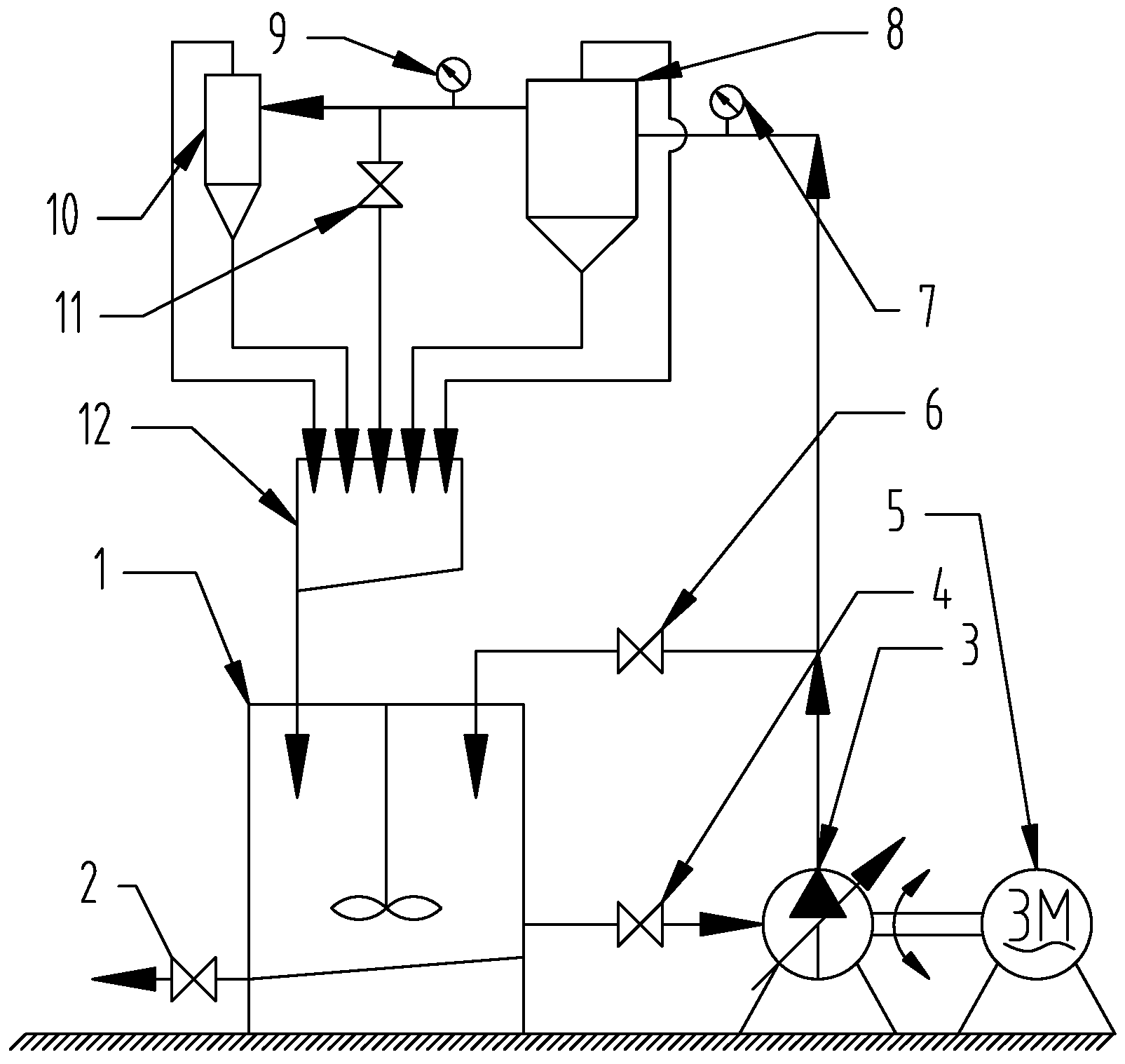
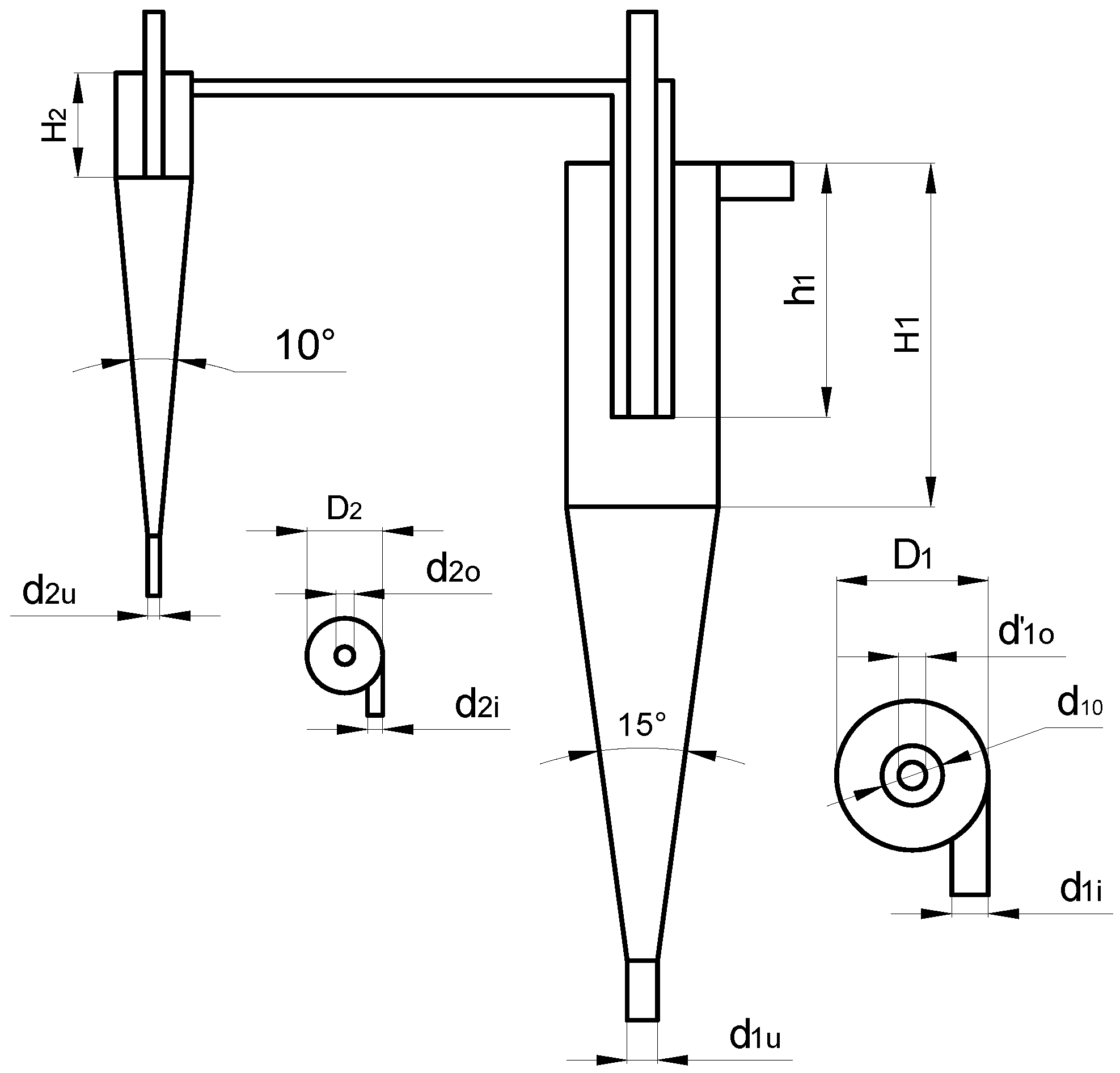
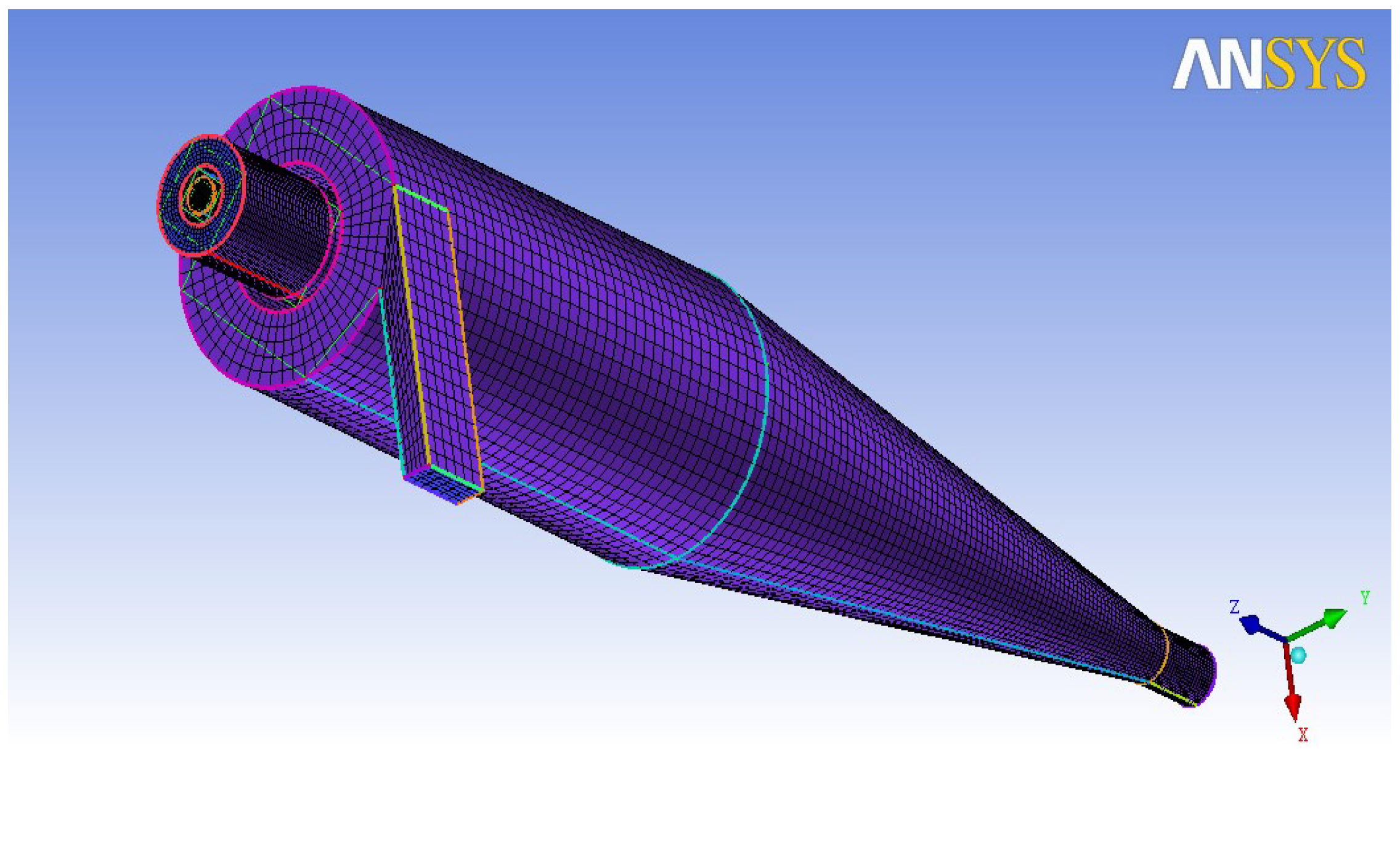
Summarizing the latest domestic and foreign research progress on hydrocyclone structure, the consistent conclusion is that the structural parameters, especially the diameter of the underflow outlet, are the main factors that affect the separation performance of the flow field. However, most of the previous research focused on the separation performance, which could not overcome the shortcomings of existing hydrocyclones in which one classification cannot satisfy the requirements for fine classification with narrow size fraction. The conventional hydrocyclone can only obtain two products through the overflow of the fine particles and underflow of the coarse particles. However, in addition to these two products, there must be an intermediate product between the fine particles and the coarse particles. If the intermediate product enters the underflow, it will cause a loss in concentration. And if the intermediate product enters the overflow, it will cause the concentrate pollution. Therefore, effectively processing the intermediate material to obtain multiple products with narrow size fractions through a single classification that further meets the requirement for the fine classification of the feeding materials in the following sorting operation is key to improving concentrate yield and grade. Thus, a two-stage multi-product hydrocyclone that operates in series was designed in this work. The first stage of the hydrocyclone was designed as a coaxial double-overflow-pipe structure. The finest particle is discharged from the internal overflow pipe and the particle with the intermediate size is discharged from the external overflow pipe, which then relies on the residual pressure to enter the second stage of the hydrocyclone for subsequent fine grading. Thus, a single classification can obtain multiple products with different size fractions resulting from the first stage underflow, first stage overflow, second stage underflow, and second stage overflow. However, due to the special structure of the double-overflow-pipe, the vortex domain, boundary layer and flow regime change. Therefore, it is necessary to study the flow field performance. In this study, numerical analysis and experimental methods were used to study the internal flow field characteristics of the double-overflow-pipe hydrocyclone and the particle size distribution characteristics of the different products. The influence rule of the diameter of the underflow outlet on the flow field and particle size fraction distribution was also studied in this work.

2. Materials and Methods

2.1. Multi-Product Hydrocyclone

In this study, a two-stage series multi-product hydrocyclone shown in Figure 1 was designed. The first stage of the hydrocyclone is designed as a coaxial double-overflow-pipe structure with different diameters, that is, a smaller diameter overflow pipe is coaxially inserted into the overflow pipe of the conventional hydrocyclone. The second stage of the hydrocyclone is designed as a conventional structure with the upper part as the column section and the lower part as the cone section. The external overflow pipe of the first stage is connected to the feed inlet of the second stage through a pipeline.
During operation of the designed hydrocyclone, the slurry enters the first stage of the hydrocyclone at a certain tangential speed and the particle classification occurs under the influence of the centrifugal force. The coarsest particle is discharged from the underflow outlet, and the finest particle is discharged from the internal overflow pipe. The intermediate-sized particle is discharged from the external overflow pipe and then enters the second stage of the hydrocyclone where the fine classification continues under the influence of the residual pressure. Through this classification process, which involve the first stage underflow, first stage overflow, second stage underflow, and second stage overflow, multiple products with different size fractions are obtained. The structural dimensions of the hydrocyclone used in this paper are shown in Table 1.

2.2. Numerical Analysis Method

In this work, considering the double-overflow-pipe hydrocyclone as the research object, the fluid dynamics analysis software FLUENT 6.3 is used to simulate the flow field characteristics of the hydrocyclone to study the influence rule of the diameter of the underflow outlet on the velocity field and pressure field. We use the ICEM 14.5 software for structural meshing. The result of the meshing is shown in Figure 2 and the total number of nodes of the entire flow field in the calculation field is 140,577.
The VOF two-phase flow model is used to represent the interface between air and water inside the hydrocyclone. The main phase is set as water and air is assumed to be the secondary phase. The Reynolds stress model (RSM) is used to represent the turbulence. A pressure-velocity coupling SIMPLE numerical method is used to calculate the control parameters. The pressure discretization format of the governing equation is the QUICK format. The fluid velocity at the inlet is 5 m/s, and it enters the hydrocyclone tangentially in a direction vertical to the inlet section. Set the overflow and underflow outlets as pressure outlets, and the wall of the hydrocyclone is represented by the standard wall function method. A pressure-based implicit transient 3D solver is used for the solution. The pressure gradient uses the Green Gaussian method to calculate the derivative term in the governing equation. The two-phase volume fraction uses the geo-reconstruct discrete format. The transient analysis uses explicit time discretization. The first order upwind scheme is adopted for modeling the turbulence kinetic energy, turbulence dissipation rate, and Reynolds stress discrete format.

2.3. Experiment Test Method

2.3.1. Experiment System

The experimental setup for testing the multi-product hydrocyclone is shown in Figure 3 and the schematic of the experiment is shown in Figure 4.
It is mainly composed of a slurry tank, stirrer, frequency conversion slurry pump, flow metering unit, and pressure measuring unit. Rotor flowmeters are installed at the feed inlet and overflow outlet of the system to obtain the feed and overflow discharges. The underflow discharge is calculated indirectly from the feed discharge and the overflow discharge. Pointer-type precision pressure gauges are installed at the feed inlet, underflow outlet, and overflow outlet to measure the pressure values at each portion of the hydrocyclone. The flow and pressure in the experiment system are controlled and regulated by the valves installed in the pump and pipe. Sampling ports are arranged at the inlet and outlet of the hydrocyclone, and the material property analysis can be done at any instance during the experiment process.

2.3.2. Experiment Material

The material used in the experiment is fly ash, which is tested and analyzed by the laser particle size analyzer (Malvern Mastersizer 2000, Malvern, Worcestershire, UK). The particle size component is shown in Table 2. The proportion of the particles with diameters less than 10 μm (1250 mesh) is 44.13%. The proportion of the particles with diameter less than 15 μm (800 mesh) is 53.11%. The proportion of the particles with diameter less than 44 μm (325 mesh) is 81.23%.

2.3.3. Experiment Design

The mass concentration of the fly ash slurry is taken to be 15%. During the experiment, the pressure gauge is adjusted through valves installed in the pump and pipe so that the feed pressure of the hydrocyclone is 0.16 MPa. The diameter of the internal overflow pipe of the hydrocyclone is 9 mm. The inserted depth of the internal overflow pipe is 85 mm. The diameter of the underflow outlet can be varied as 6 mm, 8 mm, 10 mm, 12 mm, and 14 mm. At the end of the experiment, the first stage internal overflow, first stage external overflow, first stage underflow, second stage overflow, and second stage underflow are sampled for the component analysis of the particle size fraction.

3. Results and Discussions

3.1. Numerical Simulation Results Analysis

3.1.1. Distribution Characteristics of Velocity Field and Influence of Underflow Outlet Diameter on Flow Field Performance

Figure 5 shows the tangential velocity distribution inside the hydrocyclone corresponding to different diameters of the underflow outlet. As shown in Figure 5, we can see that the tangential velocity at the center of the hydrocyclone is very small, and it increases with the radius of the hydrocyclone. When the diameter of the underflow outlet is reduced, the tangential velocity increases. This is because the smaller the diameter of the underflow outlet, the greater the resistance to the downward flow of the fluid and the lower the axial velocity. Therefore, when the feed pressure is kept constant, the tangential velocity is increased. From Figure 5, we can also conclude that the smaller the underflow outlet diameter, the closer the location of the maximum tangential velocity is to the center of the hydrocyclone; therefore, the greater the internal swirl centrifugal force, the better the separation performance and higher the classification accuracy.
Figure 6 shows the axial velocity field distribution. It can be seen that the axial velocity is in the shape of a broken line wave. Near the wall of the hydrocyclone, the axial velocity is downward. As the radius of the hydrocyclone decreases, the axial velocity shows an upward trend and traverses the zero point. After reaching a maximum value, the axial velocity begins to show a downward trend and again passes the zero point. Thus, along the radial direction, the axial velocity passes through the zero point twice, that is, the direction changes twice. This is due to the special double-overflow-pipe structure. Because there are two coaxial overflow pipes, two upward internal swirls exist in the internal and external overflow pipes, causing the direction of the axial velocity to change twice. This is different from the traditional hydrocyclone with a single overflow pipe where the distribution of the axial velocity is the inverted “W”.
As can be seen from Figure 6, in the double-overflow-pipe hydrocyclone, an area is formed between two zero axial velocity points. In this area, the axial velocity is small, which indicates that the position is not conducive to the separation of materials. Therefore, when designing a double-overflow-pipe hydrocyclone, we should try to avoid or reduce the range of this area by changing the structural parameters which will reduce the influence of this area on the separation efficiency of the hydrocyclone. From the influence rule of the diameter of the underflow outlet on the axial velocity, it can be seen that the axial velocity increases with the diameter of the underflow outlet. This indicates that increasing the diameter of the underflow outlet appropriately is beneficial to improving the classification efficiency.
Figure 7 shows the radial velocity distribution inside the hydrocyclone. We can see that the radial velocity of the fluid is the smallest at the wall which is close to zero. As the radius decreases, the absolute value of the radial velocity gradually increases. After reaching the maximum value, it gradually shrinks with the decrease in the radius. This is, in essence, consistent with the conclusion of the research by Ji et al. [39]. The diameter of the underflow outlet has little effect on the radial velocity field, which demonstrates that there is no essential difference between the double-overflow-pipe structure and the traditional single-overflow-pipe structure in terms of the radial velocity distribution.

3.1.2. Distribution Characteristics of Pressure Field and Influence of Underflow Outlet Diameter on Pressure Field Performance

Figure 8 shows the internal pressure field distribution of the hydrocyclone with double-overflow-pipe structure. The internal pressure decreases gradually from the wall to the axis, and it is symmetrically distributed at the center. The pressure near the axial direction is zero, and the nearer the point considered is to the central axis, the greater the negative pressure. From the simulation results, we can see that the hydrocyclone with double-overflow-pipe structure is very similar to the traditional hydrocyclone with a single-overflow-pipe structure in terms of the pressure distribution. We can also observe that the diameter of the underflow outlet has little effect on the pressure field. As the diameter of the underflow outlet increases, the pressure decreases slightly, but the change is not obvious.

3.2. Experiment Results Analysis

3.2.1. Influence of Underflow Outlet Diameter on Particle Size Fraction Component of First Stage Internal Overflow

Table 3 shows the particle size fraction component of the first stage internal overflow for different diameters of the underflow outlet, which are 6 mm, 8 mm, 10 mm, 12 mm, and 14 mm. From the Table 3, we can see that the internal overflow particle size decreases when the diameter of the underflow outlet decreases. When the diameter of the underflow outlet is 14 mm, D98 = 44.13 μm. When the diameter is 6 mm, D98 = 36.91 μm. The results show that proper reduction of the diameter of the underflow outlet is beneficial to obtain the first stage internal overflow product with finer particle size fraction.

3.2.2. Influence of Underflow Outlet Diameter on the Particle Size Fraction Component of First Stage External Overflow

Table 4 shows the particle size fraction component of the first stage external overflow with different diameters of the underflow outlet, which are 6 mm, 8 mm, 10 mm, 12 mm, and 14 mm. We can see from the Table 4 that the particle size of the first stage external overflow has a tendency to become thinner when the diameter of the underflow outlet increases. When the diameter of the underflow outlet is 6 mm, D98 = 51.23 μm. When the diameter is 14mm, D98 = 45.05 μm. This indicates that, for a multi-product hydrocyclone with the same specification, a proper reduction in the diameter of the underflow outlet is beneficial to obtain the first stage external overflow product with coarser particle size fraction.
Comparing Table 4 with Table 3, we can conclude that for the same diameter of the underflow outlet, the first stage external overflow particle size is slightly coarser than the first stage internal overflow particle size. This indicates that for a double-overflow-pipe hydrocyclone, we can obtain internal and external overflow products with two different particle size fractions. Meanwhile, we can see that the diameter of the underflow outlet has an opposite effect on the internal and external overflow particle sizes. That is, as the diameter of the underflow outlet increases, the first stage internal overflow particle size becomes coarser and the first stage external overflow particle size becomes finer. Based on this, we can adjust the diameter of the underflow outlet to obtain the internal and external overflow products having different particle sizes, which can further meet the requirements of the subsequent sorting operations on the particle size of the feeding materials.

3.2.3. The Influence of the Diameter of the Underflow Outlet on the Particle Size Fraction Component of the First Stage Underflow

Table 5 shows the particle size fraction component of the first stage underflow with different diameters of the underflow outlet, which are 6 mm, 8 mm, 10 mm, 12 mm, and 14 mm. From Table 5, we can see that the first stage underflow particle becomes finer when the diameter of the underflow outlet increases. When the diameter of the underflow outlet is 6 mm, D98 = 137.1 μm. When the diameter is 14 mm, D98 = 127 μm. This indicates that the proper reduction of the diameter of the underflow outlet is beneficial to obtain the first stage underflow product with coarser particle size fractions.

3.2.4. Influence of the Underflow Outlet Diameter on the Particle Size Fraction Component of Second Stage Overflow

Table 6 shows the particle size fraction component of the second stage overflow with different diameters of the underflow outlet which are 6 mm, 8 mm, 10 mm, 12 mm, and 14 mm. It can be seen from Table 6 that the change in the diameter of the underflow outlet has little effect on the particle size of the second stage overflow. When the diameter of the underflow outlet is increased from 6 mm to 8 mm, the particle size gradually becomes fine. On the other hand, when the diameter of the underflow outlet is increased from 10 mm to 14 mm, as the diameter increases, the particle gradually becomes coarse. This is because the first stage external overflow, which is the second stage feed material, becomes finer with the increase in the underflow outlet diameter. Generally speaking, the second stage overflow should show the same trend. However, in the practical experiment test, the second stage pressure decreases with the increase of the diameter of the underflow outlet, and the decrease of the pressure makes the second stage overflow become coarser. So, we can conclude that it is the result of the combination of these two factors.

3.2.5. Influence of Underflow Outlet Diameter on the Particle Size Fraction Component of Second Stage Underflow

Table 7 shows the particle size fraction component of the second stage underflow with different diameters of the underflow outlet which are 6 mm, 8 mm, 10 mm, 12 mm, and 14 mm. From Table 7 we can see that the second stage underflow particle size becomes finer when the diameter of the underflow outlet increases. When the diameter of the underflow outlet is 6 mm, D98 = 63.32 μm. When the diameter is 14 mm, D98 = 51.72 μm.
The size distribution results have shown that five distinct products can be produced by the two-stage series multi-product hydrocyclone, which is consistent with Mainza's results [30]. The difference is that we think that the diameter of first underflow port is an important factor affecting the size distribution, while Mainza et al. believe that the depth of insertion of overflow pipe is an important factor affecting the size distribution. The reason is that the pressure of the second stage of the two-stage multi-product hydrocyclone comes from the residual pressure of the first stage, and the diameter of the underflow port has a greater impact on the pressure.

3.2.6. Comparison of Particle Size Fraction Component of Different Products

Figure 9 shows the comparison of the maximum particle diameters of four products obtained from the first stage overflow, first stage underflow, second stage overflow, and second stage underflow. We can see that the proposed two-stage series multi-product hydrocyclone can obtain the products with different particle diameters after the separation. The maximum particle diameter of the first stage internal overflow is 44.13 μm. The maximum particle diameter of the first stage underflow is 127 μm. The maximum particle diameter of the second stage overflow is 44.95 μm. The maximum particle diameter of the second stage underflow is 51.72 μm.

4. Conclusions

In this study, a two-stage series multi-product hydrocyclone was designed so that different particle size fractions could be obtained as the first stage internal overflow, first stage external overflow, first stage underflow, second stage overflow, and second stage underflow after one classification.
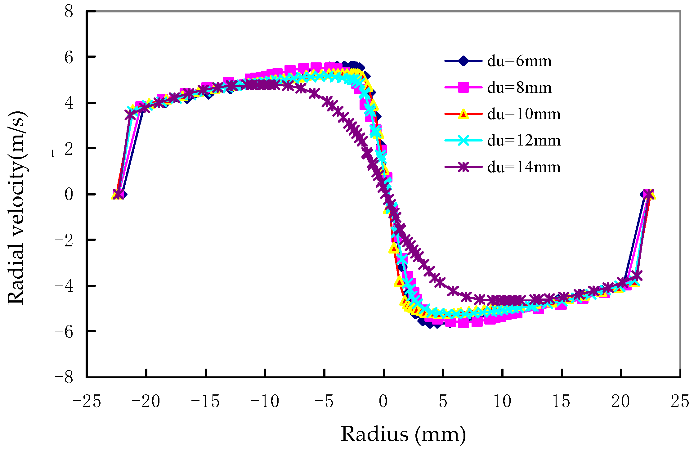
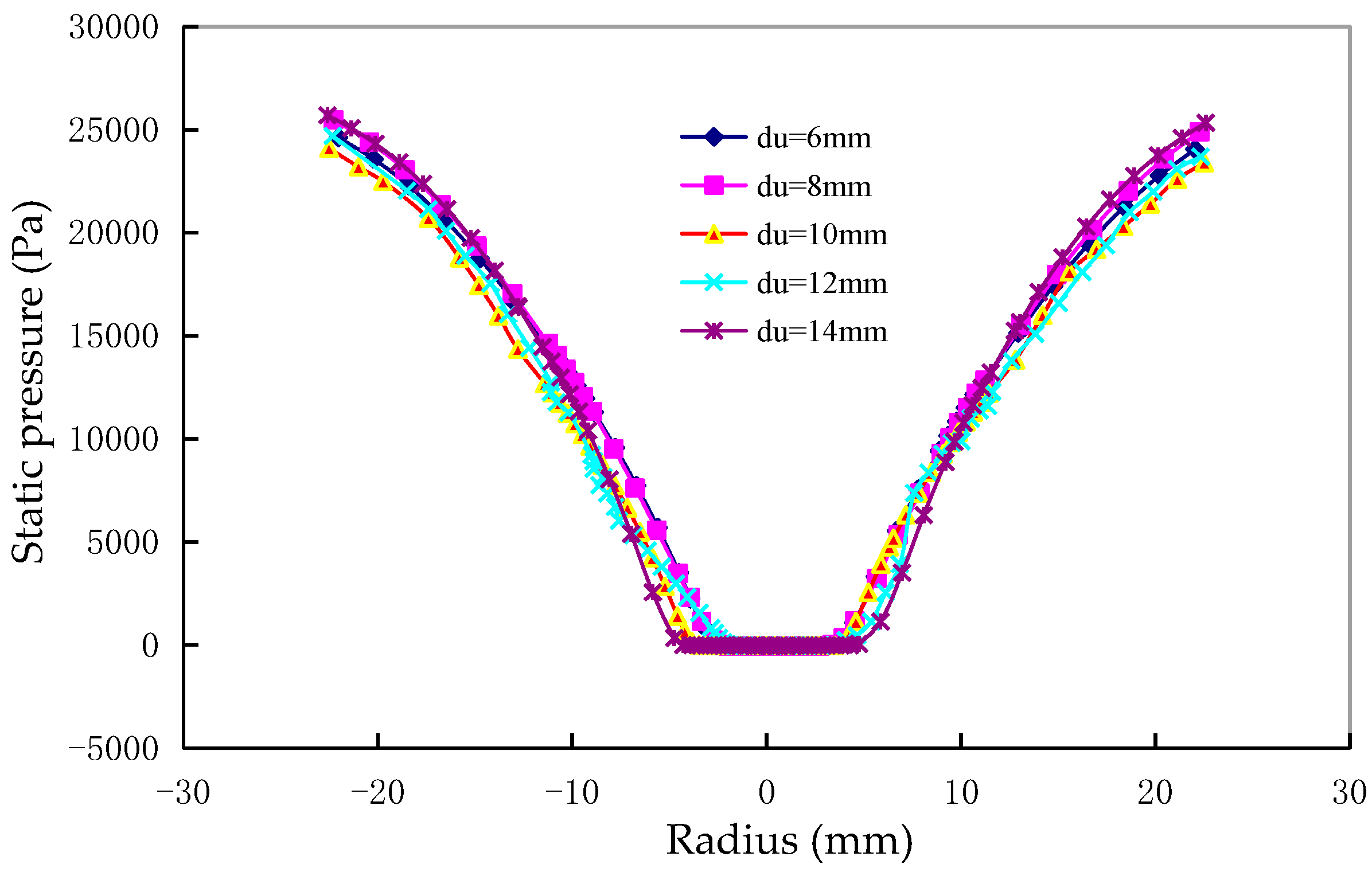
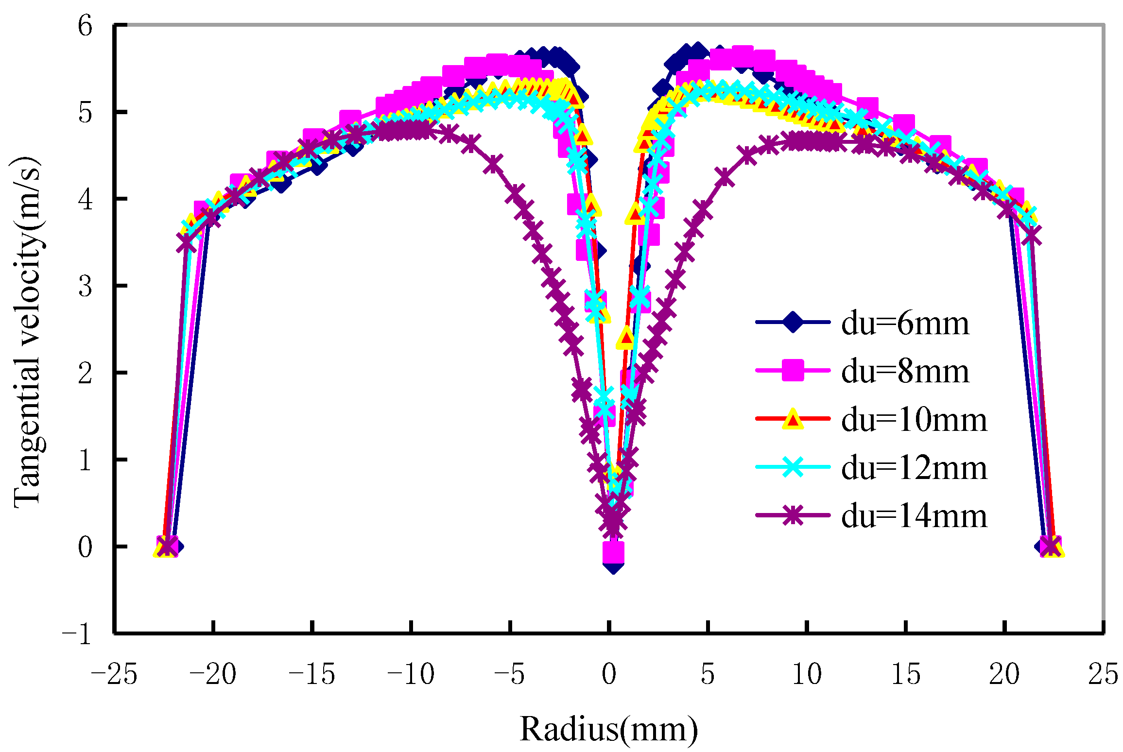
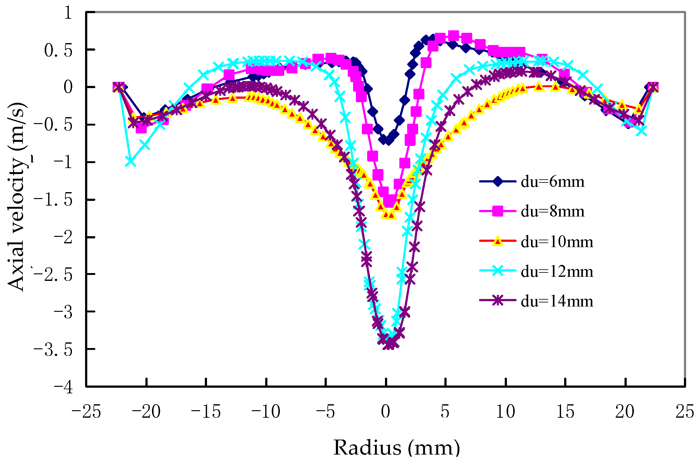
The axial velocity of the double-overflow-pipe changed direction twice along the radial direction, thus enclosing an area between the coaxial overflow pipes. The axial velocity was small in this area, which was not conducive to the particle separation. The diameter of the underflow outlet had little effect on the pressure field and radial velocity field, but had a greater influence on the tangential velocity and axial velocity. The axial velocity increased with the diameter of the underflow, which indicated that an optimal increase in the diameter of the underflow was beneficial to improving the classification efficiency. The tangential velocity increased with the decrease in the diameter of the underflow outlet, which was beneficial for increasing the centrifugal force of the internal swirl of the hydrocyclone, reducing the separation granularity, and improving the classification accuracy of the fine particles.
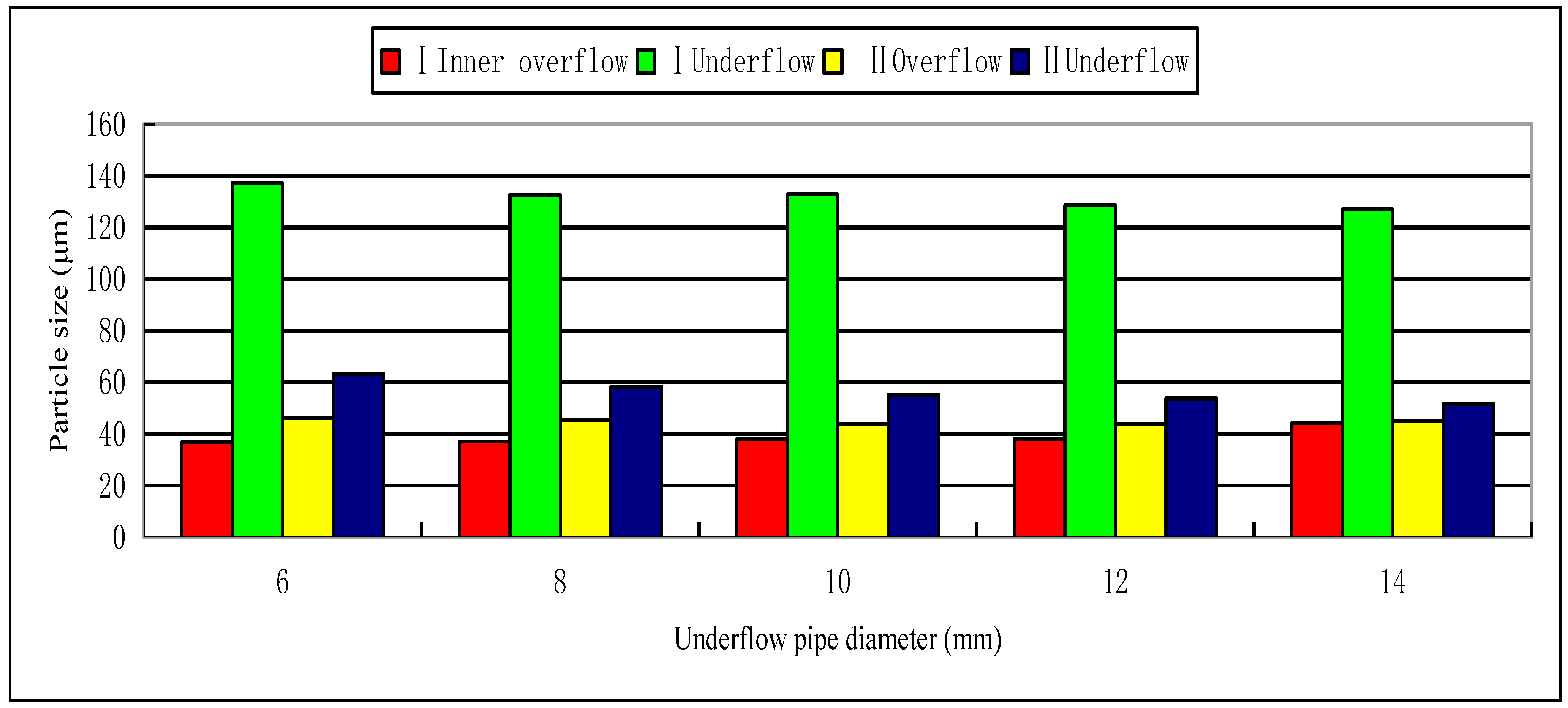
The first stage internal overflow was the finest while the first stage external overflow was the coarsest. The particle size of the second stage overflow was between that of the first stage internal and external overflows. The diameter of the underflow outlet had an opposite influence on the particle size of the first stage internal and external overflows. When the diameter of the underflow outlet increased, the particles of the first stage internal overflow became coarser and the particles of the first stage external overflow became finer.
The results of this study have a certain guiding role in the study of the flow field characteristics of the multi-product hydrocyclone. However, there are still many aspects that need to be addressed, such as the influence rule of the overflow pipe diameter and depth of insertion of the overflow pipe on the flow field and the distribution of the particle size fraction. In addition, the scale-up in engineering application is also an important issue to be discussed and highlight in the next step. These can be used to obtain the optimal structural parameters of the hydrocyclone for the best separation performance.

Author Contributions

Conceptualization, Y.Z.; Data curation, X.Y.; Formal analysis, Y.Z. and P.L.; Investigation, Y.Z. and L.J.; Methodology, Y.Z., P.L. and J.Y.; Resources, Y.Z.; Software, Y.Z.; Validation, L.J. and X.Y.; Writing—original draft, Y.Z.; Writing—review & editing, X.Y. and J.Y.

Funding

This research was funded by National Key R&D Program of China, 2018YFC0604702, Natural Science Foundation of Shandong province, ZR2016EEM37 and key research and development project of Shangdong province, 2017GSF216004.

Conflicts of Interest

The authors declare no conflict of interest.

References

  1. Svarovsky, L. Hydrocyclones; Holt, Rinehart and Winston: New York, NY, USA, 1984. [Google Scholar]
  2. Svarovsky, L. Solid-liquid Separation; Butterworths: London, UK, 1981. [Google Scholar]
  3. Narasimha, M.; Sripriya, R.; Banerjee, P.K. CFD modeling of hydrocyclone-prediction of cut size. Int. J. Miner. Process. 2005, 75, 53–68. [Google Scholar] [CrossRef]
  4. Liu, L.; Zhao, L.; Yang, X.; Wang, Y.; Xu, B.; Liang, B. Innovative design and study of an oil-water coupling separation magnetic hydrocyclone. Sep. Purif. Technol. 2019, 213, 389–400. [Google Scholar] [CrossRef]
  5. Silva, D.O.; Vieira, L.G.M.; Barrozo, M.A.S. Optimization of design and performance of solid-liquid separators: A thickener hydrocyclone. Chem. Eng. Technol. 2015, 38, 319–326. [Google Scholar] [CrossRef]
  6. Liu, P.-K.; Chu, L.-Y.; Wang, J.; Yu, Y.-F. Enhancement of Hydrocyclone Classification Efficiency for Fine Particles by Introducing a Volute Chamber with a Pre-Sedimentation Function. Chem. Eng. Technol. 2008, 31, 474–478. [Google Scholar] [CrossRef]
  7. Narasimha, M.; Mainza, A.N.; Holtham, P.N.; Powell, M.S.; Brennan, M.S. A semi-mechanistic model of hydrocyclones Developed from industrial data and inputs from CFD. Int. J. Miner. Process. 2014, 133, 1–12. [Google Scholar] [CrossRef]
  8. Huang, L.; Deng, S.; Guan, J.; Chen, M.; Hua, W. Development of a novel high-efficiency dynamic hydrocyclone for oil-water separation. Chem. Eng. Res. Des. 2018, 130, 266–273. [Google Scholar] [CrossRef]
  9. Xu, Y.-X.; Liu, Y.; Zhang, Y.-H.; Yang, X.-J.; Wang, H.-L. Effect of shear stress on deoiling of oil-contaminated catalysts in a hydrocyclone. Chem. Eng. Technol. 2016, 39, 567–575. [Google Scholar] [CrossRef]
  10. Chu, K.; Chen, J.; Yu, A.B.; Williams, R.A. Numerical studies of multiphase flow and separation performance of natural medium cyclones for recovering waste coal. Powder Technol. 2017, 314, 532–541. [Google Scholar] [CrossRef]
  11. Vehmaanperä, P.; Safonov, D.; Kinnarinen, T.; Häkkinen, A. Improvement of the filtration characteristics of calcite slurry by hydrocyclone classifification. Miner. Eng. 2018, 128, 133–140. [Google Scholar] [CrossRef]
  12. Mackay, I.; Mendez, E.; Molina, I.; Videla, A.R.; Cilliers, J.J.; Brito-Parada, P.R. Dynamic froth stability of copper flotation tailings. Miner. Eng. 2018, 124, 103–107. [Google Scholar] [CrossRef]
  13. Li, Y.; Liu, C.; Zhang, T.; Li, D.; Zheng, L. Experimental and numerical study of a hydrocyclone with the modification of geometrical structure. Can. J. Chem. Eng. 2018, 96, 2638–2649. [Google Scholar] [CrossRef]
  14. Neesse, T.; Dueck, J.; Schwemmer, H.; Farghaly, M. Using a high pressure hydrocyclone for solids classification in the submicron Range. Miner. Eng. 2015, 71, 85–88. [Google Scholar] [CrossRef]
  15. Yang, Q.; Lv, W.-J.; Shi, L.; Wang, H.-L. Treating methanol-to-olefin quench water by mini hydrocyclone clarification and steam stripper purification. Chem. Eng. Technol. 2015, 38, 547–552. [Google Scholar] [CrossRef]
  16. Vieira, L.G.M.; Silva, D.O.; Barrozo, M.A.S. Effect of inlet diameter on the performance of a filtering hydrocyclone separator. Chem. Eng. Technol. 2016, 39, 1406–1412. [Google Scholar] [CrossRef]
  17. Zhang, C.; Wei, D.; Cui, B.; Li, T.; Luo, N. Effects of curvature radius on separation behaviors of the hydrocyclone with a tangent-circle inlet. Powder Technol. 2017, 305, 156–165. [Google Scholar] [CrossRef]
  18. He, F.; Zhang, Y.; Wang, J.; Yang, Q.; Wang, H.; Tan, Y.H. Flow patterns in mini-hydrocyclones with different vortex finder depths. Chem. Eng. Technol. 2013, 36, 1935–1942. [Google Scholar] [CrossRef]
  19. Ni, L.; Tian, J.; Zhao, J. Experimental study of the relationship between separation performance and lengths of vortex finder of a novel de-foulant hydrocyclone with continuous underflow and reflux function. Sep. Sci. Technol. 2016, 52, 142–154. [Google Scholar] [CrossRef]
  20. Wang, B.; Yu, A.B. Numerical study of the gas-liquid-solid flow in hydrocyclones with different configuration of vortex finder. Chem. Eng. J. 2008, 135, 33–42. [Google Scholar] [CrossRef]
  21. Ni, L.; Tian, J.; Zhao, J. Experimental study of the effect of underflow pipe diameter on separation performance of a novel defoulant hydrocyclone with continuous underflow and reflux function. Sep. Purif. Technol. 2016, 171, 270–279. [Google Scholar] [CrossRef]
  22. Ghodrat, M.; Kuang, S.B.; Yu, A.B.; Vince, A.; Barnett, G.D.; Barnett, P.J. Computational study of the multiphase flow and performance of hydrocyclones: Effects of cyclone size and spigot diameter. Ind. Eng. Chem. Res. 2013, 52, 16019–16031. [Google Scholar] [CrossRef]
  23. Kılavuz, F.Ş.; Gülsoy, Ö.Y. The effect of cone ratio on the separation efficiency of small diameter hydrocyclones. Int. J. Miner. Process. 2011, 98, 163–167. [Google Scholar] [CrossRef]
  24. Zou, J.; Wang, C.; Ji, C. Experimental study on the air core in a hydrocyclone. Dry. Technol. 2016, 34, 854–860. [Google Scholar] [CrossRef]
  25. Zhao, L.; Jiang, M.; Xu, B.; Zhu, B. Development of a new type high-efficient inner-cone hydrocyclone. Chem. Eng. Res. Des. 2012, 90, 2129–2134. [Google Scholar] [CrossRef]
  26. Golyk, V.; Huber, S.; Farghaly, M.G.; Prolss, G.; Endres, E.; Neesse, T.; Hararah, M.A. Higher kaolin recovery with a water injection cyclone. Miner. Eng. 2011, 24, 98–101. [Google Scholar] [CrossRef]
  27. Yang, G.; He, L.; Shujun, B.; Fengshan, W.; Guoxing, Z.; Iei, Z.; Bo, Y.; Li, Z. Analysis and test of flow field of two-stage series downhole hydrocyclone. In Proceedings of the SPE Asia Pacific Oil & Gas Conference and Exhibition, Perth, Australia, 25–27 October 2016. [Google Scholar] [CrossRef]
  28. Huang, C.; Wang, J.-G.; Wang, J.-Y.; Chen, C.; Wang, H.-L. Pressure drop and flow distribution in a mini-hydrocyclone group: UU-type parallel arrangement. Sep. Purif. Technol. 2013, 103, 139–150. [Google Scholar] [CrossRef]
  29. Chen, C.; Wang, H.-L.; Gan, G.-H.; Wang, J.-Y.; Huang, C. Pressure drop and flow distribution in a group of parallel hydrocyclones: Z-Z-type arrangement. Sep. Purif. Technol. 2013, 108, 15–27. [Google Scholar] [CrossRef]
  30. Mainza, A.; Powell, M.S.; Knopjes, B. Differential classification of dense material in a three-product cyclone. Miner. Eng. 2004, 17, 573–579. [Google Scholar] [CrossRef]
  31. Mainza, A.; Narasimha, M.; Powell, M.S.; Holtham, P.N.; Brennan, M. Study of flow behaviour in a three-product cyclone using computational fluid dynamics. Miner. Eng. 2006, 19, 1048–1058. [Google Scholar] [CrossRef]
  32. Mokni, I.; Dhaouad, H.; Bournot, P.; Mhiri, H. Numerical investigation of the effect of the cylindrical height on separation performances of uniflow hydrocyclone. Chem. Eng. Sci. 2015, 122, 500–513. [Google Scholar] [CrossRef]
  33. Vakamalla, T.R.; Koruprolu, V.B.R.; Arugonda, R.; Mangadoddy, N. Development of novel hydrocyclone designs for improved fines classification using multiphase CFD model. Sep. Purif. Technol. 2017, 175, 481–497. [Google Scholar] [CrossRef]
  34. Huang, A.-N.; Ito, K.; Fukasawa, T.; Yoshida, H.; Kuo, H.-P.; Fukui, K. Classification performance analysis of a novel cyclone with a slit on the conical part by CFD simulation. Sep. Purif. Technol. 2018, 190, 25–32. [Google Scholar] [CrossRef]
  35. Zhou, F.; Sun, G.; Zhang, Y.; Ci, H.; Wei, Q. Experimental and CFD study on the effects of surface roughness on cyclone performance. Sep. Purif. Technol. 2018, 193, 175–183. [Google Scholar] [CrossRef]
  36. Misiulia, D.; Elsayed, K.; Andersson, A.G. Geometry optimization of a deswirler for cyclone separator in terms of pressure drop using CFD and artificial neural network. Sep. Purif. Technol. 2017, 185, 10–23. [Google Scholar] [CrossRef]
  37. Murthy, Y.R.; Bhaskar, K.U. Parametric CFD studies on hydrocyclone. Powder Technol. 2012, 230, 36–47. [Google Scholar] [CrossRef]
  38. Vakamalla, T.R.; Mangadoddy, N. Numerical simulation of industrial hydrocyclones performance: Role of turbulence modelling. Sep. Purif. Technol. 2017, 176, 23–39. [Google Scholar] [CrossRef]
  39. Ji, L.; Kuang, S.; Qi, Z.; Wang, Y.; Chen, J.; Yu, A. Computational analysis and optimization of hydrocyclone size to mitigate adverse effect of particle density. Sep. Purif. Technol. 2017, 174, 251–263. [Google Scholar] [CrossRef]
Figure 1. Schematic diagram of multi-product hydrocyclone.
Minerals 09 00300 g001
Figure 2. Mesh system used in the simulation.
Minerals 09 00300 g002
Figure 3. Schematic of the experimental apparatus. 1—Agitator; 2, 4, 6, 11—Valves; 3—Slurry pump; 5—Motor; 7, 9—Pressure gage; 8—I stage hycrocyclone; 10—II stage hydrocyclone; 12—Receiving vat.
Minerals 09 00300 g003
Figure 4. Schematic of the experimental site.
Minerals 09 00300 g004
Figure 5. Tangential velocity profiles at several spigot diameters.
Minerals 09 00300 g005
Figure 6. Axial velocity profiles at several underflow pipe diameters.
Minerals 09 00300 g006
Figure 7. Radial velocity profiles at several underflow pipe diameters.
Minerals 09 00300 g007
Figure 8. Static pressure profiles at several underflow pipe diameters.
Minerals 09 00300 g008
Figure 9. Comparison of maximum grain size products of different underflow pipe.
Minerals 09 00300 g009
Table 1. Specifications of the hydrocyclone used in this study.
Structural ParameterStructural Dimensions (mm)
Hydrocyclone body diameter D1 50
Inner vortex finder diameter d1o 6
Outer vortex finder diameter d1o 20
Underflow port diameter d1u 6, 8, 10, 12, 14
Feed inlet equivalent diameter d1i 12
Outer overflow pipe insertion depth h1 85
Hydrocyclone body diameter D2 25
Vortex finder diameter d2o6
Underflow port diameter d2u4
Feed inlet equivalent diameter d2i5
Cylinder height H1116
Cylinder height H2 35
Table 2. Particle size composition of coal ash.
Mesh NumberParticle Size (μm)Weight (%)Cumulative Weight (%)
−70 + 100−251 + 1470.15100
−100 + 200−147 + 747.2499.85
−200 + 270−74 + 537.4492.61
−270 + 325−53 + 443.9485.17
−325 + 450−44 + 328.5681.23
−450 + 800−32 + 1519.5672.67
−800 + 1250−15 + 108.9853.11
−1250 + 2500−10 + 515.0344.13
−2500 + 6250−5 + 21429.1
−6250−2 + 115.115.1
Table 3. Particle size of I inner overflow.
Underflow Diameter (mm)68101214Content (%)
Particle size (μm)0.5120.5210.5320.530.5623
0.8210.8650.860.8880.97410
3.5233.8964.1054.2665.37850
16.3516.9818.6518.6523.8390
36.9137.1437.938.1444.1398
Table 4. Particle size of I outer overflow.
Underflow Diameter (mm)68101214Content (%)
Particle size (μm)0.5540.5540.5570.5570.5473
0.9740.9670.950.970.93510
5.8425.4765.2095.0834.96950
27.224.4622.9522.3522.2590
51.2347.6446.0545.4545.0598
Table 5. Particle size of I underflow.
Underflow Diameter (mm)68101214Content (%)
Particle size (μm)0.8540.860.7480.7230.6793
3.3342.8072.2062.021.81410
32.2229.612724.3421.8850
94.890.5690.1586.0183.3690
137.1132.4132.8128.612798
Table 6. Particle size of II overflow.
Underflow Diameter (mm)68101214Content (%)
Particle size (μm)0.550.5530.5340.5440.5463
0.9750.9320.890.890.92810
5.3525.0164.4764.6714.67750
25.5722.3120.2921.0222.0190
46.345.2643.8143.9844.9598
Table 7. Particle size of II underflow.
Underflow Diameter (mm)68101214Content (%)
Particle size (μm)0.5580.5550.5490.5390.543
1.1981.051.11.0251.01710
8.2137.6846.7216.7096.6650
32.7629.5529.228.9427.6190
63.3258.2655.1653.6951.7298

