Abstract
Backfilling mining is thought to play a significant role in controlling the deformation of coal and rock strata and the distribution of underground pressure. This study presents a numerical investigation of the influence of the strength of backfilling materials (BMS) on the deformation of coal and rock strata consisting of multiple goaf during excavation using the backfill mining method. In this study, a numerical three-dimensional fast Lagrangian analysis of continua (FLAC 3D) model was constructed to explore the relationship among the BMS, the displacement of coal and rock strata, and the distribution of underground pressure based on the geological conditions of a mining panel of the Hengda coal mine in the City of Fuxin, China. The numerical results suggest that as the BMS increase, the supporting ability of backfilling materials in goaf becomes stronger. At the same time, when the displacement of coal and rock strata decrease, the pressure on the surrounding rocks decreases and the pressure on the overlying stratum increases. However, the effect of BMS on the coal and rock strata has a limit. When the BMS equals and/or exceeds that of coal, the influence is not obvious. In addition, the displacement and underground pressure in the surrounding goaf are also affected, but in a relatively gentle way. Moreover, during the process of mining, as the BMS increases, the scope and arch area of the underground pressure in front of working face decrease instead. The higher the BMS is, the more stable the main key stratum is. The ability to resist compressional deformation of backfilling materials plays an important role in controlling the displacement of roof and relieving the underground pressure on the overlying stratum. Thereby, the roof stability in front of the working face is helpful for safety in the production of coal mines.
1. Introduction
Roof collapse accidents have been a major safety concern in underground coal mines in China for more than 50 years. A roof collapse accident refers to the natural collapse of upper coal and rock strata, breaking the original energy balance in underground mining [1]. It can cause fatalities, injuries, and significant economic loss for coal mining industries. Roof collapse accidents occur more frequently in goaf of coal mines, where they are not backfilled or are backfilled with materials having insufficient strength. Therefore, studying the strength of backfilling materials (BMS) is important to ensure coal mine safety and productivity.
As a supporting structure, backfilling materials bear most of the load from the overburden stratum of goaf. It can change the stress state of the surrounding rock of stope, and reduce the collapse of surrounding rocks and the development of fracture zones. In backfilling mining, the primary objective is to design the BMS, and thus to control the stability of surface subsidence and mine seams and to prevent damage of the surface or near-surface features (e.g., buildings, railways, highways, rivers, pipelines, etc.) [2,3]. Numerous studies have been conducted to obtain comprehensive understanding in the proper design of backfilling mining technology. The design of backfilling mining must consider the BMS, the activity features of the overlying stratum in the backfilling and mining field, and the theory of mine pressure control [4,5]. Miao et al. developed a comprehensive mechanized filling coal mining technology which could control the movement of rock stratum and surface subsidence by controlling the backfill rate in goaf [6,7,8,9]. Based on the systematic study of the compaction of waste rock backfilling materials and time correlation, Zhang et al. [10,11,12,13,14,15,16] presented an equivalent height model for analyzing the law of mining pressure by filling the goaf with waste rocks. He also obtained the supporting strength in fully mechanized mining and the correction coefficient of filling mining with traditional fully mechanized support strength. By means of analogue and numerical simulations, Chang et al. analyzed the deformation of roof stratum and the distribution of underground pressure during filling mining [17,18]. Liu et al. studied the influence of the compressional ratio of backfilling materials on the activity features of overlying key stratum. Their results suggest that the greater the compressional rate is, the longer the period required for stability of the rock stratum is, and the more active the range and activity of the rock stratum are, which is not conducive to controlling the stability of the rock stratum [19,20,21].
The ability to resist the compressional deformation of backfilling materials is directly related to the movement and subsidence of coal and rock strata. To investigate the factors affecting the BMS, Huang et al. tested the strength of waste rocks, and the results showed that BMS directly affected the backfill rate of goaf [22,23,24]. When the backfill rate increases, the movement of overlying stratum decreases and the underground pressure increases. However, in these studies, they did not give a detailed investigation or provide conclusions as to how the BMS affects the movement of overlying stratum and the distribution of underground pressure.
Both empirical and theoretical methods have been applied to explore the relationship between the BMS, the deformation of surrounding rock, the distribution of underground pressure, and the stability of coal and rock strata [25,26,27,28]. However, the influence of the BMS on the deformation of coal and rock strata and the evolutionary law of underground pressure remains largely unexplored in the literature. Therefore, in this study, a three-dimensional fast Lagrangian analysis of continua (FLAC 3D) model was built to understand the effect of the BMS on the distribution of underground pressure and the deformation of coal and rock strata according to the geological conditions of the Hengda coal mine in the City of Fuxin, China.
2. Numerical Model and Governing Equations
2.1. Geological Summary of Hengda Coal Mine
Hengda coal mine has a danger of rock burst. It is located in Fuxin City, China (Figure 1). There is a stratum of sandstone pseudo-top above the roof of the 5366 working face, with a thickness of 0.1–0.5 m. Above it, the main roof is about 17–38 m thick and made of siltstone, ash, and coal. The 5330 and 5332 goafs are located to the north of the 5366 working face. The 4301, 4302, and 4303 goaf areas are above the working face, with a vertical distance about 28–46 m. The surface area of the working face is 360 m × 120 m. The average thickness of the coal seam is 10 m. The working face is inclined mining, with a 4° inclination [29].
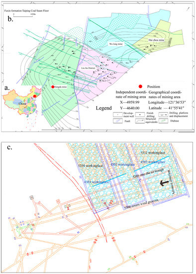
Figure 1.
Geological information of Hengda coal mine. (a) Location of Hengda coal mine; (b) Geological boundary of Hengda coal mine; (c) Simplified layout of 5366 working face.
It is crucial to properly assess the properties of surrounding rock to obtain accurate parameters for numerical modeling. Therefore, the physical and mechanical properties of each geological unit must be determined. In general, the properties of surrounding rocks can be determined by laboratory test. The samples described above were obtained from exploration drilling, and rock blocks were taken directly from the Hengda coal mine. According to the available literature, the uniaxial compressive strength, Young’s modulus, Poisson’s ratio, cohesion, and friction angle of coal and rock are needed for modelling the mechanical state of the coal and rock strata in this study. Uniaxial compression tests were carried out to determine the uniaxial compressive strength, Young’s modulus, and Poisson’s ratio. The cohesion and friction angle of the surrounding rocks were obtained by triaxial compression tests. Based on the results of these tests, the panel stratigraphy and other important geotechnical parameters of the coal seam, roof, and floor strata are shown in Figure 2.
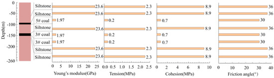
Figure 2.
Simplified panel stratigraphy and geotechnical parameters of the seam, roof, and floor strata.
2.2. Numerical Model and Method
In this study, FLAC 3D was used to construct a model for simulating the distribution of underground pressure and the deformation of rock stratum on the basis of the geological conditions of the Hengda coal mine. The numerical model was set to 800 m × 500 m × 260 m, the dip angle of strata was set to 4°.
In the model, the 5366 working face was chosen as the study area. The model’s parameters, roadway layout, and working faces are shown in Figure 3. The length of the 5366 working face is 390 m and the width is 120 m. The thickness of the coal seam was set to 3 m and the burial depth was set to 147 m for the numerical model. According to the actual situation of the Hengda coal mine, 5 goafs were arranged. The width of the coal pillar between the goafs was 20 m. To obtain the distribution of the underground pressure in the panel, boundary conditions were established for the numerical model. The horizontal displacement of the four vertical walls of the model were constrained in the normal direction, and the vertical displacement at the base of the model was set to zero. At the top of the model, a vertical load of (P = γ∙h) 23 MPa was applied to simulate the overburden weight, which was equal to the equivalent gravity of the above coal and rock strata. Based on extensive data of crustal stress collected from the Hengda coal mine, both stress coefficients in x- and y-directions (horizontal plane) were set to 1.0. The elastoplastic Mohr–Coulomb model with no associated flow rules was chosen as the failure criterion for modelling the coal, roof, and floor strata. The mechanical parameters used in this simulation are shown in Figure 2.
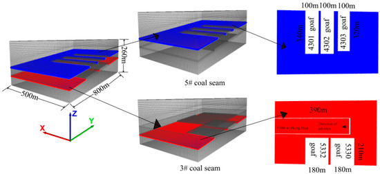
Figure 3.
Sketch of the three-dimensional fast Lagrangian analysis of continua (FLAC 3D) mesh for all panels.
2.3. The Execution of FLAC 3D Governing Equations
When the Mohr–Coulomb model runs in FLAC 3D [30,31], first the stress increment calculated by Hooke's law is superimposed on the original stress (), and the principal stress can be calculated. If the principal stress reaches the failure criterion, shear failure and/or tensile failure will occur in the model, as shown in Figure 4 [30]. Flow laws are calculated corresponding to different forms of failure, and the is obtained as shown in Figure 5 [30]. If the stress point (, ) in the (, ) plane lands on the envelope inside, then it shows that there is no plastic flow in this step, and the new principal stress is , I = 1,3.
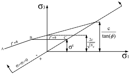
Figure 4.
FLAC 3D Mohr–Coulomb damage criterion.
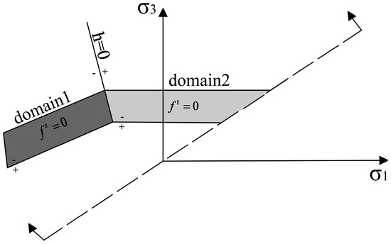
Figure 5.
Mohr–Coulomb model flow rule.
3. Analysis of Numerical Simulation Results
3.1. Movement Laws of Coal and Rock Strata
The BMS is directly related to the controlling effect of the movement of coal and rock strata and the subsidence of the land surface. In order to study the influence of the BMS on the movement of coal and rock strata, the coal seam was mined for 390 m, with the assumption that the filling process finished immediately after the excavation. The initial filling height was set to 100%. The BMS was set to 0.05, 0.1, 0.2, 0.3, 0.5, 1, 1.5, and 2 times the strength of coal, respectively. The displacement of strata and the underground pressure over the process of excavation was analyzed.
After reaching the convergence of the model, the processes of excavation and backfilling were sequentially simulated. Each mining stage was excavated for 10 m. After the excavation of the coal seam, the required time for deformation and stress release was ignored. The processes of filling materials finished, and the filling length was 5 m. The backfilling materials were supposed to reach the designed strength instantly. According to the observation line installed in the model, the displacement of overlying coal, rock, coal pillar, and surrounding goaf was studied. In light of the monitoring data, the displacement of different points employing the different BMS were drawn, which is shown in Figure 6 and Appendix A Figure A1, Figure A2 and Figure A3.
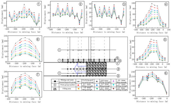
Figure 6.
Movement characteristics of the coal and rock strata (360 m).
As shown in Figure 6 and Appendix A Figure A1, Figure A2 and Figure A3, the displacement of coal and rock strata after mining presented a certain rule, showing that the subsidence slowly increased at first, reached the maximum subsidence value, and decreased slowly in the end. The maximum subsidence of the overlying strata occurred in the middle of the goaf. The range, reaching the maximum subsidence, was within the 50–200 m away from the open-off cut. Then, the displacements at different positions were compared. For the displacements observed at the coal mining face, the coal pillar, and the overlying strata, the maximum displacements were 43.86 mm, 98.02 mm, 268.81 mm, and 55.42 mm, respectively; the minimum displacements were 14.39 mm, 41.79 mm, and 168.61 mm, respectively; and the displacement change percentages were 67.18%, 57.37%, and 37.27%.
In addition, the analysis of different positions was carried out one-by-one. The results showed that the displacement of coal and rock strata increased periodically and decreased after the backfilling process. With the increase of the BMS, the increase speed and the increase rate of displacement also showed a decreasing tendency. At the same time, it was found that backfilling mining had an influence on the movement of the overlying coal and rock strata in front of the working face, and the range of influence was about 100 m in front of working face, the fluctuation within this range was 5–40 m. The stronger the anti-deformability was, the smaller the displacement and affected areas were. The displacement in the overlying stratum reached 266.81 mm, 249.69 mm, 229.17 mm, 216.49 mm, 200.81 mm, 182.28 mm, 173.70 mm, and 168.61 mm when the BMS was set to 0.05, 0.1, 0.2, 0.3, 0.5, 1.0, 1.5, and 2.0, respectively. The biggest changing rate for the displacement gradually reduced from 20.52 mm to 5.08 mm. When the BMS was more than 1 times the strength of coal, the displacement of overlying coal and rock strata was close to 0. From the perspective of surrounding rock and pillar, after the mining, the displacement reached an equilibrium state. The closer the position of the distance to the open-off cut was, the greater the change of the displacement was. Meanwhile, with the increase of the BMS, the change value of the vertical displacement decreased, and the time required for stability shortened. In addition, surrounding goafs are also affected to varying degrees. The closer the mining coal seam was, the more obvious the displacement of the surrounding goaf changes. At the same time, the displacement of the surrounding goaf decreased with the increase of the BMS. However, this change in displacement was only about 50% compared to that at the coal mining face.
In the process of advancing the working face, the displacement increased. However, the changing process of the overall displacement of the working face was relatively slow. In the range of 100–200 m away from the working face, the vertical displacement of each point reached the maximum. According to the observed curves when using the different BMSs, the subsidence of the working face and the surrounding rocks decreased with the increase of the BMS. When the BMS was low (about 0.5 times), the displacement increased at each point and the maximum value was up to 140 mm. When the BMS increased (about 1 times), the vertical displacement increased, only about 40 mm. With further increases of the BMS, the vertical displacement did not show obvious change. However, the changes in displacement in the surrounding goaf were less dramatic. With the advancement of the working surface, the displacement gradually increased. When the working face was pushed to the boundary of the goaf, the displacement surged. As the working surface continued to advance, the goaf gradually reached a balance in the displacement.
3.2. Analysis of Underground Pressure
Underground pressure is a key factor in controlling the change of vertical displacement. Therefore, to further study the influence of the BMS on the underground pressure during the mining process, the coal seam was mined for 390 m, with the assumption that the filling process finished immediately after the excavation. The initial filling height was set to 100%. The BMS was set to 0.05, 0.1, 0.2, 0.3, 0.5, 1, 1.5, and 2 times the strength of coal, respectively. According to the simulation results, the vertical stress when using the different BMSs are shown in Figure 7 and Appendix A Figure A4, Figure A5 and Figure A6.
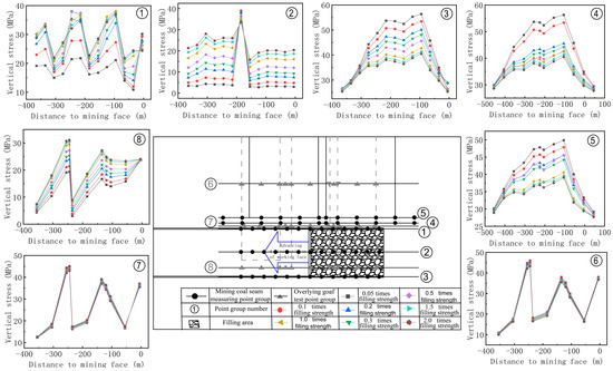
Figure 7.
Distribution of the underground pressure.
From Figure 7 and Appendix A Figure A4, Figure A5 and Figure A6, by analyzing the underground pressure changes in the roadway of coal and rock after mining, the underground pressure of the whole mining face displayed a zigzag style, meaning that the pressure of the roadway presented a periodically increasing and decreasing trend. The maximum underground pressures were all observed in the middle of the goaf. The stress peak was within the range of 50–150 m from the distance away from the open-off cut. Comparing the distribution of the underground pressure at different locations, it was found that the maximum pressure of the coal seam, the coal pillar, and the overlying strata using the different BMSs was about 28.05 MPa, 56.29 MPa, and 46.02 MPa, respectively. The minimum underground pressure was 2.67 MPa, 28.54 MPa, and 3.99 MPa. The pressure in the goaf was generally stable, but there was some stress concentration. As the BMS increase continued, the peak and influence range of the stress of the top plate in front of the working face gradually decreased. However, when exceeding a certain range, the change of the underground pressure was not obvious. The underground pressure of the overlying stratum reached 3.71 MPa, 6.33 MPa, 10.14 MPa, 12.81 MPa, 16.44 MPa, 21.40 MPa, 24.15 MPa, and 26.04 MPa when the BMS was set to 0.05, 0.1, 0.2, 0.3, 0.5, 1.0, 1.5, and 2.0, respectively. The variation in the underground pressure also decreased from 4.96 MPa to 1.89 MPa. When the BMS was more than 1 times the strength of coal, the pressure changes were not obvious. Regarding the pressure in the surrounding rock pillar, the curve of the pressure presented an arch trending style; that is, it gradually increased and then decreased. At the same time, as the BMS increased, the pressure in the surrounding rocks also decreased, and the arch area of underground pressure decreased (③–⑤ in Figure 7). Besides, to varying degrees, the surrounding goaf was also affected. The closer the coal seam was, the more obvious were the underground pressure changes in the surrounding goaf. At the same time, with the increase of the BMS, the underground pressure in the surrounding goaf decreased.
With the advancement of the filling working face, the stress concentration area in front of the working face and the stress reduced area of the arch behind the working face also moved forward. However, the scope and peak value of the stress concentration in front of the working face were small. The width and height of the stress reduced area of the arch behind the working surface continuously increased, but the range decreased as the BMS increased. The underground pressure rose at a relatively gentle rate. In the surrounding mined area, the change in the underground pressure was not as significant, but the general law was consistent with that at the working face. With the advancement of the working face, the underground pressure in the surrounding goaf gradually increased. When the working face advanced to the boundary of the goaf, there was a sharp increase in the underground pressure. As the working face continued to advance, the goaf gradually reached a state of equilibrium with a decline and stabilization in the underground pressure.
4. Discussion
4.1. Beam Theory of Elastic Foundation
According to the results, during the process of mining, the change law of the displacement using the different BMSs was summarized. To study the relationship between the BMS and the deformation of coal and rock strata in the process of mining, 1 times strength of coal was chosen as a research object. The measurement points were arranged in the working face to monitor the displacement during the backfilling process. The displacement curve and the corresponding images are shown in Figure 8.
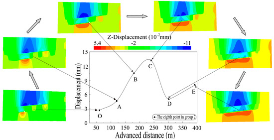
Figure 8.
The change law of the displacement over the process of backfilling mining.
From Figure 8, in the process of mining and backfilling, the displacement of the overlying stratum first increased, reached the peak value gradually, then decreased and eventually remained stable. There was no sharp increase in this period, and the growing rate was relatively slow. This was due to the support of the backfilling materials to the overlying stratum, which effectively controlled the collapse of the overlying stratum. The reason for the curve over 300 m (DE stage in Figure 8) might be the continuous increase of the working face length, which resulted in the increase of the underground pressure on the backfilling materials. When it was beyond the BMS, the backfilling area was destroyed and fractures again appeared in the overlying stratum. This indicates that the BMS has an important influence in controlling the deformation of the coal and rock strata. To analyze the supporting effect of the backfilling materials to the roof, a mechanical model based on the Winkler elastic foundation beam with roof was established, as shown in Figure 9 [32,33,34].
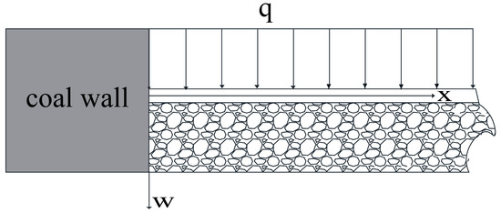
Figure 9.
Structural mechanics model.
According to the principle of waste rocks backfilling and the structures of the roof stratum, coal wall, and working face after backfilling, it is reasonable to assume that the backfilling materials of the model were fully connected to the roof of the coal seam [35,36,37,38,39]. The bearing capacity of the roof of the overlying stratum is q. The differential equation of the Winkler elastic foundation rock beam on the unit width is obtained as follows:
where EI is the flexural stiffness of rock beam, q is the uniformly distributed load, K is the coefficient of filling foundation, W is the rock beam deflection.
Based on the mechanical properties of the materials, there were the following differential relations between the angle M of any point of the beam, the bending moment and the shear q, and the deflection w:
combining the following boundary conditions:
The deflection equation can be obtained as follows:
from Equation (4), it can be seen that when the plate stiffness EI is constant, the greater the K is, the greater the is. That is, the top slate beam reaches the maximum deflection at the point closest to the coal wall. The final deflection value of the roof beam is also changed. In addition, the greater the BMS and the greater the K value are, the smaller the deflection of the top slate beam is.
4.2. The Effect of the Elastic Core of Backfilling Materials
Previous studies have shown that the deformation of coal and rock strata is related to the uneven distribution of underground pressure in coal mines [40,41,42]. To further study the displacement changes of overlying stratum, it is necessary to analyze and study the change law of underground pressure during the mining process. In this study, we took the BMS as 1 times the strength of coal as a research object, and chose the initial mining area as the monitoring area. The stress variation curve and the corresponding cloud chart of stress distribution are shown in Figure 10.
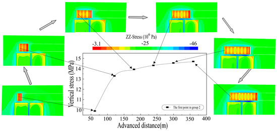
Figure 10.
The change of the underground pressure over the process of mining.
It can be obtained that the underground pressure on the coal pillar was larger than that around the working face. The pressure on the overburden strata fluctuated periodically after backfilling. The reason for the cyclical changes in the distribution of stress was probably due to the interaction time between the backfilling materials and the roof, and the backfilling range of the working face. At the beginning of backfilling mining, the backfilling materials were compressed, and they were unable to bear too much pressure. Therefore, most of the stress would be transformed to the surrounding rocks and coal pillars. As the backfilling process continued, the backfilling materials were subjected to some pressure. As the time of compression was different, there was no backfilling in the range of open-off cut about 5 m in the goaf. The distribution of the underground pressure was uneven and periodic fluctuation appeared. Moreover, the closer the distance from the open-off cut was, the smaller was the underground pressure. This indicates that the backfilling materials effectively bore most of the load of the overlying strata, which greatly limited the subsidence of the roof and relieved the appearance of the underground pressure.
After backfilling, the supporting pressure on the backfilling materials increased with the advancement of the working face. During the process, the law of change can be divided into three stages: initial stress region, stress increase region, and stable stress region. The extent of these three stages decreased with increasing BMS for the goaf. That is, the higher BMS in the goaf is, the shorter the stress stability period of backfilling materials is. In the initial stress region, the stress of the backfilling materials changed, but there was no phenomenon showing an increase in the underground pressure, indicating that the settlement of the roof in the initial stress area after backfilling was small. In the stress increase region, the stress in the backfilling materials gradually increased with a relatively slow rate, indicating that the roof of the goaf was gradually bent down and the backfilling materials were gradually compacted. The overall bending and subsidence of the overlying strata became stabilized under the support of the backfilling materials, and the pressure on the backfilling materials reached the maximum value, which was close to the initial rock stress.
4.3. Effect of the Strength of the Backfilling Materials on Roof Caving
In order to further analyze the controlling effect when using the different BMSs on the movement of coal and rock strata during the process of backfill mining, the displacement cloud charts were compared and analyzed, as shown in Figure 11.
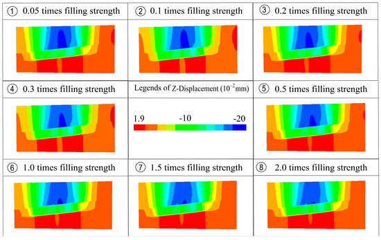
Figure 11.
Cloud map of displacement with different strengths of backfilling materials (BMSs).
Combined with the deformational characteristics of the overburden rock (Figure 10), when the BMS was low (①–③ in Figure 10), the backfilling materials did not play a supporting role. The immediate roof collapse with advancing the working face further resulted in the main roof caving, eventually leading to the main key stratum break, and collapse. With the increase of the BMS (④–⑤ in Figure 10), although the overburden roof still collapses, the backfilling materials could play a significant role in supporting the overburden roof. The key stratum bent and sunk, but no breakage was observed. When the BMS reached a certain limit (⑥–⑧ in Figure 10), the main materials filled could bear the overburden load in the goaf, limiting the subsidence and break of the immediate roof and main roof. Some local cracks were observed. This indicates that the backfilling materials effectively controlled the movement and deformation of the overlying strata and greatly reduced the underground pressure in the working face.
5. Conclusions
In this paper, backfilling mining with multiple goafs was simulated, and the influence of using different BMSs on the deformation of overlying rock and coal strata were analyzed. Some main conclusions can be summarized as follows:
- 1)
- The overburden rock movement was simulated during backfilling mining with FLAC 3D. At first, the BMS effectively improved the backfilling effects. Then, it was concluded that when the BMS was less than 0.5, breakages occurred in the main key stratum. When the BMS was 0.5 times the strength of coal, the roof caved and broke, without collapse. When the BMS was 1.0 times the strength of coal, the main roof working face and above overburden existed only continuous bending deformation without failure. Next, the displacement in front of the working face was also affected. With the increase of the BMS, the roof displacement of the working face decreased, the affected area shrank, and the roof of the coal seam was more stable. Finally, as the BMS increased, the findings show that the surrounding goaf was also influenced.
- 2)
- The BMS had a significant influence on the peak value and the influence range of the advance support stress, the arch area of the stress reduction in the overburden strata, and the stress stability period of the filling materials. As the BMS increased, the pressure on the surrounding rocks decreased and the pressure on the overlying stratum increased. On the other hand, with increasing BMS, the influence range and arch area of the underground pressure in front of the working face decreased. The higher the BMS was, the overburden strata could bear more underground pressure. Additionally, the shorter the time needed for the underground pressure to reach stability, the longer the time required for reaching the steady state of the coal mine.
- 3)
- The underground pressure and the displacement of the coal and rock strata affected each other. The increase of the underground pressure led to crack growth and resulted in collapses on the roof of the overlying stratum. In return, the change of the displacement made the underground pressure redistribute and achieved a new balance. Improving the BMS can maintain the stability of the underground pressure and prevent roof collapse and other accidents, and thus could provide a safe environment for backfilling mining.
Author Contributions
X.F. and Q.Z. contributed equally to this work.
Funding
This research was funded by the Fundamental Research Funds for the Central Universities grant number 2018QNB01; and funded by the Priority Academic Program Development of Jiangsu Higher Education Institutions (PAPD).
Acknowledgments
This project is supported by “The Fundamental Research Funds for the Central Universities” (2018QNB01) and funded by the Priority Academic Program Development of Jiangsu Higher Education Institutions (PAPD).
Conflicts of Interest
The authors declare no conflict of interest.
Appendix A
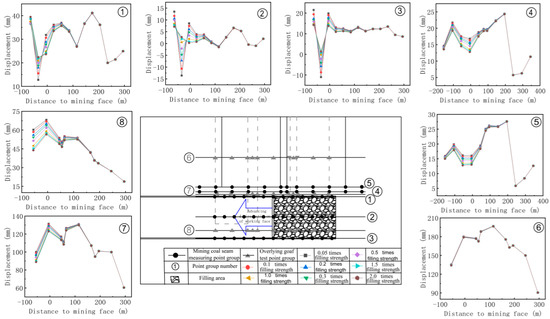
Figure A1.
Movement characteristics of coal and rock strata (60 m).
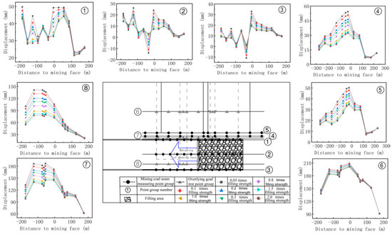
Figure A2.
Movement characteristics of coal and rock strata (180 m).

Figure A3.
Movement characteristics of coal and rock strata (300 m).
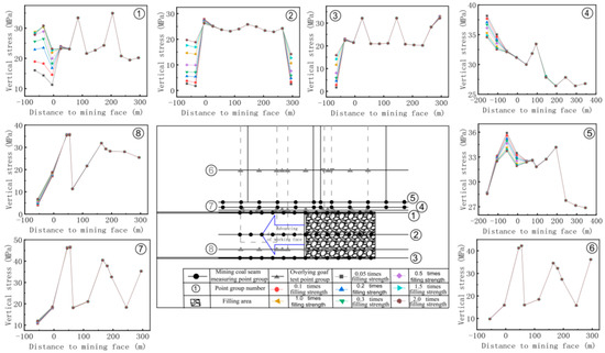
Figure A4.
Distribution of the underground pressure (60 m).
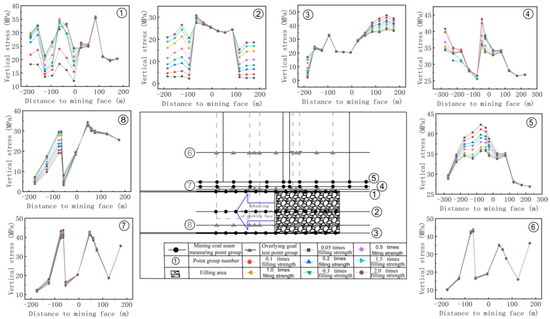
Figure A5.
Distribution of the underground pressure (180 m).
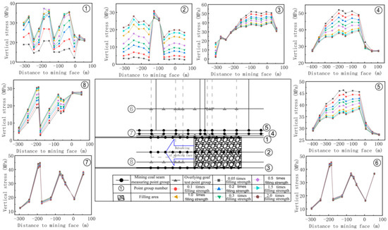
Figure A6.
Distribution of the underground pressure (300 m).
References
- Duzgun, H.S.B.; Einstein, H.H. Assessment and management of roof fall risks in underground coal mines. Saf. Sci. 2004, 42, 23–41. [Google Scholar] [CrossRef]
- Zamiran, S.; Candidate; Salam, S. Floor and Pillar Stability Considerations for Underground Disposal of Fine Coal Waste. Proceeding of the 49th Us Rock Mechanics/geomechanics Symposium, San Francisco, CA, USA, 28 June–1 July 2015. [Google Scholar]
- Zamiran, S.; Osouli, A. Subsidence and Stability Investigation of an Illinois Coal Mine. Proceeding of the 13th ISRM International Congress of Rock Mechanics, Montréal, QC, Canada, 10–13 May 2015. [Google Scholar]
- Li, M.; Zhou, N.; Zhang, J.X. Numerical modelling of mechanical behavior of coal mining hard roofs in different backfill ratios: A case study. Energies 2017, 10, 1005. [Google Scholar]
- Hang, J.; Zhou, N.; Huang, Y.L.; Zhang, Q. Impact law of the bulk ratio of backfilling body to overlying strata movement in fully mechanized backfilling mining. J. Min. Sci. 2011, 47, 73–84. [Google Scholar]
- Zhang, J.X.; Miao, X.X.; Guo, G.L. Study on waste-filling method and technology in fully mechanized coal mining. J. China Coal Soc. 2010, 35, 1–6. [Google Scholar]
- Zhou, D.; Wu, K.; Miao, X.X. Combined prediction model for mining subsidence in coal mining areas covered with thick alluvial soil layer. Bull. Eng. Geol. Environ. 2018, 77, 1–22. [Google Scholar] [CrossRef]
- Huang, J.; Tian, C.; Xing, L.; Bian, Z.; Miao, X.X. Green and sustainable mining: Underground coal mine fully mechanized solid dense stowing-mining method. Sustainability 2017, 9, 1418. [Google Scholar] [CrossRef]
- Miao, X.X.; Zhang, J.X.; Guo, G.L. Comprehensive Mechanized Solid Waste Filling Mining Method and Technology; China University of Mining and Technology Press: Xuzhou, China, 2010. [Google Scholar]
- Li, M.; Zhang, J.X.; Huang, Y.L. Effects of particle size of crushed gangue backfill materials on surface subsidence and its application under buildings. Environ. Earth Sci. 2017, 76, 603. [Google Scholar] [CrossRef]
- Zhou, N.; Zhang, J.X.; Yan, H. Deformation behavior of hard roofs in solid backfill coal mining using physical models. Energies 2017, 10, 557. [Google Scholar] [CrossRef]
- Li, M.; Zhang, J.X.; Gao, R. Compression characteristics of solid wastes as backfill materials. Adv. Mater. Sci. Eng. 2016, 2016, 2496194. [Google Scholar] [CrossRef]
- Zhang, J.X.; Zhang, Q.; Sun, Q.; Gao, R.; Germain, D. Surface subsidence control theory and application to backfill coal mining technology. Environ. Earth Sci. 2015, 74, 1439–1448. [Google Scholar] [CrossRef]
- Feng, J.; Zhang, J.X.; Huang, Y.L. Waste filling technology under condition of complicated geological condition working face. Procedia Earth Planet. Sci. 2009, 1, 1220–1227. [Google Scholar] [CrossRef]
- Zhang, J.X.; Wu, Q.; Huang, Y.L. Strata pressure behavior by raw waste backfilling with coal mining technology. J. China Coal Soc. 2010, 35, 1–4. [Google Scholar]
- Huang, Y.L.; Zhang, J.X.; Li, M.; Jiang, H. Waste substitution extraction of coal strip mining pillars. Res. J. Chem. Environ. 2013, 17, 96–103. [Google Scholar]
- Chang, Q.; Chen, J.; Zhou, H. Implementation of paste backfill mining technology in Chinese coal mines. Sci. World J. 2014. [Google Scholar] [CrossRef] [PubMed]
- Yang, J.X.; Liu, C.Y.; Yu, B.; Wu, F.F. Roof structure of close distance coal strata in multi-goaf condition and its effects. Acta Geodyn. Geomater. 2014, 11, 351–359. [Google Scholar]
- Zhu, X.; Guo, G.L.; Zha, J.F.; Chen, T.; Fang, Q. Surface dynamic subsidence prediction model of solid backfill mining. Environ. Earth Sci. 2016, 75, 1007. [Google Scholar] [CrossRef]
- Guo, Q.; Guo, G.L.; Zha, J.F.; Lv, X.; Wang, J. Research on the surface movement in a mountain mining area: A case study of Sujiagou Mountain, China. Environ. Earth Sci. 2016, 75, 1–19. [Google Scholar] [CrossRef]
- Yang, J.X. Mechanism of complex mine pressure manifestation on coal mining work faces and analysis on the instability condition of roof block. Acta Geodyn. Geomater. 2015, 1, 1–8. [Google Scholar] [CrossRef]
- Huang, Y.L.; Li, J.; Song, T.; Kong, G. Analysis on filling ratio and shield supporting pressure for overburden movement control in coal mining with compacted backfilling. Energies 2016, 10, 31. [Google Scholar] [CrossRef]
- Huang, Y.L. Theory and Application of Ground Pressure Control for Solid Dense Backfill Mining. Ph.D. Thesis, China University of Mining and Technology, Xuzhou, China, 2012. [Google Scholar]
- Zhang, J.X.; Zhang, Q.; Huang, Y.L. Strata movement controlling effect of waste and fly ash backfilling in fully mechanized coal mining with backfilling face. Int. J. Min. Sci. Technol. 2011, 21, 721–726. [Google Scholar] [CrossRef]
- Qian, M.G.; Shi, P.W.; Xu, J.L. Ground Pressure and Strata Control, 2nd ed.; China University of Mining and Technology Press: Xuzhou, China, 2003. [Google Scholar]
- Huang, Y.L.; Zhang, J.X.; Zhou, Q. Overlying strata movement law in fully mechanized coal mining and backfilling longwall face by similar physical simulation. J. Min. Sci. 2011, 47, 618–627. [Google Scholar]
- Zhu, W.; Xu, J.; Xu, J.; Chen, D. Pier-column backfill mining technology for controlling surface subsidence. Int. J. Rock Mech. Min. Sci. 2017, 96, 58–65. [Google Scholar] [CrossRef]
- Guo, Q.; Guo, G.L.; Lv, X.; Zhang, W. Strata movement and surface subsidence prediction model of dense solid backfilling mining. Environ. Earth Sci. 2016, 75, 1426. [Google Scholar] [CrossRef]
- Du, W.J. Coal Seam Gas Resources Evaluation and Mining Law in Fuxin Mining Area. Ph.D. Thesis, Liaoning Project Technology University, Fuxin, China, 2010. [Google Scholar]
- Itasca Software Company. Theory and Background, Constitutive Model: Theory and Implementation. In User Manual of FLAC3D5.0; Itasca Software Company: Minneapolis, MN, USA, 2013. [Google Scholar]
- Sun, S.W.; Lin, H.; Ren, L.W. Application of FLAC3D in Geotechnical Engineering, 1st ed.; China Waterpower Press: Beijing, China, 2011. [Google Scholar]
- Wood, D.M. Soil Behavior and Criterion State Soil Mechanics; Cambridge University Press: Cambridge, UK, 1990. [Google Scholar]
- Zheng, Y.R.; Shen, Z.J.; Gong, X.N. The Principle of Rock and Soil Plastic Mechanics; China Construction Industry Press: Beijing, China, 2002. [Google Scholar]
- Borák, L.; Marcián, P. Beams on elastic foundation using modified betti’s theorem. Int. J. Mech. Sci. 2014, 88, 17–24. [Google Scholar] [CrossRef]
- Huang, Y.; He, F.S. A Beam, Plate, and Shell on an Elastic Foundation; The Science Publishing Company: Beijing, China, 2005. [Google Scholar]
- Cao, X.; Zhang, H.X. Refined theory of transversely isotropic elastic beam posting inside winklers foundation. Appl. Mech. Mater. 2013, 405, 3218–3221. [Google Scholar] [CrossRef]
- Kovářová, J.; Schlegel, M.; Dupal, J. Vibration control of cantilever beam. J. Vibroeng. 2007, 9, 45–48. [Google Scholar]
- Zhang, B.S.; Wang, M.Z.; Yu, X. Refined theory of beam on Winkler foundation. Chin. J. Appl. Mech. 2005, 4. [Google Scholar]
- Yao, X.L.; Whittaker, B.N.; Reddish, D.J. Influence of overburden mass behavioral properties on subsidence limit characteristics. Min. Sci. Technol. 1991, 13, 167–173. [Google Scholar] [CrossRef]
- Mainil, P. Contribution to the study of ground movements under the influence of mining operations. Int. J. Rock Mech. Min. Sci. Geomech. Abstr. 1965, 2, 225, IN15, 228–229, IN16, 243. [Google Scholar] [CrossRef]
- Singh, K.B.; Singh, T.N. Ground movements over longwall workings in the Kamptee coalfield, India. Eng. Geol. 1998, 50, 125–139. [Google Scholar] [CrossRef]
- Xie, J.; Zhu, W.; Xu, J.L.; Wen, J. A study on the bearing effect of pier column backfilling in the goaf of a thin coal seam. Geosci. J. 2016, 20, 361–369. [Google Scholar] [CrossRef]
© 2018 by the authors. Licensee MDPI, Basel, Switzerland. This article is an open access article distributed under the terms and conditions of the Creative Commons Attribution (CC BY) license (http://creativecommons.org/licenses/by/4.0/).