New Trends in the Application of Carbon-Bearing Materials in Blast Furnace Iron-Making


Abstract
1. Introduction
- The review starts by a brief description of the existing technologies of iron-making, including BF and alternative technologies.
- Conventional reducing agents (mainly coke) including production, its role in the BF iron-making and the most important required properties.
- Description of materials that have reduction potential (for example; carbon rich in-plant fines, waste plastic, and bio-based carbon materials)
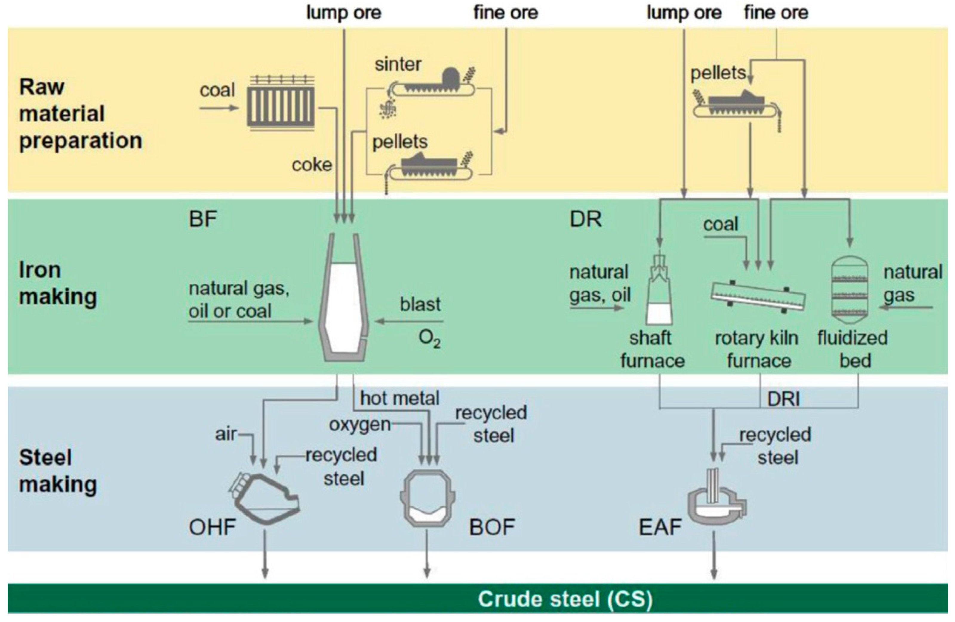
2. The Making of Iron: An Overview
2.1. Raw Materials
2.1.1. Iron Ores
2.1.2. Carbon-Bearing Material
2.1.3. Fluxes
2.1.4. Reverts
2.2. Methods of Iron and Steel-making
- The BF and the basic oxygen furnace (BOF) route; in this route coke and coal are the main carbon sources. Through this route approximately 70% of the world steel is being produced.
- Recycling of scrap through melting in electric arc furnace (EAF); through this route about 25% of the world steel is produced. Therefore, this route is considered the second important route for steel production.
- The direct reduction (DR) followed by smelting in EAF; by this route ~5% of the world steel is being produced and the most common used carbonaceous material in this case is natural gas.
- The smelting reduction followed by BOF; through this route only ~0.4% of the world steel is being produced. In this route neither ore preparation nor coking are needed.
3. Conventional Carbon-Bearing Materials
- Mechanical role: low reactive and strong coke descending along with the burden materials ensures good gas permeability and distribution, percolation of liquid iron and adsorption of dust. Moreover, left unreacted coke provides mechanical support for the descending materials.
- Source of carbon: coke along with other carbonaceous materials in the BF are responsible for producing reducing substances and hot metal carburization.
- Energy supplier: the combustion of carbonaceous materials including coke by hot blast in front of the tuyeres provides the majority of heat required in the BF.
4. Alternative Carbon-Bearing Materials
- Low contents of sulfur, phosphorus, and alkali: sulfur and phosphorus removal in later process stages increases costs. Higher alkali content results in alkali accumulation and circulation in the furnace which not only attacks the refractory lining but also results in energy losses.
- Moisture content: moisture content should be kept minimum
- Volatile content: the volatile content in the carbon source should be controlled as it affects the gasification process in the raceway. Higher volatiles mean less replacement ratio for coke as well as low heating value.
- Controlled hardness or grindability
- High solid or fixed carbon content, low ash, and high heating value.
4.1. Active (Nut) Coke
4.2. In-Plant Fines
4.3. Bio-Based Carbon-Bearing Materials
4.4. Waste Plastic Materials
4.5. Carbon Composite Agglomerates
- Improved reaction kinetics;
- Possibility of using iron and/or carbon rich in-plant fines [59];
- Less dependency on CO2 and energy intensive ore preparation processes.
5. Trends in the Applications of Alternative Carbon-Bearing Materials
5.1. Sintering
5.2. Coking Coal
- Reactivity (coke reactivity index, CRI) and strength (coke strength after reaction, CSR) are the most important measures that are considered for evaluating coke properties. Good quality coke is always characterized by relatively low CRI (<30) and relatively high CSR (>55) [73]. Adding charcoal to the coal blend increases the reactivity of the produced bio-coke which is attributed to the calcium and/or alkali content of the charcoal, the higher the alkali index the higher the reactivity [70]. On the other hand, the poor mechanical properties, like strength and low density, have negative impacts on the mechanical properties of the produced bio-coke [74].
5.4. BF Iron-Making
5.4.1. Top Charging
Nut Coke
In-Plant Fines
Biomass
Plastic Materials
5.4.2. Injection
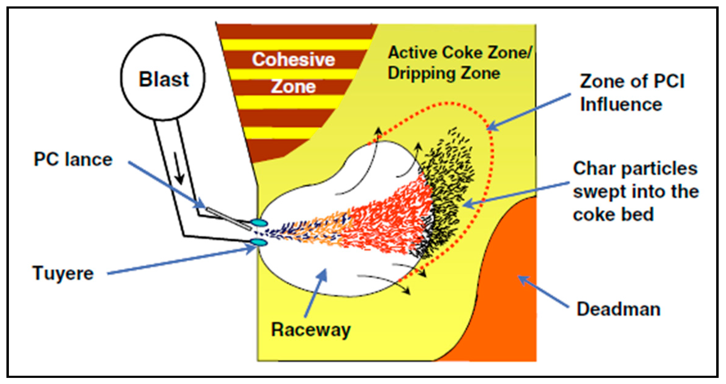
Pulverized Coal Injection (PCI)
Injection of Oil and Natural Gas
In-Plant Gases
Waste Plastics Injection
In-Plant Fines
Biomass Injection
6. Conclusions
- Efficient utilization of active under size coke and in-plant gases and fines instead of the virgin metallurgical coke results in lowering the overall energy and carbon consumption and consequently decreases the CO2 emission.
- Replacing the coke with renewable, neutral and H2 rich carbon-bearing materials will directly reduce the CO2 emission due to the increased share of H2 as a reducing agent. These materials can be introduced to the iron-making processes via several means:
- (a)
- Partial replacement of coke breeze in the sintering process;
- (b)
- Blending with coking coal prior to the coke-making process;
- (c)
- Partial replacement of top charged coke by lump charcoal; and
- (d)
- Replacement of injectant pulverized coal with waste plastics, charcoal, or torrefied biomass.
- Producing agglomerates from secondary resources and/or alternative carbonaceous materials provides an opportunity to utilize wide range of materials, including mechanically unsuitable materials for direct use.
- Utilization of highly reactive carbon and/or carbon composite agglomerates will shift the iron oxide reduction process toward lower carbon consumption.
Funding
Acknowledgments
Conflicts of Interest
References
- World Steel Association. Steel’s Contribution to a Low Carbon Future: Worldsteel Position Paper; World Steel Association: Brussels, Belgium, 2010. [Google Scholar]
- Brown, T.; Gambhir, A.; Florin, N.; Fennell, P. Reducing CO2 Emissions from Heavy Industry: A Review of Technologies and Considerations for Policy Makers; Briefing paper No7; Imperial College: London, UK, 2012. [Google Scholar]
- Coal & Steel Statistics 2014. Available online: https://www.worldcoal.org/sites/default/files/resources_files/coal_steel_facts_2014%2812_09_2014%29.pdf (accessed on 3 April 2018).
- Pardo, N.; Moya, J.A. Prospective scenarios on energy efficiency and CO2 emissions in the European Iron & Steel industry. Energy 2013, 54, 113–128. [Google Scholar]
- Protocol, K. United Nations Framework Convention on Climate Change; Kyoto Protocol; United Nations: New York, NY, USA, 1997; Volume 19. [Google Scholar]
- Babich, A.; Senk, D. Coal Use in Iron and Steel Metallurgy. In The Coal Handbook: Towards Cleaner Production; Osborne, D., Ed.; Coal Utilisation; Elsevier: York, NY, USA, 2013; Volume 2. [Google Scholar]
- Schmöle, P.; Lüngen, H. In Hot metal production in the blast furnace gas from an ecological point of view. In Proceedings of the 2nd International Meeting on Ironmaking and 1st International Symposium on Iron Ore, Vitoria, Brazil, 12–15 September 2004. [Google Scholar]
- Babich, A.; Senk, D.; Yaroshevskiy, S.; Chlaponin, N.S.; Kochura, V.; Kuzin, A.; Бабич, А.; Кoчура, В.; Ярoшевский, С.; Кузин, А. In Effect of nut coke on blast furnace shaft permeability. In Proceedings of the 3rd International Conference on Process Development in Iron and Steelmaking (SCANMET III), Lulea, Sweden, 8–11 June 2008; Volume 2, pp. 227–236. [Google Scholar]
- Nomura, S.; Higuchi, K.; Kunitomo, K.; Naito, M. Reaction behavior of Formed Iron Coke and Its Effect on Decreasing Thermal Reserve Zone Temperature in Blast Furnace. ISIJ Int. 2010, 50, 1388–1395. [Google Scholar] [CrossRef]
- Nomura, S.; Ayukawa, H.; Kitaguchi, H.; Tahara, T.; Matsuzaki, S.; Naito, M.; Koizumi, S.; Ogata, Y.; Nakayama, T.; Abe, T. Improvement in Blast Furnace Reaction Efficiency through the Use of Highly Reactive Calcium Rich Coke. ISIJ Int. 2005, 45, 316–324. [Google Scholar] [CrossRef]
- Nomura, S.; Kitaguchi, H.; Yamaguchi, K.; Naito, M. The characteristics of catalyst-coated highly reactive coke. ISIJ Int. 2007, 47, 245–253. [Google Scholar] [CrossRef]
- Nomura, S.; Terashima, H.; Sato, E.; Naito, M. Some fundamental aspects of highly reactive iron coke production. Tetsu-to-Hagane (J. Iron Steel Inst. Jpn.) 2006, 92, 849–856. [Google Scholar] [CrossRef]
- Kasai, A.; Matsui, Y. Lowering of thermal reserve zone temperature in blast furnace by adjoining carbonaceous material and iron ore. ISIJ Int. 2004, 44, 2073–2078. [Google Scholar] [CrossRef]
- Kasai, A.; Toyota, H.; Nozawa, K.; Kitayama, S. Reduction of reducing agent rate in blast furnace operation by carbon composite iron ore hot briquette. ISIJ Int. 2011, 51, 1333–1335. [Google Scholar] [CrossRef]
- Ueda, S.; Yanagiya, K.; Watanabe, K.; Murakami, T.; Inoue, R.; Ariyama, T. Reaction model and reduction behavior of carbon iron ore composite in blast furnace. ISIJ Int. 2009, 49, 827–836. [Google Scholar] [CrossRef]
- Ahmed, H.M.; Viswanathan, N.; Bjorkman, B. Composite Pellets—A Potential Raw Material for Iron-Making. Steel Res. Int. 2014, 85, 293–306. [Google Scholar] [CrossRef]
- Naito, M.; Okamoto, A.; Yamaguchi, K.; Yamaguchi, T.; Inoue, Y. Improvement of Blast Furnace Reaction Efficiency by Temperature Control of Thermal Reserve Zone; Nippon Steel: Tokyo, Japan, 2006. [Google Scholar]
- Hanrot, F.; Sert, D.; Delinchant, J.; Pietruck, R.; Bürgler, T.; Babich, A.; Fernández López, M.; Álvarez García, R.; Díez Díaz-Estébanez, M. CO2 mitigation for steelmaking using charcoal and plastics wastes as reducing agents and secondary raw materials. In Proceedings of the 1st Spanish National Conference on Advances in Materials Recycling and Eco-Energy, Madrid, Spain, 12–13 November 2009. [Google Scholar]
- Seetharaman, S. Industrial processes. In Treatise on Process Metallurgy; Elsevier: York, NY, USA, 2013; Volume 3. [Google Scholar]
- Biswas, A.K. Principles of Blast Furnace Ironmaking: Theory and Practice; Cootha: Brisbane, Australia, 1981. [Google Scholar]
- Geerdes, M.; Chaigneau, R.; Kurunov, I. Modern Blast Furnace Ironmaking: An Introduction (2015); Ios Press: Amsterdam, The Netherlands, 2015. [Google Scholar]
- Peacey, J.G.; Davenport, W.G. The Iron Blast Furnace: Theory and Practice; International Series on Materials Science and Technology; Pergamon Press: Oxford, UK, 1979; Volume 31, p. 251. [Google Scholar]
- World Steel Association. The World Steel Association Energy Fact Sheet 2008. Available online: https://www.worldsteel.org/?action=programs&id=68&about=1 (accessed on 23 March 2017).
- World Steel in Figures 2015. Available online: https://www.worldsteel.org (accessed on 23 March 2017).
- Nomura, S. Recent developments in cokemaking technologies in Japan. Fuel Process. Technol. 2017, 159, 1–8. [Google Scholar] [CrossRef]
- Luengen, H.B.; Peters, M.; Schmoele, P. Ironmaking in Western Europe. Iron Steel Technol. 2012, 9, 63–69. [Google Scholar]
- Carpenter, A.M. Use of PCI in Blast Furnaces; IEA Clean Coal Centre: London, UK, 2006. [Google Scholar]
- Sahajwalla, V.; Gupta, S. TRP0033-PCI Coal Combustion Behavior and Residual Coal Char Carryover in the Blast Furnace of 3 American Steel Companies during Pulverized Coal Injection (PCI) at High Rates; School of Materials Science and Engineering, University of New South Wales: Sydney, Australia, 2005. [Google Scholar]
- Carpenter, A.M. Injection of Coal and Waste Plastics in Blast Furnaces; IEA Clean Coal Centre: London, UK, 2010. [Google Scholar]
- Chukwuleke, O.P.; Cai, J.J.; Chukwujekwu, S.; Xiao, S. Shift from Coke to Coal Using Direct Reduction Method and Challenges. J. Iron Steel Res. Int. 2009, 16, 1–5. [Google Scholar] [CrossRef]
- Guangqing, Z.; Oleg, O. Energy and Exergy Analyses of Low Coke Blast Furnace Ironmaking. In Proceedings of the 5th International Congress on the Science and Technology of Ironmaking, Shanghai, China, 20–22 October 2009; pp. 603–607. [Google Scholar]
- Lacroix, P.; Dauwels, G.; Dufresne, P.; Godijn, R.; Perini, P.; Stricker, K.; Virtala, J. High blast furnaces productivity operations with low coke rates in the European Union. Revue de Métallurgie 2001, 98, 259–268. [Google Scholar] [CrossRef]
- Podkorytov, A.; Kuznetsov, A.; Dymchenko, E.; Padalka, V.; Yaroshevskii, S.; Kuzin, A. Theoretical and experimental foundations for preparing coke for blast-furnace smelting. Metallurgist 2009, 53, 322–328. [Google Scholar] [CrossRef]
- Das, B.; Prakash, S.; Reddy, P.; Misra, V. An overview of utilization of slag and sludge from steel industries. Resour. Conserv. Recycl. 2007, 50, 40–57. [Google Scholar] [CrossRef]
- Trung, Z.H.; Kukurugya, F.; Takacova, Z.; Orac, D.; Laubertova, M.; Miskufova, A.; Havlik, T. Acidic leaching both of zinc and iron from basic oxygen furnace sludge. J. Hazard. Mater. 2011, 192, 1100–1107. [Google Scholar] [CrossRef] [PubMed]
- Steer, J.M.; Griffiths, A.J. Investigation of carboxylic acids and non-aqueous solvents for the selective leaching of zinc from blast furnace dust slurry. Hydrometallurgy 2013, 140, 34–41. [Google Scholar] [CrossRef]
- Vereš, J.; Lovás, M.; Jakabský, Š.; Šepelák, V.; Hredzák, S. Characterization of blast furnace sludge and removal of zinc by microwave assisted extraction. Hydrometallurgy 2012, 129, 67–73. [Google Scholar] [CrossRef]
- Grip, C. Steel and sustainability: Scandinavian perspective. Ironmak. Steelmak. 2005, 32, 235–241. [Google Scholar] [CrossRef]
- Butterworth, P.; Linsley, K.; Aumonier, J. Hydrocyclone treatment of blast furnace slurry within British Steel. Revue de Metallurgie Cahiers d’Informations Techniques 1996, 93, 807–815. [Google Scholar] [CrossRef]
- Heijwegen, C.; Kat, W. Beneficiation of Blast Furnace Sludge. World Steel Metalwork Export Man 1984, 26, 35–39. [Google Scholar]
- Itoh, Y.; Fieser, A. Zinc Removal from Blast Furnace Dust. Iron Steel Eng. 1982, 59, 33–36. [Google Scholar]
- Van Herck, P.; Vandecasteele, C.; Swennen, R.; Mortier, R. Zinc and lead removal from blast furnace sludge with a hydrometallurgical process. Environ. Sci. Technol. 2000, 34, 3802–3808. [Google Scholar] [CrossRef]
- Robinson, R. High temperature properties of by-product cold bonded pellets containing blast furnace flue dust. Thermochim. Acta 2005, 432, 112–123. [Google Scholar] [CrossRef]
- Su, F.; Lampinen, H.; Robinson, R. Recycling of sludge and dust to the BOF converter by cold bonded pelletizing. ISIJ Int. 2004, 44, 770–776. [Google Scholar] [CrossRef]
- Assis, S.P.; Calixto, O.K.; Vasques, F.I.; Prado, T.M.; Martins, E.M. Economical Feasibility of the Use of Biogas in Iron- and Steelmaking. In Proceedings of the Iron and Steel Technology Conference and Exposition, Cleveland, OH, USA, 4–7 May 2015; pp. 652–655. [Google Scholar]
- Matsumura, T.; Ichida, M.; Nagasaka, T.; Kato, K. Carbonization behaviour of woody biomass and resulting metallurgical coke properties. ISIJ Int. 2008, 48, 572–577. [Google Scholar] [CrossRef]
- Janiana, M.; Eduardo, O.; Antonio, V.; Alexander, B.; Heinrich, G.; Dieter, S. Study of the Behavior of Biomass, Coal and Mixtures at Their Injection into Blast Furnace. In Proceedings of the 5th International Congress on the Science and Technology of Ironmaking, Shanghai, China, 20–22 October 2009; pp. 804–808. [Google Scholar]
- Ueda, S.; Watanabe, K.; Yanagiya, K.; Inoue, R.; Ariyama, T. Improvement of Reactivity of Carbon Iron Ore Composite with Biomass Char for Blast Furnace. ISIJ Int. 2009, 49, 1505–1512. [Google Scholar] [CrossRef]
- Hata, Y.; Purwanto, H.; Hosokai, S.; Hayashi, J.; Kashiwaya, Y.; Akiyama, T. Biotar Ironmaking Using Wooden Biomass and Nanoporous Iron Ore. Energy Fuels 2009, 23, 1128–1131. [Google Scholar] [CrossRef]
- Fan, X.; Ji, Z.; Gan, M.; Chen, X.; Yin, L.; Jiang, T. Characteristics of prepared coke–biochar composite and its influence on reduction of NOx emission in iron ore sintering. ISIJ Int. 2015, 55, 521–527. [Google Scholar] [CrossRef]
- Feliciano-Bruzual, C. Charcoal injection in blast furnaces (Bio-PCI): CO2 reduction potential and economic prospects. J. Mater. Res. Technol. 2014, 3, 233–243. [Google Scholar] [CrossRef]
- Gan, M.; Fan, X.; Ji, Z.; Jiang, T.; Chen, X.; Yu, Z.; Li, G.; Yin, L. Application of biomass fuel in iron ore sintering: Influencing mechanism and emission reduction. Ironmak. Steelmak. 2015, 42, 27–33. [Google Scholar] [CrossRef]
- Babich, A.; Senk, D. Recent developments in blast furnace iron-making technology. In Iron Ore: Mineralogy, Processing and Environmental Sustainability; Lu, L., Ed.; Elsevier: York, NY, USA, 2015. [Google Scholar]
- The Statistics Portal. Available online: http://www.statista.com/statistics/282732/global-production-of-plastics-since-1950 (accessed on 23 March 2017).
- Sahajwalla, V.; Rahman, M.; Khanna, R.; Saha-Chaudhury, N.; O’Kane, P.; Skidmore, C.; Knights, D. Recycling Waste Plastics in EAF Steelmaking: Carbon/Slag Interactions of HDPE-Coke Blends. Steel Res. Int. 2009, 80, 535–543. [Google Scholar]
- Babich, A.; Senk, D.; Knepper, M.; Benkert, S. Conversion of injected waste plastics in blast furnace. Ironmak. Steelmak. 2016, 43, 11–21. [Google Scholar] [CrossRef]
- Dutta, S.K.; Ghosh, A. Study of nonisothermal reduction of iron ore-coal/char composite pellet. MMTB 1994, 25, 15–26. [Google Scholar] [CrossRef]
- Chu, M.; Nogami, H.; Yagi, J. Numerical Analysis on Charging Carbon Composite Agglomerates into Blast Furnace. ISIJ Int. 2004, 44, 510–517. [Google Scholar] [CrossRef]
- Chowdhury, G.M.; Roy, G.G.; Roy, S.K. Reduction Kinetics of Iron Ore-Graphite Composite Pellets in a Packed-Bed Reactor under Inert and Reactive Atmospheres. Metall. Mater. Trans. B 2008, 39, 160–178. [Google Scholar] [CrossRef]
- Bhagat, R.P.; Chattoraj, U.S.; Sil, S.K. Porosity of Sinter and its relation with the sintering indices. ISIJ Int. 2006, 46, 1728–1730. [Google Scholar] [CrossRef]
- Kokubu, H.; Kodama, T.; Itaya, H.; Oguchi, Y. Formation of pores in iron ore sinter. Trans. Iron Steel Inst. Jpn. 1986, 26, 182–185. [Google Scholar] [CrossRef]
- Fan, X.; Ji, Z.; Gan, M.; Chen, X.; Li, Q.; Jiang, T. Influence of preformation process on combustibility of biochar and its application in iron ore sintering. ISIJ Int. 2015, 55, 2342–2349. [Google Scholar] [CrossRef]
- Lovel, R.R.; Vining, K.R.; Dell’Amico, M. The influence of fuel reactivity on iron ore sintering. ISIJ Int. 2009, 49, 195–202. [Google Scholar] [CrossRef]
- Lu, L. Iron Ore: Mineralogy, Processing and Environmental Sustainability; Elsevier: York, NY, USA, 2015. [Google Scholar]
- Lu, L.; Adam, M.; Kilburn, M.; Hapugoda, S.; Somerville, M.; Jahanshahi, S.; Mathieson, J.G. Substitution of charcoal for coke breeze in iron ore sintering. ISIJ Int. 2013, 53, 1607–1616. [Google Scholar] [CrossRef]
- Mathieson, J.; Norgate, T.; Jahanshahi, S.; Somerville, M.; Haque, N.; Deev, A.; Ridgeway, P.; Zulli, P. The potential for charcoal to reduce net greenhouse gas emissions from the Australian steel industry. In Proceedings of the 6th International Congress on the Science & Technology of Ironmaking—ICSTI 2012, Rio de Janeiro, Brazil, 14–18 October 2012; Volume 3, pp. 1602–1613. [Google Scholar]
- Mousa, E.; Babich, A.; Senk, D. Iron Ore Sintering Process with Biomass Utilization. In Proceedings of the METEC & 2nd ESTAT, Düsseldorf, Gemany, 15–19 June 2015. [Google Scholar]
- Kawaguchi, T.; Hara, M. Utilization of biomass for iron ore sintering. ISIJ Int. 2013, 53, 1599–1606. [Google Scholar] [CrossRef]
- Suopajärvi, H.; Kemppainen, A.; Haapakangas, J.; Fabritius, T. Extensive review of the opportunities to use biomass-based fuels in iron and steelmaking processes. J. Clean. Prod. 2017, 148, 709–734. [Google Scholar] [CrossRef]
- MacPhee, J.; Gransden, J.; Giroux, L.; Price, J. Possible CO2 mitigation via addition of charcoal to coking coal blends. Fuel Process. Technol. 2009, 90, 16–20. [Google Scholar] [CrossRef]
- Castro Díaz, M.; Zhao, H.; Kokonya, S.; Dufour, A.; Snape, C.E. The effect of biomass on fluidity development in coking blends using high-temperature SAOS rheometry. Energy Fuels 2012, 26, 1767–1775. [Google Scholar] [CrossRef]
- Montiano, M.; Barriocanal, C.; Alvarez, R. Effect of the addition of waste sawdust on thermoplastic properties of a coal. Fuel 2013, 106, 537–543. [Google Scholar] [CrossRef]
- Alvarez, R.; Diez, M.; Barriocanal, C.; Diaz-Faes, E.; Cimadevilla, J. An approach to blast furnace coke quality prediction. Fuel 2007, 86, 2159–2166. [Google Scholar] [CrossRef]
- Montiano, M.; Díaz-Faes, E.; Barriocanal, C.; Alvarez, R. Influence of biomass on metallurgical coke quality. Fuel 2014, 116, 175–182. [Google Scholar] [CrossRef]
- Montiano, M.; Díaz-Faes, E.; Barriocanal, C. Effect of briquette composition and size on the quality of the resulting coke. Fuel Process. Technol. 2016, 148, 155–162. [Google Scholar] [CrossRef]
- Mousa, E.A.; Babich, A.; Senk, D. Effect of nut coke-sinter mixture on the blast furnace performance. ISIJ Int. 2011, 51, 350–358. [Google Scholar] [CrossRef]
- Mousa, E.; Senk, D.; Babich, A.; Gudenau, H. Influence of nut coke on iron ore sinter reducibility under simulated blast furnace conditions. Ironmak. Steelmak. 2010, 37, 219–228. [Google Scholar] [CrossRef]
- Mousa, E. Reduction of Iron Ore Burden Materials Mixed with Nut Coke Under Simulated Blast Furnace Conditions. Ph.D. Thesis, Shaker Verlag Gmbh, Aachen, Germany, 2010. [Google Scholar]
- Mousa, E.; Senk, D.; Babich, A. Reduction of Pellets-Nut Coke Mixture under Simulating Blast Furnace Conditions. Steel Res. Int. 2010, 81, 706–715. [Google Scholar] [CrossRef]
- Babich, A.; Senk, D.; Gudenau, H.W. Effect of coke reactivity and nut coke on blast furnace operation. Ironmak. Steelmak. 2009, 36, 222–229. [Google Scholar] [CrossRef]
- Nikitin, L.; Mar’yasov, M.; Gorbachev, V.; Bugaev, S.; Denisov, Y.M. Blast-furnace operation with coke fines. Metallurgist 1999, 43, 30–33. [Google Scholar] [CrossRef]
- Loginov, V.; Solomatin, S.; Korzh, A. Experimental melts with blast furnaces charged with mixture of coke and sinter. Metallurgist 1976, 20, 245–250. [Google Scholar] [CrossRef]
- Loginov, V.; Berin, A.; Solomatin, S. Effect of mixing burden with coke on blast furnace fluid mechanics and operation parameters. STAL 1977, 5, 391. [Google Scholar]
- Yaroshevskii, S.; Nozdrachev, V.; Chebotarev, A.; Rudenko, V.; Feshchenko, S.; Kuznetsov, A.; Padalka, V.; Khlaponin, N.; Kuzin, A. Efficiency of using coke fractions smaller than 40 mm in a blast furnace. Metallurgist 2000, 44, 598–605. [Google Scholar] [CrossRef]
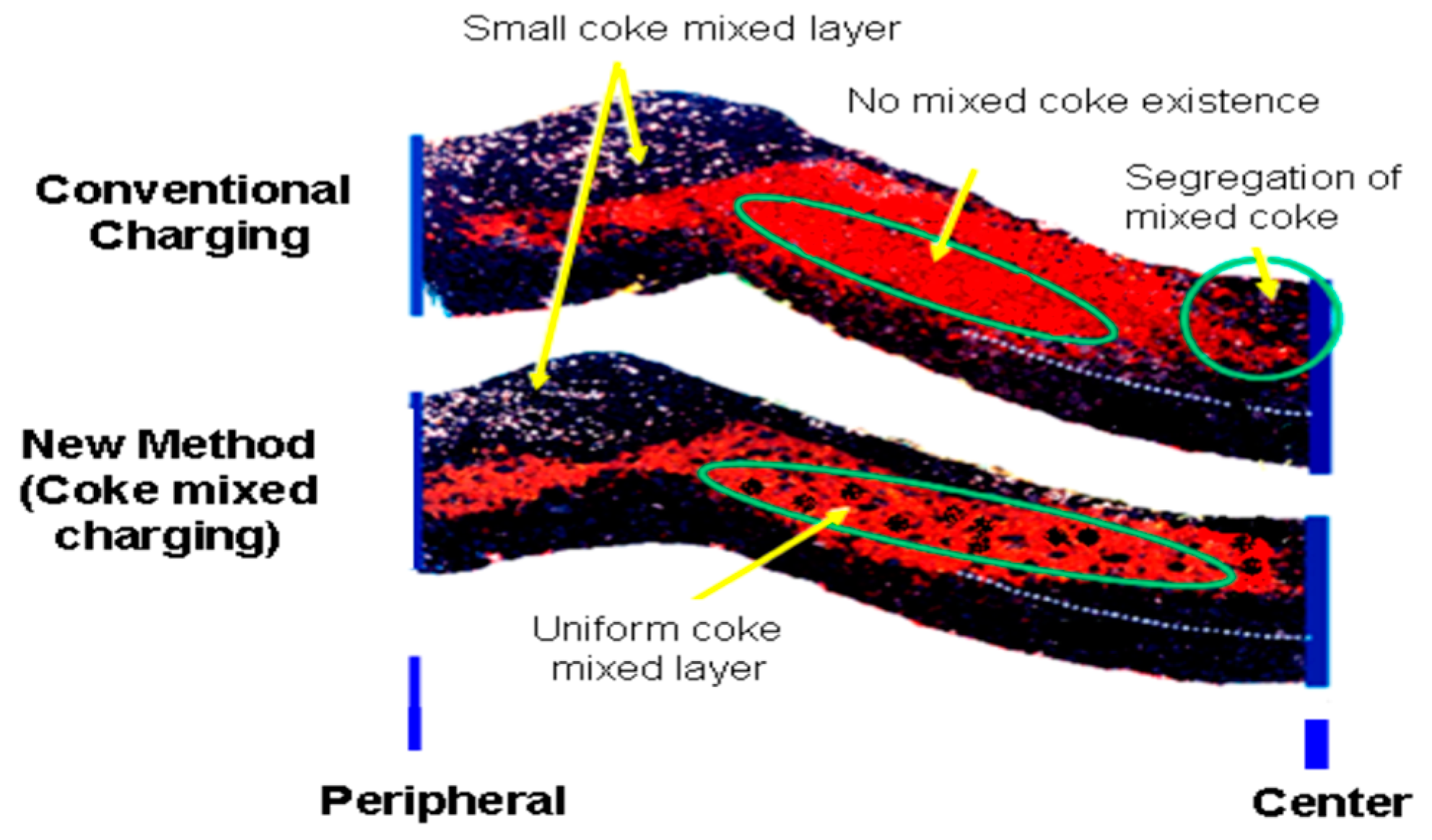
- Watakabe, S.; Takeda, K.; Nishimura, H.; Goto, S.; Nishimura, N.; Uchida, T.; Kiguchi, M. Development of high ratio coke mixed charging technique to the blast furnace. ISIJ Int. 2006, 46, 513–522. [Google Scholar] [CrossRef]
- Sawayama, M.; Miyagawa, K.; Nozawa, K.; Matsui, Y.; Shibata, K. Low coke rate operation of blast furnace by controlling size of coke mixed into ore layer. In Proceedings of the 5th International Congress on the Science and Technology of Ironmaking, Shanghai, China, 20–22 October 2009. [Google Scholar]
- Ökvist, L.S.; Brandell, C.; Lundgren, M.; AB, L. Impact of Activated nut Coke on Energy Efficiency in the Blast Furnace. Available online: https://www.lkab.com/sv/SysSiteAssets/documents/kund/2014-impact-of-activated-nut-coke-on-energy-efficiency-in-the-blast-furnace.pdf (accessed on 3 April 2018).
- Ahmed, H.; Persson, A.; Sundqvist, L.; Biorkman, B. Energy Efficient Recycling of in-Plant Fines. Energy 2014, 1, 9689. [Google Scholar] [CrossRef]
- Ahmed, H.M.; Persson, A.; Okvist, L.S.; Bjorkman, B. Reduction Behaviour of Self-reducing Blends of In-plant Fines in Inert Atmosphere. ISIJ Int. 2015, 55, 2082–2089. [Google Scholar] [CrossRef]
- Ueda, S.; Watanabe, K.; Yanagiya, K.; Inoue, R.; Ariyama, T. Optimization of Biomass Utilization for Reduction CO2 in Ironmaking Process. In Proceedings of the 5th International Congress on the Science and Technology of Ironmaking, Shanghai, China, 20–22 October 2009; pp. 593–599. [Google Scholar]
- Mirabile, D.; Pistelli, M.I.; Marchesini, M.; Falciani, R.; Chiappelli, L. Thermal valorisation of automobile shredder residue: Injection in blast furnace. Waste Manag. 2002, 22, 841–851. [Google Scholar] [CrossRef]
- Bennett, P.; Fukushima, T. Impact of PCI coal quality on blast furnace operations. In Proceedings of the 12th International Conference on Computational Science (ICCS), Melbourne, Australia and St. Petersburg, Russia, 2–4 June 2003. [Google Scholar]
- Schott, R. State-of-the-Art PCI technology for blast furnace ensured by continuous technological and economical improvement. Iron Steel Technol. 2013, 10, 63–75. [Google Scholar]
- Raask, E. Mineral Impurities in coal Combustion: Behavior, Problems, and Remedial Measures; Taylor & Francis: York, NY, USA, 1985. [Google Scholar]
- Kamijou, T.; Shimizu, M. PC Combustion in Blast Furnace. In Advanced Pulverized coal Injection Technology and Blast Furnace Operation; Pergamon: Amsterdam, The Netherlands, 2000; Volume 1, pp. 63–82. [Google Scholar]
- Mathieson, J.G.; Truelove, J.S.; Rogers, H. Toward an understanding of coal combustion in blast furnace tuyere injection. Fuel 2005, 84, 1229–1237. [Google Scholar] [CrossRef]
- Worrell, E. Energy Efficiency Improvement and Cost Saving Opportunities for the US Iron and Steel Industry—An ENERGY STAR (R) Guide for Energy and Plant Managers; Berkeley National Laboratory: Berkeley, CA, USA, 2011. [Google Scholar]
- Lingiard, O.; Burrai, O.; Partemio, C.; Giandoménico, F.; Etchevarne, P.; Gonzalez, J.M. High productivity and coke rate reduction at Siderar blast furnace# 2. In Proceedings of the 1st International Meeting on Ironmaking, Belo Horizonte, Brazil, 24 September 2001. [Google Scholar]
- Diemer, P.; Knop, K.; Luengen, H.B.; Reinke, M.; Wuppermann, C. Utilization of coke oven gas for the production of DRI. Stahl Eisen 2007, 127, 19–24. [Google Scholar]
- Spirin, N.; Shvidkiy, V.; Yaroshenko, Y.; Gordon, Y. Improvement in energy efficiency of blast furnace. In Proceedings of the METEC & ESTAD, Düsseldorf, Germany, 15–19 June 2015; pp. 15–19. [Google Scholar]
- Yang, Z.; Zhang, Y.; Wang, X.; Zhang, Y.; Lu, X.; Ding, W. Steam reforming of coke oven gas for hydrogen production over a NiO/MgO solid solution catalyst. Energy Fuels 2009, 24, 785–788. [Google Scholar] [CrossRef]
- Asanuma, M.; Ariyama, T.; Sato, M.; Murai, R.; Nonaka, T.; Okochi, I.; Tsukiji, H.; Nemoto, K. Development of waste plastics injection process in blast furnace. ISIJ Int. 2000, 40, 244–251. [Google Scholar] [CrossRef]
- Ariyama, T.; Matsuura, M.; Noda, H.; Asanuma, M.; Shikada, T.; Murai, R.; Nakamura, H.; Sumigama, T. Development of shaft-type scrap melting process characterized by massive coal and plastics injection. ISIJ Int. 1997, 37, 977–985. [Google Scholar] [CrossRef]
- Janz, J.; Weiss, W. Injection of waste plastics into the blast furnace of Stahlwerke Bremen. Revue de Métallurgie 1996, 93, 1219–1226. [Google Scholar] [CrossRef]
- Buchwalder, J.; Scheidig, K.; Schingnitz, M.; Schmöle, P. Results and trends on the injection of plastics and ASR into the blast furnace. ISIJ Int. 2006, 46, 1767–1770. [Google Scholar] [CrossRef]
- Ökvist, L.S. Co-Injection of Basic fluxes or BF Flue Dust with PC into a BF Charged with 100% Pellets: Effects on Slag Formation and Coal Combustion. Ph.D. Thesis, Luleå Tekniska Universitet, Luleå, Sweden, 2004. [Google Scholar]
- Jansson, B.; Ökvist, L.S. Injection of BF flue dust into the BF-a full-scale test at BF No. 3 in Luleå. In Proceedings of the Scanmet II 2nd International Conference on Process Development in Iron and Steelmaking, Luleå, Sweden, 6–9 June 2004; pp. 6–9. [Google Scholar]
- Wang, C.; Mellin, P.; Lövgren, J.; Nilsson, L.; Yang, W.; Salman, H.; Hultgren, A.; Larsson, M. Biomass as blast furnace injectant–Considering availability, pretreatment and deployment in the Swedish steel industry. Energy Convers. Manag. 2015, 102, 217–226. [Google Scholar] [CrossRef]
- Wang, C.; Larsson, M.; Lövgren, J.; Nilsson, L.; Mellin, P.; Yang, W.; Salman, H.; Hultgren, A. Injection of solid biomass products into the blast furnace and its potential effects on an integrated steel plant. Energy Procedia 2014, 61, 2184–2187. [Google Scholar] [CrossRef]
- Suopajärvi, H.; Pongrácz, E.; Fabritius, T. The potential of using biomass-based reducing agents in the blast furnace: A review of thermochemical conversion technologies and assessments related to sustainability. Renew. Sustain. Energy Rev. 2013, 25, 511–528. [Google Scholar] [CrossRef]


| Furnace Type | Process | Raw Material Requirement | Product | |
|---|---|---|---|---|
| Iron Ore | Reductant | |||
| Shaft furnace | BF | Sinter, pellets | Coke and coal | Molten iron |
| MIDREX | Pellets, lump | Natural gas, syn gas | Solid DRI * | |
| HyL | Pellets, lump | |||
| Fluidized bed | Finex | Fines | Coal | |
| FINMET | Natural gas | |||
| Rotary kiln | SL/RN | Lump, pellets | Coal and recycled char | |
| RHF | FASTMET | Composite pellets | coal | |
© 2018 by the author. Licensee MDPI, Basel, Switzerland. This article is an open access article distributed under the terms and conditions of the Creative Commons Attribution (CC BY) license (http://creativecommons.org/licenses/by/4.0/).
Share and Cite
Ahmed, H. New Trends in the Application of Carbon-Bearing Materials in Blast Furnace Iron-Making. Minerals 2018, 8, 561. https://doi.org/10.3390/min8120561
Ahmed H. New Trends in the Application of Carbon-Bearing Materials in Blast Furnace Iron-Making. Minerals. 2018; 8(12):561. https://doi.org/10.3390/min8120561
Chicago/Turabian StyleAhmed, Hesham. 2018. "New Trends in the Application of Carbon-Bearing Materials in Blast Furnace Iron-Making" Minerals 8, no. 12: 561. https://doi.org/10.3390/min8120561
APA StyleAhmed, H. (2018). New Trends in the Application of Carbon-Bearing Materials in Blast Furnace Iron-Making. Minerals, 8(12), 561. https://doi.org/10.3390/min8120561