Article

The Hajjar Regional Transpressive Shear Zone (Guemassa Massif, Morocco): Consequences on the Deformation of the Base-Metal Massive Sulfide Ore

1
Département des Sciences de la Terre, Faculté des Sciences, Université Moulay Ismaïl de Meknès, B.P. 11201 Zitoune Meknès, Morocco
2
Institut des Sciences de la Terre d’Orléans (ISTO), Université Orléans, CNRS BRGM UMR7327, Campus Géosciences 1A, rue de la Férollerie, 45071 Orléans, CEDEX 2, France
3
Géosciences Rennes (GR), Université de Rennes 1, CNRS UMR6118, Campus de Beaulieu, CS 74205, 35042 Rennes CEDEX, France
4
Groupe MANAGEM, Twin center, Tour A, BP 5199, Casablanca, Morocco
*
Author to whom correspondence should be addressed.
Minerals 2018, 8(10), 435; https://doi.org/10.3390/min8100435
Submission received: 30 June 2018 / Revised: 1 October 2018 / Accepted: 2 October 2018 / Published: 7 October 2018
(This article belongs to the Special Issue Structural Control of Mineral Deposits: Theory and Reality)

Abstract

:
The genesis of the base-metal massive sulfide deposits hosted within the Moroccan Hercynian Jebilet and Guemassa Massifs is still under debate. No consensus currently exists between the two models that have been proposed to explain the deposits, i.e., (1) syngenetic volcanogenic massive sulfide mineralization, and (2) synmetamorphic tectonic fluid-assisted epigenetic mineralization. Conversely, researchers agree that all Hercynian massive sulfide deposits in Morocco are deformed, even though 3D structural mapping at the deposit scale is still lacking. Therefore, while avoiding the use of a model-driven approach, the main aim of this contribution is to establish a first-order structural pattern and the controls of the Hajjar base metal deposit. We used a classical structural geology toolbox in surface and subsurface mining work to image finite strain at different levels. Our data demonstrate that: i) the Hajjar area is affected by a single foliation plane (not two) which developed during a single tectonic event encompassing a HT metamorphism. This syn-metamorphic deformation is not restricted to the Hajjar area, as it is widespread at the western Meseta scale, and it occurred during Late Carboniferous times; ii) the Hajjar ore deposit is hosted within a regional transpressive right-lateral NE-trending shear zone in which syn- to post-metamorphic ductile to brittle shear planes are responsible for significant inflexion (or virgation) of the foliation yielding an anastomosing pattern within the Hajjar shear zone. Again, this feature is not an exception, as various Late Carboniferous-Permian regional scale wrenching shear zones are recognized throughout the Hercynian Meseta orogenic segment. Finally, we present several lines of evidence emphasizing the role of deformation in terms of mechanical and fluid-assisted ore concentrations.

1. Introduction

Most Volcanogenic Massive Sulfide Deposits (VMSDs) are assumed to form within extensional and subsiding basins during both divergent and convergent plate tectonic settings (e.g., [1]). As a result, in convergent settings leading to continental collision for instance, many VMSDs underwent deformation, burial, and metamorphism. During these transformations, syngenetic massive sulfide bodies (e.g., stratoid lenses, chimneys and stockwerks) were reworked, and primary metallic bearing mineral assemblages may have been remobilized (e.g., either depleted or enriched). For this reason, the deformation and (re)mobilization of the primary sulfide concentration is a fundamental and economic matter which has been recognized and studied for a long time (e.g., [2,3,4,5,6]).
However, in spite of recent advances in modern textural (e.g., electron backscatter diffraction coupled to chemistry) and opaque mineral strain characterization (e.g., [7,8,9,10]), it still remains difficult for economic geologists dealing with deformed VMSD to decipher the respective parts of primary syngenetic vs. epigenetic mineralizing processes. As a result, metallogenic models of very large base metal concentrations all over the world are still ambiguous and under debate.
Currently, the genesis of polymetallic base-metal massive sulfide deposits (MSD) from the western Meseta domain in Morocco are currently under debate. This debate is particularly relevant for MSD from the Central Jebilet unit (Figure 1), e.g., the Kettara, Draa Sfar, Koudiat Aïcha, and Lachach deposits. Many authors consider these MSD as metamorphosed and deformed primary VMS and/or sedimentary exhalative (SEDEX) deposits [11,12,13,14,15,16,17]; however, other authors argue for a fluid-assisted syn-metamorphic origin during the major Hercynian deformation event [18,19,20,21,22]. In contrast, the Hajjar MSD located in the Hercynian Guemassa Massif (Figure 1) is considered as a metamorphosed and deformed syngenetic VMS/SEDEX deposit [12,23,24,25]. Although Hajjar shares many similar geological and mineralogical features (e.g., predominance of pyrrhotite) with the Central Jebilet MSD to the north, the hypothesis of either an epigenetic or a syn-metamorphic origin has not yet been put forward.
Since the pioneering works of Hibti (1993) [23] on the Hajjar MSD, very few studies dealing with the structural controls of this ore deposit have been carried out and published in the international literature. However, on a larger scale, much thermal and geochronological data dealing with the tectono-magmatic evolution of the western segment of the Hercynian Meseta have been published [26,27,28]. Therefore, using data collected from new outcrops, the aim of this work is to complete the Hajjar MSD structural dataset and to re-evaluate the structural context and controls; this is a prerequisite to being able to have a potential syngenetic vs. syn-metamorphic debate, if required. Our approach is to perform structural mapping at each subsurface exploitation level, yielding a 3D view of the deformation pattern. This pattern is then compared to the structural map of the surface outcrops in the Guemassa Massif.

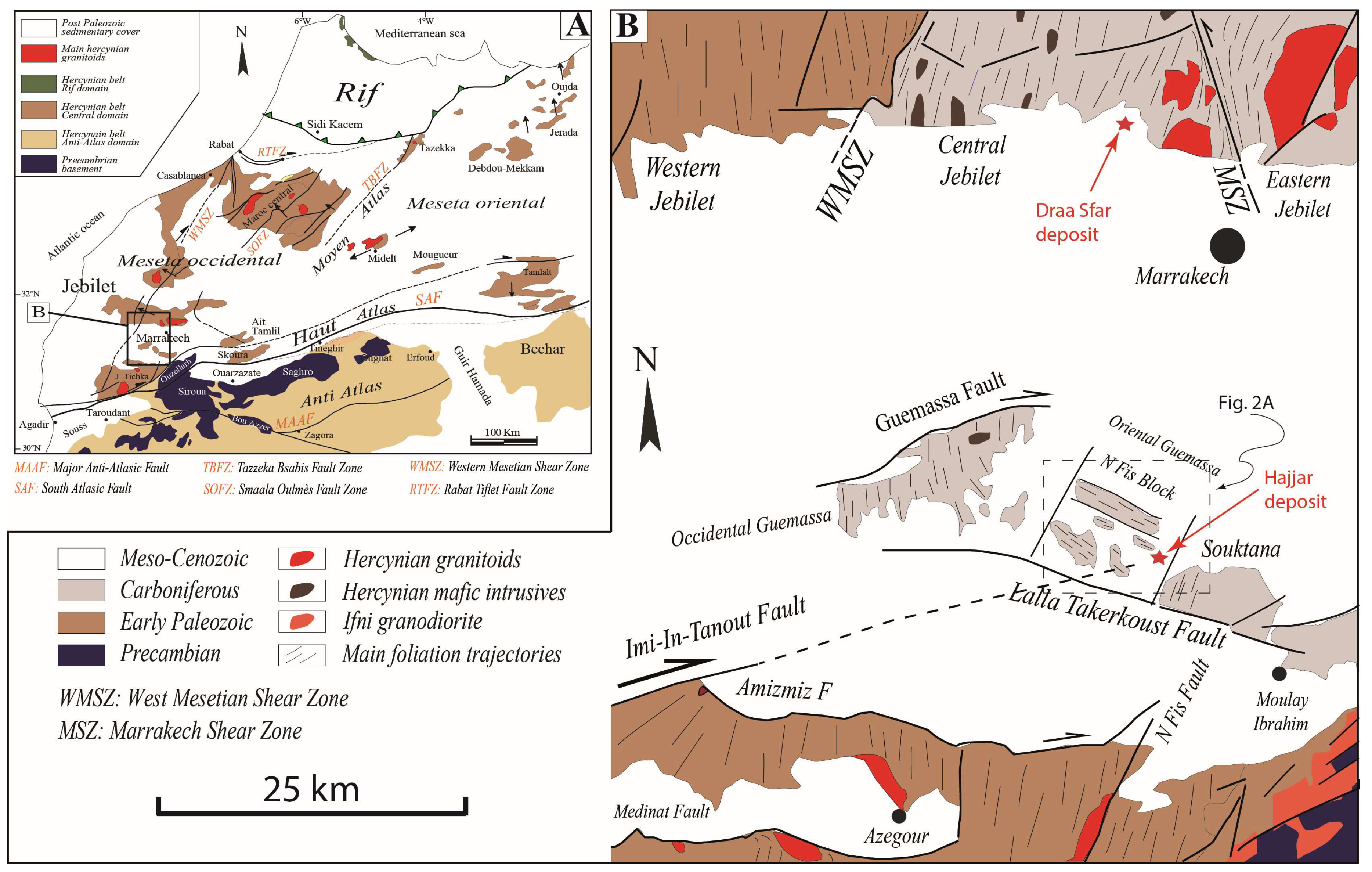
2. The Hajjar Geological and Ore Deposit Framework

The Hajjar MSD is located in the southern part of the Hercynian Occidental Meseta in Morocco, within the Guemassa Massif south of Marrakech (Figure 1). The Guemassa Massif is composed of metasediments, metavolcanites, and intrusions, all of which are Carboniferous in age (see [29,30,31]) for a detailed description of the volcano-sedimentary series). Massive sulfide lenses (and scarce magnetite bodies) are found and exploited within this volcano-sedimentary sequence [12,23] and references therein). The Hajjar mineralization corresponds to sub-lenticular bodies of various sizes containing 50–75% vol. pyrrhotite, with sphalerite, galena, chalcopyrite, pyrite, and arsenopyrite as the related major ore minerals. The tonnage is about 20 MT of ore with grades of 8% Zn, 2.3% Pb and 04–0.6% Cu [32]. The Hajjar MSD have been classified as an intermediate type between SEDEX and VMS deposits such as the Iberian Pyrite Belt giant deposits, within the “Guemassa-Jebilet” sub-type owing to its high content in pyrrhotite [25]. In the Hajjar MSD, the primary economic massive mineralization is assumed to form in a Visean basin in which an intense syn-sedimentary volcanism occurred [12,23,25]. Like the other MSD of the Occidental Meseta, the Hajjar MSD is strongly folded, faulted, and metamorphosed, which makes it difficult to recognize syngenetic/diagenetic structures and textures.
Based on the literature, the Guemassa rocks were deformed and metamorphosed during several tectonic/thermal events which affected the Guemassa Massif area [23]: i) a D0 syn-sedimentary event at the Visean-Namurian with slumps, intraformational breccias attesting to slope instabilities in the basin. These syn-sedimentary structures are encountered both within host rocks and sulfide mineralized bodies; ii) a D1 event corresponding to the incipient Hercynian deformation and responsible for a steep NW-SE foliation (S1) in the Oriental Guemassa associated with folding under regional greenschist facies metamorphic conditions. It should be noted that S1 cannot be observed clearly within the Hajjar MSD; iii) a D2 Hercynian tectono-thermal event with P2 folds and associated S2 planar cleavage oriented NE-SW under low-grade metamorphism with sericite. S2 is the predominant foliation observable in the Hajjar mine; and iv) finally, a post-kinematic thermal event, likely related to “hidden plutons”, responsible for the crystallization of static biotite porphyroblasts with cordierite and andalousite locally described at Hajjar. In this ore deposit, this thermal event has been dated using “hydrothermal” biotite at ca. 301 Ma [33]. Moreover, for Carboniferous times, the Guemassa Massif is affected by intense multiscale ductile to brittle faulting [34,35], with probable components of Atlasic reactivation during the Tertiary High Atlas orogen (the Guemassa Massif is 15 km to the north of the Atlasic thrusting front, Figure 1B). On a structural map (Figure 1B), these faults and shear zones cross-cut and delineated several blocks within the Guemassa Massif. In the Oriental Guemassa, in which the Hajjar mine is located, the N’Fis block appears to present a peculiar “anarchic” foliation orientation with respect to the bulk NNE-trend of the main Hercynian foliation in the western Meseta domain. These “anarchic” foliation orientations have been explained by deflection or virgations (here defined as a bulk inflexion of foliation plane trajectories) induced by conjugate shear zones during or shortly after a broad E-W-oriented D1 shortening [34,35]: the dominant and earlier shear zones are dextral and trend ENE–WSW (e.g., the Imi-In-Tanout Fault, the eastern branch of the Amizmiz Fault, and the Guemassa Fault, Figure 1B), whereas WNW-ESE-trending shear zones are sinistral, such as the Lalla Takerkoust Fault (Figure 1B). This “virgation model” is compatible with a W–E horizontal shortening, in contrast to Hibti’s hypothesis (1993) [23], which argued for a NE–SW horizontal shortening during the D1 event (cf. supra).
The geology of the Guemassa Massif is similar to the Central Jebilet domain (Figure 1B). Both Massifs host the major MSD of the Occidental Meseta. Thus, recent advances in the tectono-metamorphic and magmatic history of the Jebilet [26,28] may help better constrain the Guemassa Massif evolution. Based on petro-structural data, new absolute dating and thermal investigations, these authors improve the time constraints and the succession of the deformational events as follows: i) from 370 to 325 Ma (D0 of Delchini, 2018 [26]), the Jebilet area was a basin filled with syn- to post-rift sediments (the Sarhlef and Teksmin formations, respectively) intruded by shallow sills and dykes and deeper plutonic laccoliths originating from a tholeitic bimodal magmatism (e.g., the mafic/ultramafic Kettara and Sarhlef intrusions) and from a calc-alkaline magmatic suite (e.g., the Oulad-Ouaslam granodiorite) respectively; ii) from 325 to around 310 Ma, a first Hercynian event (D1) is marked by the emplacement of shallow thin skinned nappes with syn-sedimentary breccias. The internal strain is very low and no regional foliation/cleavage (S1) is reported; iii) from ca. 310 Ma to 280 Ma, the main Hercynian deformation (D2), which is polyphased and characterized by a first regional metamorphism (M2a), locally reaches the amphibolite facies (Grt-St) and a second HT/BP “contact” metamorphism in the syn-to post tectonic hornfels facies (M2b, biot + Crd + And) is associated with the leucogranite emplacement around 295 Ma. The successive foliations (S2a and S2b), sub-vertical and oriented N0/30, marked a homoaxial progressive and continual strain regime from a coaxial to a non-coaxial transpression with a broad horizontal NW-SE-trending shortening axis. Last, the D2 increments correspond to a right-lateral transpression accommodated and located along the vertical and conjugate ductile shear zones as the sinistral MSZ (Figure 1B). Therefore, the tectonic scenario proposed by Hibti (1993) [23] for the Guemassa which implies strain axis rotation between D1 and D2 and post-tectonic HT/LP metamorphism diverges from the one proposed by Delchini (2018) [26] for the Jebilet domain.

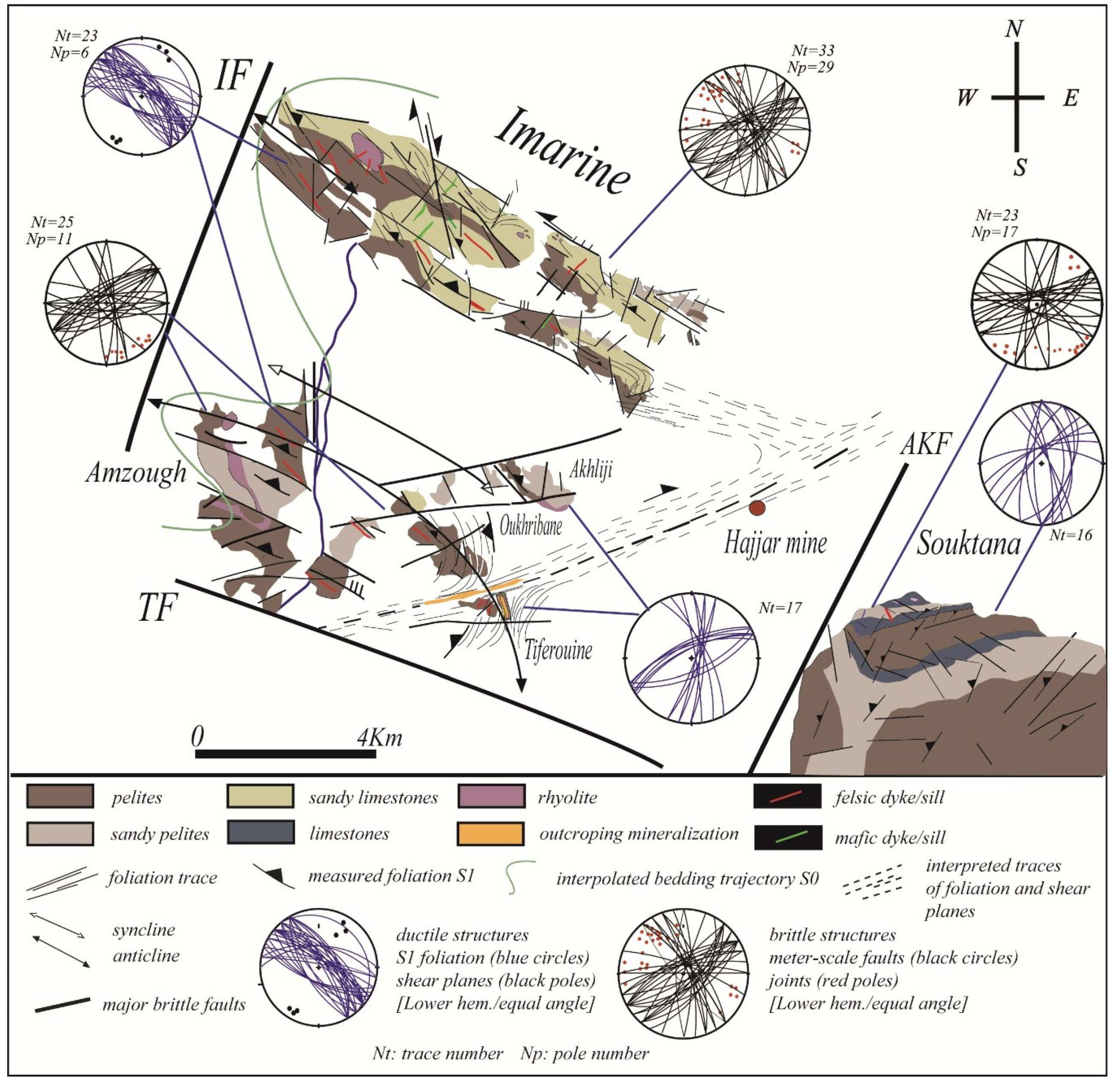
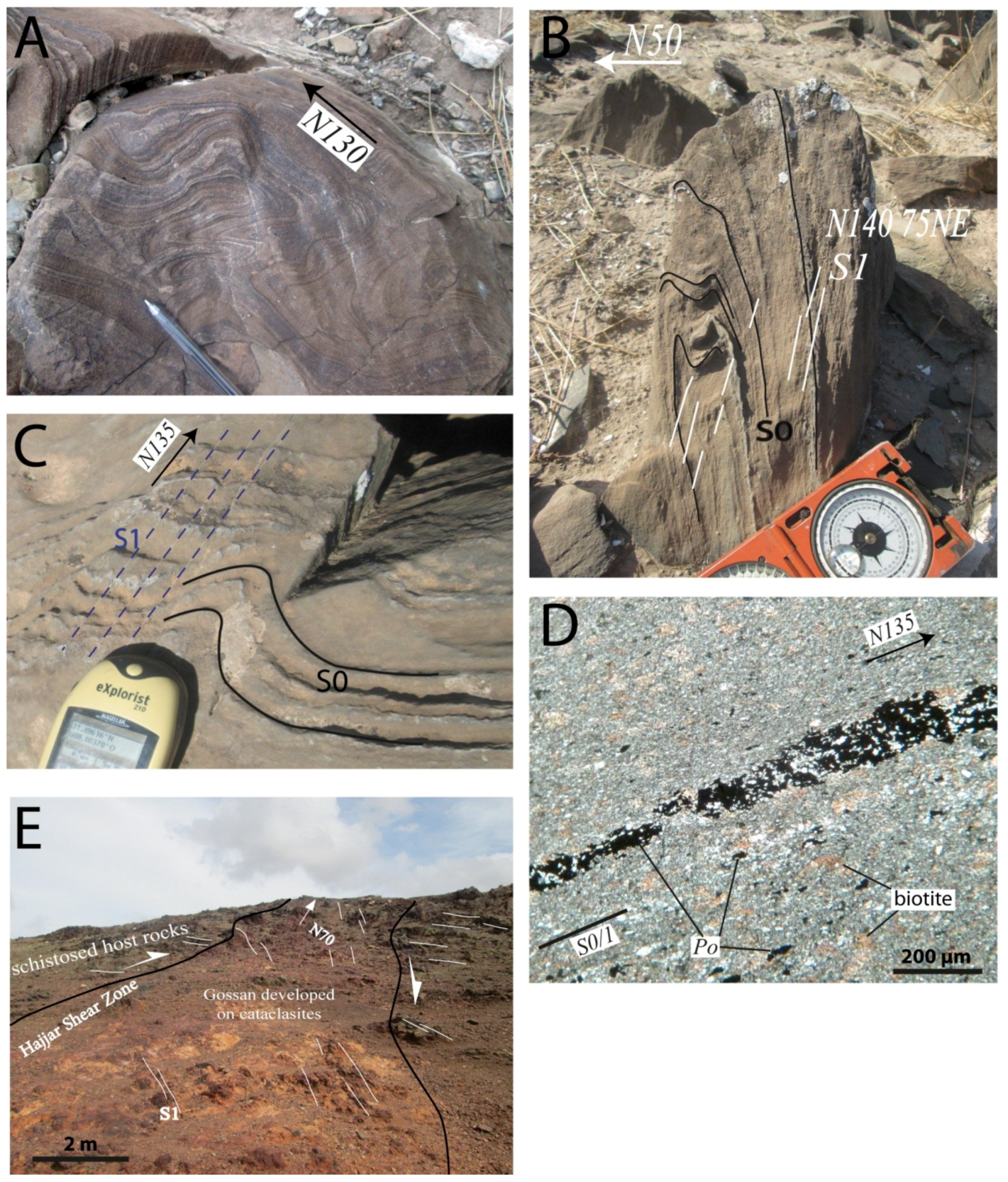
3. Surface Structural Data

The surface outcrops of the N’Fis block and Souktana Massif have been mapped and studied in terms of the strain analysis and micro-tectonics (Figure 2 and Figure 3). The lithologies encountered are pelites alternating with sandy- to pure limestones intruded by felsic and basic sills and dykes (Figure 2). Major volcanic rock bodies correspond to rhyolitic domes and plugs.
Many outcrops of the Imarine Massif present soft-sediment deformation as slumps and convolutes (Figure 3A,B), suggesting slope instabilities within syn-rift sediments. These soft sediment structures are cross-cut by a sub-vertical foliation (S1) which is often oblique with respect to the axial plane of isoclinal folds (Figure 3B). This suggests that most isoclinal and disharmonic folds are slumps, and therefore, that they pre-date the development of the planar axial foliation. This S1 foliation is well-developed though the N’Fis block, with a sub-vertical dip and a NW-SE orientation (Figure 2). This widespread S1 planar fabric corresponds to a P1 axial planar cleavage (Figure 3C), and locally transposes the bedding planes (S0//S1, e.g., Figure 3D).
Locally, the NW-trending S1 is marked by elongated and aligned biotite porphyroblasts, parallel to the stretching of pyrrhotite grains (Figure 3D), suggesting a syn-tectonic growth of biotite. No stretching lineation has been observed in the N’Fis block. Decimeter-scale sinistral WNW to NW-trending vertical ductile shear planes, occurring sparsely and slightly oblique to S1, are responsible for the local deflection of the S1 planes in the Imarine outcrops (six observations plotted on the stereogram, Figure 2). Brittle faults and joints show a predominant NE-trending orientation with a sub-vertical dip (Figure 2). Due to unfavorable rock materials, the precise kinematics of brittle faults are difficult to establish, which enable the reconstruction of the paleo-stress using the right dihedral method, for instance. However, when it can be observed, the apparent map offsets of the NE-trending decimeter-scale faults indicate a dominant dextral sense of shear.
Finally, the Tiferouine outcrop (Figure 2 and Figure 3E) shows a N70-trending gossan which corresponds to the weathered part of a magnetite-bearing body recognized at depth [12]. The supergene alteration appears to overprint an early cataclasite. Along and within the cataclased mineralized body, the S1 foliation orientation is strongly disturbed (Figure 3E), suggesting drag folding along a right-lateral N70-trending wrench fault (also, see Figure 2 for a map view of the drag folding in the Tiferouine area).

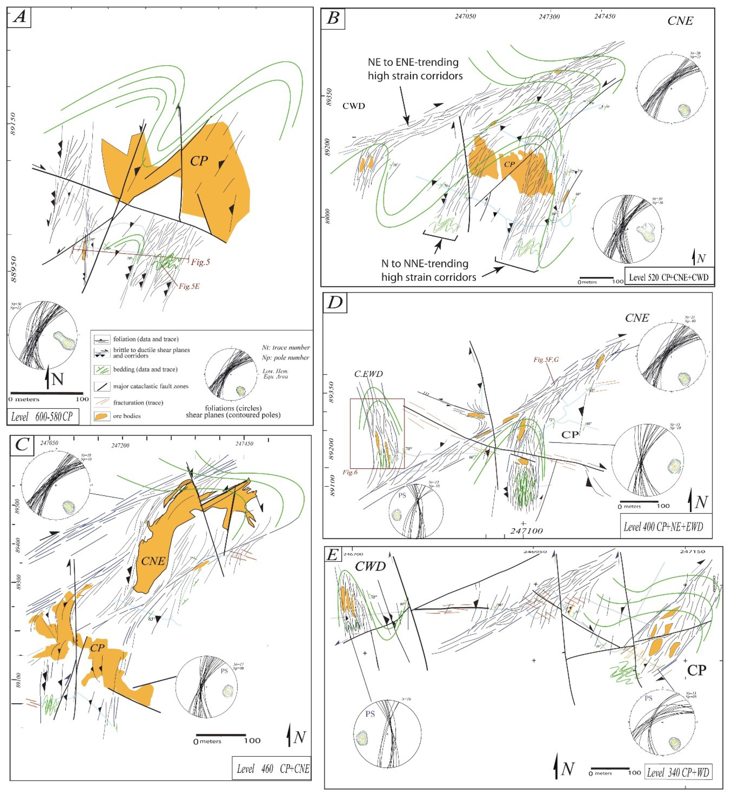
4. Sub-Surface Structural Data from the Hajjar Deposit

Five mine levels have been mapped in the Hajjar deposit (Figure 4). Moreover, we selected two peculiar cross-sections along the galleries to present the meso-scale structures (Figure 5 and Figure 6). The micro scale structure and texture data are summarized in Figure 7 and Figure 8.

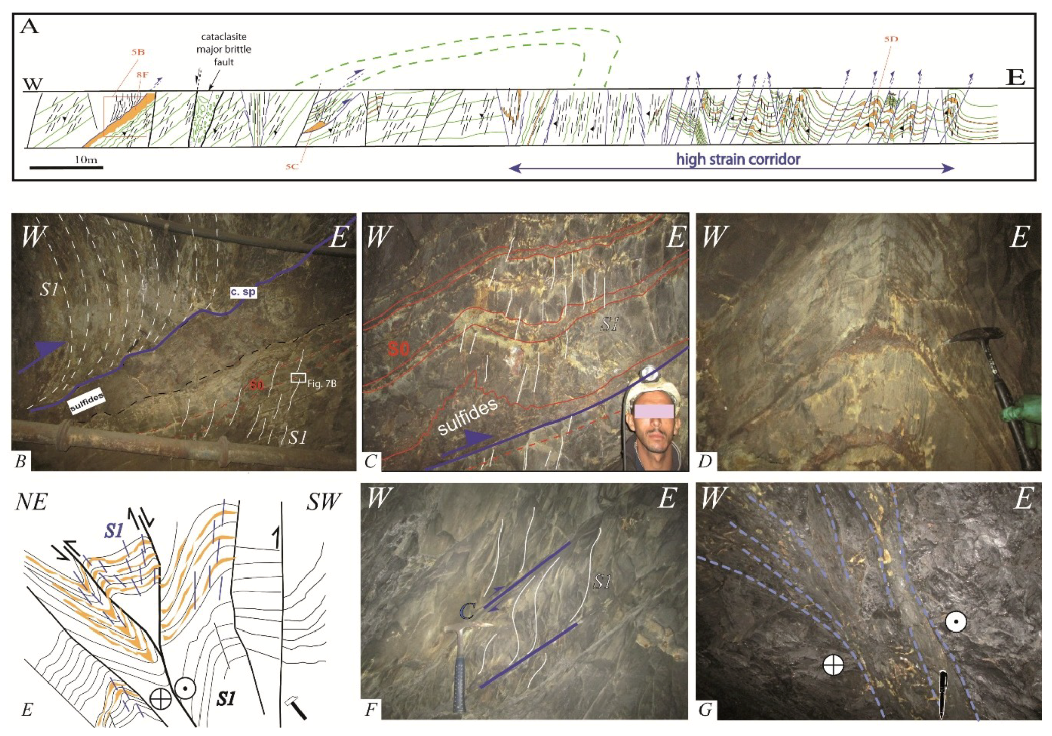
4.1. Strain Pattern and Meso-Scale Structures

Bedding, foliation, and shear planes have been reported at each exploitation level within either host rocks or mineralized bodies (Figure 5). Due to the exploitation, the mineralized bodies are not all accessible yet, and foliation data from Hibti (1993) [23] were used to interpolate the S1 trajectories. The micro petro-structural description of the foliation and shear planes are presented below in the following sections within both host rocks and ore.
The resulting maps show that in the Hajjar MSD, the S1 foliation is near vertical and trends from N0 to N45. With respect to the surface data from the N’Fis block (Figure 2 and Figure 3), NW-oriented foliation has not been measured. The interpolation of the bedding trace emphasizes large-scale tight folding which affects both ore bodies and host rocks. The mineralized bodies have been mapped considering historical grade cut-offs for the exploitation. Geologically, the margins of the ore bodies are much less sharp than those shown on the maps provided in Figure 4. Despite this, the ore body morphologies are distributed among various shapes from a group of lensoid decametric bodies to multi-lobate and “dendritic” shapes (e.g., CP in Figure 4C). It is noteworthy that most of the lensoid decametric bodies, often distributed in clusters, are elongated parallel to the local foliation (e.g., CEWD, CWD, CP in Figure 4D,E).
The brittle deformation marked by fault offsets and joints makes it difficult to locally follow the ductile foliation and shear planes. This brittle deformation is marked by large cataclasite zones (thick lines in Figure 4) with different apparent kinematics that indicate complex and likely diachronous activities. Even though these polyphased cataclasite zones are very important for the continuation, exploration, and production of ore bodies, they require a specific structural study which is outside the scope of this paper which focuses on Variscan ductile strain.
Ductile strain is marked by foliated zones that are heterogeneously distributed, suggesting strain localization in corridors between less deformed areas (Figure 4, Figure 5A and Figure 6A). The strain pattern presents two types of high strain corridors (indicated in Figure 4B): N to NNE-trending and NE to ENE-trending strain corridors.

4.2. The N to NNE-Trending High Strain Corridors

These corridors have been almost fully mapped at all exploitation levels (Figure 4). Two types of strain corridors can be distinguished: the first is characterized by dominant reverse shear planes and folds with an axial planar cleavage S1 (called a “reverse corridor” below, Figure 5A–E), whereas the second corresponds to the development of a strong and penetrative S1 foliation with horizontal stretching lineation without the occurrence of reverse shear planes (called a “flattening corridor” below, Figure 6).
Within reverse corridors, shear planes present dominant reverse rather than strike-slip kinematics. In the map view (Figure 4), the obliquity between S1 and the shear planes, which seems to indicate a sinistral sense of shear, is an artifact as the strike-slip component which is low and dextral when it is observed. The noticeable meso-scale structures are: i) eastward verging thrusts and decollements, most of time using a weak pyrrhotite-rich layer/body as the sole, which is near-parallel to the bedding in the foot-wall (Figure 5A–C). The associated folds in the hanging-walls developed an axial-planar cleavage S1. Typical meter-scale detachment folds, with thickening of the sulfide-rich decollement level, are frequent (Figure 5C), which might explain the “corrugation” observed along the decollement plane (Figure 5B); ii) the high strain corridors are characterized by the development of an intense foliation associated with similar upright NS-oriented folds (Figure 5A and D) which are frequently in association with reverse shear bands responsible for “pop ups” (Figure 5E). Local evidence of the oblique-slip component is provided by oblique stria, the “pop ups” then corresponding to dextral positive flower structures (Figure 5E).
Within the flattening corridors where thrusting is not observed, bedding marked by sulfide-rich ribbons is fully overprinted by the S1 foliation which bears a horizontal NS stretching lineation (Figure 6A). With increasing strain, the rock color changes to a very dark and black tint. To the west, a massive sulfide body is exploited (CEWD). This body is not continuous as it is instead composed of several distinct massive sulfide lenses aligned parallel to S1. The termination of the sulfide lenses is wavy due to the occurrence of small-scale folds of sulfide ribbons or host rocks. This sulfide lens morphology is frequently observed throughout the mine (e.g., Figure 8D). Near the termination, these lenses integrate clasts of host rocks (Figure 6). Cm- to dm-thick veins are abundant along the high strain corridor (Figure 6A). Locally, tips of massive sulfide lenses present triangular veins (or “saddle reef”) at a “triple junction” position with respect to the foliation (Figure 6).

4.3. The NE to ENE-Trending High Strain Corridors

They are typical dextral shear zones, as indicated by drag folds in map view and obliquity between the near vertical S1 and the ductile shear planes (Figure 4 and Figure 5F). The lineation is horizontal along the shear planes which often presents a graphitic/silvery mirror surface. The angle between S1 and the shear planes may be very low to null thus defining a mylonitic foliation locally (e.g., Figure 4C). These dextral shear planes, steeply dipping and trending NE to ENE (Figure 4), may present brittle characteristics as a gouge zone at the outcrop scale (Figure 5G). In the gallery, this type of high strain corridor is generally responsible for slope/wall instabilities, which makes access, oriented sampling, and structural data collection difficult, particularly where the strain corridors intersect large ore bodies (e.g., northern border of the CNE mineralized body, Figure 4C).

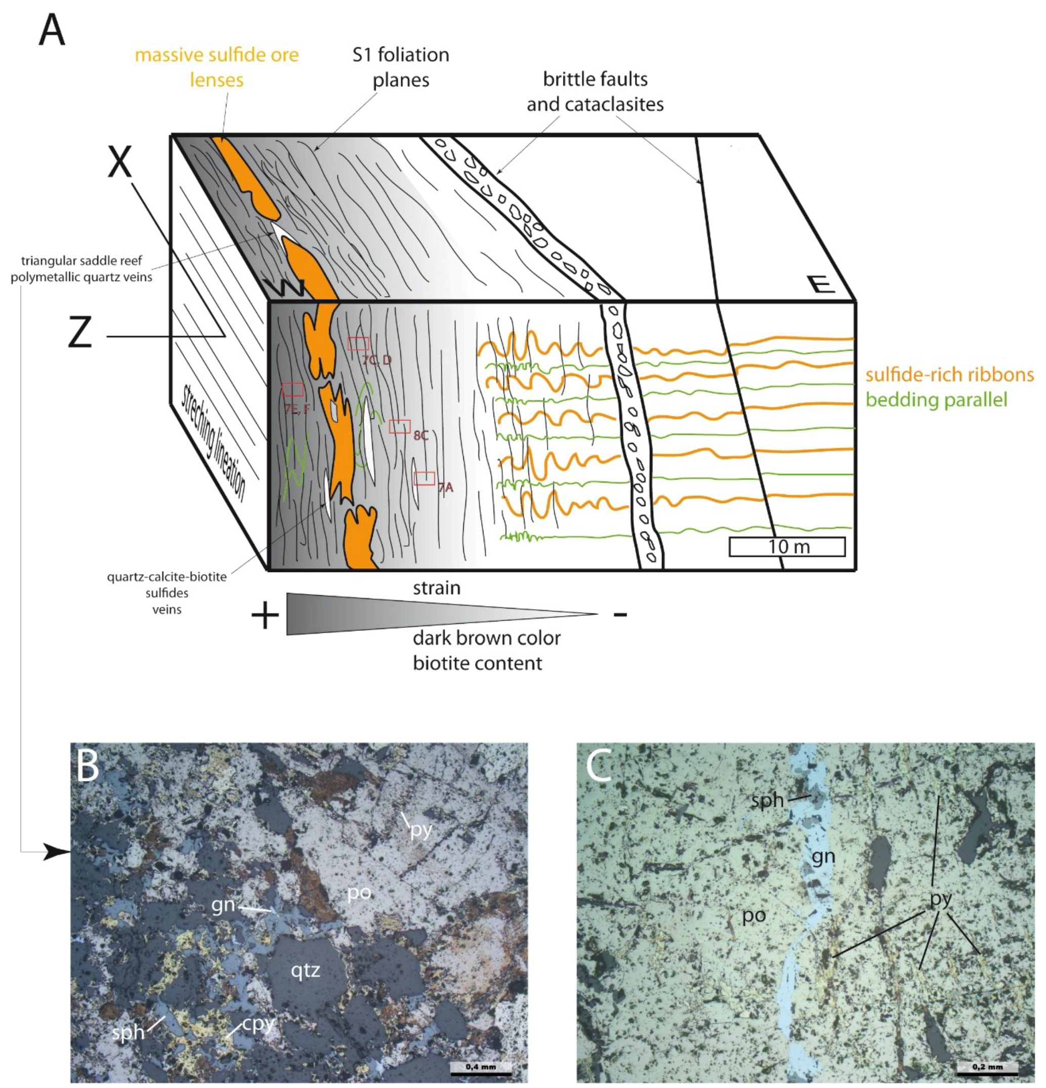
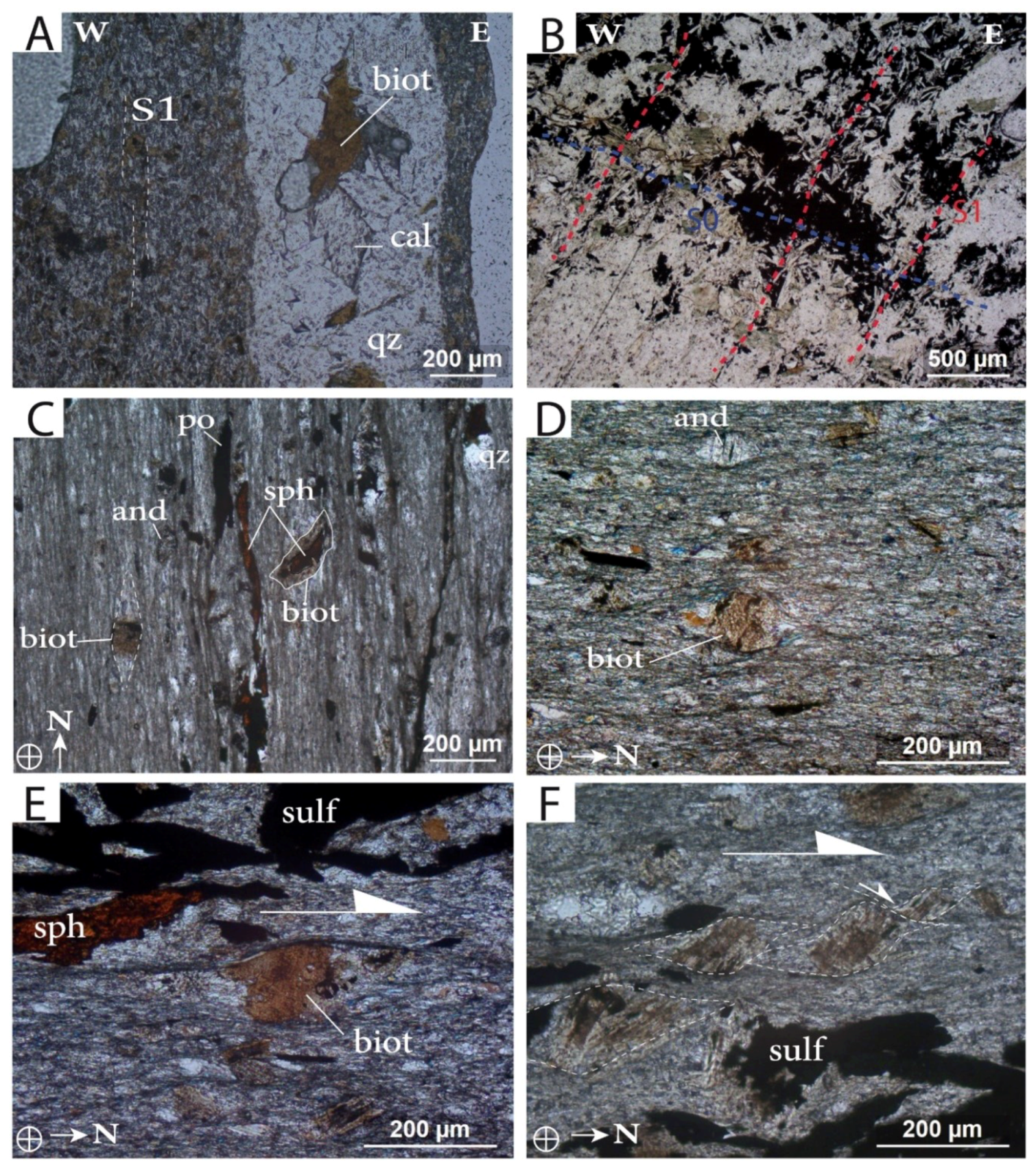
4.4. Microstructures and Textures in the Host Rocks

Oriented thin sections were taken from the Hajjar MSD, especially from the N to NNE-trending high strain corridors described above.
The primary lithologies and associated syn- or diagenetic hydrothermal halos have been metamorphosed and/or altered. This metamorphism appears to be better expressed in high strain corridors, i.e., when the S1 foliation planes are densely represented (e.g., Figure 6A). Two metamorphic assemblages can be distinguished in the metapelites. The first one is comprised of quartz + biotite + andalousite (± calcite). (Figure 7A,C,D). Cordierite has not been observed, but the shape of some porphyroblasts replaced by white mica aggregates indicate the presence of this mineral (e.g., Figure 8E). The second assemblage is made of quartz + chlorite + muscovite (± carbonate). This last assemblage can also be observed in sandy-pelites with sulfide-rich ribbons, where it post-dates and locally replaces the biotites (Figure 7B). Foliation-parallel veinlets are filled with quartz and large biotite crystals associated with calcite in the geodic cavities (Figure 7A).
In areas where the foliation is weakly developed, biotite and andalousite porphyroblasts show a granoblastic “static” texture with a very subtle preferred orientation locally (Figure 7A). With increasing strain, biotite porphyroblasts are generally coarser and present a preferred orientation parallel to the fine-grained S1 foliation, a planar axial surface with micro-folds (Figure 8C). In high strain zones, pressure shadows and strain caps are found around some biotite and andalousite crystals (Figure 7C to F), whereas other biotite crystals remain nearly free of foliation deflection (e.g., a biotite crystal growing around a sphalerite core in Figure 7C). The pressure shadows are generally composed of quartz, muscovite, and chlorite, i.e., the same assemblage constituting the fined-grained foliation (Figure 7D,E). Asymmetric pressure shadows around biotite are common in flattening corridors attesting to a non-coaxial regime, at least locally (e.g., dextral in the CEWD outcrop, Figure 6, Figure 7E,F). Therefore, in high strain and non-coaxial zones, biotite crystals appear as pre-tectonic prophyroblasts, suggesting severe non-coaxial strain increments after the HT/LP metamorphism peak.

4.5. Microstructures and Textures in Sulfides

The internal ductile/plastic strain of the sulfide ribbons and bodies is widespread and high in the Hajjar MSD. This is particularly due to the high content of pyrrhotite within the ore.
Associated with folding, the S1 axial planar cleavage is marked by flattened sulfide ribbons within the XY plane with refractions and hinge thickening (Figure 8A,B). The preferred interpretation is that a refraction mechanism is responsible for this rather than a “bed to bed” flexural slip, because no shear planes have been observed in quartz (Figure 8B). Normal thin sections with XY planes cannot be used to characterize a preferred stretching X direction with respect to the 3D sulfide micro-lens dimensions. Therefore, the strain ellipsoid is mainly oblate and the strain regime is close to pure flattening. In greater detail, different rheological behaviors of the sulfides are expressed along S1, with pyrrhotite behaving much more plastically than chalcopyrite and sphalerite (Figure 8B), which present both a “ductile” and brittle response to the stress. Frequently, the sulfide micro-lenses present an “X-shape” or “chromosome-like” morphology (Figure 8A,C). The elongated sphalerite grains surrounded by pyrrhotite within a foliated silicate matrix (Figure 8C) suggest that the conjugate effects of folding, recrystallization, and rheological contrasts explain this “X” morphology. As mentioned above, this peculiar “X-shape” morphology is also encountered at a larger scale in the edge and tip areas of massive ore bodies (Figure 6 and Figure 8D).
In many places at the Hajjar MSD massive sulfide bodies present an internal planar fabric. Three types of fabrics can be distinguished: i) a planar fabric parallel to the S1 foliation within the host rocks (Figure 8D). In this case, the fabric corresponds to flattened pyrrhotite grains (with various chalcopyrite, sphalerite and galena contents), separated by elongated metamorphic silicate slices/lenses (Figure 8E). The metamorphic assemblage is represented by chlorite and white micas replacing former biotite/andalousite (/cordierite?) blasts (Figure 8E). These silicate slices can be very thin or even absent in the most enriched ore. It is noteworthy that the mechanical twinning of pyrrhotite is regularly distributed in a direction normal to the planar fabric, providing evidence for the tectonic origin of this foliation; ii) mylonitic zones affecting weakly deformed massive sulfides (Figure 8G). These mylonites can be observed where high strain corridors intersect or encompass mineralized bodies. C/S-type structures are common within the sulfide mylonites (Figure 8G). Flattened pyrrhotite grains define the S planes, whereas C planes present finely cataclased sphalerite and chalcopyrite in a foliated silicate gouge; iii) the third planar fabric corresponds to a mineralogical and textural banding marked by alternations of sphalerite-rich and sphalerite-poor ribbons (Figure 8F). For instance, this banding is either parallel to the S1 foliation in the wall rocks or parallel to the bedding planes in the footwall of decollement layers (Figure 5 and Figure 8F). Pyrrhotite grains are elongated with no systematic mechanical twinning. Sphalerite does not show systematic elongation, and the quartz grains are elongated with undulose extinction (Figure 8F). Therefore, the respective part of the syngenetic and diagenetic vs. tectonic processes are still unclear, and cannot be used to explain this banding.

5. Interpretation

5.1. Hajjar Mine and N’Fis Block: One Single Foliation (Not Two)

The rocks of the Hajjar mine are affected by one single flattening XY plane which is near vertical and trends from N0 to N45. The maps of the S1 trajectories (Figure 4) show that the deformation is not homogenous at the mine scale. In the high strain corridors, this XY plane corresponds to a S1 penetrative foliation overprinting the entire rock, whereas in less deformed areas, S1 is a slaty cleavage that is axial planar in similar folds. Host rocks and sulfide bodies present the same silicate metamorphic assemblages (Figure 7 and Figure 8). With respect to this foliation, the qtz + biot and assemblage presents either a “static” granoblastic texture when the strain is low (i.e., weakly developed foliation, Figure 7A) or pre- to syn-tectonic features when the foliation is strongly expressed (Figure 7C to E, Figure 8C). The texture, shapes, and aggregates of the biotite and andalousite (± suspected cordierite) are typical of HT/LP “contact” metamorphism in the hornfels facies. The syn-tectonic assemblage is composed of quartz + chlorite + white micas (± calcite) and partially replaced the former biotite and andalousite blasts (Figure 7B and Figure 8E).
Similarly, surface data from the N’Fis block (Figure 2 and Figure 3) show the occurrence of a single sub-vertical XY plane oriented N130. This flattening plane is a penetrative foliation secant to slumps (Figure 3B) and axial-planar to P1 folds (Figure 3C). Contact metamorphic biotite blasts are elongated parallel to the foliation and appear as flattened sulfide grains (Figure 3D).
Therefore, these data imply that the Hajjar MSD and the N’Fis block are affected by a single foliation which encompasses a HT/LP contact metamorphism. Although a single Variscan foliation was similarly recognized by Dias et al. (2011) [35] at the regional scale, our results disagree with the previously published works on the Hajjar mine/N’Fis area: i) first, two foliations were identified and consequently two successive tectonic events with sub-normal horizontal shortening directions were invoked [12,23]. In particular, the N20-30 dry joints affecting the N’Fis block at the surface (Figure 2) cannot be related to the N0-30 penetrative and ductile foliation observed in the Hajjar mine. Moreover, there has been no direct observation of an early foliation/cleavage in the Hajjar galleries during our study; ii) second, the biotite blasts were interpreted as post-tectonic with respect to the last deformation event [25].

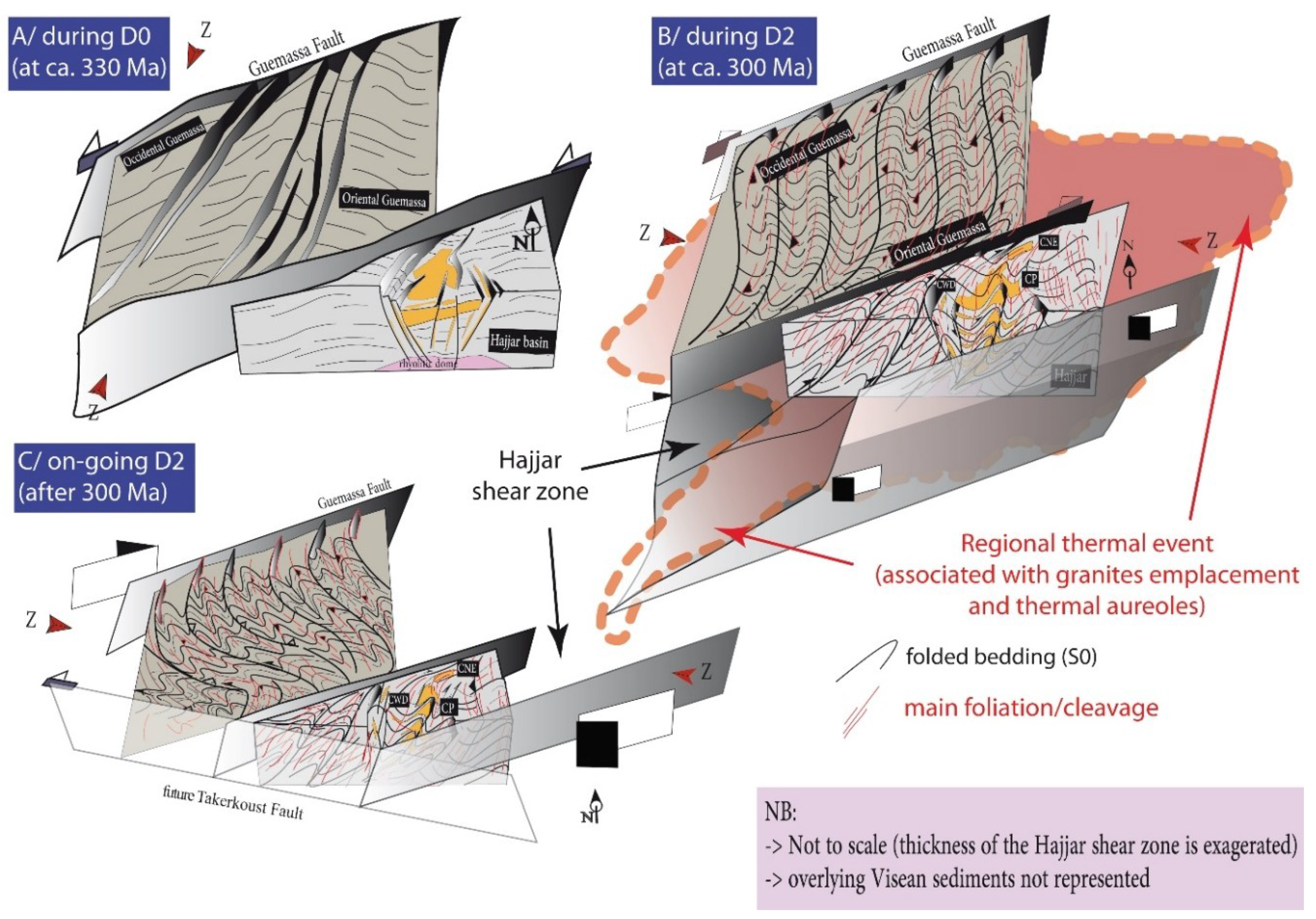
5.2. The Hajjar Mine is Located within a Regional-Scale Shear Zone

The direct consequence of the previous result is the occurrence of a large foliation virgation from the Imarine outcrops to the Hajjar MSD (Figure 2). This virgation in the orogeny is typically caused by wrenching along regional shear zones. Our structural data from the surface (e.g., Tiferouine outcrops, Figure 2 and Figure 3E) and from sub-surface structural maps (Figure 4 and Figure 5) in the Hajjar underground mine fully support the occurrence of a major right-lateral ENE-trending transpressive shear zone at Hajjar.
The strain pattern on the maps show that shear planes are heterogeneously distributed as they are clustered within the shear corridors. Along a broad ENE direction, we identified various types of high strain corridors (see the 2D pattern in Figure 9): i) the N to NNE-trending corridors correspond to either reverse corridors characterized by thrusting and associated folding with a low amount of dextral oblique-slip (Figure 4 and Figure 5A–E) or to flattening corridors characterized by a tight and penetrative foliation with horizontal stretching lineation and a local dextral sense of shear (Figure 6 and Figure 7); ii) The NE to ENE-trending corridors correspond to unequivocal vertical dextral shear zones. The orientation of both strain corridors are connected and form an asymmetric 3D anastomosed pattern that is compatible with a bulk dextral sense of shear along a N60-70 direction (Figure 9). Reverse corridors with vertical thickening indicate that the Hajjar shear zone is transpressive. This result is fully in coherence with previous works dealing with the Western Meseta, in which dominant dextral strike-slip tectonics were clearly identified during the Variscan orogen [35]. However, in the location near the Hajjar mine, a regional scale shear zone of this type has not been previously recognized and constitutes a key structural feature of the Guemassa Hercynian orogenic segment.
The shear planes of the Hajjar MSD present both ductile and brittle features (Figure 5 and Figure 8G, H). The last brittle increments cross-cut and offset the former S1 foliation along the gouge zones (Figure 5G). Asymmetric biotite blasts with pressure shadows filled with the chlorite and white mica assemblage (Figure 7E,F) argue for simple shearing after the thermal peak of the HT/LP contact metamorphism. Lower or retrograde metamorphic conditions during simple shearing are also indicated via the cataclasis of sphalerite and chalcopyrite along the shear planes within mylonitic zones affecting massive sulfides (Figure 8H). Therefore, the Hajjar shear zone records simple shearing increments during and after the development of the widespread S1 foliation.
Last, the Atlasic brittle reactivation of this Hercynian shear zone cannot be ruled out, however it is still difficult to precisely depict this.

5.3. Ore Deformation and Remobilization

As recognized in previous studies [25], our data indicate that the Hajjar mineralization is strongly deformed and metamorphosed. It is affected by folding, foliation and mylonitic bands within a regional scale shear zone. Structures such as pyrrhotite-rich ribbons clearly pre-date the deformation and the HT/LP contact metamorphism (e.g., Figure 6 and Figure 8A). The primary syn- or digenetic mineralization is then strongly reworked by deformation. In particular, at the meter scale, we present clear evidence of tectonic thickening within the fold hinge zone. The wavy termination of the metric-scale massive sulfide lenses parallel to S1 suggests that these lenses were likely thickened by folding before they were flattened within the XY plane of S1 (Figure 6 and Figure 8D). This mechanism is enhanced by the high “plasticity” of pyrrhotite, which is by far the dominant sulfide at Hajjar. The pre-to syntectonic HT/LP metamorphism greatly favor the ductile behavior and recrystallization of sulfides including chalcopyrite and sphalerite. This is observable at the thin section scale, where the tectonic thickening induced the stress-oriented recrystallization of sphalerite, leading to an incipient “banding” of sphalerite-rich/sphalerite-poor slices parallel to S1 (Figure 8C). We suggest that, in Hajjar MSD, this solid-state thickening and remobilization are effective at a larger scale, but further modern textural and mineralogical studies are required in order to be able to investigate this point.
Remobilization of the primary metal stock by fluids (e.g., the fluid state processes and chemical remobilization described by Gilligan and Marshal (1987) [3] is also expressed in the Hajjar MSD. Even though the metal mass balance quantification is outside the scope of this study, the polymetallic veins argue for hydrothermal fluid-assisted remobilization during deformation. In particular, the polymetallic triangular veins at the tips of the massive sulfide lenses indicate such remobilization. This type of vein with a polymetallic assemblage associated with quartz, newly formed sphalerite and galena veinlets, and pyrrhotite replacement by vermicular pyrite (Figure 6B,C), is similar to the so-called “piercement veins” described by authors working on deformed MSD (e.g., [3,38,39,40]). It has been hypothesized that the metamorphic fluids liberated during the prograde HT/LP contact metamorphism (e.g., quartz veins with biotite in Figure 7A), combined with potential advective hot magmatic fluids exsolved from deeper granitic bodies, are able to chemically rework the primary sulfides and concentrate metals into dilatant sites as triple junction veins during the last increments of deformation [3]. Due to high reactive chemistry, the fluid-assisted chemical reworking of primary VMSD is common in many metamorphic contexts other than HT/LP metamorphic conditions (e.g., [41] and references therein).

6. Discussion: Toward an Integrated Tectono-Metamorphic Model for the MSD-Bearing Jebilet and Guemassa Massifs

These interpretations must be discussed in terms of the ages and tectono-metamorphic evolutions established for the Guemassa and Jebilet Massifs; both of these Massifs bear the major MSD in Morocco.
First, syn-sedimentary structures and soft sediment deformation have been identified in the N’Fis block (Figure 3A,B) and in the Hajjar mineralization [23]. These structures are well known within the Visean Sarhlef syn-rift formation in the Jebilet Massif, and correspond to slope instabilities during the opening of the Jebilet basin from 370 to 325 Ma (the D0 transtensive event described by Delchini (2018) [26]). Coeval with this sedimentation, the basin underwent significant bimodal and calc-alkaline magmatism, leading to many intrusions within the sediments and the basement. Consequently, the thermal gradient is very high [26], and primary syn- to diagenetic massive sulfide mineralization occurred within the volcano-sedimentary sequences (Figure 10A). The initial morphology (e.g., normal fault locations and trends, depocenters, etc.) of these basins and sub-basins is not constrained in the Guemassa Massif contrary to the Jebilet Massif where the basins are interpreted as pull-apart systems with NNE-trending normal faults and associated N70E-trending left-lateral strike-slip faults [42]. Therefore, it is likely that the Guemassa Massif and the Hajjar shear zones acted as sinistral strike-slip faults during this Early Carboniferous period (Figure 10A), lateral N to NNE trending normal faults accommodating the formation of local subsiding basins such as the Hajjar one (Figure 10A). However, because it may control the initial MSD distribution, further detailed work is required to specify the Early Carboniferous basin geometries in the Guemassa Massif.
Second, absolute dating of the Hajjar biotites related to thermal aureole metamorphism has been performed by Watanabe (2002) [33] using 40Ar/39Ar dating and yields an approximate age of ca. 301 Ma. This age and the associated HT/LP metamorphic assemblage are compatible with the M2b metamorphism reported in the Jebilet Massif [26,28]. In other words, the S1 foliation and HT/LP metamorphism that we document in the Hajjar MSD and in the N’Fis block within the Guemassa Massif are structurally and temporally similar to the D2b tectono-metamorphic event described in the Jebilet Massif to the north (see the section on geological settings above and [26]). It is noteworthy that this thermal event is not restricted to the Hajjar mine, as it has been traced by Raman Spectroscopy of Carbonaceous Materials geothermometry method (RSCM) throughout the whole N’Fis block [27]. In the Jebilet as in the Guemassa Massifs, it has been reported that this thermal event is the consequence of hidden plutonic intrusions. Our data suggests the presence of fluid-assisted HT/LP “contact” metamorphism (Figure 7A). Therefore, the vigorous advection of hot fluids exsolved from melts and/or which come from metamorphic devolatilization may also partly explain the large extent of this HP/LP metamorphism observed in the Guemassa and Jebilet Massifs close to 300 Ma. This regional thermal anomaly is represented in Figure 10B. No former foliation/cleavage has been observed in either the N’Fis block or in the Hajjar mine, suggesting that the D2a/M2a event identified by Delchini (2018) [26] in the Jebilet Massif is not expressed in the Guemassa Massif. This is in agreement with the fact that the D2a/M2a event, which reaches the garnet-staurolite amphibolite facies, is poorly represented in the Jebilet Massif, and better expressed northward in the Rehamna Massif. Thus, the S1 foliation/cleavage characterized in this study matches the S2b foliation identified in the Jebilet Massif to the north by Delchini et al. (2016) [28]. Biotites related to the HT/LP metamorphism are not post-kinematic, as proposed by Hibti (1993) [23]. They are pre- to syn-kinematic, which implies that deformation occurred during the peak of the HT/LP “contact” metamorphism (Figure 9B). Based on the biotite blasts vs. strain relationship, we suggest that during the HT peak, the deformation was predominantly coaxial before shifting to a bulk non-coaxial regime.
Third, during the Early Permian, the D2 event identified in the Jebilet Massif ended with transpressive conjugate regional shear zones, oriented NE/ENE and SE/SSE with a dextral and sinistral (e.g., the MSZ, Figure 1) sense of shear respectively (i.e., the D2c event described by Delchini, 2018) [26]. This led to the development of a regional scale “flower structuration” of the Jebilet Massif. This strain localization along the shear zones appears to post-date the HT/LP contact metamorphism. Our data from the Guemassa Massif are fully compatible with this scenario (Figure 10C): the Hajjar regional shear zone we recognized in this study appears to be one of the dextral shear zones responsible for the large virgation of the main foliation planes. As observed in the Jebilet Massif, this shear zone corresponds to a progressive strain localization during the retrograde metamorphism when the D2 event ended. Last, as proposed by Dias et al. (2011) [35], conjugate WNW-ESE trending sinistral shear zones activated as the Lalla Takerkoust fault (Figure 10 C). This sinistral wrench zone accentuated and is responsible for the virgation of the S1 foliation, resulting in the “anarchic” WNW-orientation of the foliation observed through the N’Fis block.

7. Conclusion

The Guemassa Massif and the Hajjar base-metal massive sulfide deposit have been affected by a single foliation during a major Late Carboniferous-Early Permian Hercynian tectonic event. This foliation is strongly affected and deflected by regional scale shear zones such as the Hajjar N70-trending and right-lateral shear zone. Structural mapping in the Hajjar mine demonstrates that the Hajjar shear zone is complex with anastomosing shear plane patterns combined with thrusting and folding. This deformation is partially coeval, with a large thermal anomaly responsible for the HT/LP metamorphism. The tectono-metamorphic evolution of the Oriental Guemassa Hercynian segment is highly compatible with the evolution depicted for the Jebilet Massif. Strain under a high heat flux favored the deformation of the massive sulfides bodies which partly underwent fluid-assisted remobilization in the Hajjar mine. The tectonic thickening of the mineralization is observed at the meter scale, and must be re-examined at a larger scale.

Author Contributions

S.A. and Y.B. conceptualized both the study and the final model and wrote the original draft. L.B (Lakhlifi Badra) and L.B. (Luc Barbanson) reviewed and edited the draft. M.O., A.K., M.Z., L.M. gave their validation, Funding acquisition and project administration.

Funding

The PhD thesis of S. Admou has been partly funded by the “Office Mediterannéen de la Jeunesse” through a partnership between Orleans University (France) and Moulay Ismael University (Meknès, Morocco).

Acknowledgments

We are grateful to S. Janiec from ISTO and X. Le Coz from Geosciences Rennes who performed high quality thin sections. Our discussion with S. Delchini was greatly appreciated. We thank the reviewers and specially R. Dias for very fruitful and constructive review. The Guest Editor A. Chauvet is also thanked for inviting us to submit our work.

Conflicts of Interest

The authors declare no conflict of interest.

References

  1. Cawood, P.A.; Hawkesworth, C.J. Temporal relations between mineral deposits and global tectonic cycles. In Ore Deposits in an Evolving Earth; Jenkin, G.R.T., Lusty, P.A.J., Mcdonald, I., Smith, M.P., Boyce, A.J., Wilkinson, J.J., Eds.; Geological Society of London: London, UK, 2013; pp. 9–21. [Google Scholar]
  2. Graf, J.; Skinner, B. Strength and deformation of pyrite and pyrrhotite. Econ. Geol. 1970, 65, 206–215. [Google Scholar] [CrossRef]
  3. Marshall, B.; Gilligan, L.B. An introduction to remobilisation: information from ore-body geometry and experimental considerations. Ore Geol. Rev. 1987, 2, 87–131. [Google Scholar]
  4. Marshall, B.; Spry, P.G. Discriminating between regional metamorphic remobilization and syntectonic emplacement in the genesis of massive sulfide ores. Rev. Econ. Geol. 1998, 11, 39–80. [Google Scholar]
  5. Marignac, C.; Diagana, B.; Cathelineau, M.; Boiron, M.-C.; Banks, D.; Fourcade, S.; Vallance, J. Remobilisation of base metals and gold by Variscan metamorphic fluids in the south Iberian pyrite belt: evidence from the Tharsis VMS deposit. Chem. Geol. 2003, 194, 143–165. [Google Scholar] [CrossRef]
  6. Chauvet, A.; Onézime, J.; Charvet, J.; Barbanson, L.; Faure, M. Syn- to late-tectonic stockwork emplacement within the spanish section of the iberian pyrite belt: Structural, textural, and mineralogical constraints in the tharsis and la zarza areas. Econ. Geol. 2004, 99, 1781–1792. [Google Scholar] [CrossRef]
  7. Barrie, C.D.; Boyle, A.P.; Prior, D.J. An analysis of the microstructures developed in experimentally deformed polycrystalline pyrite and minor sulphide phases using electron backscatter diffraction. J. Struct. Geol. 2007, 29, 1494–1511. [Google Scholar] [CrossRef]
  8. Barrie, C.D.; Boyle, A.P.; Cook, N.J.; Prior, D.J. Pyrite deformation textures in the massive sulfide ore deposits of the Norwegian Caledonides. Tectonophysics 2010, 483, 269–286. [Google Scholar] [CrossRef]
  9. Barrie, C.D.; Peare, M.A.; Boyle, A.P. Reconstructing the pyrite deformation mechanism map. Ore Geol. Rev. 2011, 39, 265–276. [Google Scholar] [CrossRef]
  10. Reddy, S.M.; Hough, R.M. Microstructural evolution and trace element mobility in Witwatersrand pyrite. Contrib. Mineral. Petrol. 2013, 166, 1269–1284. [Google Scholar] [CrossRef]
  11. Bernard, A.J.; Maier, O.W. Aperçus sur les amas sulfurés Massifs des hercynides Marocaines. Miner. Depos. 1988, 23, 104–114. [Google Scholar] [CrossRef]
  12. Hibti, M. Les amas Sulfurés des Guemassa et des Jebilet (Meseta Sud-Occidentale, Maroc): Temoins de L’hydrothermalisme Précoce dans le Bassin Mesetien. Ph.D Thesis, University Cadi Ayyad, Marrakech, Morocco, 2001. [Google Scholar]
  13. Belkabir, A.; Gibson, H.L.; Marcoux, E.; Lentz, D.; Rziki, S. Geology and wall rock alteration at the Hercynian Draa Sfar Zn–Pb–Cu massive sulphide deposit, Morocco. Ore Geol. Rev. 2008, 33, 280–306. [Google Scholar] [CrossRef] [Green Version]
  14. Marcoux, E.; Belkabir, A.; Gibson, H.L.; Lentz, D.; Ruffet, G. Draa Sfar, Morocco: A Visean (331 Ma) pyrrhotite-rich, polymetallic volcanogenic massive sulphide deposit in a Hercynian sedimentdominant terrane. Ore Geol. Rev. 2008, 33, 307–328. [Google Scholar] [CrossRef] [Green Version]
  15. Moreno, C.; Sáez, R.; González, F.; Almodóvar, G.; Toscano, M.; Playford, G.; Alansari, A.; Rziki, S.; Bajddi, A. Age and depositional environment of the Draa Sfar massive sulfide deposit, Morocco. Miner. Depos. 2008, 43, 891–911. [Google Scholar] [CrossRef]
  16. Ben aissi, l. Contribution à L’étude Gîtologique des Amas Sulfurés Polymétalliques de Draa Sfar et de Koudiat Aïcha: Comparaison avec les Gisements de Ben Slimane et de Kettara (Jebilet Centrales, Maroc Hercynien). Ph.D Thesis, University Cadi Ayyad, Marrakech, Morocco, 2008. [Google Scholar]
  17. Lotfi, F.; Belkabir, A.; Brown, A.C.; Marcoux, E.; Brunet, S.; Maacha, L. Geology and Mineralogy of the Hercynian Koudiat Aïcha Polymetallic (Zn-Pb-Cu) Massive Sulfide Deposit, Central Jebilet, Morocco. Explor. Min. Geol. 2008, 17, 145–162. [Google Scholar] [CrossRef]
  18. Essaifi, A. Relations entre Magmatisme-Déformation et al.tération Hydrothermale: L’exemple des Jebilet Centrales (Hercynien, Maroc). Ph.D Thesis, Unversity of RennesI, Rennes, France, 1995. [Google Scholar]
  19. Essaifi, A.; Hibti, M. The hydrothermal system of Central Jebilet (Variscan Belt, Morocco): A genetic association between bimodal plutonism and massive sulphide deposits? J. Afr. Earth Sci. 2008, 50, 188–203. [Google Scholar] [CrossRef]
  20. Essaifi, A.; Goodenough, K.M.; Lusty, P.A.J.; Outigua, A. Microstructural and Textural Evidence for Protracted Polymetallic Sulphide Mineralization in the Jebilet Massif (Variscan Belt of Morocco). Min. Resour. Sustain. World 2015, 1–5, 1603–1606. [Google Scholar]
  21. Lusty, P.A.J.; Goodenough, K.M.; Essaifi, A.; Maacha, L. Developing the lithotectonic framework and model for sulfide mineralization in the Jebilet Massif, Morocco: implications for regional exploration. In Mineral Resources in a Sustainable World, Proceedings of the 13th Biennial SGA Meeting, Nancy, France, 24–27 August 2015; André-Mayer, A.S., Cathelineau, M., Muchez, P.h., Pirard, E., Sindern, S., Eds.; Society for Geology Applied to Mineral Deposits (SGA): Genéve, Switzerland, 2015; pp. 1635–1638. [Google Scholar]
  22. N’Diaye, I.; Essaifi, A.; Dubois, M.; Lacroix, B.; Goodenough, K.M.; Maacha, L. Fluid flow and polymetallic sulfide mineralization in the Kettara shear zone (Jebilet Massif, Variscan Belt, Morocco). J. Afr. Earth Sci. 2016, 119, 17–37. [Google Scholar] [CrossRef] [Green Version]
  23. Hibti, M. L’amas Sulfuré de Hajjar, Contexte Géologique de mie en Place et déformations Superposées (Haouz de Marrakech, Méseta Sudoccidentale, Maroc). Ph.D Thesis, University Cadi Ayyad, Marrakech, Morocco, 1993. [Google Scholar]
  24. Zouhry, S. Étude Métallogénique D’un amas Sulfuré viséen à Zn Pb Cu: cas de Hajar, Guemassa, Maroc. Ph.D Thesis, Ecole polytechnique de Montréal, Montréal, Canada, 1999. [Google Scholar]
  25. Hibti, M.; Marignac, C. The Hajjar deposit of Guemassa (SW Meseta, Morocco): A metamorphosed syn-sedimentary massive sulfide ore body of the Iberian type of volcano-sedimentary massive sulfide deposits. In Mineral Deposits at the Beginning of the 21st Century, Proceedings of the Joint Sixth Biennial SGA-SEG Meeting, Krakow, Poland, 26–29 August 2001; A.A. Balkema: Lisse, The Netherlands, 2001; pp. 281–284. [Google Scholar]
  26. Delchini, S. Etude Tectono-Thermique D’un Segment Orogénique Varisque à Histoire GéOlogique Complexe: Analyse Structurale, Géochronologique et Thermique du Massif des Jebilet, de L’extension à la Compression. Ph.D Thesis, University of Orléans, Orléans, France, 2018. [Google Scholar]
  27. Delchini, S.; Lahfid, A.; Ramboz, C.; Branquet, Y.; Maacha, L. New Peak Temperature Constraints using RSCM Geothermometry on the Hajjar Zn-Pb-Cu Mine and its Surroundings (Guemassa Massif, Morocco). In Proceedings of the 13th SGA Biennial Meeting, Nancy, France, 24–27 August 2015. [Google Scholar]
  28. Delchini, S.; Lahfid, A.; Plunder, A.; Michard, A. Applicability of the RSCM geothermometry approach in a complex tectono-metamorphic context: The Jebilet Massif case study (Variscan Belt, Morocco). Lithos 2016, 256, 1–12. [Google Scholar] [CrossRef]
  29. Haimmeur, J. Contribution à L’étude de L’environnement Volcano-Sédimentaire et du Minerai de Douar Lahjar (Guemassa, Maroc), Lithologie, Paléo-Volcanisme, Géochimie et Métallogénie. Ph.D Thesis, École Nationale Supérieure de Géologie, Nancy, France, 1988. [Google Scholar]
  30. Raqiq, H. Le bassin Carbonifère des Guemassa (Meseta Sud occidentale, Maroc): Lithostratigraphie, sédimentologie et évolution structurale. Ph.D Thesis, University Cadi Ayyad, Marrakech, Morocco, 1997. [Google Scholar]
  31. Ouadjou, A. Pétrographie, Géochimie et Structure des Roches Magmatiques Antéschisteuses des Massifs Hercyniens des Guemassa et Souktana. Ph.D Thesis, University Cadi Ayyad, Marrakech, Morocco, 1997. [Google Scholar]
  32. Ed Debi, A.; Saquaque, A.; Kersit, M.; Chbiti, A. L’amas sulfuré de Hajar (Guemassa, Maroc). Chronique de la Recherche Minière 1998, 531–532, 45–54. [Google Scholar]
  33. Watanabe, Y. 40Ar/39Ar geochronologic constraints on the timing of massive sulfide and vein-Type Pb-Zn mineralization in the Western Meseta of Morocco. Econ. Geol. 2002, 97, 147–157. [Google Scholar] [CrossRef]
  34. Soulaimani, A. L’évolution structurale des Massifs hercyniens du Haouz de Marrakech: Guemassa- N’fis (Maroc). Ph.D Thesis, University Cadi Ayyad, Marrakech, Morocco, 1991. [Google Scholar]
  35. Dias, R.; Hadani, M.; Leal Machado, I.; Adnane, N.; Hendaq, Y.; Madih, K.; Matos, C. Variscan structural evolution of the western High Atlas and the Haouz plain (Morocco). J. Afr. Earth Sci. 2011, 61, 331–342. [Google Scholar] [CrossRef]
  36. Hoepffner, C.; Soulaimani, A.; Piqué, A. The Moroccan Hercynides. J. Afr. Earth Sci. 2005, 43, 144–165. [Google Scholar] [CrossRef]
  37. Saadi, M.; Hilali, E.A.; Bensaîd, M.; Boudda, A.; Dahmani, M. Carte géologique du Maroc, échelle 1:1 000 000. Notes Mém. Serv. Géol. Maroc. 1985. Available online: https://geodata.mit.edu/catalog/mit-gfcc2renabn5c (accessed on 6 October 2018).
  38. Pedersen, F.D. Remobilization of the massive sulfide ore of the Black Angel Mine, central West Greenland. Econ. Geol. 1980, 75, 1022–1041. [Google Scholar] [CrossRef]
  39. Maiden, K.J.; Chimimba, L.R.; Smalley, T.J. Cuspate ore-wall rock interfaces, piercement structures and the localization of some sulfide ores in deformed sulfide deposits. Econ. Geol. 1986, 81, 1464–1472. [Google Scholar] [CrossRef]
  40. Plimer, I.R. Remobilization in high-grade metamorphic environments. Ore Geol. Rev. 1987, 2, 231–245. [Google Scholar] [CrossRef]
  41. Gu, L.; Zheng, Y.; Tang, X.; Zaw, K.; Della-Pasque, F.; Wu, C.; Tian, Z.; Lu, J.; Li, X.; Yang, F.; et al. Copper, gold and silver enrichment in ore mylonites within massive sulphide orebodies at Hongtoushan VHMS deposit, NE China. Ore Geol. Rev. 2007, 30, 1–29. [Google Scholar] [CrossRef]
  42. Aarab, E.M.; Beauchamp, J. Le magmatisme carbonifère pré-orogénique des Jebilet centrales (Maroc). Précisions pétrographiques et sédimentaires. Implications géodynamiques. CR Acad. Sci. Paris 1987, 304, 169–174. [Google Scholar]
Figure 1. (A) Structural map of Morocco showing the major bounding-fault domains. The arrows indicate the sense of shear for the late Variscan structures (modified from Hoepffner et al., 2005 [36]); (B) Geological and structural map of the central domain of the Hercynian belt (from [35,37]. The main foliation trajectories in the Jebilet are reported from Essaifi, 1995 [18]). Within the Guemassa Massif, the Hajjar base metal deposit is located in the N’Fis block which presents an “anarchic” foliation orientation with respect to the bulk N to NNE trend reported in the Jebilet, Occidental Guemassa and western High Atlas Variscan Massifs.
Minerals 08 00435 g001
Figure 2. Geological map and surface structural data of the N’Fis block and the Souktana Massif. All of the sedimentary formations are Carboniferous in age and are affected by both metamorphism and deformation. IF: Imarine Fault; TF: Lala Takerkoust Fault; AKF: Ait Khaled Fault. The interpolation of the foliation/shear planes is also supported by sub-surface structural data from underground mine works (cf. infra). Note that the S1 trajectories depict a dextral drag fold against the ENE-trending Tiferouine mineralized body.
Minerals 08 00435 g002
Figure 3. Structures observed in the outcrops. (A) syn-sedimentary and soft sediment deformation occurring as slumps and convolutes are widespread in the sandy limestones of the N’Fis block; (B) obliquity between the S1 foliation plane and recumbent fold axial plane suggests that some isoclinal folds are former slumps rather than P1 folds; (C) NW-trending S1 foliation plane developed within the P1 hinge zone; (D) thin sections (cross polars normal to foliation) of metapelite with sulfide ribbons (Po: pyrrhotite) from the N’Fis block. The bedding plane is transposed by the S1 foliation plane, the sulfide ribbon and patches disseminated in the matrix are flattened. Biotite porphyroblasts are elongated broadly parallel to the foliation plane; (E) mineralized Tiferouine body (see location in Figure 2) with an associated gossan inside an ENE-trending dextral shear zone evidenced by cataclasites and the re-orientation of S1.
Minerals 08 00435 g003
Figure 4. Structural maps of the five main exploitation levels (decreasing altitude from A to E) in the Hajjar mine. High strain corridors are marked by the development of dense foliation and shear planes. The light blue traces are galleries. The coordinates are taken from the mine’s own system. Note that the scale is slightly different for each level. The following acronyms are used for the ore bodies (translated from French): CP = main body; CNE = north-eastern body; CWD = western body; CEWD = extreme western body. The CP ore body has been intensively exploited and some zones are no longer accessible, structural data from Hibti (1993) [23] were then added and carefully projected in these areas (see text for explanation).
Structural maps of the five main exploitation levels (decreasing altitude from A to E) in the Hajjar mine. High strain corridors are marked by the development of dense foliation and shear planes. The light blue traces are galleries. The coordinates are taken from the mine’s own system. Note that the scale is slightly different for each level. The following acronyms are used for the ore bodies (translated from French): CP = main body; CNE = north-eastern body; CWD = western body; CEWD = extreme western body. The CP ore body has been intensively exploited and some zones are no longer accessible, structural data from Hibti (1993) [23] were then added and carefully projected in these areas (see text for explanation).
Minerals 08 00435 g004
Figure 5. Structures and deformation of the Hajjar ore deposit. A to E are from the N to NNE-trending high strain “reverse”corridors; F and G are from the NE to ENE-trending high strain corridors. (A) Cross-section along the gallery from level 600-580 (see location in Figure 4A). S0 is shown in green, S1 is in black, the brittle to ductile shear planes are given in blue, the main massive sulfide bodies are shown in orange. The section is located within the footwall of the CP and is mainly composed of stratified greso-pelites and tuffs with mm- to cm-thick sulfide ribbons (containing mostly pyrrhotite and pyrite with a small amount of chalcopyrite) with no economic interest. The intensity/spacing of the foliation and high frequency of the shear planes can be used to depict the high strain corridors. Most of the brittle to ductile shear planes have an apparent reverse component: (B) an east-verging thrust developed within a pyrrhotite-rich massive sulfide deposit acting as a decollement layer. In the hanging-wall, the bedding is not observed whereas the S1 cleavage is curved by top-to-the-east drag folding. Both massive sulfide wallrocks are corrugated (c. sp: corrugated shear plane); (C) Detachment fold above a pyrrhotite-rich sulfide layer thickened within the core of a disharmonic fold hinge The S1 axial planar foliation is well-developed in the hanging-wall; (D) Upright similar fold with associated axial planar S1 cleavage. The pyrrhotite-rich red ribbons are extremely thinned in the limbs and thickened within the hinge zone; (E) Positive flower structure associated with similar drag folds and S1 cleavage (line drawing from level 600-580, Figure 4A). Along the N15E-trending faults, high dipping stria show that the reverse component is dominant relatively to the dextral strike-slip one; (F) Ductile dextral NE-trending near the vertical shear planes (C) and associated S1 foliation within a NE-trending right-lateral high strain corridor in meta-siltstones (location CNE area, Figure 4D); (G) ENE-trending steep dextral shear zones marked by foliated gouges and various branches (sense of shear is determined in the gallery roof, location in Figure 4D).
Minerals 08 00435 g005
Figure 6. Outcrops of the extreme western body (CEWD) gallery, a typical N-trending “flattening” corridor. (A) 3D man-made sketch of the CEWD cross-section located in Figure 6A. The exploited massive ore bodies correspond to meter-scale lenses aligned within a high strain zone marked by an intense foliation in dark host rocks with high biotite and sulfide content. X and Z are the long and short axis of the strain ellipsoid respectively; (B,C) Thin-section photographs of the triangular veins developed at the massive ore lenses termination (RL). The vein is mainly filled with quartz associated with a polymetallic assemblage. Pyrrhotite is replaced by pyrite along cracks (B,C) and sphalerite/galena (± chalcopyrite) veinlets crosscut the former pyrrhotite and arsenopyrite grains (not shown).
Minerals 08 00435 g006
Figure 7. Thin section microphotographs of the S1 foliation and associated porphyroblasts within the Hajjar host rocks. A, C, D, E and F are from the flattening corridors; B is from the reverse corridors. (A) Quartz (qz), calcite (cal) and biotite (biot) vein parallel to the incipient S1 foliation, vertical section, see location in Figure 6, NAPL. The host rock presents a fine-grained granoblastic texture composed of biotite and andalousite grains with a local preferred orientation defining an incipient foliation plane; (B) Footwall of the thrust (see location in Figure 5) with the So plane marked by sulfide-rich ribbons (in blue) and discrete S1 planes (in red) characterized by muscovite (white laths) crystallization (NAPL). Please note that the non-oriented biotite (i.e., “static”) porphyroblasts are replaced by chlorite (pale green); (CF) Horizontal thin sections parallel to the stretching lineation showing the main foliation plane S1 marked by elongated sulfides (sulf) and particularly pyrrhotite (po) and sphalerite (sph); see location in Figure 6. Like the fine-grained foliation, the pressure shadows and caps around the andalousite (and) and biotite (biot) grains are composed of quartz, white micas, chlorite and local carbonates. In the high strain area, asymmetric pressure shadows around the biotite indicate a non-coaxial regime with a dextral sense of shear (E,F).
Minerals 08 00435 g007
Figure 8. Deformation and textures of the sulfides in the Hajjar deposit. (A) The folding and associated S1 foliation of fine-grained sediments containing early sulfide-rich ribbons parallel to the bedding (S0). Note the cleavage refraction and thickening of the hinge zone due to the plastic behavior of pyrrhotite; (B) Details of A with pyrrhotite flowing along the stretching direction whereas the behavior of chalcopyrite and sphalerite is less plastic. A metamorphic assemblage mainly composed of muscovite and chlorite (± biotite) grows parallel to S1; (C) Micro-fold affecting a sphalerite and pyrrhotite-rich thin ribbon (CEWD, location in Figure 6A). The axial planar cleavage S1 is marked by the stretching of sulfides and elongated biotite blasts; (D) Massive sulfide lenses separated by strongly foliated host rock slices (south of CP, altitude 500 m). The ore bodies are internally banded parallel to the S1 foliation; (E) Texture of deformed pyrrhotite-rich massive sulfide (RL) parallel to the S1 foliation. The dark grey areas correspond to a muscovite/chlorite (replacing biotite locally) assemblage. Andalousite or cordierite porphyroblast ghosts are replaced by white micas (arrow); (F) textural and mineralogical banding within a massive sulfide body in the sole thrust (see location Figure 5A,B). Note the elongation of the quartz grains; (G) Massive sulfide sample affected by ductile shearing and mylonitization (SE part of the CP, level 400, the local name is “la bande Sud-Est”); (H) Details of G, thin section, RL. The sulfide mylonites present typical C/S structures. It should be noted that sphalerite appears to be “localized” in the C planes. The sample view from the bottom shows a dextral sense of shear.
Minerals 08 00435 g008
Figure 9. Simplified and conceptual map view model of the internal strain pattern within the Hajjar transpressive right-lateral shear zone (see text for explanation).
Minerals 08 00435 g009
Figure 10. Tectono-metamorphic model of the Hajjar shear zone and associated MSD. The name of the tectonic events (D0, D2) corresponds to the tectonic events that have recently been established for the Jebilet Massif by Delchini (2018) [26]. D1 has not been identified in this study. See text for explanations.
Minerals 08 00435 g010

