Article

Sedimentary Stylolites Roughness Inversion Enables the Quantification of the Eroded Thickness of Deccan Trap Above the Bagh Group, Narmada Basin, India

1
Department of Geology, Chunaram Gobinda Memorial Government College, Purulia 723131, India
2
Laboratoire des Fluides Complexes et Leurs Réservoirs, Universite de Pau et des Pays de l’Adour, E2S UPPA, CNRS, LFCR, 64000 Pau, France
3
Department of Earth Sciences, Indian Institute of Technology Kanpur, Kanpur 208016, India
*
Author to whom correspondence should be addressed.
Minerals 2025, 15(8), 766; https://doi.org/10.3390/min15080766
Submission received: 30 May 2025 / Revised: 26 June 2025 / Accepted: 15 July 2025 / Published: 22 July 2025

Abstract

Stylolites, common dissolution surfaces in carbonate rocks, form due to localized stress-induced pressure-solution during burial compaction or tectonic contraction. Their morphology and growth are influenced by dissolution kinetics, rock heterogeneity, clay content, burial depth, stress evolution, diagenesis, and pore fluid availability. This study applies the stylolite roughness inversion technique (SRIT), a proven paleopizometer that quantifies the principal vertical stress (σv = σ1) prevailing in strata in the last moments of bedding-parallel stylolites (BPS) formation, to the Late Cretaceous Bagh Group carbonates in the Narmada Basin, India, to estimate their burial paleo-depth. Using the Fourier Power Spectrum (FPS), we obtained 18 σ1 values from a collection of 30 samples, enabling us to estimate paleo-burial depths for the Bagh Group ranging from 660 to 1320 m. As the Bagh Group burial history is unknown, but as there is no subsequent sedimentary deposition above it, we relate this ca. 1.3 km burial depth to the now eroded thickness of the deposits related to Deccan volcanism at the end of the Cretaceous time, implying a quasi-instantaneous development of the BPS population in the strata. This research highlights the robustness of SRIT for reconstructing burial histories in carbonate sequences and that it can be a reliable way to reconstruct the thickness of eroded deposits in well-constrained geological history.

1. Introduction

Stylolites are rough dissolution surfaces commonly found in carbonate rocks within sedimentary basins formed by localized stress-induced pressure-solution during burial-related compaction or tectonic contraction [1,2,3,4]. They are visible in cross-section as serrated lines or ridges due to the accumulation of less soluble materials (clay, mica, and oxides) with asperities ranging from micrometers to centimeters [5]. Stylolite growth and morphology are rate-dependent, governed by dissolution kinetics [6], heterogeneity distribution, and clay content [7]. Furthermore, burial depth, basin stress evolution, diagenetic overprinting, and the availability of pore fluids also influence stylolite formation [8,9]. Depending on their permeability and sealing properties, stylolites can either accelerate diagenetic reactions by acting as fluid conduits, have no impact, or inhibit reactions by functioning as barriers, thereby influencing the spatial distribution of diagenetic products [10,11,12].
The roughness is defined as the difference in height (dh) between two points, separated by a defined horizontal distance (dx) along the stylolite track. Stylolite track roughness, characterized by its scale-invariant (self-affine) geometry in 1D, serves as a valuable paleostress indicator because its final form reflects the ambient stress magnitude at fossilization, i.e., the time pressure-dissolution stopped, independent of strain rate or lithology, effectively capturing a snapshot of those past conditions [7,13]. The Stylolite Roughness Inversion Technique (SRIT), a method leveraging stylolite roughness as a paleopiezometer, quantifies principal vertical stress (σ1) when applied to bedding-parallel stylolites (BPS) to estimate the maximum burial depth. Numerous recent works have successfully applied it to various basins around the world and in various settings. In cases where there are no (or not much) tectonics, SRIT applied to BPS returns a depth equivalent to the maximum depth of burial experienced by the host strata [8,14,15,16]. In cases where the basin underwent deformation (e.g., in foreland basins, stressed passive margins, Fold-and-Thrust Belts), SRIT returns a depth that can be interpreted as an access to the maximum pre-contraction depth [17,18,19,20,21,22,23]. Such regional results were always cross-validated by comparison to local estimates of paleo-depth. Yet, over the past decade, methodological efforts were dedicated to validate the applicability of SRIT in various environments against (1) comparison with indirect measurements of the maximum burial depth using organic or inorganic thermal indicator [8,19], (2) comparison to direct age measurements in structures developed after σ1 was no longer vertical [17,21] and (3) by direct measurement of the temperature at which BPS developed [18]. Considering the success of these previously published validations, SRIT should be used as a standalone methodology to reliably assess the first-order depth of burial of the strata, of which the interpretation (maximum versus intermediate depth) is dependent on the regional geological history.
This research aims to estimate burial depth in carbonate rocks using the Stylolite Roughness Inversion Technique (SRIT) on bedding parallel stylolites (BPS) from the Bagh Group of the Narmada Basin, India [24]. In such a basin, when no study on organic matter maturity is available, we test SRIT for a blind determination of burial paleo-depth in rocks that were affected by stylolitization when subjected to vertical stress. The burial depth of the host carbonates is calculated by reconstructing vertical stress from BPS data using the Fourier power spectrum (FPS) analysis [7,13,14,16,17,22,25,26,27], and the implication of these depths is further discussed with respect to the diagenetic and geological history of the area.

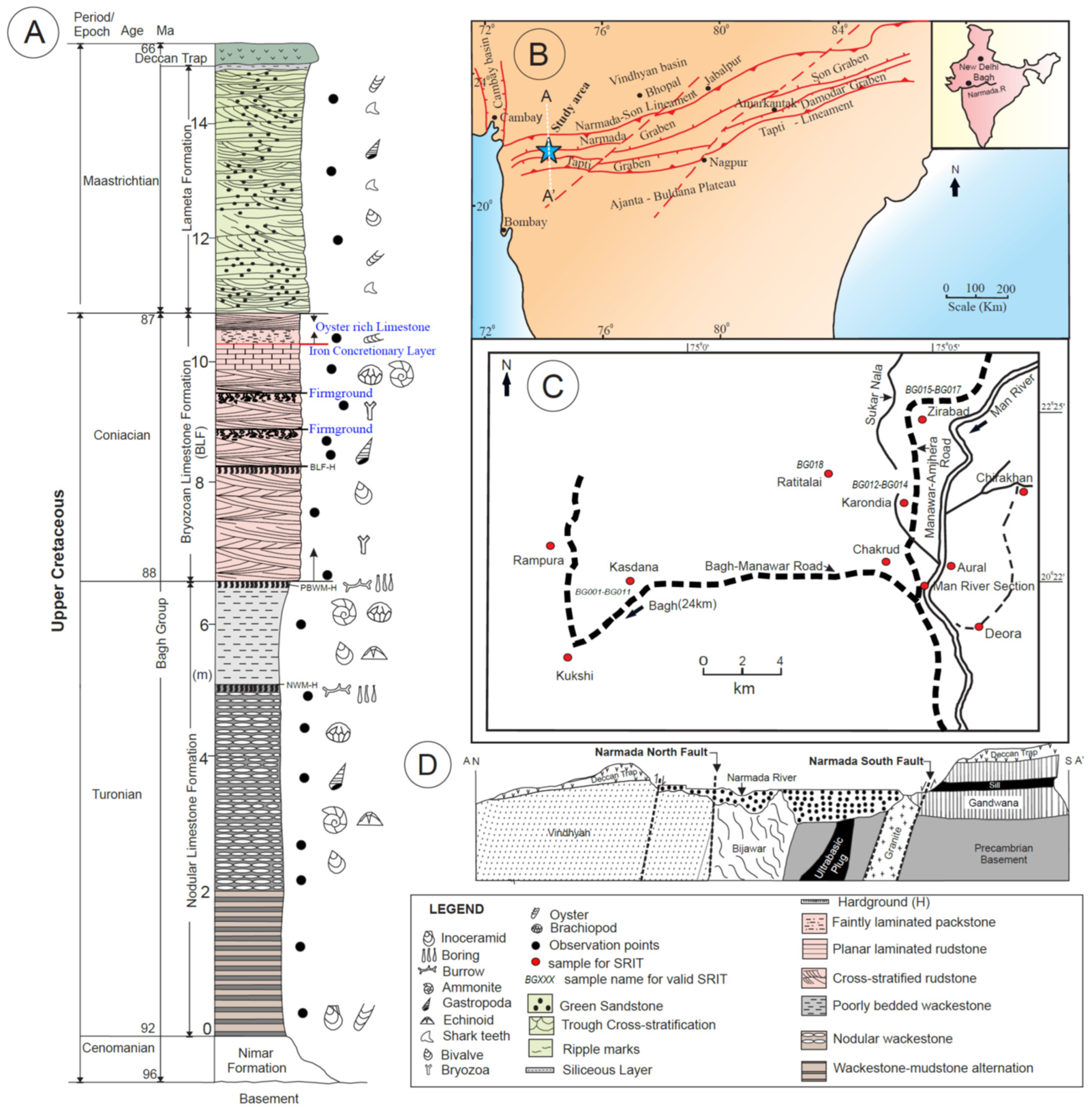
2. Geological Context

The Narmada Graben, situated along the northern flank of the Satpura horst, stands out for its elevated heat flow [28]. This tectonic configuration, with Satpura forming a horst and the adjacent Narmada and Tapi valleys manifesting as grabens (Figure 1B,C), has been substantiated by seismic refraction and wide-angle reflection studies [29]. The bounding faults of the Narmada Graben are steep, dipping at 70–80° (Figure 1D) [30], and show a cumulative displacement of around 1500–1800 m [31].
The carbonate sequence of the Bagh Group of the Narmada Basin in central India represents the epicontinental basin deposits of the Late Cretaceous marine inundation of the Indian subcontinent.

2.1. Lithostratigraphy of the Bagh Group

The Cenomanian fluvio-marine siliciclastic Nimar Formation is overlain by marine carbonates of the Turonian Nodular Limestone Formation and the Coniacian Bryozoan Limestone Formation. At the regional scale, the carbonate deposits are overlain by the Maastrichtian fluvio-marine, siliciclastic Lameta Formation or by flood basalts of the Deccan Traps (Figure 1A), which are absent in the basin but have an estimated thickness of about 1.8 km in the surrounding area [36].

2.2. Facies Constituting the Carbonate of Bagh Group

The Bagh Group comprises several facies described [24] and summarized hereinafter. Nodular Limestone Formation is represented by three non-repetitive facies: (i) Facies A—Wackestone–mudstone alternations, (ii) Facies B—Nodular wackestone, and (iii) Facies C—Poorly bedded wackestone. The overlying Bryozoan Limestone Formation (also known as Coralline Limestone, Barwah Bryozoan Limestone, and Chirakhan Limestone) consists of three facies: (i) Facies D—Cross-stratified rudstone, (ii) Facies E—Planar laminated rudstone, and (iii) Facies F—Faintly laminated packstone in ascending order.
Three distinct hardgrounds are present in ascending stratigraphic order: the first (Hardground 1), a 20 cm thick, brownish to pinkish yellow, extensively burrowed, bored (by Gastrochaenolites and Trypanites), and encrusted surface atop the nodular wackestone of the Nodular Limestone Formation; the second (Hardground 2), a 20 cm thick, rust brown, Fe-oxide impregnated layer at the top of this formation, separating it from the overlying Bryozoan Limestone and exhibiting bored bioclasts (echinoderm and bryozoan remains), Gastrochaenolites burrow erosion, truncation, and encrustation by Chiplonkarina and oysters; and the third (Hardground 3), within the Bryozoan Limestone, atop a cross-stratified Bryozoan Limestone unit, marked by Fe-oxide impregnated Thalassinoides burrows and transitioning upward into firmgrounds. Brief description and process interpretation of these facies are given below.
Wackestone–mudstone alternations: This facies consists of dark gray to pinkish gray colored wackestone–mudstone alternations about 1.7 to 3.1 m thick with parallel to wavy bed geometry, characterized by a lack of primary depositional sedimentary structures and a paucity of fossils with low degree of bioturbation and desiccation cracks. The wackestone beds often contain pisoids, intraclasts, and relics of bioclasts such as gastropods, echinoderms, molluscs, and forams with abundant calcispheres. A low-energy, upper intertidal to supratidal depositional environment that undergoes frequent subaerial exposures.
Nodular wackestone: Varying in thickness from 1.6 m to 2.9 m, this facies consists of nodular wackestone, locally grading to packstone, and is distinguished by desiccation cracks, root structures, a rich assemblage of invertebrate fossils (including bored and fragmented shells), in situ brecciated rootlets, rhizoconcretions with alveolar–septal texture, invertebrate borings, and Thalassinoides burrows. The nodules, primarily composed of lime mudstone and ranging in shape from broadly spherical (3–7 cm diameter) to ellipsoidal, are embedded within a matrix predominantly consisting of micrite rich in well-preserved bioclasts such as gastropods, echinoderms/echinoid spines, and molluscs, reflecting the abundance of micrite and poor sorting of the bioclasts. The low-energy shallow marine platform—tidal flat depositional condition with long periods of subaerial exposure and pedogenesis.
Poorly bedded wackestone: This facies consists of crudely laminated or massive wackestone characterized by distinct flattened nodularity in which nodules are isolated to be jointed and wrapped by thick seams of high proportion of argillaceous material. The thickness of the facies varies from 1.3 m to 2.4 m and exhibits alveolar texture and intensive calcification. Bioclasts, mainly gastropod, bivalve, and rare foraminifera, occur in patches and are frequently impregnated by Fe-oxides. A low-energy environment of deposition, along with pedogenesis during long periods of subaerial exposure.
Cross-stratified rudstone: Reddish brown to whitish-brown, thick- to thin-bedded rudstones, characterized by trough and planar cross-stratification with a weakly bipolar, flood-tide dominated paleocurrent pattern, comprise these facies, which contain fragmented bryozoans, echinoids, brachiopods, bivalves, and gastropods, are well-sorted with no micrite, and are occasionally bioturbated by Thalassinoides. High-energy depositional environment characteristic of the lower intertidal environment.
Planar laminated rudstone: The facies consists of greenish gray, planar laminated rudstone, ranging from 20 cm to 1.3 m thick, characterized by dissolved and strongly bored bioclasts with Fe-oxide coatings and intense micritization; microscopic analysis revealed abundant skeletal grains, including fragments of echinoderms (e.g., echinoid spines), bryozoans, gastropods, ostracods, brachiopods, mollusks, and foraminifera, within a matrix containing moderate amounts of feldspar and quartz, along with 10%–25% glauconite. A high-energy depositional condition of a lower intertidal depositional setting.
Faintly laminated packstone: The facies, ranging from 1 to 1.5 m in thickness, are dominantly composed of poorly bioturbated, fossiliferous packstone with a grain-supported fabric. Well-sorted allochems are a key feature, along with Thalassinoides burrows, abundant meniscus cement, and biomolds. Bioclasts, including bryozoans, echinoderms, and bivalves, make up a significant portion of the rock (up to 80%). Moderate energy depositional conditions in near-shore environments are related to lower intertidal deposits.
A low-energy, restricted, shallow, marine-platform, tidal flat system (ranging from supratidal to upper intertidal), subject to periodic subaerial exposures, is inferred for the deposition of the Nodular Limestone. This environment is suggested by the dominance of fine-grained carbonates and mud, the presence of well-preserved small body fossils, and the overlying carbonate units, which signify a reduction or cessation of clastic input in the post-Nimar transgressive depositional system. On the other hand, the presence of abundant cross-stratified/plane-laminated rudstone with siliciclastics, rare mud content, and well-sorted bioclasts in the Bryozoan Limestone provides strong evidence for a high-energy, shallow marine (lower intertidal channels) depositional environment [24,37,38,39,40]. The presence of three hardgrounds within the carbonate sequence—primarily marking surfaces of non-deposition—and the associated pattern of slow water-level rise (transgressive trend) followed by a sharp drop suggest an asymmetric depositional cycle.

3. Materials and Methods

3.1. Stylolites in the Carbonate of Bagh Group

A series of 30 bedding-parallel stylolites were sampled throughout the rock units in several points of the basin (Figure 1B) for subsequent petrographic investigation, morphology, and roughness characterization.
The carbonate rock of the Bagh Group exhibits a dispersed distribution of stylolites, ranging from microscopic to macroscopic. Three distinct stylolite connectivity types—isolated, long-parallel, and anastomosing networks (Figure 2, Figure 3 and Figure 4) determine the potential for fluid flow in rocks, a parameter influenced by not only stylolite morphology but also wavelength, amplitude, and orientation [9].
Following the classification of [4], we recognized stylolites with diverse morphologies, including seismogram pinning (Class 2) type (Figure 5B), suture and sharp peak (Class 3) type (Figure 5A and Figure 6A,C), and simple wave (Class 4) type (Figure 2C and Figure 6D).

3.2. Methodology for Stress Inversion

Stylolite roughness can be studied as a 2D track on a polished cross-section cut perpendicular to the stylolite’s plane [7] to assess the magnitude of the principal stress striking parallel to the stylolite’s teeth [13]. To achieve this, SRIT [41] consists of performing signal analysis on the roughness, i.e., the difference in height between two consecutive points constitutive of the track can be studied as a signal, with various spatial frequencies corresponding to the horizontal distance between the consecutive points [13].
The method is based on a model where stylolite’s growth is balanced between the two stabilizing forces—one is long-range elastic fluctuation, and the other is local surface tension—and a destabilizing force related to pinning particles [13]. As the main destabilizing force depends on the scale of observation, there is, in the spectral domain, a characteristic length at which the regime developing roughness switches from being controlled by the elastic forces to being controlled by the local surface tension. This length is a key factor named the Crossover Length (Lc), which depends on both mean and differential stress under which the roughness is developed as follows:
L c = γ E β σ m σ d
where Lc is crossover length, E is Young’s Modulus, γ is solid–fluid interfacial energy, and β = υ ( 1 2 υ ) π is a dimensionless constant. υ is Poisson’s ratio and σ d and σ m are differential stress and mean stress, respectively.
In other words, SRIT can return stress magnitude at the time a stylolite stopped developing. In a Fourier domain on a log–log plot (using FPS—Fourier Power Spectrum), both the roughness controlled by elastic and surface energy are defined by a straight line with a different slope [7,13]. This slope is defined by the Hurst Coefficient (H), a transferable coefficient determined for the FPS as a power law exponent of P(k) = k−(1+2H), depending on the origin of the phenomenon it describes, with capillary effects mainly dominant when H > 1(here mainly 1.1) at short length scale whereas H < 1 (Here mainly 0.5) the stress distribution may control the geomorphometry of stylolites during formation at large scale length [7].
When applied to bedding parallel stylolites (BPS), that developed under a maximum principal stress being vertical, it is possible to assume that both horizontal stresses are of the same value (uniaxial strain hypothesis), leading to a simplification of Equation (1) as follows [14]:
L c = γ E β α σ z z 2
where α = 1 1 + υ ( 1 2 υ ) 3 ( 1 υ ) ( 1 υ ) and β = υ ( 1 2 υ ) π .
Then, one can derive the depth z at which the stylolite’s growth stopped by using ρ , the average density of the rock column above the studied strata, and g, the acceleration of gravitational forces, as follows:
σ v = ρ g z
Previous parametric studies suggested that the selection of suture and sharp peak-type stylolites for maximum paleo-depth determination, suture and sharp peak stylolite types (class 3) are optimal, whereas seismogram pinning stylolites (class 2) yield intermediate depth estimations [8,19].

3.3. Applicability to the Bagh Group Formations

Here, we studied nearly 30 BPS (Bedding Parallel Stylolites) collected from hand samples of Bryozoan Limestone from the Bagh Group (Figure 1). Following what was recalled previously, the sampling focused on class 2 (seismogram pinning) and class 3 (suture and sharp peak) stylolites. Selected hand samples were cut perpendicular to the stylolite track, ensuring the peak of the stylolite was locally perpendicular to the dissolution plane in 2D. Cuts were polished to remove the clay from the samples and then scanned using a high-resolution 2D scanner (3200 dpi), corresponding to a pixel size of 8 µm. The track of each stylolite was then digitized by hand using the pencil tool (thickness 5.00) with a 400% magnification in GIMP 2.10.38. We used the Matlab script developed by [14,26], updated by [21,22]. It involves a non-linear regression of fixed slopes (1.1 and 0.5) that enables them to find the slope break (Lc) within 23% uncertainties. According to [20], the propagation of this uncertainty into Equation (2) leads to estimates of σv within 12% uncertainty, providing no major error is made on the other parameters.
Consequently, in order to perform the inversion to stress, we estimated the Young’s modulus (E), which is considered the most uncertain elastic parameter for carbonate rocks [42], using the Schmidt hammer. It is a measure of the rebound value (R) of a spring-loaded piston when applied orthogonally to the rock surface. This R value scales with the Young modulus of the rock, following E = 0.00013 × R3.090704 [43]. Other parameters involved in Equations (2) and (3) are well-constrained in carbonate rocks. Thus, we consider γ = 0.23 J/m2 [44] and Poisson’s ratio υ = 0.25 ± 0.05 [45]. Lastly, we calculate the paleostress burial depth (z) considering the density of potentially overlying rocks ( ρ = 2700 Kg/m3) and g = 9.81 m/s2.

4. Results

Out of the 30 collected samples, 18 BPS returned a valid inversion (Figure 1C), i.e., two slopes well defined by the two Hurst exponents of 1.1 and 0.5 (Figure 7, Table 1). Lc values vary from 0.31–1.26 (Figure 7), with no clear relationship to the relative depth of sampling if considering the Bagh Group. For conducting the inversion from Lc to stress, we assumed the horizontal in-plane stress was negligible. The values for Young’s Modulus, by far the biggest source of uncertainty in SRIT [22,27], were estimated through the rebound value obtained with the Schmidt Hammer. A total of 45 R values were obtained from flat, homogeneous surfaces across 31 samples of Bagh Carbonate rock. These R values are strikingly consistent and range from 21 to 22, resulting in calculated Young’s moduli between 22 and 25 GPa [43].
Solving Equation (3) for each Lc value, we obtain a paleo burial depth varying between 670 and 1320 m with a median value of 970 m, and first and last quartiles of 810 and 1180 m, respectively (rounded to the closest 10 m, excluding the 12% uncertainty, Table 1).

5. Interpretation

The morphological variability of stylolites within sedimentary rocks, characterized by wavelength, frequency, and amplitude across multiple scales, exerts a significant influence on both the efficiency of fluid flow along dissolution planes and the accurate estimation of chemical compaction [4,6]. The morphology of stylolites is controlled by both growth regimes [4] and the distribution of heterogeneity within the host rock [46]. To ensure that the recorded depth through SRIT is consistent, we analysed suture and sharp peak (Class 3) stylolites [4]. In the Late Cretaceous, carbonates of the Bagh Group were initially deposited in the basin due to marine transgression. Subsequently, its properties were altered by bioturbation. As burial progressed (a few hundred meters), overburden pressure increased (σ1 = σv), and pressure solution was initiated, leading to the formation of stylolites. As our dataset suggests, stylolitization was intense up to 1000 m depth, resulting in extensive stylolitization in the lower layers, marked by closely spaced, well-developed stylolites, reflecting significant volume reduction (Figure 8).

6. Discussion

6.1. Burial Depth

Bedding parallel stylolites develop under a vertical principal stress, and stop developing for various reason, including a rise in local fluid pressure [19], decrease in the solubility gradient by clay accumulation [3], deepening of the strata and accommodation of shortening by more efficient dislocation/recrystallisation mechanisms [10], or change in the tectonic stress regime [47]. This case study reconstructed depth ranging from 600 to 1500 m within the 12% uncertainty for the stress calculations [27], and because we do not have an independent estimate of the expected maximum burial depth, it is hard to explain why BPS halted their development. Indeed, the Bagh Group is the last formation before the Deccan Traps were deposited [48]. As a large portion of the related lava was eroded since deposition, we know that the studied area was covered [49], but we do not know what the thickness of this magmatic cover was. Yet, the Bagh Group carbonates’ own thickness does not allow the explanation of the minimal burial depth of 1500 m when BPS stopped developing. On top of it, one can note that the maximum reconstructed depth is not found only at the bottom of the Bagh Group (BG2–4; BG 12–13, Table 1, Figure 1). So, this range of values probably reflects a sequential stop of BPS activity [18] rather than a synchronous stop at the scale of the whole formation [14]. However, the range of depth reconstructed from SRIT is in agreement with the thickness of the Deccan Traps deposited around the basin but likely eroded in the basin, with a present-day thickness of 700 m to 2 km (average 1.8 km, [36]). We then propose that a minimum of 1.3 km of volcanic material was deposited at the scale of the Narmada Basin, on top of the Bagh Group, and developed a dense stylolite network during the catastrophic accumulation of the traps, i.e., likely under 600 Kyr [50]. This is a minimum thickness because BPS could have stopped developing before strata reached the maximum burial depth.

6.2. About the Duration of Stylolite Development

Stylolites are important microstructures that can significantly alter the fluid flow in carbonate reservoirs [12,51]. Hence, understanding the duration of their development is an important yet elusive and challenging problem. In the literature, comparing the result of SRIT to a burial model enable to estimate the time span during which BPS developed, continuously or not: it is about 50 Myr in the Paris Basin [8], about 150 Myr in the Bighorn Basin (USA, [17]), between 10 and 6 Myr in the Umbria Marches [21], and about 20 Myr in the Lower Congo Basin [19,20]. In the Mirabeau Anticline [52], U-Pb radiochronology was used on syn-solution cements located at the tips of different BPS in the same hand sample and results show that these BPS developed at least 20 Myr apart from each other. These durations contrast with the present case study: one can consider the 1.3 km burial depth as a minimum burial depth, because up to 2 km of volcanic material could have been deposited in the area [36]. If meaningful, this difference implies that all the studied stylolites developed before the complete thickness of the traps was deposited. That brings new constraints to the timescale of stylolite development in nature, suggesting that a complete population of stylolites can develop in less than 1 Myr. In other words, in this case, BPS developed at a quasi-instantaneous rate considering the geological timescale. When studying the BPS depth of development in the Western African Margin, the population of BPS studied by [52] with SRIT highlighted a bimodal distribution of the Lc, leading to the observation of a maximum of stylolite developed during a fast burial phase before 95 Ma while the rest of the population developed after 35 Ma, under a gentler burial rate. The authors suggested that a correlation between burial rate and stylolite development could exist. In literature, no data can allow to independently estimate the timespan of BPS development from the burial rate but the present study, then, it is limiting our capacity to validate if there is a positive correlation between the burial rate and the development of a BPS population (i.e., in other studies, the timespan is estimated from the burial curves). The present case study highlights that it might be possible to develop a big network of BPS in a very short timespan and with a very high burial rate (ca. 2.5 km/Myr). This, in our opinion, raises a challenging question to investigate further.

7. Conclusions

The Late Cretaceous carbonate lithologies of the Bagh Group, situated within the Narmada Basin, exhibit a prevalence of bedding-parallel stylolites of variable dimensions. Morphological analysis of the stylolites present in the Bagh Group’s carbonate rocks reveals two most distinct categories: (a) suture and sharp peak type stylolites, and (b) simple wave type stylolites.
The application of roughness inversion methodology to these stylolites enables the estimation of sedimentary stylolite formation depth, thereby facilitating the reconstruction of stratigraphic burial history. The principal vertical stress and corresponding burial depth are determined by utilizing the suture and sharp peak-type stylolites, which are dominant in the carbonate rocks in the Bagh Group.
The application of the FPS methodology to 18 bedding-parallel stylolite datasets derived from the carbonate lithologies resulted in a heterogeneous distribution of inferred burial depths ranging from 670−1320 m, with a median value of 970 m, independently of the stratigraphic position of samples in the Bagh Group. The calculated depths imply reevaluating the burial history of the Narmada Basin, considering the important role of the now eroded Deccan Traps in the area.
Beyond regional implication, this study is the first to rely on BPS SRIT only to reconstruct burial in a basin, and it clearly illustrates that BPS inversion for vertical stress can be used to serve as a gauge for the minimal thickness of eroded formation and can even guide reconstruction of past eruptive events in both intensity and geographical extent.

Author Contributions

The manuscript is a joint effort of D.K.R. and N.E.B. D.K.R., S.T., G.D. and A.M.: “Conceived the study, performed the field work, provided photographs, gathered the data, and prepared the first version of the manuscript”. N.E.B.: “Additionally prepared model, modified figures, and prepared the graphs”. All authors have read and agreed to the published version of the manuscript.

Funding

This research was funded by SERB, Govt of India, Project file number: EEQ/2023/000086.

Data Availability Statement

The original contributions presented in this study are included in the article. Further inquiries can be directed to the corresponding author.

Acknowledgments

The authors are thankful to the editorial board of Minerals and to the three anonymous reviewers. The authors thank Rajesh Dey (Officer in Charge), Abhijit Sarkar, and the Department Colleagues of CGMGC for infrastructure facilities. Finally, appreciation goes to Sanjoy Sengupta, B. C. Roy Engineering College, Durgapur, for facilities allowing the Schmidt hammer test on rock samples.

Conflicts of Interest

The authors declare no conflicts of interest.

References

  1. Stockdale, P.B. Stylolites: Their Nature and Origin; Indiana University Studies: Bloomington, IN, USA, 1922; Volume 9. [Google Scholar]
  2. Railsback, L.B. Lithologic controls on morphology of pressure-dissolution surfaces (stylolites and dissolution seams) in Paleozoic carbonate rocks from the mideastern United States. J. Sediment. Res. 1993, 63, 513–522. [Google Scholar] [CrossRef]
  3. Toussaint, R.; Aharonov, E.; Koehn, D.; Gratier, J.P.; Ebner, M.; Baud, P.; Rolland, A.; Renard, F. Stylolites: A review. J. Struct. Geol. 2018, 114, 163–195. [Google Scholar] [CrossRef]
  4. Koehn, D.; Rood, M.P.; Beaudoin, N.; Chung, P.; Bons, P.D.; Gomez-Rivas, E. A new stylolite classification scheme to estimate compaction and local permeability variations. Sediment. Geol. 2016, 346, 60–71. [Google Scholar] [CrossRef]
  5. Park, W.C.; Schot, E.H. Stylolites; their nature and origin. J. Sediment. Res. 1968, 38, 175–191. [Google Scholar] [CrossRef]
  6. Stockdale, P.B. Stylolites, primary or secondary? J. Sediment. Res. 1943, 13, 3–12. [Google Scholar] [CrossRef]
  7. Renard, F.; Schmittbuhl, J.; Gratier, J.P.; Meakin, P.; Merino, E. Three-dimensional roughness of stylolites in limestones. J. Geophys. Res. Solid Earth 2004, 109, B3. [Google Scholar] [CrossRef]
  8. Beaudoin, N.; Gasparrini, M.; David, M.E.; Lacombe, O.; Koehn, D. Bedding-parallel stylolites as a tool to unravel maximum burial depth in sedimentary basins: Application to Middle Jurassic carbonate reservoirs in the Paris basin, France. GSA Bull. 2019, 131, 1239–1254. [Google Scholar] [CrossRef]
  9. Magni, S.; Martín-Martín, J.D.; Bons, P.D.; Gomez-Rivas, E. Stylolites in Carbonate Rocks: Morphological Variability According to the Host Rock Texture. Minerals 2025, 15, 132. [Google Scholar] [CrossRef]
  10. Gomez-Rivas, E.; Martín-Martín, J.D.; Bons, P.D.; Koehn, D.; Griera, A.; Travé, A.; Llorens, M.G.; Humphrey, E.; Neilson, J. Stylolites and stylolite networks as primary controls on the geometry and distribution of carbonate diagenetic alterations. Mar. Pet. Geol. 2022, 136, 105444. [Google Scholar] [CrossRef]
  11. Heap, M.J.; Baud, P.; Reuschlé, T.; Meredith, P.G. Stylolites in limestones: Barriers to fluid flow? Geology 2014, 42, 51–54. [Google Scholar] [CrossRef]
  12. Heap, M.; Reuschlé, T.; Baud, P.; Renard, F.; Iezzi, G. The permeability of stylolite-bearing limestone. J. Struct. Geol. 2018, 116, 81–93. [Google Scholar] [CrossRef]
  13. Schmittbuhl, J.; Renard, F.; Gratier, J.P.; Toussaint, R. Roughness of stylolites: Implications of 3D high resolution topography measurements. Phys. Rev. Lett. 2004, 93, 238501. [Google Scholar] [CrossRef]
  14. Ebner, M.; Koehn, D.; Toussaint, R.; Renard, F.; Schmittbuhl, J. Stress sensitivity of stylolite morphology. Earth Planet. Sci. Lett. 2009, 277, 394–398. [Google Scholar] [CrossRef]
  15. Rolland, Y.; Perincek, D.; Kaymakci, N.; Sosson, M.; Barrier, E.; Avagyan, A. Evidence for ∼80–75 Ma subduction jump during Anatolide–Tauride–Armenian block accretion and ∼48 Ma Arabia–Eurasia collision in lesser caucasus–East Anatolia. J. Geodyn. 2012, 56, 76–85. [Google Scholar] [CrossRef]
  16. Bertotti, G.; de Graaf, S.; Bisdom, K.; Oskam, B.; Vonhof, H.B.; Bezerra, F.H.; Reijmer, J.J.; Cazarin, C.L. Fracturing and fluid-flow during post-rift subsidence in carbonates of the Jandaíra Formation, Potiguar Basin, NE Brazil. Basin Res. 2017, 29, 836–853. [Google Scholar] [CrossRef]
  17. Beaudoin, N.; Lacombe, O.; Koehn, D.; David, M.E.; Farrell, N.; Healy, D. Vertical stress history and paleoburial in foreland basins unravelled by stylolite roughness paleopiezometry: Insights from bedding-parallel stylolites in the Bighorn Basin, Wyoming, USA. J. Struct. Geol. 2020, 136, 104061. [Google Scholar] [CrossRef]
  18. Beaudoin, N.E.; Koehn, D.; Aharonov, E.; Billi, A.; Daeron, M.; Boyce, A. Reconstruction of the Temperature Conditions of Burial-Related Pressure Solution by Clumped Isotopes Validates the Analysis of Sedimentary Stylolites Roughness as a Reliable Depth Gauge. Minerals 2025, 15, 73. [Google Scholar] [CrossRef]
  19. Bah, B.; Beaudoin, N.E.; Lacombe, O.; Girard, J.P.; Gout, C.; Godeau, N.; Deschamps, P. Multi-proxy reconstruction of the burial history and porosity evolution of the TOCA carbonate formation in the Lower Congo basin (South West Africa). Mar. Pet. Geol. 2023, 148, 106018. [Google Scholar] [CrossRef]
  20. Zeboudj, A.; Bah, B.; Lacombe, O.; Beaudoin, N.E.; Gout, C.; Godeau, N.; Girard, J.P.; Deschamps, P. Depicting past stress history at passive margins: A combination of calcite twinning and stylolite roughness paleopiezometry in supra-salt Sendji deep carbonates, Lower Congo Basin, west Africa. Mar. Pet. Geol. 2023, 152, 106219. [Google Scholar] [CrossRef]
  21. Labeur, A.; Beaudoin, N.E.; Lacombe, O.; Gout, C.; Callot, J.P. Constraining the onset of orogenic contraction in fold-and-thrust belts using sedimentary stylolite populations (Umbria-Marche Apennines, Italy). J. Struct. Geol. 2024, 182, 105098. [Google Scholar] [CrossRef]
  22. Beaudoin, N.; Koehn, D.; Lacombe, O.; Lecouty, A.; Billi, A.; Aharonov, E.; Parlangeau, C. Fingerprinting stress: Stylolite and calcite twinning paleopiezometry revealing the complexity of progressive stress patterns during folding—The case of the Monte Nero anticline in the Apennines, Italy. Tectonics 2016, 35, 1687–1712. [Google Scholar] [CrossRef]
  23. Labeur, A.; Beaudoin, N.E.; Lacombe, O.; Emmanuel, L.; Petracchini, L.; Daëron, M.; Klimowicz, S.; Callot, J.P. Burial-deformation history of folded rocks unraveled by fracture analysis, stylolite paleopiezometry and vein cement geochemistry: A case study in the Cingoli Anticline (Umbria-Marche, Northern Apennines). Geosciences 2021, 11, 135. [Google Scholar] [CrossRef]
  24. Ruidas, D.K.; Pomoni-Papaioannou, F.A.; Banerjee, S.; Gangopadhyay, T.K. Petrographical and geochemical constraints on carbonate diagenesis in an epeiric platform deposit: Late Cretaceous Bagh Group in central India. Carbonates Evaporites 2020, 35, 1–21. [Google Scholar] [CrossRef]
  25. Karcz, Z.; Scholz, C.H. The fractal geometry of some stylolites from the Calcare Massiccio Formation, Italy. J. Struct. Geol. 2003, 25, 1301–1316. [Google Scholar] [CrossRef]
  26. Ebner, M.; Koehn, D.; Toussaint, R.; Renard, F. The influence of rock heterogeneity on the scaling properties of simulated and natural stylolites. J. Struct. Geol. 2009, 31, 72–82. [Google Scholar] [CrossRef]
  27. Rolland, A.; Toussaint, R.; Baud, P.; Conil, N.; Landrein, P. Morphological analysis of stylolites for paleostress estimation in limestones. Int. J. Rock Mech. Min. Sci. 2014, 67, 212–225. [Google Scholar] [CrossRef]
  28. Shanker, R. Thermal and Crustal Structure of “SONATA”. A Zone of Mid Continental Rifting in Indian Shield. J. Geol. Soc. India 1991, 37, 211–220. [Google Scholar] [CrossRef]
  29. Tewari, H.C. A tectonic model of the Narmada region. Curr. Sci. 2001, 80, 873–878. [Google Scholar]
  30. Shanker, R. Neotectonic Activity along the Tapti-Satpura Lineament in Central India. Indian Miner. 1987, 41, 19–30. [Google Scholar]
  31. Mishra, D.C.; Kumar, S.R. Characteristics of faults associated with Narmada–Son lineament and rock types in Jabalpur sector. Curr. Sci. 1998, 75, 308–310. [Google Scholar]
  32. Ruidas, D.K.; Zijlstra, J.J.P. The hardgrounds of the Turonian–Coniacian carbonates of the Bagh Group of central India. J. Earth Syst. Sci. 2023, 132, 27. [Google Scholar] [CrossRef]
  33. Valdiya, K.S.; Sanwal, J. Satpura horst and Narmada–Tapi grabens. In Developments in Earth Surface Processes; Elsevier: Amsterdam, The Netherlands, 2017; Volume 22, pp. 237–247. [Google Scholar]
  34. Murty, T.V.V.G.R.K.; Mishra, S.K. The Narmada-Son lineament and the structure of the Narmada rift system. J. Geol. Soc. India 1981, 22, 112–120. [Google Scholar] [CrossRef]
  35. Valdiya, K.S. Tectonic framework of India: A review and interpretation of recent structural and tectonic studies. Bull. Geophys. Res. 1973, 11, 79–114. [Google Scholar]
  36. Patro, B.P.K.; Sarma, S.V.S. Trap thickness and the subtrappean structures related to mode of eruption in the Deccan Plateau of India: Results from magnetotellurics. Earth Planets Space 2007, 59, 75–81. [Google Scholar] [CrossRef]
  37. Akhtar, K.; Khan, D.A. A tidal island model for carbonate sedimentation: Karondia Limestone of Cretaceous Narmada basin, India. J. Geol. Soc. India 1997, 50, 481–489. [Google Scholar] [CrossRef]
  38. Gangopadhyay, T.K.; Bardhan, S. Dimorphism and a new record of Barroisiceras De Grossouvre (Ammonoidea) from the Coniacian of Bagh, central India. Can. J. Earth Sci. 2000, 37, 1377–1387. [Google Scholar] [CrossRef]
  39. Jaitly, A.K.; Ajane, R. Comments on Placenticeras mintoi (Vredenburg 1906) from the Bagh Beds (Late Cretaceous), Central India with special reference to turonian nodular limestone horizon. J. Geol. Soc. India 2013, 81, 565–574. [Google Scholar] [CrossRef]
  40. Ruidas, D.K.; Paul, S.; Gangopadhyay, T.K. A reappraisal of stratigraphy of Bagh Group of rocks in Dhar District, Madhya Pradesh with an outline of origin of nodularity of Nodular Limestone Formation. J. Geol. Soc. India 2018, 92, 19–26. [Google Scholar] [CrossRef]
  41. Beaudoin, N.; Lacombe, O. Recent and future trends in paleopiezometry in the diagenetic domain: Insights into the tectonic paleostress and burial depth history of fold-and-thrust belts and sedimentary basins. J. Struct. Geol. 2018, 114, 357–365. [Google Scholar] [CrossRef]
  42. Regnet, J.B.; David, C.; Robion, P.; Menéndez, B. Microstructures and physical properties in carbonate rocks: A comprehensive review. Mar. Pet. Geol. 2019, 103, 366–376. [Google Scholar] [CrossRef]
  43. Katz, O.; Reches, Z.E.; Roegiers, J.C. Evaluation of mechanical rock properties using a Schmidt Hammer. Int. J. Rock Mech. Min. Sci. 2000, 37, 723–728. [Google Scholar] [CrossRef]
  44. Wright, K.; Cygan, R.T.; Slater, B. Structure of the (101ī4) surfaces of calcite, dolomite and magnesite under wet and dry conditions. Phys. Chem. Chem. Phys. 2001, 3, 839–844. [Google Scholar] [CrossRef]
  45. Clark, S.P. Handbook of Physical Constants; Geological Society of America: Boulder, CO, USA, 1966. [Google Scholar]
  46. Andrews, L.M.; Railsback, L.B. Controls on stylolite development: Morphologic, lithologic, and temporal evidence from bedding-parallel and transverse stylolites from the US Appalachians. J. Geol. 1997, 105, 59–73. [Google Scholar] [CrossRef]
  47. Lacombe, O.; Beaudoin, N.E.; Hoareau, G.; Labeur, A.; Pecheyran, C.; Callot, J.P. Dating folding beyond folding, from layer-parallel shortening to fold tightening, using mesostructures: Lessons from the Apennines, Pyrenees, and Rocky Mountains. Solid Earth 2021, 12, 2145–2157. [Google Scholar] [CrossRef]
  48. Courtillot, V.; Besse, J.; Vandamme, D.; Montigny, R.; Jaeger, J.J.; Cappetta, H. Deccan flood basalts at the Cretaceous/Tertiary boundary? Earth Planet. Sci. Lett. 1986, 80, 361–374. [Google Scholar] [CrossRef]
  49. Self, S.; Mittal, T.; Dole, G.; Vanderkluysen, L. Toward understanding Deccan volcanism. Annu. Rev. Earth Planet. Sci. 2022, 50, 477–506. [Google Scholar] [CrossRef]
  50. Chenet, A.L.; Fluteau, F.; Courtillot, V.; Gérard, M.; Subbarao, K.V. Determination of rapid Deccan eruptions across the Cretaceous-Tertiary boundary using paleomagnetic secular variation: Results from a 1200-m-thick section in the Mahabaleshwar escarpment. J. Geophys. Res. Solid Earth 2008, 113, B4. [Google Scholar] [CrossRef]
  51. Laronne Ben-Itzhak, L.; Aharonov, Z.E.; Karcz, M.K.; Toussaint, R. Sedimentary Stylolite Networks and Connectivity in Limestone: Large-Scale Field Observations and Implications for Structure Evolution. J. Struct. Geol. 2014, 63, 106–123. [Google Scholar] [CrossRef]
  52. Zeboudj, A.; Lacombe, O.; Beaudoin, N.E.; Callot, J.-P.; Lamarche, J.; Guihou, A.; Hoareau, G. Sequence, Duration, Rate of Deformation and Paleostress Evolution during Fold Development: Insights from Fractures, Calcite Twins and U-Pb Calcite Geochronology in the Mirabeau Anticline (SE France). J. Struct. Geol. 2025, 199, 105460. [Google Scholar] [CrossRef]
Figure 1. (A) Stratigraphic column for Upper Cretaceous Bagh Group and Lameta Formation with macro–micro facies analysis and black circles locating the samples used in this study [24,32]. (B) Tectonic elements around the Narmada basin [33] and asterisks used in this study area. (C) Simplified map locating the samples collected for SRIT (red dots) and reporting names for samples on which SRIT was successful. (D) Simplified cross-section of study area [34,35]. Note that the thickness of the Deccan Trap is unknown.
Minerals 15 00766 g001
Figure 2. Field photographs of large-scale parallel stylolites in the Nodular Limestone Formation exhibiting different morphologies of stylolites. (A,B) Anastomosing stylolite networks. (C) Wave-like stylolites. (D) Long layer parallel stylolites (blue arrows mark the mudstone and yellow arrows mark the wakestone). The yellow arrow points at a long parallel stylolite. Scale: Pen’s length, 13 cm.
Minerals 15 00766 g002
Figure 3. Photomicrographs of large-scale parallel stylolites in the Nodular Limestone Formation exhibiting different morphology of stylolites, showing (A,B) anastomosing wave-like stylolites in wackestones and (C,D) anastomosing wave-like stylolites in mudstones. The yellow arrow points at a long parallel stylolite.
Minerals 15 00766 g003
Figure 4. Interconnected stylolite network from an Upper Cretaceous Bagh Group Limestone quarry near Kasdana. Stylolites based on morphology as proposed by [4], with the close-up cross-section view on the right-hand side and stylolite track drawn for the following: (A) stylolite networks with fracture, (B) anastomosing stylolite networks, and (C) long layer parallel type stylolite. The sketch shows general morphology class characteristics (right-hand side) investigated from the Bryozoan Limestone Formation. Scale: Hammer’s length, 30 cm; lens cover’s length, 4 cm in diameter; clinometer’s length, 7 cm.
Minerals 15 00766 g004
Figure 5. Stylolites based on morphology as proposed by [4], with the close-up cross-section view on the right-hand side and stylolite track drawn for the following: (A) suture and sharp peak type stylolites and (B) seismogram pinning type stylolites. The sketch shows general morphology class characteristics (right-hand side) investigated from the Bryozoan Limestone Formation. Scale: Lens cover’s length, 4 cm in diameter.
Minerals 15 00766 g005
Figure 6. Photomicrographs showing types of stylolite. (A) Suture and sharp peak type in packstones. (B) Rectangular layer type stylolites in rudstones. (C) Suture and sharp peak type in rudstones. (D) Wave-like type in packstones. The yellow arrow points at a long parallel stylolite.
Minerals 15 00766 g006
Figure 7. Selected examples demonstrating stylolite roughness inversion techniques. For each case (top-left to bottom-right): First, stylolite track with estimated minimum dissolution. Next is Fourier Power Spectrum (FPS) analysis, including original and binned data following [14,26]. Finally, FPS binned data with modelled regression line (blue) under the same Hurst constraints, also yielding Lc (green star). Black arrows mark the crossover length.
Minerals 15 00766 g007
Figure 8. Schematic representation of the bedding-parallel stylolite (BPS) growth at different steps of the host rock burial history. The Bagh Group is represented in light green, with burrows, bioturbation, and stylolites. The black color of these objects represents active development, while grey represents that they are not developing anymore. Depths reported are derived from SRIT applied to BPS.
Minerals 15 00766 g008
Table 1. Results from the application of the stylolite roughness inversion technique (SRIT) on samples of the Bagh Group, Narmada Basin, India. * FPS (Fourier Power Spectrum) inversion results using γ = 0.23 J/m2 [44], Poisson’s ratio υ = 0.25 ± 0.05 [45], E (Young’s Modulus) = 25 GPa, (density) of rock ρ = 2700 Kg/m3, g = 9.81 m/s2. All stress and depth values are given without the 12% uncertainty, while Lc values are reported without the 23% uncertainty.
Sample No.LocationLat (°N) and Long (°E)Morphology ClassStylolite Length (mm)Crossover Length Lc (mm)Paleostress * (MPa)Depth * (m)
BG001Kasdana22.24 and 74.933200.57226910
BG002Kasdana22.24 and 74.933180.41311090
BG003Kasdana22.24 and 74.933180.32351230
BG004Kasdana22.24 and 74.933150.34341200
BG005Kasdana22.24 and 74.933250.74823810
BG006Kasdana22.24 and 74.933160.59626910
BG007Kasdana22.24 and 74.933201.22518630
BG008Kasdana22.24 and 74.933200.86421740
BG009Kasdana22.24 and 74.932250.60925880
BG010Kasdana22.24 and 74.933250.8921740
BG011Kasdana22.24 and 74.933140.57226910
BG012Karondia22.38 and 74.073140.34341200
BG013Karondia22.38 and 74.073160.39321120
BG014Karondia22.38 and 74.073180.472291020
BG015Zirabad22.41 and 75.072181.2718630
BG016Zirabad22.41 and 75.073200.47291020
BG017Zirabad22.41 and 75.073180.6924840
BG018Ratitalai22.40 and 75.053300.83022770
Disclaimer/Publisher’s Note: The statements, opinions and data contained in all publications are solely those of the individual author(s) and contributor(s) and not of MDPI and/or the editor(s). MDPI and/or the editor(s) disclaim responsibility for any injury to people or property resulting from any ideas, methods, instructions or products referred to in the content.

