

State-of-the-Art Lithium-Ion Battery Pretreatment Methods for the Recovery of Critical Metals

Abstract
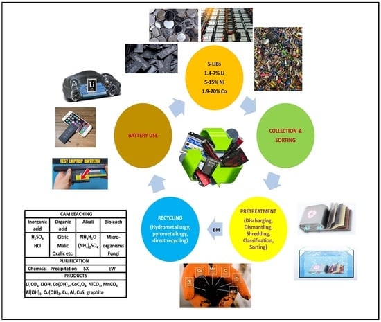
1. Introduction
1.1. Using Batteries as a Symbol of Sustainable Development
1.2. Lithium-Ion Batteries (LIBs) and Their Overall Performance
1.3. The Need to Recycle LIBs
1.4. The Global Market of LIBs and the Need to Supply Raw Materials for Batteries
1.5. The Most Important Limitations of the Research: Challenges and Obstacles in Previous Studies
2. LIB Components and Their Functions
2.1. Different Components of Lithium-Ion Batteries
- ➢
- Anode (Negative electrode): This includes anode active materials (generally hexagonal layered natural or synthetic graphite) that are placed on the Cu current collector foil [18,25]. Li4Ti5O12, Si, Ge, Sn, and LiO2 (amorphous) were also tested as anode materials. Anodes store and release Li-ions from the cathode, allowing for the passing of the current through an external circuit;
- ➢
- ➢
- Separators: They act like a fuse and also prevent the free movement of electrons in the cell. Separators prevent contact between the anode and cathode. They are generally made of polypropylene (PP) and polyethylene (PE) [18,19,26]. The separator pore diameter is about 0.60 nm, and the thickness is 20–30 µm;
- ➢
- ➢
- ➢
- Conduction enhancers: Carbon black is generally used for increasing the conductance between active materials;
- ➢
- Protective shells and covers (Fe/steel, Al, and plastic, etc.).
2.2. How Do Lithium-Ion Batteries Work?
2.2.1. Cathode (Positive Electrode)
2.2.2. Anode (Negative Electrode)
2.2.3. Separator
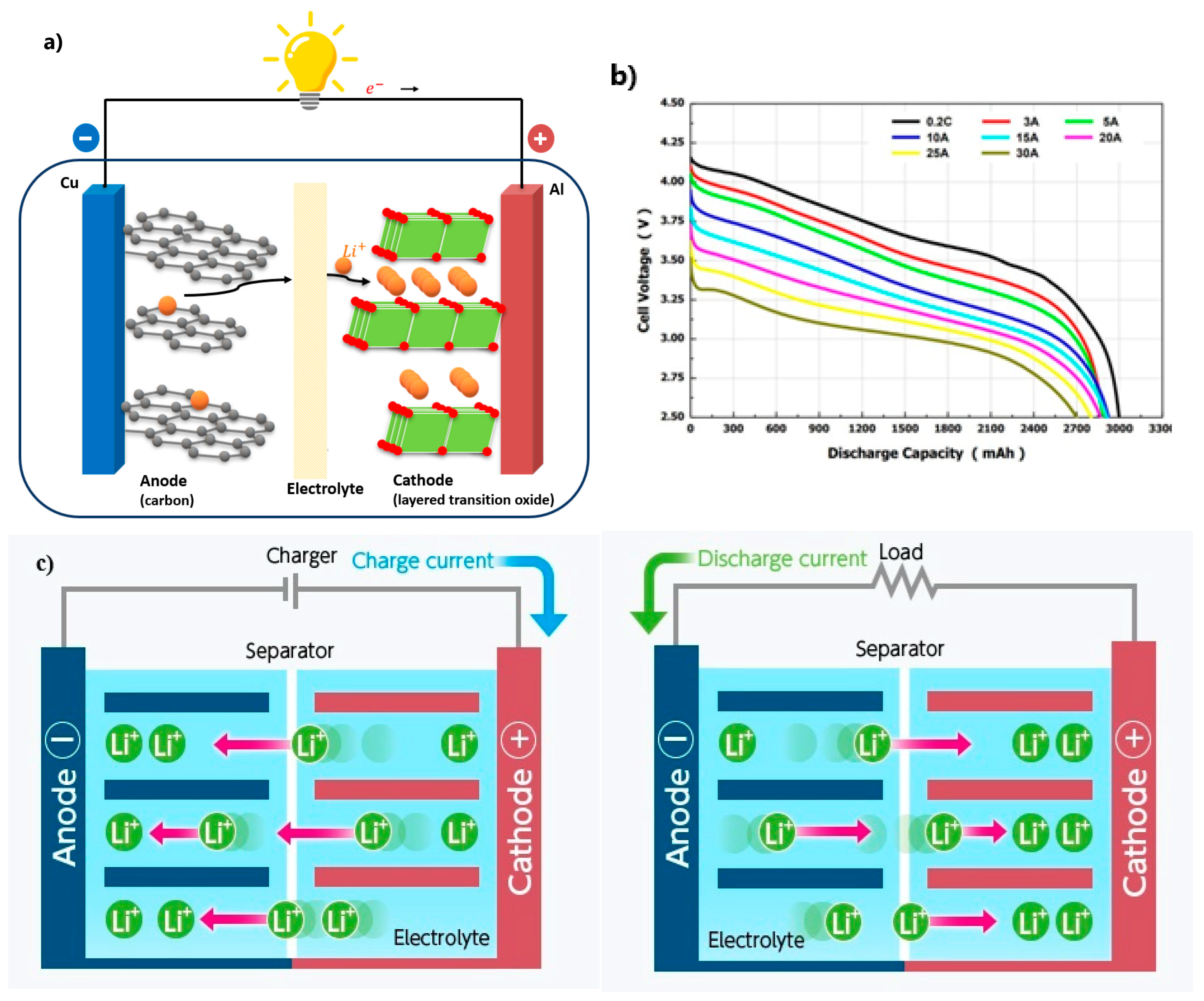
2.2.4. Electrolyte
2.3. Shapes of LIBs
2.4. LIBs’ Improvements in the Future
- Production cost reduction (Now: 130 USD/kWh for cell and 280 USD/kWh for pack; future: 50 USD/kWh for cell and 100 USD/kWh for pack);
- Energy density increase (Now: 700 Wh/L and 250 Wh/kg for cell; future: 1400 Wh/L and 500 Wh/kg for cell), which determines the range of EV;
- Power density increase (Now: 3 kW/Kg for pack; future: 12 kW/kg for pack), which determines the acceleration of EV;
- Safety (future elimination of thermal runaway at pack level to reduce pack complexity);
- First life (Now: 8 years for pack; future: 15 years for pack);
- Temperature range (Now: −20 °C to +60 °C for cell; future: −40 °C to +80 °C for cell);
- Predictivity (future full predictive models for performance and aging of battery);
- Recyclability (Now: 10%–15% for pack; future: 95% for pack);
- Self-healing mechanism of battery electrodes via polymer coating to prevent cracks and battery damage;
- There will be a global LIB recycling race.
2.5. Why Is LIB Processing Challenging?
3. Method
3.1. Previous Classification Studies for Pretreatment
3.2. Important Aspects of Methodology, Including Methods of Data Collection and Analysis
- The pretreatment stage.
- The stage of the battery’s active materials’ separation and purification.
4. Results and Discussion
- Collecting;
- Sorting;
- Deactivation or discharging;
- Disassembly;
- Separating the electrolyte solution;
- Comminution;
- Particle size classification;
- Separation of AAMs and CAMs from current collectors;
- Screening;
- Separation of AAMs and CAMs from each other;
- Other steps include various other creative methods for pretreatment such as drying, heating, ultrasonic vibration, washing, and flotation-based separations.
4.1. Collecting
- Small-scale electrical equipment (SSEE) (household scale): This type of battery is used for portable/consumer electronic devices, has a lifespan of 3–10 years, and can be collected in places established by manufacturers and retailers;
- Stationary energy storage (SES): Fixed grid storage is used for energy storage systems. To collect these types of batteries, specialized and trained personnel are needed to dismantle them from the equipment before collection;
- EVs: Transportation devices such as cars, tracks, e-bikes, and aircraft, etc., use this type of battery. The lifespan of electric cars depends on many factors such as the charging frequency and condition, annual mileage, and battery type, and is considered to be about 8–10 years and 10–12 years considering the second life.
4.2. Sorting
- Sorting batteries based on their type and shape: Sorting batteries by size and shape can be performed due to size limitations in the processing equipment, for example, furnaces [23];
- Sorting batteries according to their size [50];
- Sorting batteries according to their state of health (SoH): Battery sorting can also be carried out based on their SoH. In this method, before deactivating the battery, information about the LIB current range, residual voltage, capacitance, and state of charge (SoC) should be known to establish a safe deactivation process [23];
- LIB sorting can be carried out in two general ways.
4.2.1. Manual Sorting
4.2.2. Automatic Sorting
4.3. Deactivation or Discharging
4.3.1. Why Should LIBs Be Discharged?
- In 2011, the batteries of Chevrolet plug-in hybrids caught fire after a crash test;
- In 2013, the battery of a Tesla Model S electric car caught fire due to an accident;
- In 2016, cases of exploding batteries were reported in Samsung Galaxy Note 7 smartphones;
- In 2018, the luggage rack on a China Southern Airlines flight caught fire due to the explosion of LIBs in a power bank.
- Possible risk of self-ignition.
- Short circuiting.
4.3.2. The Types of Battery Discharge Methods
4.3.3. Battery Discharge via Short Circuit
4.3.4. Battery Discharge Using Solid Conductors
4.3.5. Discharging the Battery Electrically Using Dynamic Resistance
4.3.6. Electric Discharge Through Inductive Effect
4.3.7. Battery Discharge Using Aqueous Solutions
- Salt conductive solutions;
- Acid conductive solutions;
- Alkaline conductive solutions.
Discharge in Salt Solution
↓ ↓
Fe(OH)2(s) Fe(OH)3 (s)
Discharge in Acidic and Alkaline Solutions or Organic Solvents
4.3.8. Battery Discharge via Cryogenic Method
4.3.9. Battery Discharge via Thermal Method
4.3.10. Water Pretreatment
4.4. Corrosion of Batteries During Discharge in Solutions
4.5. Reliable Voltage
4.6. Return Voltage
4.7. Analysis of S-LIBs When They Are Disassembled Without Proper Discharge Operations
- The first reason: During the long-term battery cycle, the anode is prone to the formation of Li dendrites, so this part of Li can hardly be transferred to the cathode during discharge.
- The second reason: The remaining electrolyte is lithium hexafluorophosphate (LiPF6), which is formed on the surface of the anode [67].
4.8. Some Innovations in Discharging Batteries
- MnSO4, Na2SO4, and Na2CO3 solutions do not have the necessary effect in discharging batteries;
- The 1.0 M NaCl solution shows an acceptable amount of discharge after about 5 h. But the NaCl solution causes corrosive damage in S-LIBs and produces large amounts of liquid waste and solid deposits;
- Flaky graphite resulted in zero emissions in the battery discharge process. According to the discharge process of batteries, the flaky graphite discharge method was suggested as one of the most effective and compatible discharge methods for S-LIBs [75].
- The model fast discharges to 1.0 V voltage, which takes the least time to maintain the relative safety of the LIB for the isolation process.
- Full discharge model, which is for discharging LIBs to less than 0.5 V, which releases almost all the residual voltage.
- The battery moves slowly with the conveyor belt and is immersed in the discharge solution inside the discharge device. (The speed of the conveyor belt allows each battery to remain in the solution for 125 min);
- A sediment catcher moves opposite to the batteries and pushes the sediment into the collecting funnel on the left;
- As the composition of the drain solution changes during the draining process, the device is drained through the drain outlet and refilled regularly through the water inlet;
- When the battery leaves the discharge solution, it enters the drip zone. In the drip zone, the solution on the surface of the battery can flow down through the holes in the belt;
- The air flows into the gap between the conveyor and the discharge device and forms a stable air flow [53];
- Then, the battery is dried through a process;
- The toxic gas is removed from the exhaust device by the gas collection hood.
- The following results are reported:
- Compared to the full discharge model, the quick discharge model is easier to use and less expensive because there is only one discharge device and no gas purification is required;
- Although physical methods have high discharge efficiency, they are not stable enough for large-scale plant applications;
- The active discharge time at 0.8 mol/L is 5 min for FeSO4 and 30 min for NaCl, but the final voltage of FeSO4 is slightly greater than that of NaCl [53];
- The 0.8 M NaCl solution and 0.8 mole/L FeSO4 solution are the best chemical discharge solutions;
- The FeSO4 solution was more environmentally friendly compared to the NaCl solution because of corrosion and leakage problems;
- The fast model reduces the residual voltage to 1.0 V in 125 min, and the full model reduces the residual voltage to 0.5 V in 183 min [53].
4.9. Disassembly
4.9.1. Manual Disassembly
- Metal/plastic cover of the battery;
- The anode, including anode active materials (AAM) along with a Cu current collector;
- The cathode, including cathode active material (CAM) along with an Al current collector;
- Other parts of the battery, including the separator and electrolyte, etc.
- The manual disassembly method of batteries has some advantages and disadvantages:
- The removal of plastics and extra materials.
- Increasing the efficiency of the purification department.
- Disadvantages:
- Low efficiency;
- Low safety of the work environment, especially for employees, and the need to use personal protective equipment (PPE);
- The need for a lot of manpower;
- High cost, especially in areas with high manpower costs.
4.9.2. Semi-Automated Disassembly
4.9.3. Automated Disassembly
4.9.4. Some Innovations in Disassembly
4.10. Separating the Electrolyte Solution
4.10.1. Solvent Extraction (SX)
4.10.2. Supercritical CO2 Extraction
- First, CO2 enters the supercritical state by modifying its temperature and pressure in the supercritical reactor [80];
- The electrolyte of the LIB is dissolved in the supercritical fluid;
- Lastly, depressurization is used to separate the electrolyte and CO2;
- Water and HF are removed from the waste electrolyte using weak alkaline anion exchange resins and molecular sieves to utilize recycled goods.
4.10.3. Low-Temperature Volatilization (LTV)
4.11. Comminution
- Next separation stages and selective liberation of CAMs.
- Size reduction is carried out using a series of techniques.
4.11.1. Shredding
4.11.2. Milling
4.11.3. High-Shear Mixing
4.12. Wet and Dry Grinding
4.12.1. Wet Grinding
4.12.2. Dry Grinding
- The crushing is performed in an inert atmosphere of nitrogen;
- The first step of crushing is conducted with a low-speed rotary crusher;
- The second crushing is accomplished with a high-speed impact crusher;
- The hammer crushing, coupled with a two-blade rotor crusher, maximized the recovery of the black mass.
4.13. Some Innovations in the Crushing of S-LIBs Without Discharge
- A significant amount of nitrogen gas in the shredding chamber can slow down the rate of exothermic chemical reactions among shredded LIBs;
- The rapid movements between the crushed LIBs and the nitrogen gas cause the heat generated during comminution to dissipate quickly;
- The contact between the anode plates and the cathode plates is continuously reduced due to the rapid rotation of the rotor and N2, which is useful for reducing the short circuit between them, resulting in less heat generation;
- Finally, the electrolyte pump causes the electrolytes produced during crushing to quickly leave the crushing chamber, which can reduce the chemical reactions on the electrolytes. They showed that the lower and upper valves, the inlet nitrogen gases, and the other repairs made to the crusher ensure that the crushing of S-LIBs is safe and clean. In this method, dangerous substances can be purified via an evaporation process at low temperatures. One of the features of this method is the possibility of using it in industry [1].
4.14. Physical Separation Methods
4.14.1. Particle Size Classification/Separation (Sieving)
4.14.2. Magnetic Separation
4.14.3. Density and Pneumatic Separation
4.14.4. Electrostatic Separation
4.14.5. Eddy Current Separation
4.14.6. Gravity Separation
4.15. Separation of Cathode and Anode Active Materials from Current Collectors
4.16. Separation of Anode Active Materials (AAM) from Anode Current Collector (Cu)
4.17. Separation of Cathode Active Materials (CAMs) from the Current Collector in the Cathode (Al)
- Mechanical separation;
- Thermal and chemical deactivation treatment methods;
- Mechanochemical methods.
4.17.1. Mechanical Separation
- Pyrolysis of cathodes at 500 °C for 90 min and using the air jet impact process for 1 min to recover the coating powders with low organic contents [59].
4.17.2. Methods Based on Thermal and Chemical Treatment
4.17.3. Mechanochemical Methods
4.18. Some Innovations in the Separation of AAMs and CAMs from Current Collectors
4.19. Screening
- More than 90% of valuable metals (Li, Ni, Co, and even C) accumulate at the 212 µm size.
- However, more than 80% of the weight of Cu and Al in the battery is placed in the coarse size category above 1.4 mm.
4.20. Separation of AAMs and CAMs from Each Other
- Fine bubbles are introduced into the flotation cell containing the material for separation;
- Frothers stabilize the bubbles (i.e., aromatic alcohols and cyclic carbonates);
- Hydrophobic graphite is collected by the bubbles, transferred to the surface, and remains in a stable froth on the surface;
- Hydrophobic graphite components are recovered as a floating product, while hydrophilic CAM particles sink and are collected from tailing.
- The brittleness of the PVDF binder and the increased possibility of breaking it during the crushing stage can cause a better separation between the active materials of the cathode and the adhesive;
- Also, to maximize the separation using froth flotation, which takes advantage of the difference in the hydrophobicity of materials, surface modification through binder decomposition or surface treatment should be used to effectively improve the selection of froth flotation [59];
- To prevent the emission of toxic HF and P2O5 during the removal of the organic layer through heat treatment, Fenton’s reagent (Fe2+ + H2O2) can be used to oxidize and remove the layer, but more research is needed to remove Fe-containing impurities.
4.21. Other Steps, Such as a Variety of Other Creative Methods for Pretreatment
4.22. Suggested Flowsheets Related to Pretreatment in the Recovery of Critical Metals from LIBs
4.23. Metallurgical Steps
- Pyrometallurgical and hydrometallurgical methods;
- Hydrometallurgical method;
- Direct recycling method;
- Biometallurgical method;
- Mechanochemical method;
- Combined methods.
- Operational simplicity and flexibility: Pyrometallurgical methods can treat mixed battery chemistries and formats with minimal pretreatment, which is highly beneficial for large-scale processing without prior sorting or disassembly;
- Established infrastructure: Existing smelting plants, especially in the Cu and Ni sectors, can accommodate battery black mass with relatively low capital investment costs, and leveraging decades of metallurgical experience;
- Large processing capacity: These processes are suitable for continuous operation and high-throughput industrial-scale systems, making them attractive in regions with large volumes of battery waste.
4.24. An Overview of the Latest Advances in the Pretreatment of LIBs on an Industrial Scale
4.25. Recycling Batteries Is a Way to Reduce the Lack of Metal Resources
4.26. Issues with Existing LIB Recycling Technologies
4.27. Directions for Future Research in LIBs
5. Summary and Conclusions
- The development of new methods for separating cathodes from Al foil: Investigating and developing new mechanical, chemical, and physical methods for the more effective separation of cathodes from Al foil can help to improve the pretreatment process;
- Investigating the environmental effects of pretreatment processes: Comprehensive studies on the environmental effects (such as emissions and waste byproducts) of different pretreatment methods and evaluating the advantages and disadvantages of each in terms of environmental sustainability;
- Use of artificial intelligence and machine learning technologies: Development of artificial intelligence and machine learning models to optimize pretreatment processes and predict recycling results;
- Increasing international cooperation to share knowledge and experiences and develop global standards between research centers and recycling industries in the field of LIB recycling;
- The development of new and less expensive methods with improved energy efficiency for improving economic and environmental aspects: The high cost of recycling LIBs is currently one of the major obstacles in the way of the industrialization of most current methods. Research on novel and less expensive methods for recycling valuable materials from used batteries, such as the use of biotechnology, nanotechnology, and ultrasonic delamination, can greatly help the battery recycling industry to expand;
- The optimization of pretreatment processes to reduce energy consumption and increase efficiency in different stages of recycling using green energy sources;
- Safety management: Developing safer methods to manage and recycle spent batteries to avoid potential hazards such as fire and chemical spills;
- Automatic methods: Research on and the development of automatic and intelligent systems for separating and recycling batteries to increase accuracy, which is around 23%, and reduce human costs;
- Economic models: The development and evaluation of new economic models for recycling batteries that bring economic improvement and investment attractiveness in this field;
- Social studies: Examining consumer attitudes and behaviors and social and cultural impacts related to battery recycling;
- Pilot projects: The implementation of large-scale pilot projects to evaluate the practicality of and identify possible challenges in the recycling process of S-LIBs. These suggestions can be used as a roadmap for future research in the field of the pretreatment and recycling of S-LIBs and help to improve processes and reduce environmental impacts;
- The environmental footprint of battery production is quite high. One ton of Li (enough for about 100 car batteries) requires about 2 million tons of water, which makes LIB production an extremely water-intensive process. The use and discharge of chemicals during the mining and extraction of metals are huge, and a tremendous amount of energy is consumed [125].
Author Contributions
Funding
Data Availability Statement
Conflicts of Interest
Abbreviations
| AAM | Anode active material | LTO | Li4Ti5O12 |
| AC | Alternative current | LTV | Low-temperature volatilization |
| Al | Aluminum | M | Million |
| ANVIIL | Incineration and impact liberation | Mn | Manganese |
| BM | Black mass | MJ | Mega Joule |
| BMS | Battery management system | N2 | Nitrogen gas |
| C | Carbon | NCA | LiNi0.8Co0.15Al0.05O2 |
| CAGR | Compound annual growth rate | NIR | Near-infrared |
| CAM | Cathode active material | NMC | LiNi1-x-yMnxCoyO2 |
| Cl2 | Chloride gas | NMP | N methyl-2-pyrrolidone |
| CMC | Carboxymethylcellulose | NCA | LiNi0.8Co0.15Al0.05O2 |
| CRM | Critical raw materials | MJ | Mega Joule |
| Co | Cobalt | N2 | Nitrogen gas |
| Cu | Copper | Ni | Nickel |
| C2C | Cradle-to-cradle | NMC | LiNi1-x-yMnxCoyO2 |
| CUAWL | Carbonated ultrasound-assisted water leaching | NMP | N methyl-2-pyrrolidone |
| CS | Central server | OCV | Open circuit voltage |
| DC | Direct current | PC | Propylene carbonate |
| DEC | Diethyl carbonate | PE | Polyethylene |
| DMC | Dimethyl carbonate | PP | Polypropylene |
| DMF | N, N dimethylformamide | PSD | Particle size distribution |
| DMAC | N, N dimethylacetamide | PTFE | Polytetrafluoroethylene |
| DMSO | Dimethyl sulfoxide | PVDF | Polyvinylidene fluoride |
| EDTA | Ethylenediaminetetraacetic acid | RFID | Radiofrequency identification |
| EoL | End-of-life | QR | Quick response |
| ESS | Energy storage system | SBR | Styrene-butadiene rubber |
| EU | European Union | SDG | Sustainable development goal |
| EV | Electrical vehicle | SES | Stationary energy storage |
| Fe | Iron | SEI | Solid electrolyte interface |
| GIC | Graphite intercalating compound | S/L | Solid/liquid ratio |
| GIS | Geographic information system | S-LIB | Spent lithium-ion batteries |
| GPRS | General packet radio service | SoC | State of charge |
| IEC | Internal combustion engine | SOH | State of health |
| IL | Ionic liquid | SSEE | Small-scale electrical equipment |
| IoT | Internet of Things | SX | Solvent extraction |
| Li | Lithium | TFA | Trifluoroacetic acid |
| LCO | LiCoO2 | TOC | Total organic carbon |
| LIB | Lithium-ion battery | US | United States |
| LIBRA | LIB resource assessment | XPS | X-ray photoelectron spectroscopy |
| LFP | LiFePO4 | XRD | X-ray diffraction |
| LMP | LiMnPO4 | VO | Vanadium oxide |
| LMO | LiMn2O4 | VOC | Volatile organic compound |
| LMNO | LiMnNiO4 | VTR | Vacuum thermal recycling |
| LNO | LiNiO2 |
References
- Zhong, X.; Liu, W.; Han, J.; Jiao, F.; Qin, W.; Liu, T. Pretreatment for the recovery of spent lithium-ion batteries: Theoretical and practical aspects. J. Clean. Prod. 2020, 263, 121439. [Google Scholar] [CrossRef]
- Ren, Z.; Li, H.; Wang, Y.; Zhang, G.; Wang, P.; Lv, L.; Sun, Z.; Gao, W. Green recycling assessment on typical spent lithium-ion batteries (LIBs): A multi-objective assessment. Resour. Conserv. Recycl. 2024, 206, 107648. [Google Scholar] [CrossRef]
- Premathilake, D.S.; Botelho Junior, A.B.; Tenório, J.A.S.; Espinosa, D.C.R.; Vaccari, M. Designing of a decentralized pretreatment line for EOL-LIBs based on recent literature of lib recycling for black mass. Metals 2023, 13, 374. [Google Scholar] [CrossRef]
- Han, Y.; Chen, J.; Li, H.; Deng, Y. Comprehensive recovery process of impurities removal and valuable metals co-extraction from simulated leaching solution of spent LIBs with CA12-TBP system. Sep. Purif. Technol. 2023, 326, 124773. [Google Scholar] [CrossRef]
- Christensen, P.A.; Anderson, P.A.; Harper, G.D.; Lambert, S.M.; Mrozik, W.; Rajaeifar, M.A.; Wise, M.S.; Heidrich, O. Risk management over the life cycle of lithium-ion batteries in electric vehicles. Renew. Sustain. Energy Rev. 2021, 148, 111240. [Google Scholar] [CrossRef]
- Weigl, D.; Young, D. Impact of automated battery sorting for mineral recovery from lithium-ion battery recycling in the United States. Resour. Conserv. Recycl. 2023, 192, 106936. [Google Scholar] [CrossRef]
- Shi, P.; Yang, S.; Wu, G.; Chen, H.; Chang, D.; Jie, Y.; Fang, G.; Mo, C.; Chen, Y. Efficient separation and recovery of lithium and manganese from spent lithium-ion batteries powder leaching solution. Sep. Purif. Technol. 2023, 309, 123063. [Google Scholar] [CrossRef]
- Kaya, M. Anatomy, Invited Speaker. In Proceedings of the 18th International Mineral Processing Symposium (IMPS-2024), Eskişehir, Turkey, 16–18 December 2024. [Google Scholar]
- Kaya, M. State-of-the-art lithium-ion battery recycling technologies. Circ. Econ. 2022, 1, 100015. [Google Scholar] [CrossRef]
- Yang, T.; Luo, D.; Liu, Y.; Yu, A.; Chen, Z. Anode-free sodium metal batteries as rising stars for lithium-ion alternatives. iScience 2023, 26, 105982. [Google Scholar] [CrossRef]
- Bae, H.; Kim, Y. Technologies of lithium recycling from waste lithium-ion batteries: A review. Mater. Adv. 2021, 2, 3234–3250. [Google Scholar] [CrossRef]
- Yu, W.; Guo, Y.; Xu, S.; Yang, Y.; Zhao, Y.; Zhang, J. Comprehensive recycling of lithium-ion batteries: Fundamentals, pretreatment, and perspectives. Energy Storage Mater. 2023, 54, 172–220. [Google Scholar] [CrossRef]
- Domingues, A.M.; de Souza, R.G. Review of life cycle assessment on lithium-ion batteries (LIBs) recycling. Next Sustain. 2024, 3, 100032. [Google Scholar] [CrossRef]
- Wei, N.; He, Y.; Zhang, G.; Feng, Y.; Li, J.; Liu, Z.; Ding, L.; Xie, W. Green recycling of valuable metals from spent cathode materials by water electrolysis. J. Environ. Chem. Eng. 2023, 11, 111150. [Google Scholar] [CrossRef]
- Liu, M.; Liu, W.; Liu, W.; Chen, Z.; Cui, Z. To what extent can recycling batteries help alleviate metal supply shortages and environmental pressures in China? Sustain. Prod. Consum. 2023, 36, 139–147. [Google Scholar] [CrossRef]
- Kim, S.; Bang, J.; Yoo, J.; Shin, Y.; Bae, J.; Jeong, J.; Kim, K.; Dong, P.; Kwon, K. A comprehensive review on the pretreatment process in lithium-ion battery recycling. J. Clean. Prod. 2021, 294, 126329. [Google Scholar] [CrossRef]
- Zheng, X.; Zhu, Z.; Lin, X.; Zhang, Y.; He, Y.; Cao, H.; Sun, Z. A mini-review on metal recycling from spent lithium-ion batteries. Engineering 2018, 4, 361–370. [Google Scholar] [CrossRef]
- Kaya, M. Recovery of Lithium from Secondary Resources: Recycling Technologies of Spent Lithium-Ion Batteries; CRC Press: Boca Raton, FL, USA, 2024. [Google Scholar] [CrossRef]
- Chen, Q.; Hou, Y.; Lai, X.; Shen, K.; Gu, H.; Wang, Y.; Guo, Y.; Lu, L.; Han, X.; Zheng, Y. Evaluating environmental impacts of different hydrometallurgical recycling technologies of the retired nickel-manganese-cobalt batteries from electric vehicles in China. Sep. Purif. Technol. 2023, 311, 123277. [Google Scholar] [CrossRef]
- Wang, H.; Huang, Y.; Huang, C.; Wang, X.; Wang, K.; Chen, H.; Liu, S.; Wu, Y.; Xu, K.; Li, W. Reclaiming graphite from spent lithium-ion batteries ecologically and economically. Electrochim. Acta 2019, 313, 423–431. [Google Scholar] [CrossRef]
- An, B.-H.; Lee, T.-G.; Khan, T.T.; Seo, H.-W.; Hwang, H.J.; Jun, Y.-S. Optical and quantitative detection of cobalt ions using graphitic carbon nitride-based chemosensor for hydrometallurgy of waste lithium-ion batteries. Chemosphere 2023, 315, 137789. [Google Scholar] [CrossRef]
- Wei, Q.; Wu, Y.; Li, S.; Chen, R.; Ding, J.; Zhang, C. Spent lithium-ion battery (LIB) recycle from electric vehicles: A mini-review. Sci. Total Environ. 2023, 866, 161380. [Google Scholar] [CrossRef]
- Yu, D.; Huang, Z.; Makuza, B.; Guo, X.; Tian, Q. Pretreatment options for the recycling of spent lithium-ion batteries: A comprehensive review. Miner. Eng. 2021, 173, 107218. [Google Scholar] [CrossRef]
- Zhou, A.; Liu, Z.; Liu, Z. Efficient separation of Li and Mn from spent LiMn2O4 cathode materials by NH4HSO4 reduction roasting-selective ammonia leaching. Sep. Purif. Technol. 2024, 332, 125561. [Google Scholar] [CrossRef]
- Nazari, P.; Hamidi, A.; Golmohammadzadeh, R.; Rashchi, F.; Vahidi, E. Upcycling spent graphite in LIBs into battery-grade graphene: Managing the produced waste and environmental impacts analysis. Waste Manag. 2024, 174, 140–152. [Google Scholar] [CrossRef]
- Dai, Q.; Spangenberger, J.; Ahmed, S.; Gaines, L.; Kelly, J.C.; Wang, M. Everbatt: A Closed-Loop Battery Recycling Cost and Environmental Impacts Model; Argonne National Lab. (ANL): Lemont, IL, USA, 2019. [Google Scholar]
- Khodadadmahmoudi, G.; Javdan Tabar, K.; Homayouni, A.H.; Chehreh Chelgani, S. Recycling spent lithium batteries—An overview of pretreatment flowsheet development based on metallurgical factors. Environ. Technol. Rev. 2023, 12, 2248559. [Google Scholar] [CrossRef]
- Dobó, Z.; Dinh, T.; Kulcsár, T. A review on recycling of spent lithium-ion batteries. Energy Rep. 2023, 9, 6362–6395. [Google Scholar] [CrossRef]
- Chang, L.; Ma, C.; Zhang, Y.; Li, H.; Xiao, L. Experimental assessment of the discharge characteristics of multi-type retired lithium-ion batteries in parallel for echelon utilization. J. Energy Storage 2022, 55, 105539. [Google Scholar] [CrossRef]
- Luthfi, M. State Estimation of Lithium-Ion Battery Using a Non-Invasive Method. Master’s Thesis, Cartinthia University of Applied Science, Villach, Austria, 2018. [Google Scholar] [CrossRef]
- Jena, K.K.; AlFantazi, A.; Mayyas, A.T. Comprehensive review on the concept and recycling evolution of lithium-ion batteries (LIBs). Energy Fuels 2021, 35, 18257–18284. [Google Scholar] [CrossRef]
- Verma, A.; Corbin, D.R.; Shiflett, M.B. Lithium and cobalt recovery for lithium-ion battery recycle using an improved oxalate process with hydrogen peroxide. Hydrometallurgy 2021, 203, 105694. [Google Scholar] [CrossRef]
- Abu, S.M.; Hannan, M.; Lipu, M.H.; Mannan, M.; Ker, P.J.; Hossain, M.; Mahlia, T.I. State of the art of lithium-ion battery material potentials: An analytical evaluation, issues, and future research directions. J. Clean. Prod. 2023, 394, 136246. [Google Scholar] [CrossRef]
- Available online: https://www.silanano.com/ (accessed on 10 March 2025).
- Available online: https://microvast.com/ (accessed on 10 March 2025).
- Available online: https://www.global.toshiba/ww/products-solutions/battery/scib/about-scib/more/batteryschool/episode1.html/ (accessed on 11 May 2025).
- Wu, B. Battery Basics, An Introduction to LIBs, Imperial Colloge London. Available online: https://www.youtube.com/watch?v=DBLHaLhyo2w (accessed on 10 March 2025).
- Available online: https://eur-lex.europa.eu/eli/reg/2023/1542/oj/eng/ (accessed on 11 May 2025).
- Xu, J.; Thomas, H.R. A review of processes and technologies for the recycling of lithium-ion secondary batteries. J. Power Sources 2008, 177, 512–527. [Google Scholar] [CrossRef]
- Vanitha, M.; Subramanian, B. Waste minimization and recovery of valuable metals from spent lithium-ion batteries—A review. Environ. Technol. Rev. 2013, 2, 853105. [Google Scholar] [CrossRef]
- Ordanez, J.; Gago, E.J.; Girard, A. Processes and technologies for the recycling and recovery of spent lithium-ion batteries. Renew. Sustain. Energy Rev. 2016, 60, 195–205. [Google Scholar] [CrossRef]
- Zhang, X.; Li, L.; Fan, E.; Xue, Q.; Bian, Y.; Wu, F.; Chen, R. Toward sustainable and systematic recycling of spent rechargeable batteries. Chem Soc. Rev. 2018, 47, 7239–7302. [Google Scholar] [CrossRef] [PubMed]
- Yao, Y.; Zhu, M.; Zhao, Z.; Tong, B.; Fan, Y.; Hua, Z. Hydrometallurgical processes for recycling spent lithium-ion batteries: A critical review. ACS Sustain. Chem. Eng. 2018, 6, 13611–13627. [Google Scholar] [CrossRef]
- Harper, G.; Sommerville, R.; Kendrick, E.; Driscoll, L.; Slater, P.; Stolkin, R.; Walton, A.; Christensen, P.; Heidrich, O.; Anderson, P.; et al. Recycling lithium-ion batteries from electrical vehicles. Nature 2019, 575, 75–86. [Google Scholar] [CrossRef]
- Yang, C.; Zhang, J.; Liang, G.; Jin, H.; Chen, Y.; Wang, C. An advanced strategy of “metallurgy before sorting” for recycling spent entire ternary lithium-ion batteries. J. Clean. Prod. 2022, 361, 132268. [Google Scholar] [CrossRef]
- Zhang, G.; Yuan, X.; Tay, C.Y.; He, Y.; Wang, H.; Duan, C. Selective recycling of lithium from spent lithium-ion batteries by carbothermal reduction combined with multistage leaching. Sep. Purif. Technol. 2023, 314, 123555. [Google Scholar] [CrossRef]
- Farjana, M.; Fahad, A.B.; Alam, S.E.; Islam, M.M. An IoT-and cloud-based e-waste management system for resource reclamation with a data-driven decision-making process. IoT 2023, 4, 202–220. [Google Scholar] [CrossRef]
- Grandjean, T.R.; Groenewald, J.; Marco, J. The experimental evaluation of lithium-ion batteries after flash cryogenic freezing. J. Energy Storage 2019, 21, 202–215. [Google Scholar] [CrossRef]
- Xavier, L.H.; Ottoni, M.; Abreu, L.P.P. A comprehensive review of urban mining and the value recovery from e-waste materials. Resour. Conserv. Recycl. 2023, 190, 106840. [Google Scholar] [CrossRef]
- Li, L.R.; Zheng, P.N.; Yang, T.R.; Sturges, R.; Ellis, M.W.; Li, Z. Disassembly automation for recycling end-of-life lithium-ion pouch cells. J. Occup. Med. 2019, 71, 4457–4464. [Google Scholar] [CrossRef]
- Bernardes, A.M.; Espinosa, D.C.R.; Tenorio, J.A.S. Recycling of batteries: Review of current processes and technologies. J. Power Sour. 2004, 130, 291–298. [Google Scholar] [CrossRef]
- Wu, X.; Li, J.; Yao, L.; Xu, Z. Auto-sorting commonly recovered plastics from waste household appliances and electronics using near-infrared spectroscopy. J. Clean. Prod. 2020, 246, 118732. [Google Scholar] [CrossRef]
- Yao, L.P.; Zeng, Q.; Qi, T.; Li, J. An environmentally friendly discharge technology to pretreat spent lithium-ion batteries. J. Clean. Prod. 2020, 245, 118820. [Google Scholar] [CrossRef]
- Qiu, X.; Hu, J.; Tian, Y.; Deng, W.; Yang, Y.; Silvester, D.S.; Zou, G.; Hou, H.; Sun, W.; Hu, Y.; et al. Highly efficient re-cycle/generation of LiCoO2 cathode assisted by 2-naphthalenesulfonic acid. J. Hazard. Mater. 2021, 416, 126114. [Google Scholar] [CrossRef]
- Zhan, L.; Ren, X.; Xu, Z. Hydrothermal leaching behavior of manganese from waste Zn–Mn dry batteries. ACS Sustain. Chem. Eng. 2021, 9, 3137–3144. [Google Scholar] [CrossRef]
- Yadav, P.; Jie, C.J.; Tan, S.; Srinivasan, M. Recycling of cathode from spent lithium iron phosphate batteries. J. Hazard. Mater. 2020, 399, 123068. [Google Scholar] [CrossRef]
- Chen, X.; Hua, W.; Yuan, L.; Ji, S.; Wang, S.; Yan, S. Evolution fate of battery chemistry during efficient discharging processing of spent lithium-ion batteries. Waste Manag. 2023, 170, 278–286. [Google Scholar] [CrossRef]
- Zheng, X.; Li, J.; Ma, A.; Liu, B. Recovery of Zinc from Metallurgical Slag and Dust by Ammonium Acetate Using Response Surface Methodology. Materials 2023, 16, 5132. [Google Scholar] [CrossRef]
- Sommerville, R.; Shaw-Stewart, J.; Goodship, V.; Rowson, N.; Kendrick, E. A review of physical processes used in the safe recycling of lithium-ion batteries. Sustain. Mater. Technol. 2020, 25, e00197. [Google Scholar] [CrossRef]
- Ali, H.; Khan, H.A.; Pecht, M. Preprocessing of spent lithium-ion batteries for recycling: Need, methods, and trends. Renew. Sustain. Energy Rev. 2022, 168, 112809. [Google Scholar] [CrossRef]
- Prazanova, A.; Knap, V.; Stroe, D.I. Literature review, recycling of lithium-ion batteries from electric vehicles, part I: Recycling technology. Energies 2022, 15, 1086. [Google Scholar] [CrossRef]
- Xiao, J.; Guo, J.; Zhan, L.; Xu, Z. A cleaner approach to the discharge process of spent lithium-ion batteries in different solutions. J. Clean. Prod. 2020, 255, 120064. [Google Scholar] [CrossRef]
- Contestabile, M.; Panero, S.; Scrosati, B. A laboratory-scale lithium battery recycling process. J. Power Sources 1999, 83, 75–78. [Google Scholar] [CrossRef]
- Fang, Z.; Duan, Q.; Peng, Q.; Wei, Z.; Cao, H.; Sun, J.; Wang, Q. Comparative study of chemical discharge strategy to pretreat spent lithium-ion batteries for safety. J. Clean. Prod. 2022, 359, 132116. [Google Scholar] [CrossRef]
- Li, J.; Wang, G.; Xu, Z. Generation and detection of metal ions and volatile organic compounds (VOCs) emissions from the pretreatment processes for recycling spent lithium-ion batteries. Waste Manag. 2016, 52, 221–227. [Google Scholar] [CrossRef]
- Torabian, M.M.; Jafari, M.; Bazargan, A. Discharge of lithium-ion batteries in salt solutions for safer storage, transport, and resource recovery. Waste Manag. Res. 2022, 40, 402–409. [Google Scholar] [CrossRef]
- Wu, L.; Zhang, F.-S.; He, K.; Zhang, Z.-Y.; Zhang, C.-C. Avoiding thermal runaway during spent lithium-ion battery recycling: A comprehensive assessment and a new approach for battery discharge. J. Clean. Prod. 2022, 380, 135045. [Google Scholar] [CrossRef]
- Shaw-Stewart, J.; Alvarez-Reguera, A.; Greszta, A.; Marco, J.; Masood, M.; Sommerville, R.; Kendrick, E. Aqueous solution discharge of cylindrical lithium-ion cells. Sustain. Mater. Technol. 2019, 22, e00110. [Google Scholar] [CrossRef]
- Zhao, Y.; Kang, Y.; Fan, M.; Li, T.; Wozny, J.; Zhou, Y.; Wang, X.; Chueh, Y.-L.; Liang, Z.; Zhou, G. others, Precise separation of spent lithium-ion cells in water without discharging for recycling. Energy Storage Mater. 2022, 45, 1092–1099. [Google Scholar] [CrossRef]
- Liu, Q.; Liu, Y.; Yang, F.; He, H.; Xiao, X.; Ren, Y.; Lu, W.; Stach, E.; Xie, J. Capacity fading mechanism of the commercial 18650 LiFePO4-based lithium-ion batteries: An in situ time-resolved high-energy synchrotron XRD study. ACS Appl. Mater. Interfaces 2018, 10, 4622–4629. [Google Scholar] [CrossRef] [PubMed]
- Wu, F.; Li, L.; Crandon, L.; Cheng, F.; Hicks, A.; Zeng, E.Y.; You, J. Environmental hotspots and greenhouse gas reduction potential for different lithium-ion battery recovery strategies. J. Clean. Prod. 2022, 339, 130697. [Google Scholar] [CrossRef]
- Kar, U. Recycling of Lithium-Ion Batteries: Aspect of Mineral Engineering. Master’s. Thesis, Eskişehir Osmangazi University, Eskişehir, Turkey, 2023; 108p. [Google Scholar]
- Makuza, B.; Tian, Q.; Guo, X.; Chattopadhyay, K.; Yu, D. Pyrometallurgical options for recycling spent lithium-ion batteries: A comprehensive review. J. Power Sources 2021, 491, 229622. [Google Scholar] [CrossRef]
- Wu, L.; Zhang, F.-S.; Zhang, Z.-Y.; Zhang, C.-C. Corrosion behavior and corrosion inhibition performance of spent lithium-ion battery during discharge. Sep. Purif. Technol. 2023, 306, 122640. [Google Scholar] [CrossRef]
- Wang, H.; Qu, G.; Yang, J.; Zhou, S.; Li, B.; Wei, Y. An effective and cleaner discharge method of spent lithium batteries. J. Energy Storage 2022, 54, 105383. [Google Scholar] [CrossRef]
- Gupta, V.; Appleberry, M.; Li, W.; Chen, Z. Direct recycling industrialization of Li-ion batteries: The pre-processing barricade. Next Energy 2024, 2, 100091. [Google Scholar] [CrossRef]
- Xu, Z.; Zhiyuan, L.; Wenjun, M.; Qinxin, Z. Pretreatment option for the recycling of spent lithium-ion batteries: A comprehensive review. J. Energy Storage 2023, 72, 108691. [Google Scholar] [CrossRef]
- Li, S.; Zhu, J. Leaching kinetics of fluorine during the aluminum removal from spent Li-ion battery cathode materials. J. Environ. Sci. 2024, 138, 312–325. [Google Scholar] [CrossRef]
- Zheng, P.; Young, D.; Yang, T.; Xiao, Y.; Li, Z. Powering battery sustainability: A review of the recent progress and evolving challenges in recycling lithium-ion batteries. Front. Sustain. Resour. Manag. 2023, 2, 1127001. [Google Scholar] [CrossRef]
- Jin, S.; Mu, D.; Lu, Z.; Li, R.; Liu, Z.; Wang, Y.; Tian, S.; Dai, C. A comprehensive review on the recycling of spent lithium-ion batteries: Urgent status and technology advances. J. Clean. Prod. 2022, 340, 130535. [Google Scholar] [CrossRef]
- Zhang, Y.; Yu, M.; Guo, J.; Liu, S.; Song, H.; Wu, W.; Zheng, C.; Gao, X. Recover value metals from spent lithium-ion batteries via a combination of in-situ reduction pretreatment and facile acid leaching. Waste Manag. 2023, 161, 193–202. [Google Scholar] [CrossRef] [PubMed]
- Wuschke, L.; Jäckel, H.-G.; Leißner, T.; Peuker, U.A. Crushing of large Li-ion battery cells. Waste Manag. 2019, 85, 317–326. [Google Scholar] [CrossRef] [PubMed]
- Liu, J.; Bai, X.; Hao, J.; Wang, H.; Zhang, T.; Tang, X.; Wang, S.; He, Y. Efficient liberation of electrode materials in spent lithium-ion batteries using a cryogenic ball mill. J. Environ. Chem. Eng. 2021, 9, 106017. [Google Scholar] [CrossRef]
- Peng, C.; Liu, F.; Aji, A.T.; Wilson, B.P.; Lundström, M. Extraction of Li and Co from industrially produced Li-ion battery waste–Using the reductive power of waste itself. Waste Manag. 2019, 95, 604–611. [Google Scholar] [CrossRef]
- Bi, H.; Zhu, H.; Zu, L.; Bau, Y.; Gao, S.; Gao, Y. A new model of trajectory in eddy current separation for recovering spent lithium iron phosphate batteries. Waste Manag. 2019, 100, 1–9. [Google Scholar] [CrossRef]
- He, Y.; Yuan, X.; Zhang, G.; Wang, H.; Zhang, T.; Xie, W.; Li, L. A critical review of current technologies for the liberation of electrode materials from foils in the recycling process of spent lithium-ion batteries. Sci. Total Environ. 2021, 766, 142382. [Google Scholar] [CrossRef]
- Bhar, M.; Dey, A.; Ghosh, S.; van Spronsen, M.A.; Selvaraj, V.; Kaliprasad, Y.; Krishnamurthy, S.; Martha, S.K. Plasma jet printing induced high-capacity graphite anodes for sustainable recycling of lithium-ion batteries. Carbon 2022, 198, 401–410. [Google Scholar] [CrossRef]
- Hanisch, C.; Loellhoeffel, T.; Diekmann, J.; Markley, K.J.; Haselrieder, W.; Kwade, A. Recycling of lithium-ion batteries: A novel method to separate coating and foil of electrodes. J. Clean. Prod. 2015, 108, 301–311. [Google Scholar] [CrossRef]
- Yang, Y.; Huang, G.Y.; Xu, S.M.; He, Y.H.; Liu, X. Thermal treatment process for the recovery of valuable metals from spent lithium-ion batteries. Hydrometallurgy 2016, 165, 390–396. [Google Scholar] [CrossRef]
- Li, L.; Ge, J.; Chen, R.; Chen, S.; Wu, B. Recovery of cobalt and lithium from spent lithium-ion batteries using organic citric acid as leachant. J. Hazard. Mater. 2010, 176, 288–293. [Google Scholar] [CrossRef]
- Li, L.; Dunn, J.B.; Zhang, X.X.; Graines, L.; Chen, R.J.; Wu, F. Recovery of metals from spent lithium-ion batteries with organic acids as leaching reagents and environmental assessment. J. Power Sci. 2013, 233, 180–189. [Google Scholar] [CrossRef]
- Zhang, X.H.; Xie, Y.B.; Cao, H.B.; Nawaz, F.; Zhang, Y. A novel process for recycling and resynthesizing LiNi1/3Co1/3Mn1/3O2 from the cathode scraps intended for lithium-ion batteries. Waste Manag. 2014, 34, 1715–1724. [Google Scholar] [CrossRef] [PubMed]
- Meng, Q.; Zhang, Y.J.; Dong, P. Use of glucose as a reductant to recover Co from spent lithium-ion batteries. Waste Manag. 2017, 64, 214–218. [Google Scholar] [CrossRef]
- Natarajan, S.; Boricha, A.B.; Bajaj, H.C. Recovery of value-added products from cathode and anode material of lithium-ion batteries. Waste Manag. 2018, 77, 455–465. [Google Scholar] [CrossRef]
- Sun, L.; Qiu, K.Q. Vacuum pyrolysis and hydrometallurgical process for the recovery of valuable metals from spent lithium-ion batteries. J. Hazard. Mater. 2011, 194, 378–384. [Google Scholar] [CrossRef]
- Wang, H.; Whitacre, J.F. Direct Recycling of Aged LiMn2O4 Cathode Materials used in Aqueous Lithium-ion Batteries: Processes and Sensitivities. Energy Technol. 2018, 6, 2429–2437. [Google Scholar] [CrossRef]
- He, L.P.; Sun, S.Y.; Song, X.F.; Yu, J.G. Recovery of cathode materials and Al from spent lithium-ion batteries by ultrasonic cleaning. Waste Manag. 2015, 46, 523–528. [Google Scholar] [CrossRef]
- Contestabile, M.; Panero, S.; Scrosati, B. A laboratory-scale lithium-ion battery recycling process. J. Power Sources 2001, 92, 65–69. [Google Scholar] [CrossRef]
- He, K.; Zhang, Z.Y.; Alai, L.G.; Zhang, F.S. A green process for exfoliating electrode materials and simultaneously extracting electrolytes from spent lithium-ion batteries. J. Hazard. Mater. 2019, 375, 43–51. [Google Scholar] [CrossRef]
- Liu, Y.J.; Hu, Q.Y.; Li, X.H.; Wang, Z.X.; Guo, H.J. Recycle and synthesize LiCoO2 from the incisors bound of Li-ion batteries. Trans. Nonferr. Met. Soc. China 2006, 16, 956–959. [Google Scholar] [CrossRef]
- Song, D.W.; Wang, X.Q.; Zhou, E.L.; Hou, P.Y.; Guo, F.X.; Zhang, L.Q. Recovery and heat treatment of the Li(Ni1/3Co1/3Mn1/3)O2 cathode scrap material for lithium-ion battery. J. Power Sources 2013, 232, 348–352. [Google Scholar] [CrossRef]
- Song, D.W.; Wang, X.Q.; Nie, H.H.; Shi, H.; Wang, D.G.; Guo, F.X.; Shi, X.X.; Zhang, L.Q. Heat treatment of LiCoO2 recovered from cathode scraps with solvent method. J. Power Sources 2014, 249, 137–141. [Google Scholar] [CrossRef]
- Xu, Y.; Song, D.W.; Li, L.; An, C.; Wang, Y.; Jiao, L.; Yuan, H. A simple solvent method for the recovery of LiXCoO2 and its application in alkaline rechargeable batteries. J. Power Sources 2014, 252, 286–291. [Google Scholar] [CrossRef]
- Zhou, X.; He, W.Z.; Li, G.M.; Zhang, X.J.; Huang, J.W.; Zhu, S.G. Recycling of electrode materials from spent lithium-ion batteries. In Proceedings of the 4th International Conference on Bioinformatics and Biomedical Engineering, Chengdu, China, 18–20 June 2010. [Google Scholar] [CrossRef]
- Wang, H.F.; Liu, J.S.; Bai, X.J.; Wang, S.; Yang, D.; Fu, Y.P.; He, Y.Q. Separation of the cathode materials from the Al foil in spent lithium-ion batteries by cryogenic grinding. Waste Manag. 2019, 91, 89–98. [Google Scholar] [CrossRef]
- Wang, M.M.; Tan, Q.Y.; Liu, L.L.; Li, J.H. Efficient separation of aluminum foil and cathode materials from spent lithium-ion batteries using a low-temperature molten salt. ACS Sustain. Chem. Eng. 2019, 7, 8287–8294. [Google Scholar] [CrossRef]
- Li, L.; Qu, W.J.; Zhang, X.X.; Lu, J.; Chen, R.J.; Wu, F.; Amine, K. Succinic acid-based leaching system: A sustainable process for recovery of valuable metals from spent Li-ion batteries. J. Power Sources 2015, 282, 544–551. [Google Scholar] [CrossRef]
- Zhang, T.; He, Y.; Ge, L.; Fu, R.; Zhang, X.; Huang, Y. Characteristics of wet and dry crushing methods in the recycling process of spent lithium-ion batteries. J. Power Sources 2013, 240, 766–771. [Google Scholar] [CrossRef]
- Nan, J.M.; Han, D.M.; Zuo, X.X. Recovery of metal values from spent lithium-ion batteries with chemical deposition and solvent extraction. J. Power Sources 2005, 152, 278–284. [Google Scholar] [CrossRef]
- Chen, X.; Li, S.; Wu, X.; Zhou, T.; Ma, H. In-situ recycling of coating materials and Al foils from spent lithium-ion batteries by ultrasonic-assisted acid scrubbing. J. Clean. Prod. 2020, 258, 120943. [Google Scholar] [CrossRef]
- Makwarimba, C.P.; Tang, M.; Peng, Y.; Lu, S.; Zheng, L.; Zhao, Z.; Zhen, A. Assessment of recycling methods and processes for lithium-ion batteries. iScience 2022, 25, 104321. [Google Scholar] [CrossRef]
- Zhang, C.; Zhu, X.; Xie, Y.; Wu, J.; Huang, X.; Xu, H.; Feng, P. Shearing-enhanced mechanical exfoliation with mild-temperature pretreatment for cathode active material recovery from spent LIBs. J. Hazard. Mater. 2023, 458, 131959. [Google Scholar] [CrossRef] [PubMed]
- Zhan, R.; Oldenburg, Z.; Pan, L. Recovery of active cathode materials from lithium-ion batteries using froth flotation. Sustain. Mater. Technol. 2018, 17, e00062. [Google Scholar] [CrossRef]
- Zhang, G.; Ding, L.; Yuan, X.; He, Y.; Wang, H.; He, J. Recycling of electrode materials from spent lithium-ion battery by pyrolysis-assisted flotation. J. Environ. Chem. Eng. 2021, 9, 106777. [Google Scholar] [CrossRef]
- Makuza, B.; Yu, D.; Huang, Z.; Tian, Q.; Guo, X. Dry grinding-carbonated ultrasound-assisted water leaching of carbothermally reduced lithium-ion battery black mass towards enhanced selective extraction of lithium and recovery of high-value metals. Resour. Conserv. Recycl. 2021, 174, 105784. [Google Scholar] [CrossRef]
- Feng, J.; Zhang, B.; Du, P.; Yuan, Y.; Li, M.; Chen, X.; Guo, Y.; Xie, H.; Yin, H. Recovery of LiCoO2 and graphite from spent lithium-ion batteries by molten-salt electrolysis. iScience 2023, 26, 108097. [Google Scholar] [CrossRef]
- Assefi, M.; Maroufi, S.; Yamauchi, Y.; Sahajwalla, V. Pyrometallurgical recycling of Li-ion, Ni-Cd, and Ni–MH batteries: A minireview. Curr. Opin. Green Sustain. Chem. 2020, 24, 26–31. [Google Scholar] [CrossRef]
- Kwon, O.; Sohn, I. Fundamental thermokinetic study of a sustainable lithium-ion battery pyrometallurgical recycling process. Resour. Conserv. Recycl. 2020, 158, 104809. [Google Scholar] [CrossRef]
- Liu, P.; Xiao, L.; Chen, Y.; Tang, Y.; Wu, J.; Chen, H. Recovering valuable metals from LiNixCoyMn1-x-yO2 cathode materials of spent lithium-ion batteries via a combination of reduction roasting and stepwise leaching. J. Alloys Compd. 2019, 783, 743–752. [Google Scholar] [CrossRef]
- Sidiq, A.L.; Floweri, O.; Karunawan, J.; Abdillah, O.B.; Santosa, S.P.; Iskandar, F. NCM cathode active materials reproduced from end-of-life Li-ion batteries using a simple and green hydrometallurgical recycling process. Mater. Res. Bull. 2022, 153, 111901. [Google Scholar] [CrossRef]
- Fu, Y.; He, Y.; Li, J.; Qu, L.; Yang, Y.; Guo, X.; Xie, W. Improved hydrometallurgical extraction of valuable metals from spent lithium-ion batteries via a closed-loop process. J. Alloys Compd. 2020, 847, 156489. [Google Scholar] [CrossRef]
- Hu, G.; Gong, Y.; Peng, Z.; Du, K.; Huang, M.; Wu, J.; Guan, D.; Zeng, J.; Zhang, B.; Cao, Y. 2022. Direct Recycling Strategy for Spent Lithium Iron Phosphate Powder: An Efficient and Wastewater-Free Process. ACS Sustain. Chem. Eng. 2022, 10, 11606–11616. [Google Scholar] [CrossRef]
- Shi, Y.; Chen, G.; Chen, Z. Effective regeneration of LiCoO2 from spent lithium-ion batteries: A direct approach towards high-performance active particles. Green Chem. 2018, 20, 851–862. [Google Scholar] [CrossRef]
- Zhang, L.; Teng, T.; Xiao, L.; Shen, L.; Ran, J.; Zheng, J.; Zhu, Y.; Chen, H. Recovery of LiFePO4 from used lithium-ion batteries by sodium-bisulphate-assisted roasting. J. Clean. Prod. 2022, 379, 134748. [Google Scholar] [CrossRef]
- Available online: https://earth.org/environmental-impact-of-battery-production/ (accessed on 11 May 2025).


| LiCoO2 | LiNiO2 | LiMn2O4 | LiFePO4 | LiNiMnCoO2 | LiNiCoAlO2 | |
|---|---|---|---|---|---|---|
| Theoretical capacity (Ah/kg) | 274 | 274 | 148 | 170 | ||
| Practical capacity (Ah/kg) | 120–155 | 135–180 | 100–130 | 100–160 | ||
| Theoretical energy density (Wh/kg) | 570 | 400 | 544 | |||
| Specific energy (Wh/kg) | 110–200 | 100–150 | 90–140 | 90–120 | 150–200 | 200–260 |
| Operating voltage (Li vs. Li+) | 3.6–3.9 | 3.8 | 3.7–4.1 | 3.2–3.4 | 3.6 | 3.6 |
| Density (g/cm3) | 5.1 | 4.8 | 4.2 | 3.6 | ||
| Cost (USD/kg) | 25 | 13 | 0.5 | 0.23 (lowest) | ||
| Cycle | 1000 | 820 | 300 | 850 | 950 | |
| Structure | Layered | Spinel/zigzag | Olivine | |||
| Generation | 1st | 1st | 2nd | 3rd | ||
| Rate capacity | Good | Medium | Poor | Poor | ||
| Cycle life | Good | Good | Fair | Good | Good | |
| High-temperature property | Good | Good | Poor | Good | ||
| Thermal stability | Poor | Very poor | Good | Good | ||
| Environment | Toxic | Toxic | Green | Green | ||
| Synthesis | Easy | Hard | Hard | Hard | ||
| Application area | Consumer electronics Smartphones, laptops, and cameras | EVs | EVs | Power tools, EVs, e-bikes, medical, and hobbyist | Gaining importance in electrical powertrain and grid storage | |
| Co content | 55%–60% | 10%–33% | 10% | |||
| Intrinsic value (USD/t) | 2946 | 523 | 636 | 312 | 1684 | |
| Charging | Ultra fast | |||||
| Cathode performance improvement | Mesoporous oxide | 30 nm nano-plates | ||||
| Risk | When damaged or over-heated and fire | No overheating or fire and environment-friendly | ||||
| Safety | Thermal runaway at 150 °C | Thermal runaway at 250 °C and inherently safe | Inherently safe up to 270 °C, with greater chemical stability | Thermal runaway at 210 °C | Thermal runaway at 150 °C | |
| Self-discharge Range (km) Material required (kg) for production (Everbatt) Energy (MJ) inputs for production | 0.377 Li2CO3 + 0.82 Co3O4 Electricity: 21.6 | 130–300 | 130–400 0.85 NaOH, 0.246 LiOH, 1.27 NiSO4 + 0.16 CoSO4, 0.16 MnSO4, 012 NH3OH Electricity: 28.8 + Natural gas: 42.6 | 330–500 0.84 NaOH, 0.25 LiOH, 0.04 Co3O4, 1.29 NiSO4, 0.25 CoSO4, 0.086 AlSO4, 0.35 NH3 Electricity: 28.8+ Natural gas: 42.7 | ||
| Common brands | Panasonic and Tesla | AESC, EnerDel, GS Yuasa, Hitachi, LG Chem, and Toshiba | BYD, GS Yuasa, Sonnen, EnPhase, Lishem, and Valance | Tesla and LG Chem |
| Chemical Discharging | Physical Discharging | Liquid (N2)/Cryogenic (−196 °C) Low-Temperature Deactivation |
|---|---|---|
| Immersing in salt solution | Use external electronic loads | Bonding is weakened |
| Chemical reaction occurs | Fast discharge | Bond is glass and fragile |
| Popular | No chemicals used | Environmentally friendly |
| Simple to operate | Process is cumbersome | Expensive |
| No battery type restriction | Discharge cabinets are used | No dust or gas emissions |
| Has high capacity | Cu and graphite powder use | No change in the crystal structure |
| Salt type and concentration | Contact problem | Simple |
| Environmental emission and discharge efficiency are important | Metal surfaces are readily oxidized | Physicochemical properties are the same |
| Additional auxiliary reagents are useful | Graphite dust bursting | Glass transition temp. of PVDF is −38 °C |
| Corrosion occurs | Inductive effect | No gas or dust emissions |
| Electrolyte leaks and pollution | Efficient | |
| Discharge speed is low | ||
| Harmful gas emission (Cl2) | ||
| High efficiency |
| Solvent | Binder | Temp./Time /S/L | Material Removed | Material Remained | Toxicity/Env. Impact | Reference |
|---|---|---|---|---|---|---|
| NMP | PVDF (Solubility: 200 g/kg solvent; boiling point: 200 °C; price: 5–6 USD/kg) | <100 °C/1 h/10% | LiCoO2 and graphite | Al and Cu metals via filtration | Reprotoxic (Category 1B), high skin and eye irritant, env. hazard | [98] |
| NMP DMAC | PVDF binder PVDF (Boiling point: 165 °C; price: 21.5 USD/kg) | 80 °C/2 h | LiCoO2 | Al foil | Toxic, potential carcinogen, severe skin and respiratory irritant | [99,100] |
| DMF | Suitable for PVDF Not suitable for PTFE (Price: 0.9–2.4 USD/kg) | 60–70 °C | NMC/LCO | Al foil | Reprotoxic, potential carcinpgen (IARC 2B), toxic to aquatic life | [101,102,103,104] |
| TFA DMSO Ethanol | PTFE acetic acid 15 v%, L/S: 8 mL/g with agitation (Boiling point: 71.8 °C) | 40 °C/3 h | NMC | Al foil | Ethanol, flamable, low toxicity, DMSO, low acute toxicity but enhances skin absorption, TFA: corrosive | [92] |
| AlCl3 −NaCl molten salt | PTFE, 1/10 g/mL (price: 10–25 USD/kg)PVDF | 160 °C/20 min | Cathode material | Al foil | Corrosive, AlCl3 highly reactive with water, high- temperature process may release harmful fumes | [105,106] |
| Pyrometallurgy+ Hydrometallurgy | Hydrometallurgy | Direct Recycling | Biometallurgy | Mechano-Chemical Method | Combined Methods/Others | |
|---|---|---|---|---|---|---|
| Mechanical pretreatment | Not required/optional | Required | Required | Required | Required | |
| -Direct feeding | (Discharging, dismantling, shredding, and sieving) | Perforation, supercritical, CO2 extraction | ||||
| Discharging requirement | No | Yes | Yes | |||
| Allowance for heterogenity | Yes | No | No | No | No | |
| Chathode morphology | Not maintained | Not maintained | Maintained | |||
| Cross contamination | Occure | Prevent | Prevent | Prevent | ||
| Separation for black mass (BM) | One(150–500˚C) or to– stage (1400–1700 ˚C) heat treatment +leaching, SX, precipitation | Shredding, low–temp. calcination, physical separation (gravity, magnetic, electrostatic, flotation, etc.), leach, SX, precipitation | Perfortation supercritical CO2 extraction, Shredding, density separation, froth flotation, relitiation, flash evaporation | Shredding, physical separation, (gravity, magnetic, electrostatic, flotation, etc.), bioleach, SX, precipitation | ||
| Materials recovered | Cu, Fe, Co, Ni, Mn | Cu, steel, Al, graphite, Co, Ni | Cu, steel, Al, graphite, plastics, LMOs, solvent of electrolytes and salts | Li, Co, Ni, Mn | ||
| Can be recovered | Optional expensive Li extraction from slag | |||||
| Burned for energy | Graphite, plastics, electrolyte, PVDF | Electrolyte solvents and salts, plastics | ||||
| Landfill | Al | Carbon black, PVDF | ||||
| Recovery | 50–70% | Up to 99% | Recover all components except separators | |||
| Energy/Power usage | High | Medium | Medium | |||
| Reaction time | Fast (hours) | Slow (hours) | Very slow (days) | |||
| Compatibility | Low | High | ||||
| Control | High | Low | Complex purification stages | |||
| Reliability | High | High | ||||
| Scale | Industrial | Industrial | Pilot | |||
| Eco-friendliness | Low | Medium | High | High | ||
| Capital cost | Worst | Medium | Medium | |||
| Operating/ Production cost | Best | Medium | Worst | |||
| Complexity | Best | Medium | Worst | |||
| Technology maturity | Mature | |||||
| Products | Metal alloys | Metal salts | ||||
| Waste & By-products | Slag | Wastewater (High), Na2SO4 | ||||
| Advantages | Simple, mature, without sorting & sizing, low capex | Low capex, low opex, low temperature, high recovery rates, low GHG emissions | ||||
| Disadvantages | High opex, high temperature, low recovery, high GHG, lost slag (Li, electrolyte, graphite, and plastics), high safety risks, further process for alloys | High wastewater treatment cost, low safety risk | ||||
| CO2 footprint | High | Medium | Medium | |||
| Plants | Sony/Sumitome, Umicore, Accurec | Bruno, Gem, GHTECH, TESAMM | Redux, Ecobat, Circu Li–ion | Lilnd.,Nth cycle | ||
| Inmetco, Glencore, Redwood, BASF | Highpower Int., SungEel HiTeach | Akkuser, Librec, No Canary | Infinity Rec., Mecaware | |||
| SNAM | Recuply, Batrec Ind. AG., Retriev, Albemarle, Battery Resources Primobius, ABTC, Li-Cycle, Fortum, Hydrovolt, BASF, SNAM, Asent, Redwood Mat., Veolia, Lithion, Accurec, RecycLiCo, Cirba, Solutions, Solvey, Duesenfeld | Stena Rec., Universe Energy, Posh | Aqua Metals |
Disclaimer/Publisher’s Note: The statements, opinions and data contained in all publications are solely those of the individual author(s) and contributor(s) and not of MDPI and/or the editor(s). MDPI and/or the editor(s) disclaim responsibility for any injury to people or property resulting from any ideas, methods, instructions or products referred to in the content. |
© 2025 by the authors. Licensee MDPI, Basel, Switzerland. This article is an open access article distributed under the terms and conditions of the Creative Commons Attribution (CC BY) license (https://creativecommons.org/licenses/by/4.0/).
Share and Cite
Kaya, M.; Delavandani, H. State-of-the-Art Lithium-Ion Battery Pretreatment Methods for the Recovery of Critical Metals. Minerals 2025, 15, 546. https://doi.org/10.3390/min15050546
Kaya M, Delavandani H. State-of-the-Art Lithium-Ion Battery Pretreatment Methods for the Recovery of Critical Metals. Minerals. 2025; 15(5):546. https://doi.org/10.3390/min15050546
Chicago/Turabian StyleKaya, Muammer, and Hossein Delavandani. 2025. "State-of-the-Art Lithium-Ion Battery Pretreatment Methods for the Recovery of Critical Metals" Minerals 15, no. 5: 546. https://doi.org/10.3390/min15050546
APA StyleKaya, M., & Delavandani, H. (2025). State-of-the-Art Lithium-Ion Battery Pretreatment Methods for the Recovery of Critical Metals. Minerals, 15(5), 546. https://doi.org/10.3390/min15050546