Article

Forensic Investigation of the Seepage-Induced Flow Failure at La Luciana Tailings Storage Facility (1960 Spain)

by
Aldo Onel Oliva-González
,
Joanna Butlanska
*,
José Antonio Fernández-Merodo
and
Roberto Lorenzo Rodríguez-Pacheco
Consejo Superior de Investigaciones Científicas (CSIC), Centro Nacional Instituto Geológico y Minero de España (CN IGME), 28003 Madrid, Spain
*
Author to whom correspondence should be addressed.
Minerals 2025, 15(11), 1131; https://doi.org/10.3390/min15111131
Submission received: 28 July 2025 / Revised: 10 October 2025 / Accepted: 27 October 2025 / Published: 29 October 2025

Abstract

This study presents a forensic investigation of the catastrophic failure of the La Luciana Tailings Storage Facility (TSF) in Reocín, Spain, in 1960. The collapse released approximately 300,000 m3 of tailings, causing 18 fatalities, extensive flooding of farmland and lakes, and the contamination of the Besaya River, leading to long-term environmental degradation. The analysis integrates historical documentation, cartographic evidence, in situ testing, laboratory analyses, and numerical modelling to reconstruct the failure sequence and identify its causes. Geotechnical characterization based on cone penetration tests (CPTs), shear wave velocity profiles, and laboratory testing revealed pronounced heterogeneity, with alternating contractive and dilative layers. Hydraulic analyses indicate permeabilities from 10−5 m/s in sand dam materials to 10−9 m/s in fine-grained pond deposits, with evidence of capillary saturation exceeding 20 m, favouring excess pore-pressure accumulation. Limited equilibrium and finite element analyses show that when the decant pond was within ~20 m of the dam, the factor of safety dropped to unity, triggering retrogressive flowslides consistent with field evidence. The results underline critical lessons for TSF governance: maintaining unsaturated tailings, ensuring efficient drainage and decant systems, and monitoring pond proximity to the dam. These are essential to prevent flow failures. This research also demonstrates a replicable forensic methodology applicable to other historical TSF failures, enhancing predictive models and informing modern frameworks such as the EU Directive 2006/21/EC and the Global Industry Standard on Tailings Management (GISTM).

1. Introduction

Tailings storage facilities (TSFs) represent one of the most critical components of mining waste management and one of the most persistent sources of environmental risk. Despite continuous advances in geotechnical design and monitoring, failures of TSFs continue to occur worldwide, often with catastrophic human and environmental consequences. More than 350 documented cases have been reported since the early twentieth century, and more than 70% of them are associated with upstream construction methods and static liquefaction phenomena [1,2].
Recent events such as Stava (1985, Italy), Aznalcóllar (1998, Spain), Fundão (2015, Brazil), and Brumadinho (2019, Brazil) have shown that TSF failures can mobilize millions of cubic metres of liquefied tailings, causing loss of life, long-term contamination, and extensive geomorphological disturbance. These disasters have prompted major regulatory initiatives, including the Global Industry Standard on Tailings Management (GISTM, 2020 [3]) and the European Directive 2006/21/EC [4] on extractive waste [5,6].
From a scientific perspective, understanding the mechanisms leading to TSF failures remains challenging due to the complex interaction between hydraulic, mechanical, and geochemical processes within stratified, partially saturated deposits. Numerous investigations have applied back-analyses, numerical modelling, and field–laboratory correlations to reproduce failure conditions [7,8,9,10,11]. However, many of these studies are constrained by incomplete historical documentation, uncertain boundary conditions, and simplified assumptions that often overlook mineralogical and hydro-mechanical heterogeneity, which are critical for assessing liquefaction susceptibility [12,13].
In Spain, detailed forensic reconstructions of historical TSF failures remain scarce. The Aznalcóllar failure is the most documented [14], but earlier events such as La Luciana (1960) have received limited attention despite their environmental and technical relevance. Located near Reocín (Cantabria, northern Spain), La Luciana collapsed suddenly, releasing approximately 300,000 m3 of tailings that caused 18 fatalities and the contamination of the Besaya River, resulting in long-term degradation of surrounding farmland and aquatic systems [15].
Given the absence of reliable instrumentation and complete design records, the La Luciana case offers an ideal opportunity for a forensic investigation combining multiple lines of evidence—historical documentation, field mapping, laboratory testing, and numerical analysis—to reconstruct the most plausible failure mechanisms. The forensic approach differs from traditional back-analyses in that it not only relies on parameter calibration but instead integrates fragmentary datasets to constrain the physical processes that governed the failure [16,17,18].
Previous forensic studies have highlighted the need to link geotechnical and mineralogical characterization with hydro-mechanical modelling to understand static liquefaction triggers [19,20,21]. In this sense, La Luciana constitutes a valuable historical analogue for investigating how stratigraphic heterogeneity, low permeability, and progressive saturation can lead to cascading (domino-effect) retrogressive flowslides, similar to those observed in modern events.
This study addresses these challenges by integrating geomorphological reconstruction, in situ cone penetration testing (CPT), shearwave velocity profiling, laboratory analyses, and steady-state numerical modelling to evaluate the stability and failure mechanisms of the La Luciana TSF. The approach aims not only to elucidate the causes of this historical failure but also to provide technical lessons for present-day TSF management, especially regarding pond control, drainage efficiency, and the interpretation of saturation processes.
The following section, Objectives and Motivation, summarizes the scientific rationale and practical goals of this research, outlining the innovative aspects of the forensic methodology applied to the La Luciana case.

Objectives and Motivation

Failures of upstream-raised tailings storage facilities (TSFs) continue to represent one of the most critical challenges for the mining industry due to their potential for sudden, high-mobility releases of liquefied tailings. Understanding the mechanisms that control these failures—particularly those involving static liquefaction—requires the integration of fragmentary historical data, field evidence, laboratory results, and numerical analyses.
The La Luciana failure (Spain, 1960s) is a representative historical case that provides a valuable opportunity to apply a modern forensic analysis framework to an event for which direct instrumentation and complete design records are unavailable. By combining geomorphological reconstruction, geotechnical characterization, and steady-state limit equilibrium and numerical modelling, this study seeks to establish a coherent and plausible interpretation of the causes and mechanisms that led to the dam breach.
The main motivation of this work is twofold:
  • Scientific motivation—to demonstrate how an evidence-based forensic approach, rather than a traditional back-analysis, can reconstruct historical TSF failures under uncertainty, identifying the relative contribution of stratigraphic heterogeneity, saturation, and construction method to the onset of instability.
  • Practical motivation—to extract technical lessons relevant for present-day tailings management, particularly regarding pond position control, drainage performance, and early-warning interpretation in legacy or partially documented facilities.
Accordingly, the specific objectives of this study are as follows:
  • To compile and interpret available historical, field and laboratory data to characterize the materials and depositional zones of the La Luciana TSF.
  • To define a simplified but representative zonation model integrating the dam, discharge, transition, and pond areas.
  • To perform a steady-state stability and seepage analysis under reconstructed boundary conditions, identifying the combination of factors leading to critical stability.
  • To propose a forensic reconstruction of the failure mechanism consistent with field evidence, describing the sequence as a cascading (domino-effect) failure event.
  • To highlight operational and methodological implications for the evaluation and management of similar upstream-raised TSFs.
This approach allows for a transparent differentiation between what is numerically demonstrated and what is inferred from field evidence, ensuring both scientific rigour and practical relevance.

2. Main Characteristics of the La Luciana TSF

2.1. Case of Study: La Luciana TSF Failure

On 17 August 1960, at 22:40 h, the La Luciana TSF failed catastrophically (Figure 1). More than six decades later, the traces of the breach remain visible, as the site has never been remediated or closed. Topographic reconstructions indicate that the failure released over 300,000 m3 of tailings, which travelled approximately 500 m as a slurry. The event resulted in 18 fatalities, severe environmental damage, and substantial economic losses (Figure 1). The flow was partially contained by vegetation, buildings, and three nearby lakes, all of which were completely inundated (Figure 1). A portion of the tailings and water reached the Besaya River, raising its level by 1.5 m [17]. The flow followed an existing road between two historical mine waste dumps. Eyewitness accounts and archival documents confirm that additional flowslides occurred in the following days. Figure 1 illustrates the irregular scarp morphology, indicative of retrogressive sliding surfaces after the initial major flowslide. Notably, one victim’s body was recovered five kilometres downstream in the Besaya River. The breach involved not only tailings from the impoundment but also materials from the dam and two foundation materials, which consisted of old mine waste dumps underlying the TSF.

2.2. Construction Method

The La Luciana TSF was constructed on a hillside using the upstream method [16]. Key construction characteristics are illustrated in Figure 2. Figure 3 shows some characteristics of La Luciana. Tailings were deposited hydraulically at a solid concentration of 20%, discharged from the perimeter of the dam (Figure 2a). Wooden channels measuring 0.20 × 0.20 m were installed along the crest, parallel to the wall, with 0.04 m diameter openings spaced every 2 m and supported by wooden posts. To prevent wind deflection of the discharged tailings—which could induce erosion and compromise dam stability—funnel-shaped pipes were used to direct the tailings vertically onto the wooden boards forming the wall. The discharge rate was approximately 4000 L/min, equivalent to 11,000 Mt/month.
The TSF was constructed from the lead (Pb) and zinc (Zn) tailings of AZSA (Asturian Zinc Company S.A., Spain) between 1951 and 1960. It consisted of a main deposit and a lateral extension (Figure 2a). The lateral expansion began in 1956 in two sectors and rapidly reached the height of the main dam by 1958. The lateral dam (of lateral extension) was raised at a rate of 4 m per year, significantly faster than the main one—2.2 m per year. Subsequently, both dams were jointly raised by an additional 5 m, reaching a final height of 19.5–25 m.
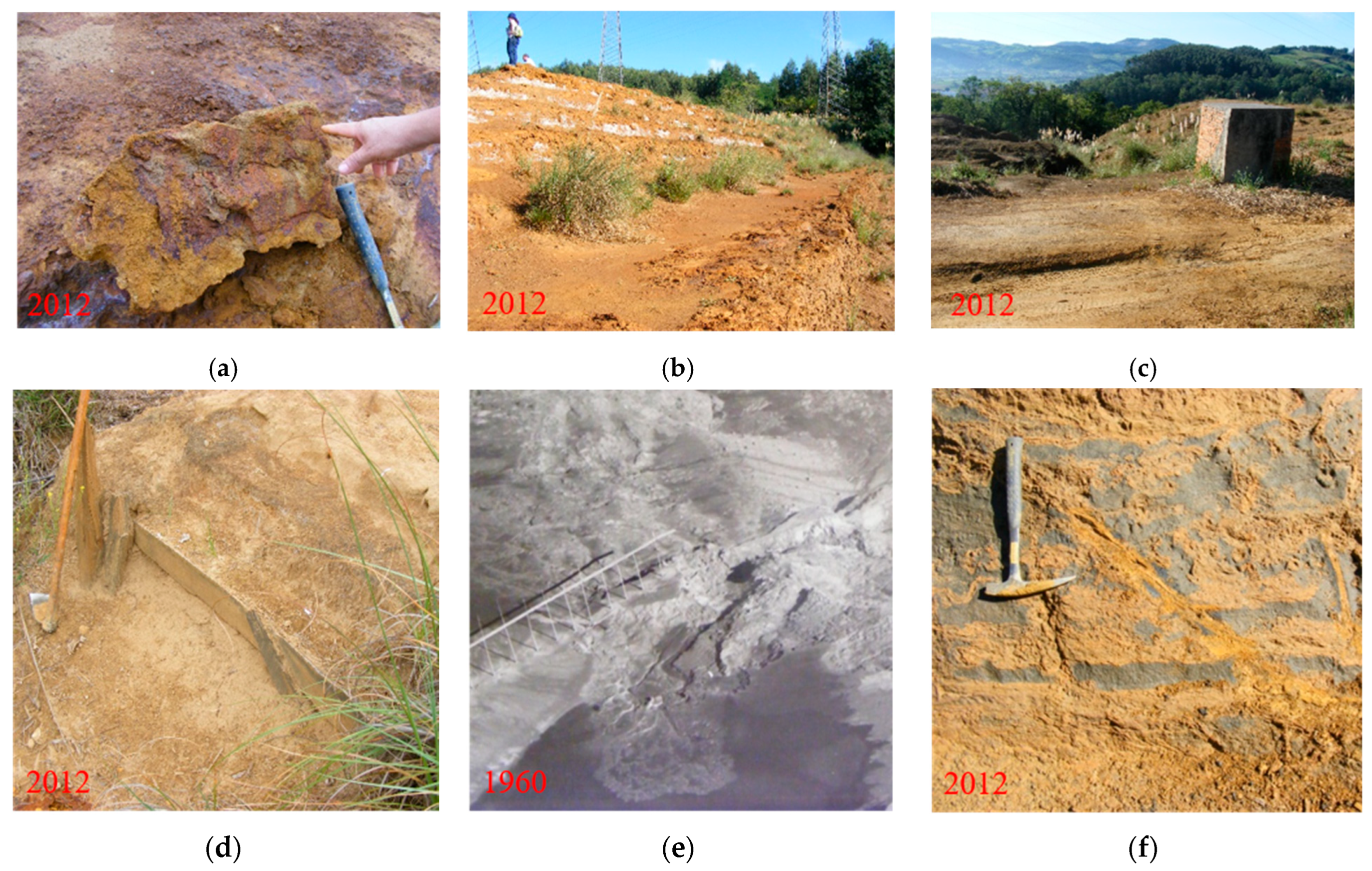
The TSF covered 9 hectares, with a dam length of 750 m and a storage capacity exceeding 1.25 Mm3. The main dam exhibited a plan layout with smooth transitions, whereas the lateral one did not follow gentle inclinations. The dam was built using wooden boards (Figure 3d). Each step measured 0.8 m in height, 2.4 m in width, and was inclined at 70° to the horizontal, with 4 m berms every 15 lifts, resulting in an average overall slope angle of 18° [16,17]. The initial wooden board remained embedded in the lower dam. After each step was completed, tailings were left to dry for 15 days to gain strength through drainage and atmospheric drying before the next discharge. At the time of construction, hydrometeorological factors such as rainfall infiltration and surface runoff were not considered in the design or operation of the tailings facility (no additional water catchment system was designed to collect and remove rainwater from the TSF). Due to weathering and mineralogical characteristics of the tailings, a ferruginous crust developed (Figure 3a), increasing the shear strength of the steps and influencing the overall slope stability.

2.3. The Drainage System

The drainage system of the La Luciana TSF consisted of gravity-flow pipes that conveyed water from the base of the collection sumps to the exterior of the dam. In this case, reinforced concrete pipes were installed beneath the dam body (Figure 2a,d). Compared with the other four TSFs in the region, the La Luciana facility experienced greater operational problems due to deficiencies in its original design [16].
The main shortcomings included the following: (i) concentration of the drainage system exclusively at the base of the dike (Figure 2e); (ii) partial siting of the deposit over a poorly consolidated old waste dump; (iii) alteration of the outer dike configuration during lateral expansion; and (iv) accelerated raising rates of the dam. To mitigate these issues, supplementary drainage was later implemented through wells placed at the reservoir’s toe and other critical zones. These wells were connected to horizontal drains (French drains) to facilitate discharge. In addition, piezometers were installed as a control measure, which was a standard practice for TSFs constructed during that period. No piezometers or any other method for monitoring the piezometric level were installed at the site at that time. This was primarily due to the absence of regulations mandating their installation.

2.4. The Decant System

The decant system at La Luciana comprised vertical collection sumps (Figure 3c) positioned within the reservoir to collect supernatant water. Each tower was fitted with gates or windows at multiple elevations to capture the clearest water, which was progressively sealed as the tailings level increased. The number of towers was determined by the surface area of the TSF and the hydrological characteristics of the site. Operational experience in the Cantabrian mining region suggested a guideline of one tower (or chimney) per hectare of TSF, assuming a maximum rainfall of 83 L/m2 over 24 h.
The decant system served three primary functions: (i) to separate water from the deposited tailings; (ii) to recover and convey clarified water either for reuse in mineral processing or, if necessary, for discharge after treatment; and (iii) to regulate the free water level within the reservoir, thereby ensuring dam stability and preventing infiltration or excessive hydraulic pressure on the dike.

2.5. The Geological Background

The main TSF was founded on an old waste rock dump and overlies marlstones, limestones, and dolomites. The permanent groundwater table was located beneath the lower waste dump, approximately coinciding with the water level of the Besaya River, situated 500 m east of the TSF. In the sector where the flowslide occurred, geological conditions were more complex due to the presence of two types of anthropogenic deposits derived from historical mining activities, underlain by the same lithologies as the main deposit (marlstones, limestones, and dolomites).

2.6. Hypothesis of the Cause of the Flow Failure of the La Luciana TSF

The initial analysis carried out by AZSA in October 1960, preserved in its historical archives, proposed two hypotheses for the TSF failure: (i) failure triggered by an earthquake, and (ii) overtopping of the lagoon. Both hypotheses were subsequently dismissed, as no seismic events or unusual rainfall capable of inducing geotechnical instability were recorded.
A third hypothesis was later advanced by [16], attributing the failure to defective foundation conditions beneath the lateral expansion constructed over an old waste dump (Figure 2e), in combination with deficiencies in the drainage system. Subsequently, ref. [17] proposed a fourth hypothesis, identifying static liquefaction of the tailings as the most plausible mechanism. This sudden failure was associated with the high degree of saturation of the tailings. Supporting studies concluded that, at the time of failure, conditions for static liquefaction were satisfied: saturated materials prone to contractive behaviour and elevated pore pressures. This interpretation is further supported by pre-failure photographs showing seepage through the downstream slope and a large pond adjacent to the dike (Figure 2b,c), together with the presence of sand dikes (Figure 3f) in unaffected tailings, documented more than 50 years later.

3. Materials and Methods

3.1. Geotechnical Characterization of Tailings

The geotechnical material characterization of the materials was based on both data obtained from investigations conducted by our research group and pre-existing geotechnical records, which are systematically evaluated throughout the article.
The initial in situ assessment was performed several months following the incident. However, the resulting data were neither subjected to analytical interpretation nor formally disseminated at that time.
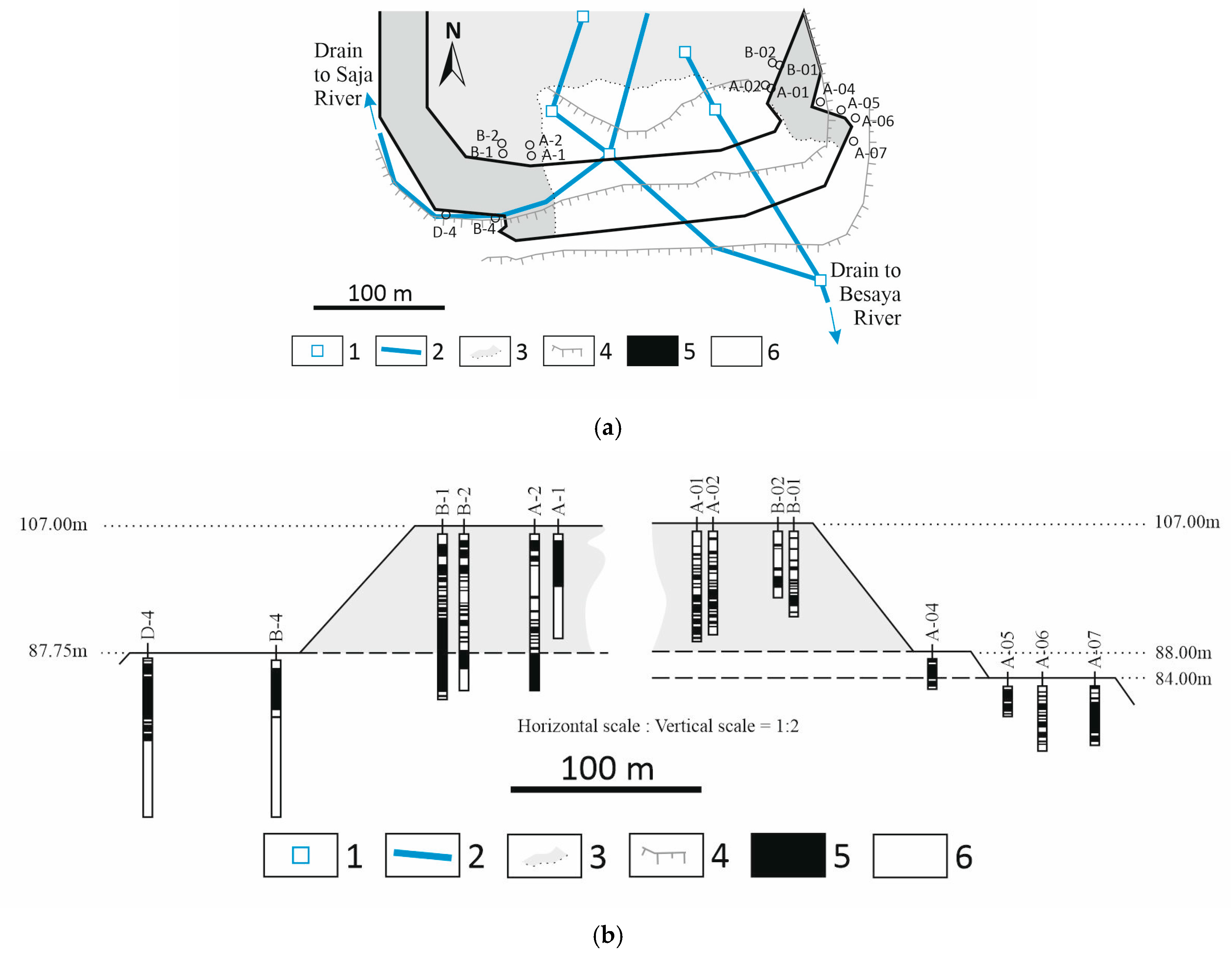
Among the technical documents reviewed were the results of 14 static cone penetration tests (CPTs) performed by the mining company (AZSA) that owned the TSF, between November 1960 and March 1961. These tests, conducted in the vicinity of the failure zone using a Gouda-type mechanical penetrometer [17], yielded, at that time, inconclusive results regarding the failure’s causes.
In order to supplement the available information, the Centro Nacional Instituto Geologico y Minero de España (CN IGME) carried out profiling, sampling, and in situ and laboratory testing in 2011. These studies classified the tailings based on physical, geotechnical, and hydraulic properties derived from laboratory testing, all performed in accordance with ASTM standards. The different types of testing are described in the following sections.

3.2. Measurement of Internal Friction Angle and Cohesion

The internal friction angle (φ) of the tailings was determined following the procedures of Standard Test Method for Direct Shear Test of Soils Under Consolidated Drained Conditions [19]. Undisturbed and remoulded samples were prepared at their natural moisture contents and compacted into shear boxes with dimensions of 60 × 60 mm. Each specimen was subjected to normal stresses of 50, 100, 200, and 400 kPa.
The specimens were first consolidated under the applied normal stress until a negligible volumetric change was observed. Subsequently, a horizontal displacement was imposed at a constant strain rate of 0.5 mm/min to ensure drained conditions. During shearing, both shear force and vertical displacement were recorded continuously until the specimen reached either a peak shear stress or a displacement equal to 15% of the specimen length.

3.3. Hydraulic Characterization of Tailings

The saturated hydraulic conductivity (ks) of the La Luciana tailings was determined in accordance with the most recent ASTM standards for soil and tailings testing. Laboratory tests were conducted on representative samples collected from different depositional zones, including the dike, discharge area, transition layers, and decant pond. Testing followed the procedures outlined in [20], which specifies methods for measuring saturated hydraulic conductivity of soils using flexible wall permeameters under controlled conditions. The adoption of standardized ASTM procedures ensures that the measured parameters are directly comparable with values reported in contemporary geotechnical practice, thereby providing a reliable basis for numerical modelling and stability assessment.

4. Results

This section presents both the historical background information compiled from previous reports [16,17,21,22,23], interpretation of a previous CPT with new methods and the original results obtained in this study, including new field, laboratory, and numerical analyses.

4.1. Geotechnical Characterization of Tailings

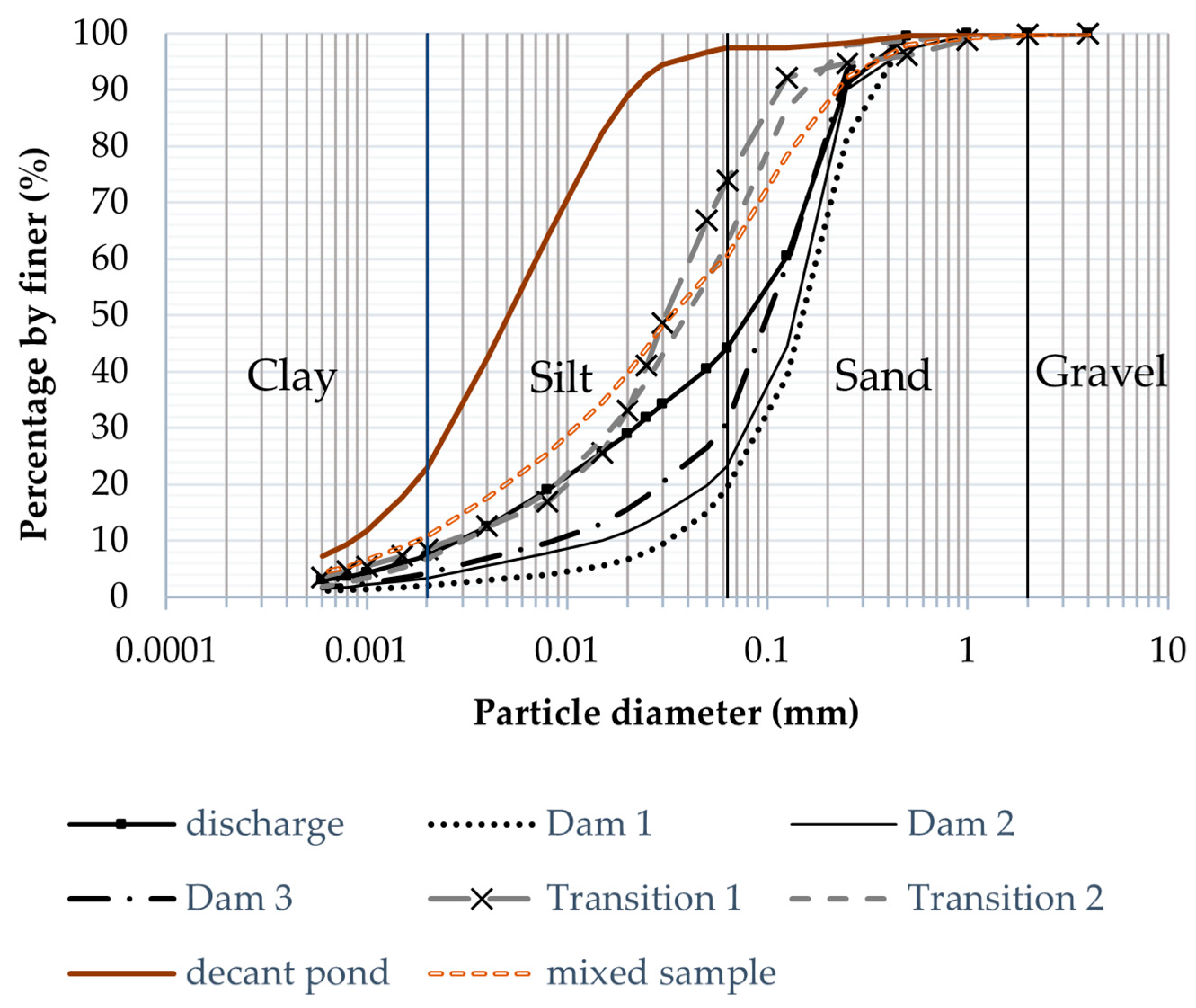
Figure 4 shows the particle size distribution (PSD) curves for samples collected from different areas of the TSF: dike, discharge, transition zone, and decant pond. The mixed sample represents a combination of 30 individual field samples. The overall tailings were classified as sandy silt, with fines (particles with a diameter of d < 63 μm) ranging between 17% and 97%. The sand dikes contained 17%–20% fines, whereas the decant pond material contained 97% fines. Particle density (Gs) ranged from 2.86 to 2.89 g/cm3. The tailings were generally non-plastic (NP), except for one decant pond sample, which exhibited plasticity with a liquid limit (wL) of 23.2%, a plastic limit (wP) of 18.5%, and a plasticity index (Ip) of 4.7.
Table 1 presents the main parameters derived from the PSD curves. According to the Unified Soil Classification System (USCS), the tailings were classified as well graded (Cu > 4 and 1 < Cc < 3), except for two samples (dike 3 and the mixed sample). Moisture content varied considerably across samples, ranging from 4.44% in the dike to 32.3% in the decant pond. Table 2 lists the values of internal friction angle (φ) and cohesion (c) for the La Luciana TSF reported in various studies.
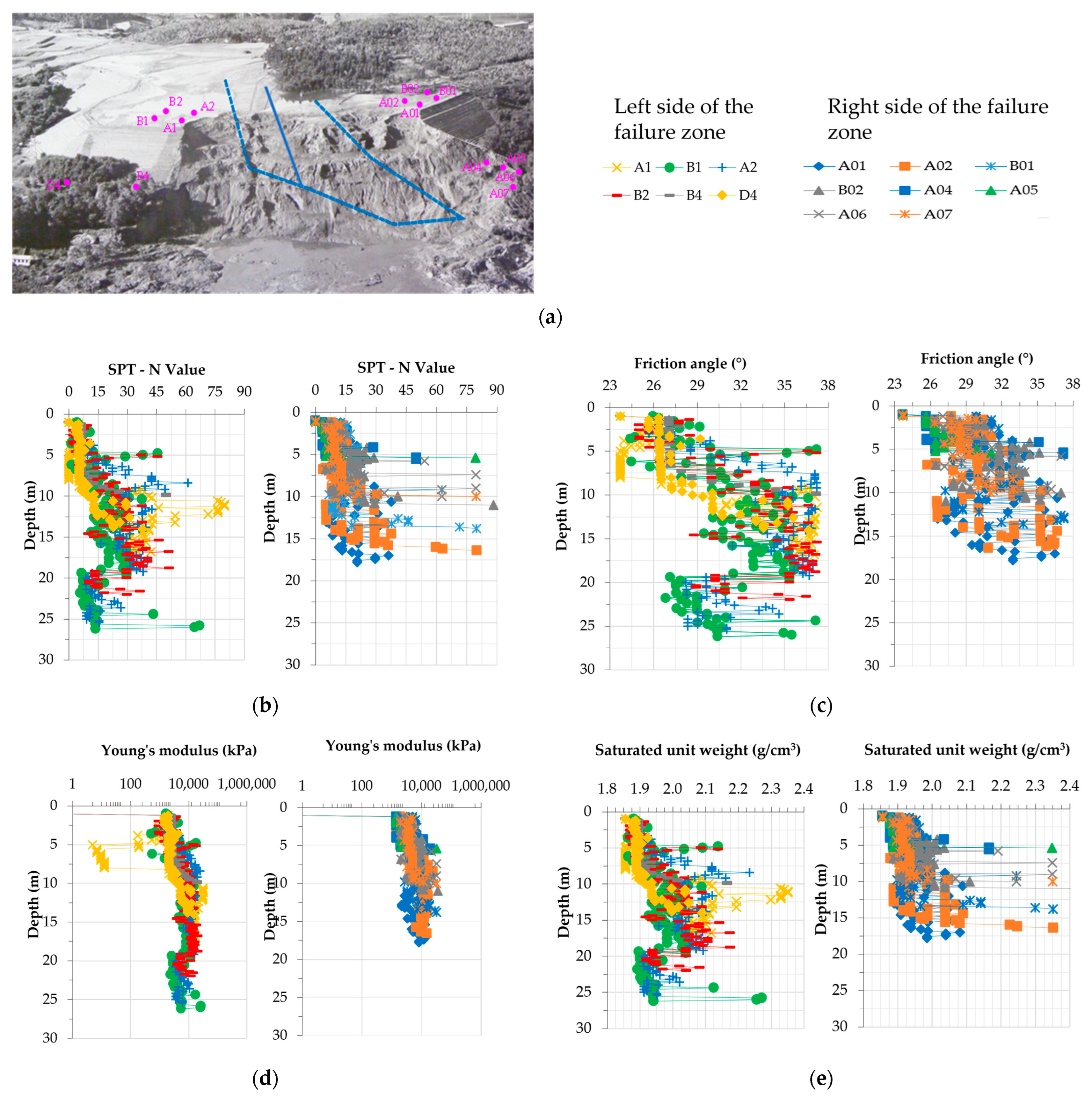
The authors found no comprehensive analysis of the CPTs performed immediately after the 1960 flowslide. Therefore, we reinterpreted the original mechanical CPT data by converting them to equivalent electrical values using correlations between SPT blow counts and cone resistance, as proposed by several authors [24,25,26,27,28,29,30]. These correlations are summarized in Table 3. The resulting parameters—friction angle, Young’s modulus, saturated density, and shear wave velocity—are illustrated in Figure 5.
The results in Figure 5c indicate that the internal friction angle ranges between 23° and 37°, with significant variability both vertically and laterally across the TSF. These values are consistent with [16,21], who reported φ = 36° for the dam and φ = 21° for remoulded tailings (Table 2). In contrast, ref. [22] estimated higher values using the expression proposed by [31], obtaining φ between 37° and 40° for tailings. Laboratory direct shear tests from this study confirmed similarly high values, which may be partly attributed to the preparation of remoulded samples, known to influence shear strength measurements.
Importantly, all estimated friction angles (Figure 5c) exceed the average slope angle of the dam (18°), which by itself should not compromise stability. The observed heterogeneity—differences of up to 10°—can be explained by (a) stratification of tailings with variable thicknesses (Section 4.3), (b) differential consolidation induced by alternating wetting and drying cycles, and (c) self-weight consolidation due to progressive deposition.
Regarding stiffness, Young’s modulus values in the upper 4 m of all boreholes were notably low, not exceeding 8 MPa (Figure 5d). Borehole A1 recorded the lowest stiffness, with values approaching 0 kPa between 4 and 8 m depth. Conversely, the highest stiffness values—exceeding 30 MPa—were measured between 5 and 13 m in several boreholes. The spatial variability of Young’s modulus reached over 20 MPa across boreholes. Saturated density ranged from 1.85 g/cm3 to 2.35 g/cm3, with the lowest value also observed in borehole A1. Within a single borehole, density varied by up to 1.5 g/cm3—for example, in A1 it increased from 1.85 g/cm3 at 5–7 m depth to 2.35 g/cm3 at 10–12 m.
These marked variations in friction angle, stiffness, and density highlight the heterogeneity and anisotropy of the tailings. The combined geotechnical and hydraulic characterization, based on both in situ and laboratory testing, identified three distinct types of tailings implicated in the failure. These materials exhibited spatially variable strength, stiffness, and hydromechanical behaviour.

4.2. Hydraulic Characterization of Tailings

Laboratory tests performed according to ASTM D5084-21 [20] (flexible wall permeameter) provided estimates of saturated hydraulic conductivity (ks) for different depositional zones of the La Luciana TSF. The results (Table 4) show a wide variability in ks values across the impoundment, reflecting the heterogeneous grain size distribution and depositional processes.
The highest hydraulic conductivities were measured in coarse-grained sand dams, with ks values on the order of 10−5 to 10−6 m/s. These values are typical of permeable sandy tailings, where drainage pathways can develop, promoting preferential seepage. The dam samples also showed moderately high conductivity (10−6 m/s), consistent with their lower fines content (≈20%). In contrast, fine-grained tailings from the decant pond exhibited extremely low ksat value (≈10−9 m/s), typical of nearly impermeable silty–clayey deposits with fines content exceeding 95%. Transition zones and discharge areas presented intermediate conductivity (10−7–10−8 m/s), reflecting mixed textures with higher fines percentages (40%–60%).
These results highlight a strongly stratified hydraulic behaviour. Coarse sand dams and dam sectors could act as preferential seepage conduits, while fine-grained tailings in the pond behave as aquitard layers, retaining pore water and favouring elevated pore pressure development. This stratification is consistent with the observed contractive–dilative alternation identified in the CPT profiles (Section 4.1).
From a geotechnical perspective, the presence of very low-permeability horizons interbedded with permeable layers suggests conditions favourable to undrained loading and excess pore pressure generation during rising stages of the TSF. These conditions are known precursors to static liquefaction. Thus, the hydraulic characterization not only explains the heterogeneous pore pressure regime inferred from field evidence but also corroborates the forensic hypothesis that inadequate drainage and high saturation contributed significantly to the 1960 failure.

4.3. Evaluation of CPT-Based Soil Classification Methods

4.3.1. Soil Type Classification

It should be noted that the data and materials used correspond to the tailings that were not affected by the flowslide of the tailings dam. In the analysis, the data are separated into the left and right sides of the failure zone to facilitate understanding.
In this study, the methods proposed by [32,33,34] were applied to analyze CPTs performed in tailings. Detailed explanations of each method are available in the original publications. It is important to note that the classification system, which relies solely on two measurements—cone resistance (qc) and sleeve friction (fs)—is generally considered less reliable. This method is best suited for predominantly silica-based, young, uncemented soils (i.e., ideal soils). Nevertheless, an attempt has been made to apply it to tailings in this study. By using cone penetration test (CPT) data—specifically cone resistance (qc) and sleeve friction (fs)—it is possible to estimate soil type. The Soil Behaviour Type (SBT) chart developed by [32] and later updated in [34] is the most widely used tool for this purpose. This chart utilizes the corrected cone resistance, qt (where qt = qc if pore pressure u = 0), and the friction ratio, Rf, defined as follows:
R f = f s q c × 100 % ,
The chart classifies soils into 12 distinct types based on the relationship between cone resistance, sleeve friction, and in situ stress conditions. This preliminary classification provides valuable insight into subsurface conditions using CPT data. Ref. [35] provides an update in terms of dimensionless cone resistance qc/pa and Rf on log scales. It also reduces the number of soil behaviour types to 9, matching the [33] chart. The refined version of the original profiling chart by [33], plotting normalized for the in situ vertical stress with the stress exponent cone resistance (Qtn) against the normalized friction ratio (Fr) in a cone resistance chart as follows:
Q t n = q t σ v p a × p a σ v n
F r = f s q t σ v × 100 %
n = 0.381 × I c + 0.05 × σ v p a 0.15
I c = 3.47 log Q t 2 + log F R + 1.22 2 0.5
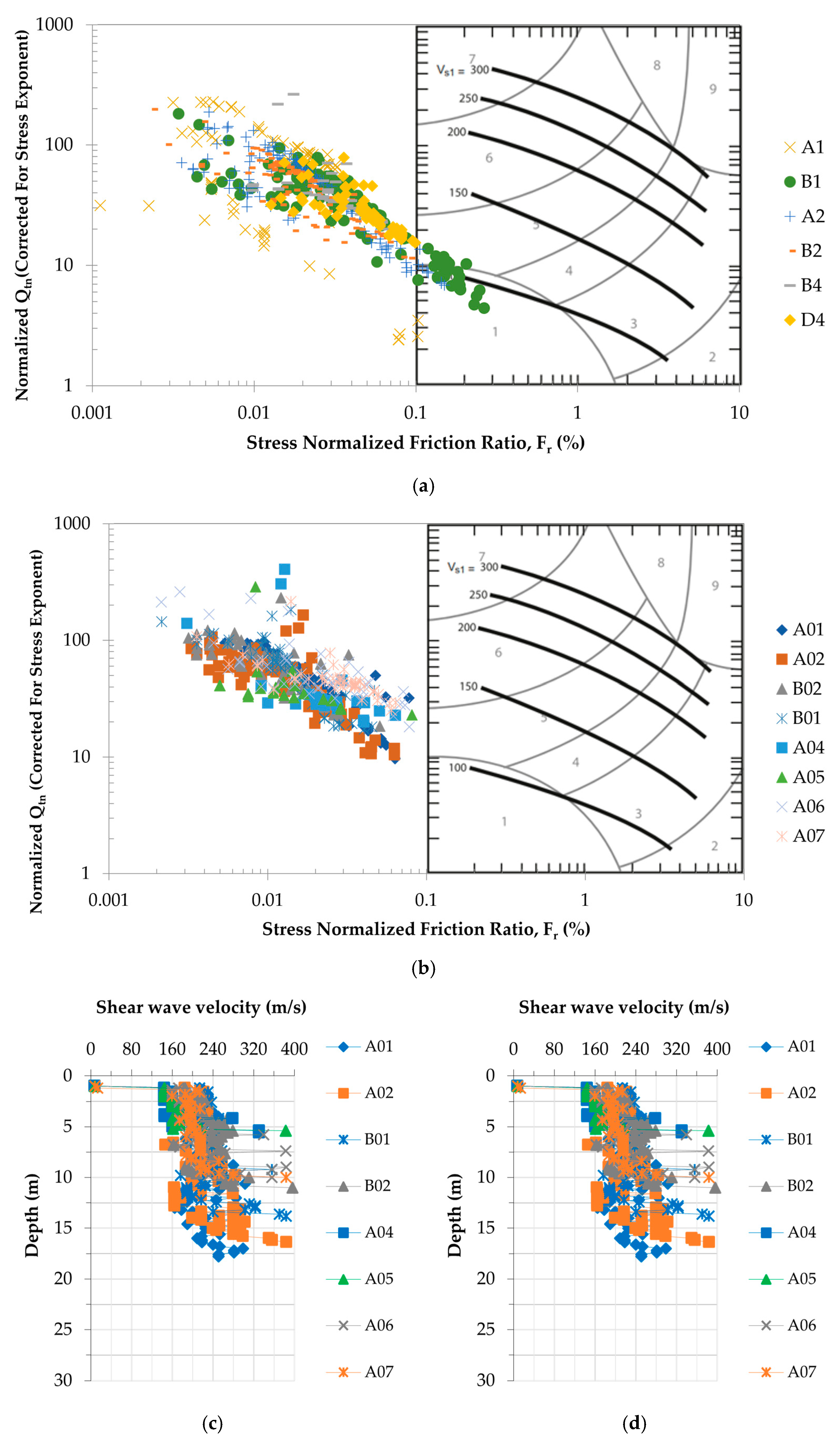
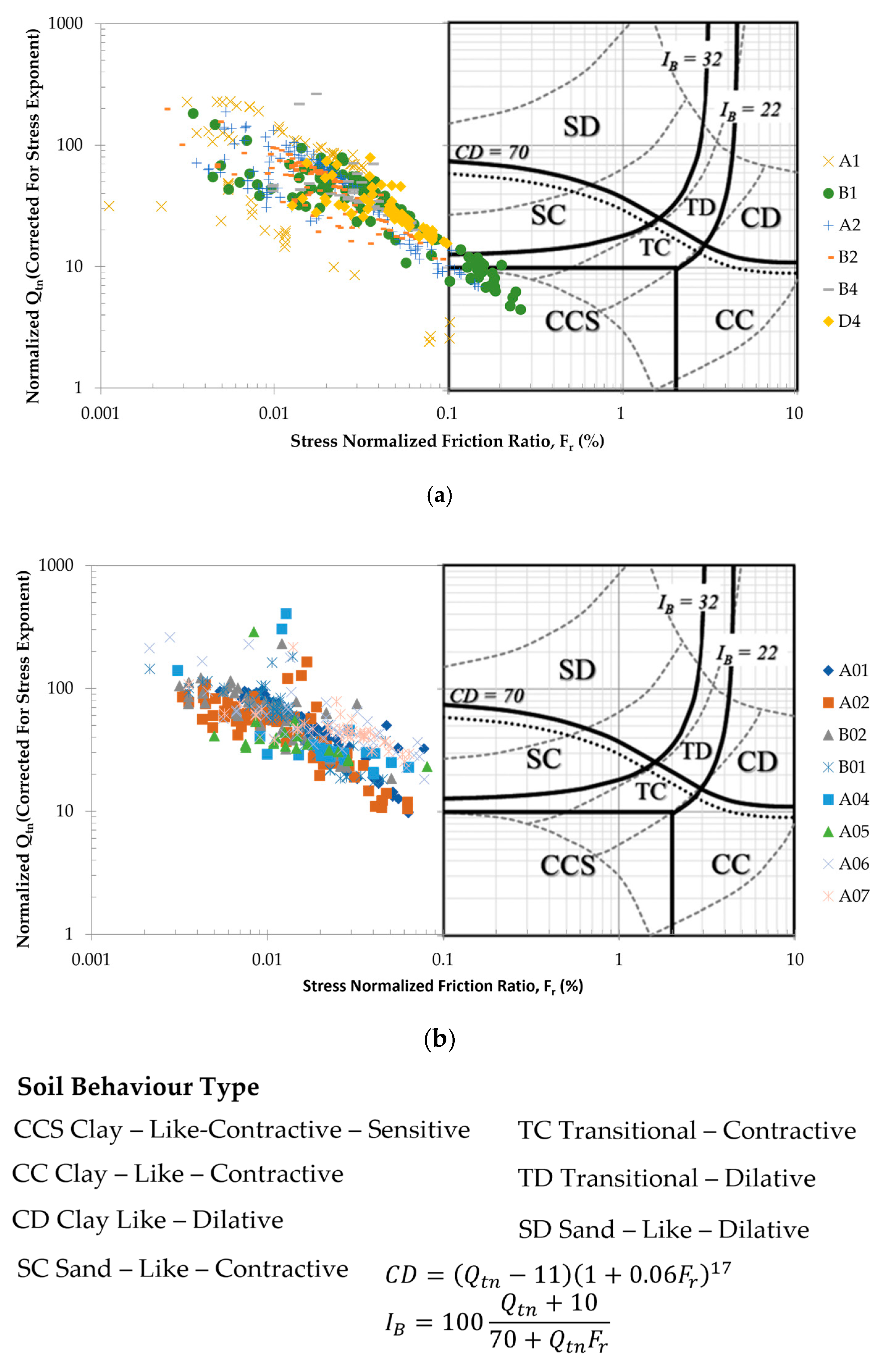
where pa = 101.325 kPa is an atmospheric pressure and Ic is the soil behaviour type index defined by [36], qt = qc and σ’v = σv (u = 0). This updated classification keeps the number of soil behaviour types at nine, enhancing interpretability while maintaining consistency with earlier frameworks. The CPT data plotted on the normalized soil behaviour type chart (Figure 6) shows that most points fall outside the standard classification zones, primarily toward very low stress-normalized friction ratios (Fr < 0.1%) and high normalized cone resistance (Qtn > 10). This pattern reflects the atypical nature of tailings compared to natural soils. Only a small subset of data overlaps with zones corresponding to sensitive fine-grained soils and sand–silt mixtures, indicating localized similarities. In contrast, data from the right side of the breach remain largely undefined within the chart. Although extending the zone boundaries beyond the original chart shows that most data points would fall within zones 1, 5, and 6 (sensitive fines, sand mixtures, and sands), these values remain outside the range proposed by the author and therefore cannot be reliably interpreted. Consequently, constructing a soil profile from borehole logs using colour-coded classification would inevitably introduce discontinuities, reducing the accuracy and consistency of the interpretation.

4.3.2. Contractive-Dilative Tailings Behaviour

The contractive-dilative tailings behaviour was analyzed with two methods: (a) an updated normalization procedure for cone resistance and the associated Soil Behaviour Type normalized (SBTn) [35] and (b) the criterion of [37] based on effective vertical stress (σ′v0) and normalized tip resistance (qt).
Ref. [35] updated the normalization procedure for cone resistance and the associated Soil Behaviour Type normalized (SBTn) chart by introducing a variable stress exponent, n (Equation (4)), in the normalization process. This approach accounts for the influence of overburden stress more accurately. Their refinement improves the reliability of soil classification, especially in layered or overconsolidated profiles. The CPT results were included in the figures proposed by [36] and are presented in Figure 7.
Although some values fall within the chart, specifically in the contractive sand (CS) and clay-like contractive sensitive (CCS) zones, the majority lie outside the range proposed by the original author. Therefore, the correlation suggested by [37] was adopted for further analysis. This correlation also allows the direct determination of the contractive or dilating nature of the material without the need for analysis of additional parameters, such as the sensitivity of the material. In this way, it has been possible to establish the contractive-dilatant nature of the mining waste and the spatial distribution in depth of the levels most susceptible to liquefaction in each of the boreholes where CPTs were carried out, taking this factor into account. This analysis was similar to that performed by [17]. The boundary relation between contractive and dilative is approximately to
σ v 0 b o u n d a r y = 1.1 × 10 2 × q c 4.79
where σ v 0 and q c have a unit of kPa and MPa, respectively. Records of cone resistance versus vertical effective stress are plotted alongside the liquefaction susceptibility relationship (Equation (6)). Data points located to the right of the boundary line indicate dilative behaviour, while those on the left suggest contractive behaviour. Figure 8 presents a comparison between the two vertical profiles located on the left-hand and right-hand sides of the fault zone.
These results agree with laboratory evidence and field observations, which confirm that the left-hand sector of the impoundment contained finer, more saturated materials prone to undrained loading conditions and static liquefaction. The right-hand side, with alternating dilative horizons, may have partially resisted failure propagation. This contrast explains the retrogressive pattern of the 1960 flowslide, as the initial failure likely originated in contractive layers on the left-hand side and then propagated across the impoundment.
Two complementary CPT-based approaches were used to evaluate the contractive or dilative tendency of the tailings. Figure 7 represents the soil behaviour type (SBT) classification according to [35], whereas Figure 8 shows the variation in the behaviour index (Ic). The latter provides a more continuous and sensitive indicator of contractive behaviour, identifying fine, saturated materials (Ic > 2.6) consistent with the overall depositional environment. Therefore, the results are not contradictory but complementary: the SBT chart identifies discrete contractive layers, while the Ic index confirms a general contractive tendency of the tailings under undrained loading.

4.4. Shear Wave Velocity (Vs)

It should be noted that no direct measurements of shear wave velocity (Vs) were obtained in this study; all Vs values discussed herein were inferred from empirical correlations based on CPT data and laboratory-derived stiffness parameters. Analysis reveals that the tailings exhibit very low and highly variable shear wave velocities, indicative of unconsolidated materials. According to the Spanish Seismic Design Code [38] (Table 5), the tailings from all boreholes (Table 3) are classified as Soil Type III: medium-dense granular soils or cohesive soils of firm to very firm consistency, with shear wave velocities (Vs) ranging between 200 m/s and 400 m/s. A notable exception is borehole A1, where a significant portion of the tailings is classified as Soil Type IV: loose granular soils or soft cohesive soils, with shear wave velocities of Vs ≤ 200 m/s. This borehole is situated closest to the failure zone and the slope surface and exhibits the greatest variability in geotechnical properties. Specifically, A1 shows the lowest values for SPT blow count, friction angle, Young’s modulus, and density (Figure 5).
The CPT data plotted against the chart with Vs1 contours (Figure 9a,b) indicates that most points fall outside the standard soil behaviour zones, clustering at very low stress-normalized friction ratios (Fr < 0.1%) and moderate to high normalized cone resistance (Qtn between 10 and 300). The Vs1 contours (extent beyond the chart) suggest shear wave velocities predominantly below 150–200 m/s, characteristic of very loose, contractive materials with low stiffness. Only a few points approach the 200–250 m/s range, indicating localized denser zones. These results confirm that the tailings exhibit highly contractive behaviour and low strength.
If we compare the shear wave velocity obtained using Robertson’s method [33] with that estimated by [30], we can see that the results are similar (except for the extreme values) (Figure 9).
The shear wave velocity (Vs) profiles derived from correlations (Table 3) are presented in Figure 9c,d. The estimated Vs values range between 120 and 260 m/s, consistent with silty and sandy tailings of low to medium stiffness. The upper 4 m of both profiles exhibit the lowest Vs values (<150 m/s), reflecting loose tailings with high void ratios and limited cementation. At greater depths, Vs progressively increases, exceeding 200 m/s in several intervals, particularly in coarser sand-rich horizons.
Figure 9. Contours of normalized shear wave velocity, Vs1, on normalized Qtn–Fr chart for uncemented Holocene- and Pleistocene-age soils after [33]: (a) Left side of the breach; (b) Right side of the breach; and shear wave velocity calculated after [30]: (c) Left side of the breach; (d) Right side of the breach.
Minerals 15 01131 g009
The left-hand profile shows a relatively uniform increase in vs. with depth, although values remain below 200 m/s across most of the stratigraphy, confirming the predominance of contractive fine tailings. In contrast, the right-hand profile displays stronger vertical variability, with alternating low- and high-Vs layers. These intervals coincide with the alternation of contractive and dilative strata identified from the Ic index, suggesting a strong link between soil behaviour type and stiffness.
The Vs values obtained are consistent with the low Young’s modulus values estimated in Section 4.1, especially in the upper layers where stiffness is minimal. These findings highlight the heterogeneity of mechanical behaviour across the impoundment, reinforcing the interpretation that stratification and differential stiffness contributed to the retrogressive failure mechanism of the La Luciana TSF.

4.5. Mineralogical Composition of Tailings

The mineralogical composition of the tailings was determined by X-ray diffraction (XRD) and confirmed by scanning electron microscopy coupled with energy dispersive spectroscopy (SEM–EDS) on representative samples collected from the decant, transition, and discharge zones.
The dominant phases are siderite (FeCO3, 30%), phyllosilicates (27%), and quartz (21%), with subordinate amounts of dolomite (6%), plagioclase (6%), calcite (3%), and K-feldspar (3%), as well as trace gypsum (<1%). The presence of siderite reflects the geochemical conditions of the ore-processing residues derived from carbonate-hosted Zn–Pb mineralization. Its partial oxidation under atmospheric exposure likely contributed to the formation of secondary Fe oxyhydroxides along microfractures and pore surfaces, locally reducing permeability.
The relatively high content of phyllosilicates (mainly illite and chlorite) contributes to the low hydraulic conductivity (≈10−9 m/s) and the plastic, contractive behaviour observed in the fine-grained pond deposits. These minerals favour water retention and capillary rise, consistent with the evidence of saturation exceeding 20 m below the surface.
Quartz and feldspars, which dominate the sandier fractions, are mechanically stable but display low surface reactivity, playing a minor role in the hydrogeochemical evolution of the tailings. However, the contrast between these coarse, dilative layers and the fine, contractive horizons rich in phyllosilicates and siderite explains the stratigraphic heterogeneity that controlled the differential response of the deposit during loading and failure.
Overall, the mineralogical composition supports the interpretation that mineralogical and textural variability strongly influenced the hydro-mechanical behaviour of the tailings, promoting pore-pressure accumulation and static liquefaction under progressive saturation conditions.

4.6. Definition of Geometry and Materials Properties

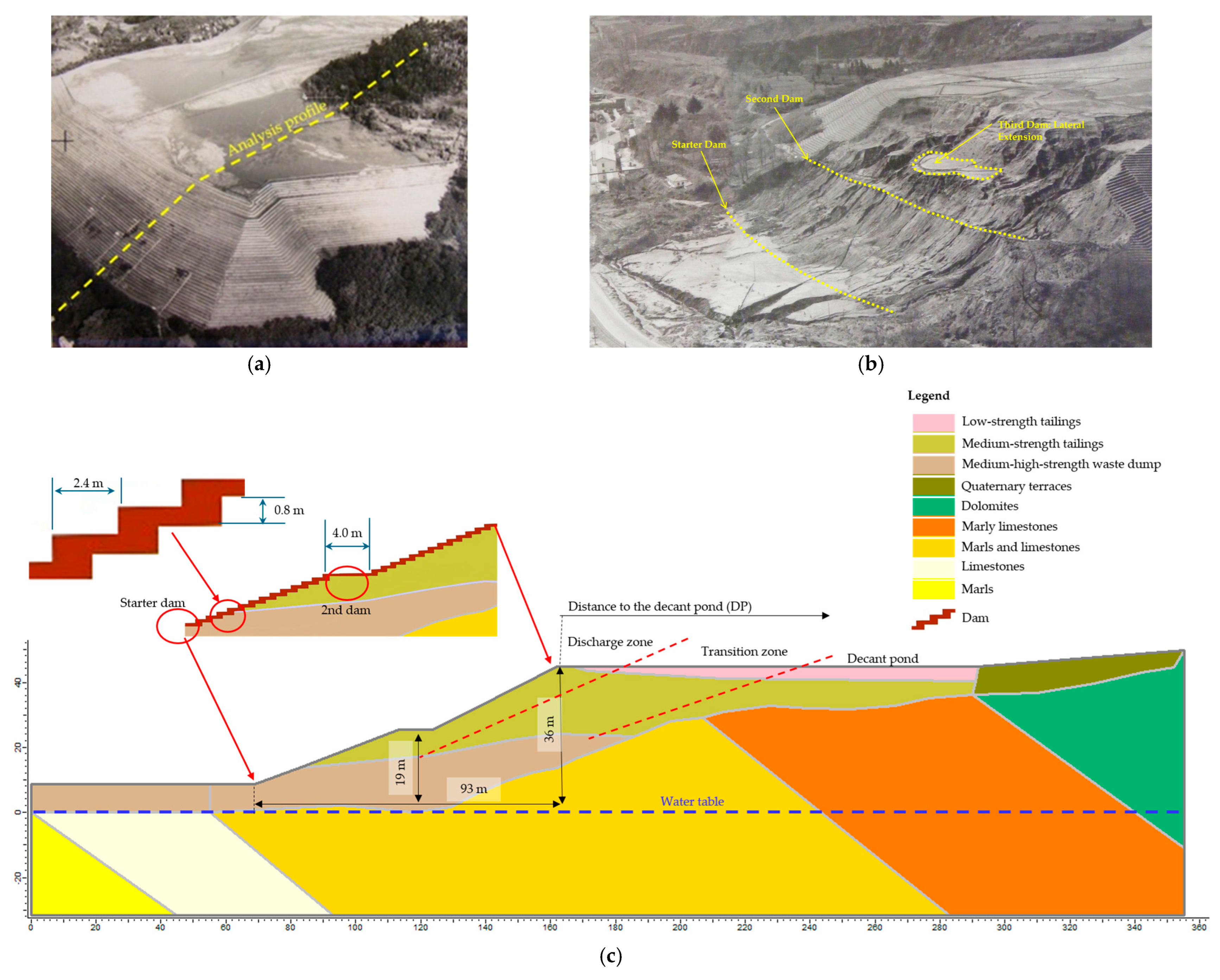
The digitization and georeferencing of sketches, topographic surveys, historical photographs, and in situ surveys and sampling provided essential information on the geometry of the TSF and the spatial distribution of materials before and after the breach (Figure 10a,b). These datasets were used to establish the boundary conditions of the conceptual hydro-mechanical model applied in the numerical simulations (Figure 10c). Material properties were derived primarily from CPT reinterpretation and complemented by laboratory testing results.
The material zonation adopted for the modelling integrates field, laboratory, and historical evidence into a simplified classification suitable for numerical analysis. The dike, discharge, transition, and decant pond zones described earlier were represented by three mechanical material classes (low-, medium-, and medium–high-strength) consistent with the observed variation in density, permeability, and shear strength. The boundaries were defined based on borehole logs, field photographs, and construction records, providing an approximate but realistic spatial interpretation according to the methodology developed by [39].
For modelling purposes, the TSF was divided into four main material groups: (i) dam constructed from tailings, (ii) deposited tailings within the impoundment, iii) waste dump and (iv) foundation units comprising quaternary terraces, dolomites, marly limestones, marls, and limestone–marl sequences. Each group of materials was further subdivided into low-, medium-, and medium–high-strength classes (Table 6). The classification was based mainly on variations in friction angle (φ′), stiffness (Young’s modulus), and unit weight (Figure 5b–d), and was supported by laboratory direct shear and oedometer testing.
Cartographic evidence from that period indicates that these dams reached thicknesses between 5 and 15 m in the lateral expansion area (Figure 10b).
The geotechnical and hydraulic parameters assigned to both the tailings and the foundation materials in the numerical model are summarized in Table 7. The anisotropy ratio of horizontal to vertical permeability (kh/kv) was set to 10, following published recommendations for stratified fine-grained materials [40]. Laboratory tests on remoulded tailings [20] indicated vertical permeabilities in the order of 10−8–10−9 m/s, consistent with fine silty tailings. Given the observed stratification, with sand lenses and ferruginous crusts acting as preferential flow paths and local barriers (Figure 3 and Figure 8), a kh/kv ratio of 10 was considered appropriate to represent horizontal drainage. This value is supported by the range of 5–20 reported in [40,41,42]. Case histories and numerical analyses [43,44] further confirm that ratios between 5 and 15 are typically adopted in seepage modelling of stratified tailings. Sensitivity analyses carried out in this study showed that varying the anisotropy ratio between 5 and 15 produced negligible changes in the phreatic surface and factors of safety. Therefore, the chosen value of 10 was regarded as both realistic and conservative for the La Luciana TSF. The digitization and georeferencing of sketches, topographic surveys, historical photographs, and in situ ground surveys and sampling provided critical information on the TSF geometry and the spatial distribution of materials before and after the breach (Figure 10a,b). Based on this dataset, the boundary conditions of the conceptual hydro-mechanical model for numerical simulations were defined (Figure 10c). Material properties were derived from CPT reinterpretation and complemented with laboratory results.
The Mohr–Coulomb parameters adopted for the limit equilibrium and numerical analyses correspond to undrained effective stress conditions and represent peak strengths. These values were derived from laboratory shear tests and CPT-based correlations consistent with the contractive, low-permeability nature of the tailings. Residual strengths were not considered, since the objective of the analysis was to reproduce the pre-failure stability conditions rather than the post-failure stage.
The three tailings materials (low-, medium-, and medium–high-strength) defined in Figure 10 represent a simplified mechanical zonation derived from the previously described lithological domains (dike, discharge, transition, and pond zones). This subdivision was developed to assign representative Mohr–Coulomb parameters consistent with laboratory, CPT, and field data. The boundaries were established using available documentation, borehole logs, and photographic evidence, and therefore should be interpreted as approximate rather than exact limits.

4.7. Numerical Simulations

This section integrates the results obtained from field investigations, laboratory testing, and numerical analyses to provide a unified forensic interpretation of the La Luciana TSF failure. The objective is to identify the sequence of processes that governed the initiation, propagation, and development of the cascading failure mechanism.
A steady-state groundwater seepage analysis was performed in combination with limit equilibrium and stress–strain methods. The main objective was to quantitatively assess the geotechnical stability of the TSF, considering the hydro-mechanical conditions prior to the breach. The methodology comprised three phases:
(i)
Seepage analysis: computation of steady-state solutions for different distances between the decant pond (distal zone) and the dam;
(ii)
Stability analysis: determination of safety factors and potential breach surfaces corresponding to the steady-state solutions;
(iii)
Stress–strain analysis: computation of displacements for the steady-state solutions.
Transient seepage analyses were not considered because there were no reports of heavy rainfall, increased tailings discharge volumes, or drainage system failures in the days preceding the collapse that would suggest a significant rise in water inflow to the impoundment. According to documents and witness testimonies, the decant pond was expanding at a normal and relatively slow rate. Therefore, the assumption of steady-state flow conditions was considered appropriate to simulate the hydraulic behaviour of the TSF.
A two-dimensional conceptual model was developed to simulate the hydro-mechanical behaviour of the TSF and to assess its geotechnical stability at the time of failure. The tailings and foundation were modelled as linear-elastic, perfectly plastic materials governed by the Mohr–Coulomb failure criterion. Limit equilibrium analyses (LEM) were carried out using Slide2 v.9.0 [45], whereas stress–strain analyses were performed with the finite element method (FEM) in RS2 v.8 software [46]. The model mesh consisted of 6-noded triangular elements, with a total of 6930 elements and 14,057 nodes. In the FEM simulations, horizontal boundaries were fixed along the x-axis, and vertical displacements were restrained at the model base. Hydraulic boundary conditions were imposed in terms of hydraulic head and pore pressure.
The choice of modelling software has inherent advantages and limitations. For the LEM analyses, Slide2 v.9.0 offers robust implementations of several limit equilibrium formulations (e.g., Spencer, Morgenstern–Price, GLE) and allows noncircular slip surfaces and complex pore pressure conditions to be incorporated. Its main advantage is the flexibility in handling stratigraphic heterogeneity and pore-pressure distributions; however, a limitation is that LEM assumes rigid-body motion along predefined slip surfaces and does not capture progressive failure. For the FEM analyses, RS2 v.8.0 enables coupled stress–strain and seepage analysis under the Mohr–Coulomb criterion. FEM provides insight into deformation patterns, strain localization, and pore-pressure distributions, complementing LEM by offering a more detailed picture of failure mechanisms. Its main limitations lie in the reliance on simplified constitutive models (linear-elastic, perfectly plastic in this study) and in mesh discretization effects. While results may vary slightly if other modelling platforms were used—due to different search algorithms or shear strength reduction implementations—the combined use of Slide2 and RS2 ensures robust, consistent, and widely accepted outcomes in geotechnical practice.
For the geotechnical and hydraulic properties of the materials, the values reported in Table 7 were adopted. Differences between tailings types were evident in the strength and stiffness parameters obtained from in situ tests performed a few days after the failure (Figure 5). Additionally, the hydraulic properties varied as a result of segregation effects and the macro- and micro-stratification caused by deposition, disposal, and consolidation processes.
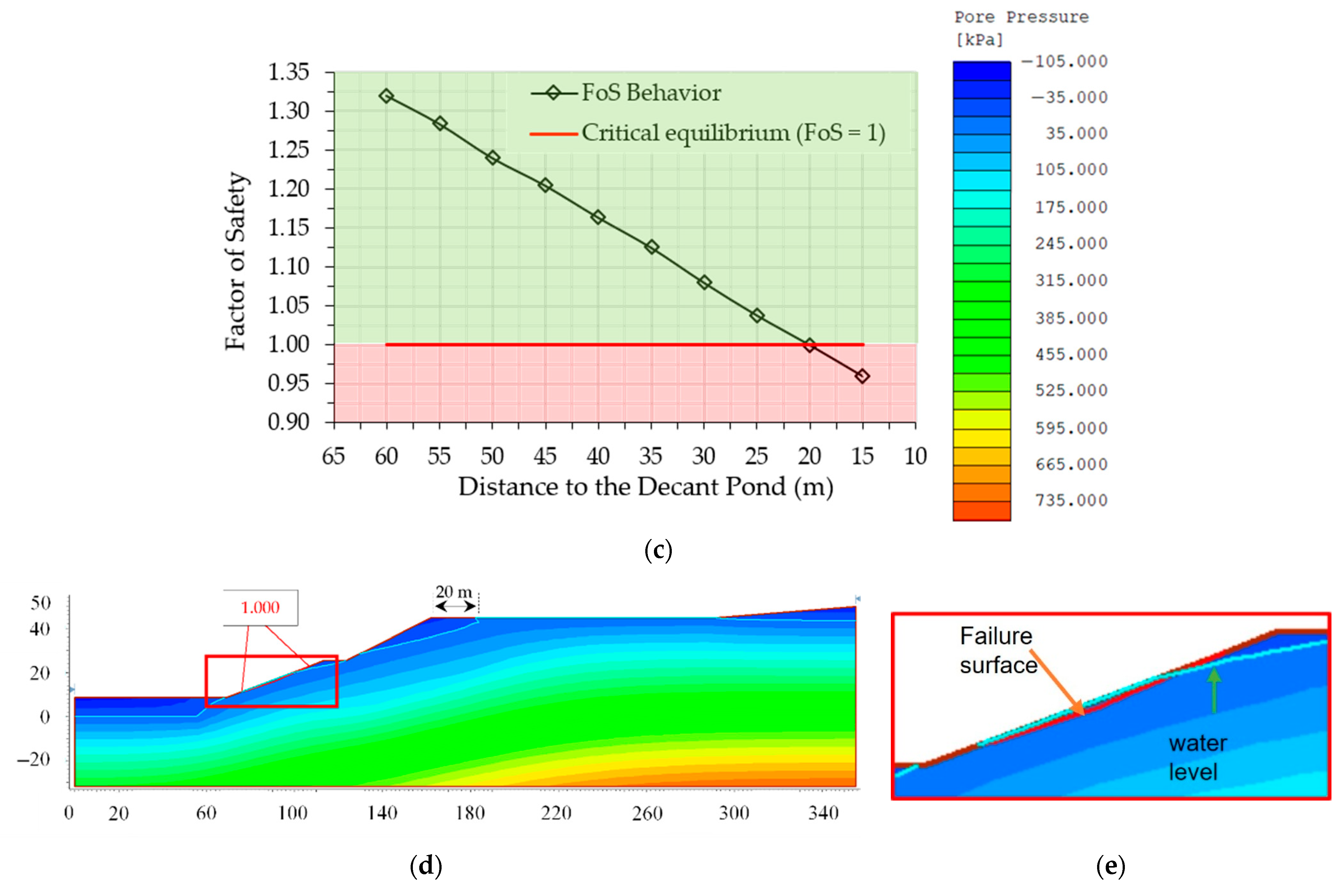
A finite element seepage analysis was conducted for several scenarios (10 cases), varying the distance between the decant pond and the dam from 15 to 60 m (Figure 11). Two representative cases, with decant pond positions at 60 m and 20 m from the dam, are presented in detail below. In each model, the phreatic surface, pore water pressures, and factors of safety (FoS) were determined. The FoS values were computed using limit equilibrium methods (GLE/Morgenstern–Price and Spencer) with non-circular slip surfaces [47,48,49] to evaluate stability. Finally, stress–strain analyses were performed to calculate displacements in the zones with the highest probability of failure.
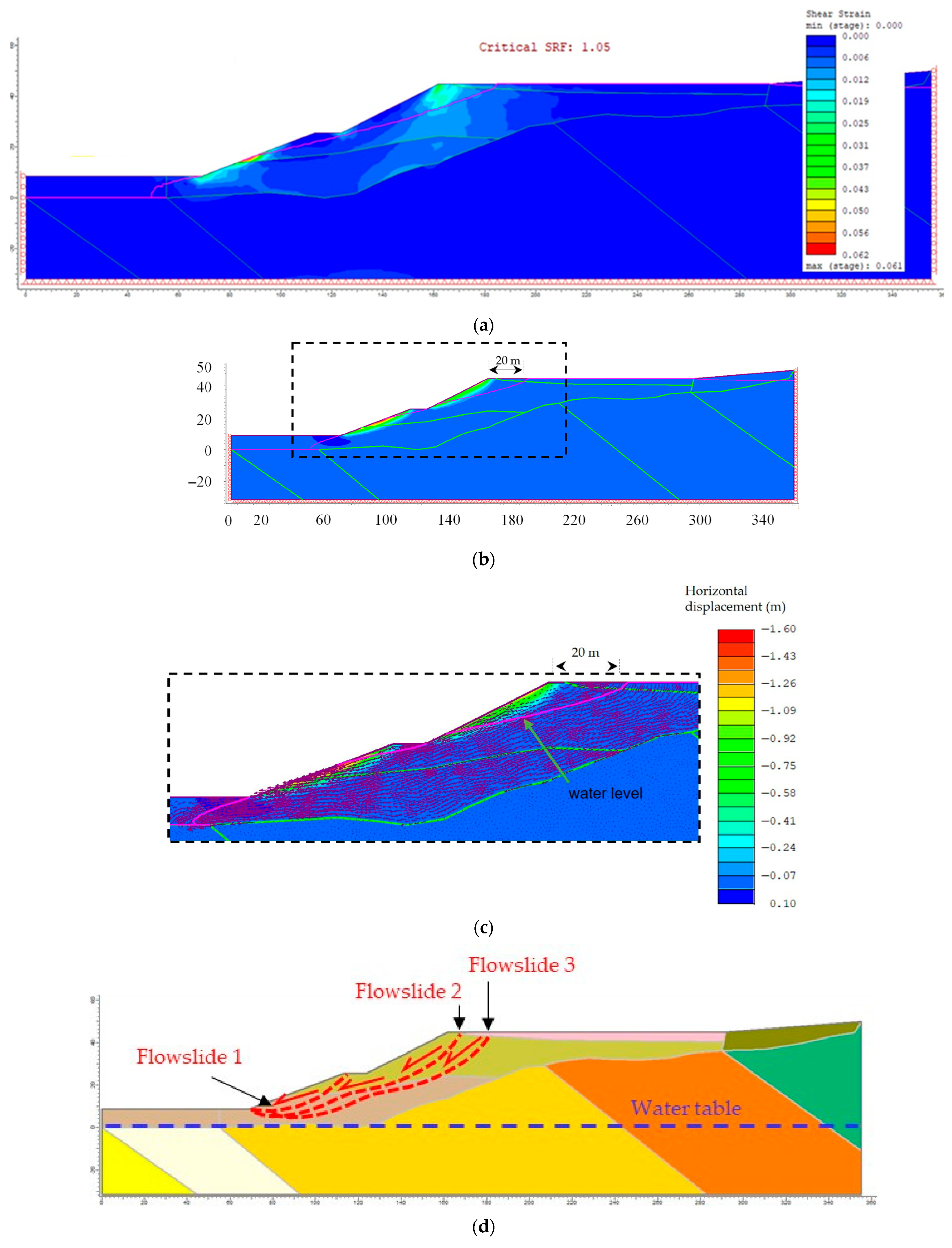
The results indicate a significant reduction in the factor of safety (FoS) as the decant pond approached the tailings dam, reaching critical equilibrium conditions (FoS = 1) at a distance of 20 m (Figure 11). This outcome is consistent with evidence that the decant pond was situated less than 20 m from the dam immediately prior to the onset of flow failure.
Figure 12 illustrates the shear strains, horizontal displacements, and seepage vectors associated with the critical equilibrium condition. The FEM stress–strain analysis showed that maximum shear strains and horizontal displacements, reaching ~1 m during the initial slip event (Figure 12b), were concentrated at the mid-slope, coinciding with historical seepage observations and eyewitness reports of sudden movement. The seepage vectors (Figure 12a) represent relative flow rates, with longer vectors indicating higher velocities and shorter vectors slower seepage. Notably, vectors plotted above the piezometric line (zero pressure) demonstrate that seepage persisted under negative pore pressures because the materials remained saturated by capillary action [44,45]. For the La Luciana TSF, the estimated capillary rise, based on grain size and density values, exceeds 20 m [50,51] and Table 1. The overlap of high shear strain zones with contractive layers identified in CPT profiles suggests that stratigraphic heterogeneity may have conditioned the initiation of failure, rather than conclusively demonstrating it. This interpretation is supported by CPT reinterpretation, laboratory data, and field evidence, since stratigraphic heterogeneity was not explicitly represented in the numerical model. Collectively, these results help to explain the sudden onset of Slip 1 and the subsequent retrogressive propagation of flowslides 2 and 3 under undrained loading conditions.

5. Discussion

5.1. La Luciana TSF Failure Mechanism

The results of this study indicate that the La Luciana TSF was already in a state of limit equilibrium when the decant pond was located approximately 20 m from the main dam, well before the breach occurred (Figure 12). This interpretation is consistent with pre-failure photographs showing the proximity of the pond to the dam and the presence of wet areas along the downstream slope (Figure 2b,c). Numerical seepage and stability analyses confirmed that, under these hydraulic conditions, pore water pressures increased sharply within the dam, reducing the factor of safety (FoS) to unity.
Although the numerical model was developed using averaged representative parameters and does not explicitly account for stratigraphic heterogeneity, its potential influence is supported by evidence from CPT reinterpretation, laboratory testing, and field observations. Therefore, the role of heterogeneity in the failure process should be regarded as a plausible forensic interpretation based on empirical data, rather than a direct numerical outcome.
The stress–strain simulations provided further insight into the most probable initiation zone and failure mechanism. The highest shear strains and displacement vectors were concentrated in sectors with vegetation patches, indicating groundwater emergence and correlating with the observed failure surface under FoS = 1 conditions. Historical documentation also supports this finding, with eyewitness accounts describing a sudden and violent initial rupture accompanied by explosive sounds [17].
The most plausible failure mechanism is therefore interpreted as a cascading (domino-effect) failure, characterized by a sequence of retrogressive flowslides developing toward the upstream direction (Figure 12c). Flowslide 1 originated at the mid-slope, where seepage had been documented previously, and rapidly mobilized tailings saturated under undrained conditions. The sudden loss of shear strength can be explained by the micro-stratification of the tailings, which favoured heterogeneity in stiffness and permeability, combined with ferruginous crusts acting as semi-impermeable barriers. These conditions promoted localized pore pressure build-up, leading to abrupt static liquefaction and the violent release of stored energy.
Following the initial rupture, subsequent retrogressive slides (Flowslides 2 and 3) occurred until a new geotechnical equilibrium was established. Analysis of cartographic data and numerical modelling indicates that more than half of the displaced material originated from the basal dam [23], highlighting their role in the failure sequence. This is consistent with CPT results (Section 4.3) that revealed a predominance of contractive layers in the left-hand profile, as well as laboratory characterization showing high fines content and low hydraulic conductivity in decant pond deposits (Section 4.1 and Section 4.2).
Post–-failure mapping conducted in 2012 revealed sand dikes (Figure 3f), confirming the occurrence of liquefaction phenomena within the tailings, although not necessarily synchronous with this event. The presence of ferruginous crusts (Figure 3a) further indicates secondary cementation processes that, while locally enhancing strength, contributed to hydraulic heterogeneity and pore pressure accumulation. Collectively, the evidence supports a multi-factor failure mechanism driven by hydraulic stratification, static liquefaction, and progressive retrogression, consistent with both field observations and numerical simulations.
The model suggests a potential increase in pore pressure that could have contributed to a rapid and energetic failure process, consistent with field observations of upstream propagation. The event is described as sudden and abrupt based on historical accounts and photographic documentation, which reported an instantaneous collapse and rapid movement of tailings. The numerical model, developed under steady-state flow conditions, does not include time-dependent variables and therefore cannot reproduce the rate of pore-pressure increase or deformation. The qualitative description of a sudden failure reflects field and historical evidence rather than a direct numerical result.

5.2. Limitations and Uncertainty

A key limitation of this forensic reconstruction is the absence of pre-failure monitoring data, particularly instrumental records of displacement and piezometric levels at the La Luciana TSF. Such data would have provided a valuable benchmark for calibrating numerical models and validating pore pressure and deformation trends, thereby reducing uncertainty in the interpretation of the failure sequence. The lack of systematic monitoring reflects the historical context of the 1960 failure, when geotechnical instrumentation and continuous surveillance were not common practice for tailings dams.
This data gap inevitably introduces uncertainty regarding the exact hydraulic regime, the evolution of the phreatic surface, and the rates of deformation prior to collapse. To address this limitation, the present study combined indirect sources of evidence: historical photographs showing pond proximity and wet areas, eyewitness testimonies reporting sudden slope movements, reinterpretation of CPT and laboratory test results, and numerical analysis of stability and deformation under plausible hydro-mechanical conditions. While not equivalent to direct monitoring data, this multipronged approach provides a coherent framework for reconstructing the failure.
Looking ahead, the robustness of forensic investigations into historical TSF failures could be greatly enhanced by the availability of continuous monitoring records. In modern practice, such data are increasingly mandated by regulatory frameworks (e.g., EU Directive 2006/21/EC [4]) and international standards such as the GISTM [3], highlighting the importance of long-term surveillance in improving both real-time risk management and retrospective forensic studies.

5.3. Lessons Learned for TSFs Management

The forensic investigation of the La Luciana failure highlights four preconditions that must coincide for a flow failure to occur: (i) the tailings must be contractive; (ii) the tailings must be saturated; (iii) the residual shear strength of the tailings must be exceeded; and (iv) effective stresses must approach zero. However, it is not strictly necessary for effective stress to reach zero for liquefaction-type failures to develop. The case study demonstrates that the presence of contractive, highly saturated silty tailings in the left-hand sector of the impoundment, combined with low-permeability layers that prevented adequate dissipation of pore pressures, created precisely these conditions.
The likelihood of such catastrophic events is substantially reduced if impounded tailings are maintained in an unsaturated state. Achieving this requires robust and well-maintained drainage and decant systems to ensure that the dam and deposited tailings operate under partially drained conditions. Even if a slope failure were to occur under unsaturated conditions, the displaced material would likely travel only a limited distance, significantly reducing the environmental and socio-economic consequences.
The La Luciana case particularly illustrates the dangers of inadequate decant pond management. Numerical analyses confirmed that when the pond was located less than 20 m from the dam, pore pressures increased rapidly and the factor of safety dropped to unity, triggering failure. This reinforces the critical need to control pond location and water balance in TSF operations. Historical documentation also describes the existence of wells and French drains, suggesting that the drainage system may not have functioned effectively; however, these elements were not explicitly incorporated into the numerical model and are acknowledged qualitatively rather than quantitatively.
Beyond site-specific lessons, the case aligns with the broader evolution of regulatory and industry standards. In Europe, Directive 2006/21/EC [4] on the management of waste from extractive industries established legally binding requirements for Member States, transposed in Spain via Royal Decree 975/2009 [52] and amended by Royal Decree 777/2012 [53]. The directive sets strict environmental and safety standards, including: (i) prevention and mitigation of adverse impacts from tailings, waste rock, and overburden; (ii) protection of water, soil, air, and landscape in accordance with the EU Water Framework Directive (2000/60/EC) [54]; (iii) legal liability of operators under the “polluter pays” principle, consistent with Directive 2004/35/EC [55]; and (iv) regulatory oversight by competent authorities.
At the international level, the Global Industry Standard on Tailings Management (GISTM) [3], launched in 2020 by the International Council on Mining and Metals (ICMM), the United Nations Environment Programme (UNEP), and the Principles for Responsible Investment (PRI), provides a comprehensive global framework. The GISTM explicitly addresses the prevention of catastrophic TSF failures, the protection of communities and ecosystems, and the promotion of transparent and responsible governance. Implementation deadlines required ICMM members to comply by August 2023 for facilities classified with extreme consequences and by August 2025 for all other TSFs. As of January 2025, the GISTM, headquartered in South Africa, coordinates independent audits and certification processes to ensure compliance.
The La Luciana TSF failure, despite occurring decades before these standards, offers valuable lessons: mismanaged decant ponds, potential inefficiencies in drainage, and heterogeneous stratigraphy are recurring factors in historical failures. Modern frameworks such as the EU Directive 2006/21/EC [4] and the GISTM provide the tools to address these risks, but their effectiveness depends on rigorous implementation, monitoring, and enforcement.

5.4. Implications for Future Research and Monitoring in TSFs

The La Luciana case provides critical insights into how heterogeneous stratigraphy, insufficient drainage, and poor pond management interact to create conditions favourable to static liquefaction and retrogressive flowslides. While the failure occurred more than six decades ago, its forensic reconstruction offers valuable guidance for future research and monitoring strategies aimed at reducing the likelihood of similar events.
First, the results underscore the importance of integrating in situ testing (e.g., CPT, SPT, shear wave velocity profiling) with laboratory characterization to capture both vertical and lateral heterogeneity of tailings. The alternation of contractive and dilative layers identified in the CPT profiles at La Luciana illustrates how spatial variability can control failure mechanisms. Future research should therefore focus on developing higher-resolution geotechnical and hydro-geophysical methods (e.g., geophysics, advanced in situ sensors, CPTu with pore pressure dissipation tests) capable of characterizing stratification and anisotropy at the TSF scale.
Second, the hydraulic characterization results highlight the need to better understand unsaturated flow processes in tailings. At La Luciana, the presence of low-permeability pond deposits and evidence of capillary saturation up to 20 m suggest that negative pore pressures above the phreatic line may still contribute to seepage pathways. This calls for additional research on unsaturated hydraulic properties, capillary effects, and their role in pore pressure redistribution, particularly under variable climatic and operational conditions.
Third, numerical modelling proved essential in reconstructing the failure sequence. However, uncertainties remain in defining input parameters and boundary conditions. Future modelling efforts should incorporate coupled hydro-mechanical formulations, transient analyses, and probabilistic approaches to account for uncertainties in material properties and operational scenarios. Linking numerical simulations with real-time monitoring data (e.g., piezometers, inclinometers, satellite InSAR) would enhance predictive capacity.
Finally, the La Luciana case illustrates the critical need for continuous monitoring of decant pond location and water balance. Remote sensing tools, automated pond tracking, and advanced water management systems should be integrated into TSF monitoring programmes to prevent excessive pond encroachment near the dam. This aligns with the monitoring principles embedded in the Global Industry Standard on Tailings Management (GISTM), which emphasizes transparency, independent audits, and ongoing risk assessment.
In summary, future research and monitoring should prioritize: (i) multi-scale characterization of tailings heterogeneity, (ii) investigation of unsaturated hydraulic processes, (iii) integration of coupled and probabilistic numerical modelling, and (iv) development of advanced monitoring and pond management systems. These measures, if rigorously applied, will enhance the resilience of TSFs and reduce the risk of catastrophic failures.

6. Conclusions

The integration of field, laboratory, historical, and numerical evidence leads to the following conclusions.
The La Luciana tailings show pronounced stratigraphic heterogeneity with alternating contractive and dilative layers; fine, saturated, low-permeability materials (≈10−9 m/s) likely increased susceptibility to static liquefaction. Field indicators–such as seepage and sand dikes–support a static liquefaction mechanism. The upstream construction method, poor drainage, and limited hydrological design favoured deep saturation (>20 m) inferred from seepage analysis. Weaker zones (estimated Vs < 200 m/s, E < 8 MPa, φ < 30°) identified on the left sector coincide with the inferred initiation area of the failure. Numerical simulations reproduced critical stability (FoS ≈ 1.0) when the decant pond approached ~20 m from the downstream slope, consistent with historical conditions before failure. The FoS sensitivity to small pore-pressure increases (≈10 kPa) is consistent with static liquefaction susceptibility, although transient and strain-softening effects were not modelled. The upstream encroachment of the pond and high saturation in contractive layers are consistent with a cascading (domino-effect) sequence of retrogressive flowslides. Operationally, the analyses highlight the importance of maintaining adequate pond–slope separation and a functional drainage network to prevent deep saturation.
The adopted forensic workflow—integrating reconstruction, mapping, in situ sampling, testing, and modelling—proved effective for constraining plausible failure causes and deriving lessons for modern TSF management.
In summary, all independent lines of evidence converge toward a cascading (domino-effect) static-liquefaction failure initiated under critical stability when the pond encroached ~20 m from the downstream slope, within a setting of contractive, fine-grained tailings and inadequate drainage.
The inferred abruptness and heterogeneity effects are interpretive conclusions supported by field data, not direct numerical outputs, but remain plausible mechanisms consistent with the available evidence.

Author Contributions

Conceptualization, R.L.R.-P.; methodology, R.L.R.-P., J.B. and A.O.O.-G.; investigation, R.L.R.-P., J.B. and A.O.O.-G.; data curation, R.L.R.-P., J.B. and A.O.O.-G.; writing—original draft preparation, R.L.R.-P., A.O.O.-G. and J.B.; writing—review and editing, R.L.R.-P., J.B., A.O.O.-G. and J.A.F.-M.; visualization, R.L.R.-P., J.B. and A.O.O.-G.; supervision, R.L.R.-P. and J.A.F.-M.; project administration, R.L.R.-P.; funding acquisition, R.L.R.-P. All authors have read and agreed to the published version of the manuscript.

Funding

This research was funded by the Ministry for Ecological Transition and Demographic Challenges (MITECO), Direccion General de Biodiversidad; TD by PRTR Medida C04.I03 belonging to “Asesoramiento en actuaciones de restauración de zonas mineras en el entorno del Mar Menor” Project (J. Butlanska) and “Estudio de las materias primas críticas y estratégicas para la transición ecológica y el suministro de las principales cadenas de valor industrial en España” Project (A.O. Oliva-González). This work was also supported by grant PID2022-138197OB-I00 funded by MICIU/AEI/10.13039/501100011033 and by “ERDF/E” (J.A. Fernandez-Merodo and R.L. Rodriguez-Pacheco).

Data Availability Statement

Data will be made available on request.

Acknowledgments

The authors wish to express their deepest appreciation to the four anonymous reviewers for their thoughtful evaluations, insightful comments, and constructive guidance, which have substantially enhanced the scientific rigour and presentation of this work.

Conflicts of Interest

The authors declare no conflicts of interest.

References

  1. Rana, N.M.; Ghahramani, N.; Azam, S.; Wilson, G.W.; van Zyl, D.; Caldwell, J.; Morgenstern, N. Global magnitude–frequency statistics of the failures and impacts of large water-retention dams and mine tailings impoundments. Earth-Sci. Rev. 2022, 232, 104144. [Google Scholar] [CrossRef]
  2. Piciullo, L.; Storrøsten, E.B.; Syvertsen, G.E.; Cepeda, J.M. A new look at the statistics of tailings dam failures. Eng. Geol. 2022, 303, 106657. [Google Scholar] [CrossRef]
  3. Global Industry Standard on Tailings Management (GISTM). Available online: https://globaltailingsreview.org/wp-content/uploads/2020/08/global-industry-standard-on-tailings-management.pdf (accessed on 17 October 2024).
  4. Directive 2006/21/EC. Available online: https://eur-lex.europa.eu/homepage.html?locale=en (accessed on 15 October 2024).
  5. Jeyapalan, J.K.; Duncan, J.M.; Seed, H.B. Investigation of flow failures of tailings dams. J. Geotech. Eng. 1983, 109, 172–189. [Google Scholar] [CrossRef]
  6. Rana, N.M.; Ghahramani, N.; Evans, S.G.; McDougall, S.; Small, A.; Take, W.A. Catastrophic mass flows resulting from tailings impoundment failures. Eng. Geol. 2021, 292, 106262. [Google Scholar] [CrossRef]
  7. Rico, M.; Benito, G.; Díez-Herrero, A. Floods from tailings dam failures. J. Hazard. Mater. 2008, 154, 79–87. [Google Scholar] [CrossRef]
  8. García, C. Impacto y Riesgo Ambiental de Los Residuos Minero-Metalúrgicos de La Sierra de Cartagena-La Unión (Murcia, Spain). Ph.D. Thesis, Universidad Politécnica de Cartagena, Cartagena, Spain, 2004. [Google Scholar]
  9. Simeoni, L. The Stava Catastrophic Failure of July 19, 1985 (Italy); University of Trento Technical Report; University of Trento: Trento, Italy, 2017. [Google Scholar]
  10. Pirulli, M. The failure of the Stava Valley tailings dams (Northern Italy): Numerical analysis of the flow dynamics and rheology. Geoenviron. Disasters 2017, 4, 3. [Google Scholar] [CrossRef]
  11. Fourie, A.B.; Blight, G.E.; Papageorgiou, G. Static liquefaction as a possible explanation for the Merriespruit tailings dam failure. Can. Geotech. J. 2001, 38, 707–719. [Google Scholar] [CrossRef]
  12. Eptisa. Investigation of the Failure of the Aznalcóllar Tailings Dam: Summary Report; Junta de Andalucía: Seville, Spain, 1998. [Google Scholar]
  13. Independent Expert Engineering Investigation and Review Panel. Report on Mount Polley Tailings Storage Facility Breach; Government of British Columbia: Victoria, BC, Canada, 2015. [Google Scholar]
  14. Fundão Tailings Dam Review Panel. Report on the Immediate Causes of the Failure of the Fundão Dam; Samarco: Belo Horizonte, Brazil, 2016; Available online: https://www.resolutionmineeis.us/documents/fundao-2016 (accessed on 9 September 2025).
  15. Robertson, P.K.; de Melo, L.; Williams, D.J.; Wilson, G.W. Report of the Expert Panel on the Technical Causes of the Failure of Feijão Dam I; Expert Panel: London, UK, 2019; Available online: http://www.b1technicalinvestigation.com/#:~:text=This%20website%20was%20created%20to%20share%20the%20Report,Ph.D.%3B%20and%20G.%20Ward%20Wilson%2C%20Ph.D.%20%28the%20%E2%80%9CPanel%E2%80%9D%29 (accessed on 8 September 2025).
  16. Berzal, J.L. Presas de residuos mineros. Rev. Obras Publicas 1976, 123, 301–333. (In Spanish) [Google Scholar]
  17. Fernandez-Naranjo, F.J.; Rodriguez, V.; Rodríguez, R.; Alberruche, M.E.; Arranz, J.C.; Vadillo, L. Liquefaction susceptibility assessment and study of “la luciana” tailings dam fault (Spain, 1960) based on historical documents. Dyna 2015, 82, 189–198. Available online: https://api.semanticscholar.org/CorpusID:110437056 (accessed on 23 November 2024). (In Spanish) [CrossRef]
  18. Biblioteca de la Universidad de Cantabria. 2024. Available online: https://web.unican.es/buc/biblioteca/colecciones/fondos-originales-y-colecciones-especiales/fondo-mina-reocin (accessed on 5 December 2024).
  19. ASTM D3080/D3080M-11; Standard Test Method for Direct Shear Test of Soils Under Consolidated Drained Conditions. ASTM International: West Conshohocken, PA, USA, 2020.
  20. ASTM D5084-21; Standard Test Methods for Measurement of Hydraulic Conductivity of Saturated Porous Materials Using a Flexible Wall Permeameter. ASTM International: West Conshohocken, PA, USA, 2021.
  21. Cancela, M.D. Comportamiento Geotécnico de Presas de Residuos Bajo Acciones Estáticas y Dinámicas. Ph.D. Thesis, Universidad Politécnica de Madrid, Madrid, Spain, 1987. (In Spanish). [Google Scholar]
  22. Henry, S.V. Geotechnical Stability Analysis of the Tailings Dam “La Luciana” (Torrelavega, Spain). Master’s Thesis, Universidad Complutense, Madrid, Spain, 2019. [Google Scholar]
  23. Fernandez-Naranjo, F.J.; Rodriguez, V.; Rodriguez, R.; Alberruche, M.E.; Arranz, J.C.; Vadillo, L. Analysis of tailing dam failure based on historical documents: The case study of ’la luciana’, Spain. In Proceedings of the First JTC1 Workshop on Advances in Landslide Understanding, Barcelona, Spain, 24–26 May 2017; pp. 1–4. [Google Scholar]
  24. Schmertmann, J.H. Guidelines for Cone Penetration Test: Performance and Design; Technical Report; United States of America, Federal Highway Administration, Office of Research and Development: McLean, VA, USA, 1978. Available online: https://rosap.ntl.bts.gov/view/dot/958 (accessed on 12 November 2024).
  25. Meyerhof, G.G. Penetration tests and bearing capacity of cohesionless soils. J. Soil Mech. Found. Div. 1956, 82, 1–19. [Google Scholar] [CrossRef]
  26. Meyerhof, G.G. Shallow foundations. J. Soil Mech. Found. Div. 1965, 91, 21–31. [Google Scholar] [CrossRef]
  27. Peck, R.B.; Hanson, W.E.; Thornburn, T.H. Foundation Engineering, 2nd ed.; John Willey & Sons: Hoboken, NJ, USA, 1974. [Google Scholar]
  28. Wolff, T. Pile Capacity Prediction Using Parameter Functions; ASCE Geotechnical Special Publication: Reston, VA, USA, 1989; Volume 23, pp. 21–31. Available online: https://api.semanticscholar.org/CorpusID:114072210 (accessed on 27 September 2024).
  29. AASHTO. Standard Specifications for Highway Bridges, 6th ed.; Technical Report; American Association of State Highway and Transportation Officials, Inc.: Washington, DC, USA, 1996; Available online: https://store.transportation.org/Common/DownloadContentFiles?id=632 (accessed on 10 December 2024).
  30. Imai, T.; Tonouchi, K. Correlation of N-value with S-wave velocity and shear modulus. In Proceedings of the 2nd European Symposium on Penetration Testing, Amsterdam, The Netherlands, 24–27 May 1982. [Google Scholar]
  31. Robertson, P.K.; Campanella, R.G. Interpretation of Cone Penetration Tests: Sands and Clays. Can. Geotech. J. 1983, 20, 734–745. [Google Scholar] [CrossRef]
  32. Robertson, P.K.; Campanella, R.G.; Gillespie, D.; Greig, J. Use of Piezometer Cone Data. In American Society of Civil Engineers, Proceedings of the In-Situ 86 Specialty Conference, Blacksburg, VA, USA, 23–25 June 1986; ASCE: Reston, VA, USA, 1986; pp. 1263–1280. [Google Scholar]
  33. Robertson, P.K. Soil classification using the cone penetration test. Can. Geotech. J. 1990, 27, 151–158. [Google Scholar] [CrossRef]
  34. Robertson, P.K. Interpretation of cone penetration tests—A unified approach. Can. Geotech. J. 2009, 46, 1337–1355. [Google Scholar] [CrossRef]
  35. Robertson, P.K. Cone penetration test (CPT)-based soil behaviour type (SBT) classification system—An update. Can. Geotech. J. 2016, 53, 1910–1927. [Google Scholar] [CrossRef]
  36. Jefferies, M.G.; Davies, M.P. Use of CPTu to estimate equivalent SPT N60. Geotech. Test. J. 1993, 16, 458–468. [Google Scholar] [CrossRef]
  37. Olson, S.M.; Stark, T.D. Yield strength ratio and liquefaction analysis of Slopes and embankments. J. Geotech. Geoenviron. Eng. 2003, 129, 727–737. [Google Scholar] [CrossRef]
  38. NCSR-02. Real Decreto 997/2002, de 27 de Septiembre, Por el Que se Aprueba la Norma de Construcción Sismorresistente: Parte General y Edificación. 2002. Available online: https://www.transportes.gob.es/recursos_mfom/0820200.pdf (accessed on 16 October 2024).
  39. Rodríguez-Pacheco, R.; Butlanska, J.; Oliva-González, A.O. Geotechnical and Hydrogeological Zonation of Tailings Storage Facilities: Importance for Design, Construction, Operation and Closure. Minerals 2025, 15, 105. [Google Scholar] [CrossRef]
  40. Vick, S.G. Planning, Design, and Analysis of Tailings Dams; BiTech Publishers Ltd.: Richmond, BC, Canada, 1990. [Google Scholar]
  41. WISE Uranium Project. Available online: https://www.wise-uranium.org/index.html (accessed on 10 September 2025).
  42. International Commission on Large Dams (ICOLD). Bulletin 194: Tailings Dam Safty. Available online: https://www.icold-cigb.org/article/GB/publications/bulletins (accessed on 16 October 2024).
  43. Conte, E.; Silvestri, F.; Troncone, A. Stability analysis of slopes in soils with strain-softening behaviour. Comput. Geotech. 2010, 37, 710–722. [Google Scholar] [CrossRef]
  44. Mohsan, M.; Vardon, P.J.; Vossepoel, F.C. On the use of different constitutive models in data assimilation for slope stability. Comput. Geotech. 2021, 138, 104332. [Google Scholar] [CrossRef]
  45. Rocscience. Slide 2 Groundwater. In Verification Manual; Rocscience: Toronto, ON, Canada, 2024. [Google Scholar]
  46. Rocscience. RS2, 2D finite element program for stress analysis and support design around excavations in soil and rock. In Ground Water Verification Manual; Rocscience: Toronto, ON, Canada, 2022. [Google Scholar]
  47. Bishop, A.; Morgenstern, N. Stability coefficients for earth slopes. Géotechnique 1960, 10, 129–153. [Google Scholar] [CrossRef]
  48. Morgenstern, N.R.; Price, V.E. The analysis of the stability of general slip surfaces. Géotechnique 1965, 15, 79–93. [Google Scholar] [CrossRef]
  49. Morgenstern, N.R.; Price, V.E. A numerical method for solving the equations of stability of general slip surfaces. Comput. J. 1967, 9, 388–393. Available online: https://api.semanticscholar.org/CorpusID:123514044 (accessed on 27 June 2024). [CrossRef]
  50. Zandarin, M.T.; Oldecop, L.A.; Rodríguez, R.; Zabala, F. The role of capillary water in the stability of tailings dams. Eng. Geol. 2009, 10, 108–118. [Google Scholar] [CrossRef]
  51. Rodriguez, R.; Muñoz-Moreno, A.; Caparros, A.V.; García-García, C.; Brime-Barrios, A.; Arranz-González, J.C.; Rodriguez-Gómez, V.; Fernandez-Naranjo, F.J.; Alcolea, A.F. How to prevent flow failures in tailings dams. Mine Water Environ. 2021, 40, 83–112. [Google Scholar] [CrossRef]
  52. Royal Decree 975/2009. Available online: https://www.boe.es/buscar/act.php?id=BOE-A-2009-984 (accessed on 15 October 2024).
  53. Royal Decree 777/2012. Available online: https://www.boe.es/diario_boe/txt.php?id=BOE-A-2012-6500 (accessed on 15 October 2024).
  54. EU Water Framework Directive 2000/60/EC. Available online: https://eur-lex.europa.eu/eli/dir/2000/60/oj/eng (accessed on 15 October 2024).
  55. Directive 2004/35/EC. Available online: https://eur-lex.europa.eu/eli/dir/2004/35/oj/eng (accessed on 16 October 2024).
Figure 1. Location of the La Luciana TSF; (a) Spain. (b) Cantabria. Cantabria is highlighted in red within Spain, and the town of Torrelavega is indicated within Cantabria (historical and current, 1—flowslide zone. 2—Intact zone. 3—Lakes flooded with tailings after the flowslide. 4—Intact lakes. 5—Besaya River).
Minerals 15 01131 g001
Figure 2. Images of the La Luciana TSF before flowslide: (a) Global view and drainage position; (b) Seepage through the dam wall; (c) Detail of the seepage (images provided by the documentary archive “Mina de Reocin” [18]; and after flowslide: (d) Global view; (e) Areas affected by the tailings flowslides (own elaboration: 1—collection sumps; 2—drainage pipes; 3—flowslide outline; 4—scarp of a waste dump; 5—discharge tailings during flowslide with higher thickness; 6—discharge tailings during flowslide with lower thickness; 7—area affected by stored water in TSF).
Minerals 15 01131 g002
Figure 3. Characteristics of the La Lucian TSF: (a) Iron crust; (b) Precipitation of sulphates; (c) Sealed decanting tower; (d) Wooden boards used for construction; (e) View of discharging pipe; (f) Observed sand dikes.
Minerals 15 01131 g003
Figure 4. Particle size distribution (PSD) of six samples taken from different zones of La Luciana TSF.
Minerals 15 01131 g004
Figure 5. Analysis of CPTs performed in 1960–1961. (a) Location plan of the 14 boreholes (blue line is a drainage system); (b) SPT N value; (c) angle of internal friction (φ); (d) Young’s modulus (E); (e) saturated unit weight (γs).
Minerals 15 01131 g005
Figure 6. Normalized Soil Behaviour Type (SBTn) charts based on stress normalized cone resistance (Qtn) and friction ratio (Fr) [33]: (a) Left side of the failure zone; (b) Right side of the failure zone.
Minerals 15 01131 g006
Figure 7. Updated Normalized CPT Soil Behaviour Type (SBTn) Qtn–Fr chart that includes a line that separates soils that are either dilative or contractive at large strains: (a) Left side of the failure zone; (b) Right side of the failure zone.
Minerals 15 01131 g007
Figure 8. (a) Location of the boreholes, drainage area, and failure zone; (b) Comparison between the vertical profile on the left-hand side and the right-hand side. 1–connection points; 2–superficial horizontal drainage pipes; 3flowslide outline; 4scarp of a waste dump; 5–contractive tailings and 6–dilative tailings.
Minerals 15 01131 g008
Figure 10. Conceptual model of tailings facility operation: (a) Details of the breach; (b) Location of the profile used for the numerical model; (c) Geometry, boundary conditions and materials.
Minerals 15 01131 g010
Figure 11. Results of the seepage analysis with limit equilibrium methods: (a) FoS with the decant pond 60 m from the dam; (b) detail of the water table and failure surface with the decant pond 60 m from the dam; (c) Safety factors calculated for different distances from the dam to the decant pond; (d) FS with the decant pond 20 m from the dam; (e) detail of the water table and failure surface with the decant pond 20 m from the dam.
Minerals 15 01131 g011aMinerals 15 01131 g011b
Figure 12. Results of stress–strain analysis considering seepage: (a) Shear strain at the critical equilibrium condition; (b) Horizontal displacements when the critical equilibrium condition was reached; (c) Detail of flow vectors with lagoon at 20 m; (d) Interpreted stages of the cascading (domino-effect) failure and the resulting sequence of retrogressive flowslides.
Minerals 15 01131 g012
Table 1. Parameters estimated from PSD curves.
SampleFine Content
(d < 75 μm)
D10D30D50D60D90CuCck* = C·(D10)2hc **
(%)(mm)(mm)(mm)(mm)(mm)(-)(-)(m/s)(m)
Dam 1200.0150.0770.1350.1700.24511.52.42.2 × 10−61.33/0.79
Dam 2170.0310.0900.1450.1800.3405.81.49.7 × 10−60.63/0.37
Dam 330.90.0080.0620.1000.1250.20015.13.46.4 × 10−72.46/1.46
Discharge400.0030.0220.0780.1200.24242.11.49 × 10−86.91/4.1
Transition 1700.0030.0180.0310.0400.11313.92.99 × 10−86.91/4.1
Transition 2600.0030.0170.0390.0600.14821.11.89 × 10−86.91/4.1
Decant pond970.00090.0030.0050.0070.0217.61.18.1 × 10−921.84/12.93
Mixed sample60.50.0020.0100.0320.0600.216300.84.0 × 10−89.83/5.82
Cu is a coefficient of uniformity calculated as D60/D10; Cc is a coefficient of curvature calculated as (D30)2/(D10 × D60); * k is a hydraulic conductivity calculated from Hazen’s formula (C = 1–1.5); ** calculated for minimum void ratio emin = 0.77 and maximum void ratio emax = 1.3.
Table 2. Angle of internal friction (φ) and cohesion (c) of La Luciana TSF.
Referenceφ (°)c (kPa)
[16]—Dam (measured)360
[21]—fines (measured)210
[22]—(calculated)– NA
Dam30.5
Tailings37.3–40.5
CPT analysis (this study)23–37NA
Laboratory—direct shear test with remoulded samples (in this study)
Dam 44.80
Descarge zone33.818.2
Transition zone32.128.3
Decant pond28.386.6
Table 3. Parameters estimated from correlations.
ParameterSoil TypeEquationReference
SPT—N valueSands, sandy silts and clay-silt-sand mixturesqc/NSPT = 2~5[24]
Saturated density, γsat [g/cm3]Granularγsat = 1.8559 + 0.0062 (NSPT)[24]
Effective friction angle, Φ′ [°]Sands and silts with more than 5% finesΦ′ = 23.7 + 0.57 N60 − 0.006 (N60)2[25,26]
GranularΦ′ = 27 + 0.3 N60[27]
Φ′ = 27.1 + 0.3 N60 − 0.00054 (N60)2[28]
Young’s modulus, E [kPa]Sands and siltsE/qc = 1.5~2[24]
Equivalent elastic modulus, Ee [kPa]Silts, silty sands, slightly cohesive mixtures400 N60[29]
Medium fine clean sand and mixture of silt and sand700 N60
Quartz sand and sand with small gravels1000 N60
Gravel, sand1200 N60
Shear wave velocity, vs. (m/s)GranularVs = 97(NSPT)0.314[30]
Table 4. Saturated hydraulic conductivity (ks) of La Luciana tailings, determined according to [20] in this study with remoulded samples.
ZoneFines Content (%)D10 (mm)Cuks (m/s)
Dam200.01511.52.2 × 10−6
Discharge area400.00342.19.5 × 10−8
Transition zone600.00321.11.2 × 108
Decant pond970.00097.68.0 × 10−9
Table 5. Soil classification according to the Spanish Seismic Design Code [38].
Ground TypeVs (ms)Soil Description
I>750Compact rock, cemented soil or very dense granular soil
II750 ≥ Vs > 400Highly fractured rock, dense granular soils or hard cohesive soils
III400 ≥ Vs > 200Medium-compact granular soil, or firm to very firm cohesive soil.
IV≤200Loose granular soil or soft cohesive soil
Table 6. Geotechnical and hydraulic parameters of La Luciana tailings by strength category.
CategoryTypical Material (Origin)φ (°)c (kPa)E (MPa)γsat (kN/m3)ks (m/s)Key Features
Low strengthFine-grained pond tailings23–270–10<8~18.51 × 10⁻⁹–1 × 10⁻⁸Highly contractive, very low permeability, high saturation
Medium strengthTransitional silty–sandy tailings28–335–1510–2020–221 × 10−8–1 × 10⁻⁷Mixed textures, moderate stiffness, partially drained behaviour
Medium–high strengthCoarse sand Dam34–37+10–20>2022–23.51 × 10⁻⁶–1 × 10⁻⁵Dilative response, permeable layers, preferential drainage
High strengthFoundation units (dolomites, limestones, dense gravels)38–4215–3050–100+23–251 × 10−5–1 × 10⁻⁴Very dense, high stiffness, durable; act as competent foundation with high shear resistance
Table 7. Geotechnical parameters for TSF materials: unit weight, cohesion (c), friction angle (φ), Young’s modulus (E), Poisson’s ratio (ν), and horizontal and vertical saturated hydraulic conductivity (ksh, ksv).
Material NameUnit Weight (kN/m3)Cohesion (kPa)φ (°)E (kPa)νksh (m/s)ksv (m/s)
Low-strength tailings18.60027.1020000.35 4.80   ×   10 8 4.80   ×   10 9
Medium-strength tailings18.90028.006711.760.35 6.34   ×   10 7 6.34   ×   10 8
Medium–high-strength waste dump19.40029.2312,503.680.35 4.51   ×   10 5 4.51   ×   10 6
Foundation units:
Quaternary terraces
20502550,0000.30 10 12 10 13
Dolomites2010005050,0000.30
Marly limestone2010005050,0000.30
Marl and limestone20502550,0000.30
Limestones2210005050,0000.30
Marls20502550,0000.30
Disclaimer/Publisher’s Note: The statements, opinions and data contained in all publications are solely those of the individual author(s) and contributor(s) and not of MDPI and/or the editor(s). MDPI and/or the editor(s) disclaim responsibility for any injury to people or property resulting from any ideas, methods, instructions or products referred to in the content.